Click Your Device For Installation Instructions
|
|
|
- Francis Jackson
- 6 years ago
- Views:
Transcription


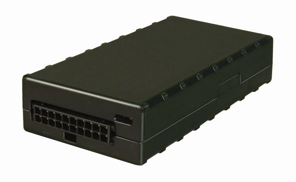
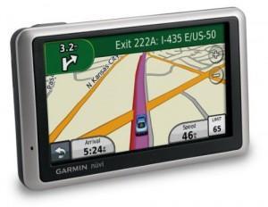
1 Click Your Device For Installation Instructions MTG-uL MTG-L MTG LMU2610 Barcode Scanner Garmin
2 StreetEagle Vehicle Unit Installation MTG-uL This installation guide will provide the guidelines for installing the StreetEagle Vehicle Tracking Unit (VTU). Insight USA will not warranty the reliability of the VTU, and will not provide compensation to the installer for service calls to the customer if the guidelines are not followed exactly. If you require any further assistance during the installation process please call Insight USA at (301) x208. Insight USA Provided Equipment StreetEagle VTU Wiring harness Dual-mode GPS / GPRS Mounting screws Tamper Evident Sealant Installation instructions ATM and Mini ATM Pigtail Fuses Insulated Butt Connectors Ring Terminal Other Equipment that may be needed Multi-meter Crimpers and the appropriate connectors Fuse taps Electric Drill (cordless) with ¼ socket, 5 / 16 socket, Phillips and flat screwdriver bit attachments, and 7 / 8 hole saw (for through hole antennas) Cable ties or self-adhesive tie mounts Alcohol wipes (for window mounts antennas) Installation Procedures 1. Write down your vehicles name or number. 2. Write down the serial number of the Tracking Unit that went in the above vehicle. 3. Find a suitable location and mount the VTU-- The vehicle unit must be mounted in the vehicle so that it is isolated from the elements. The trunk or cab of the vehicle is usually the most convenient. The unit must be mounted horizontally on the floor of the vehicle with the mounting screws. If this is impossible, a vertical mount may be used provided it is secured to a metal surface with at least 3 screws. Ideal mounting locations include, but are not limited to: on the floor behind/under the passenger seat, under the dash, bolted to the floor board, in the trunk mounted forward near the back of the passenger seats, etc.

3 4. Connect the Power and Discrete Cable--Use the wiring harness provided with your installation kit. DO NOT PLUG THE POWER CABLE INTO THE VTU AT THIS TIME!! Connect the wires according to the following table: Black White Red I/O 1 Green I/O 2 Blue Ground Ignition 12v is supplied only when ignition is on Battery 12v is supplied constantly, regardless of ignition state Ground when signal Active* Ground when signal Active* *Relay may be required when trying to implement an active low signal. See: Diagram for wiring a PTO Circuit 1. PWR/GPS- Always on. Resets with ignition. 2. USR2- turns on once GPS signal is acquired. 3. USR1- turns solid once cell signal is acquired Verify the Power and Discrete Connections-- Once all of the connections have been made, check power at the plug with a voltmeter. Make certain that the ignition signal is ONLY on when the vehicle is on, and that battery power is ALWAYS on regardless of the state of ignition.
4 6. Mount the Dual-Mode Antenna-- The GPS antenna must be mounted on the windshield of the vehicle so that it has an unobstructed view of the sky. Mount the antenna with the word UP facing toward the sky. Mounting surfaces of the glass MUST be cleaned with alcohol wipes prior to mounting the cellular antenna. Route the cable where it cannot be pinched, kinked or cut. The cellular antenna attaches to the VTU via the purple connector on the back of the VTU. The GPS antenna attaches to the VTU via the blue connector on the back of the VTU. ***Without a good view of the sky the antenna may cause the unit to report sporadically*** Suggested locations and orientation: glass mounted antennas should be placed high on the glass avoiding the defrosting elements, and the whip shall not touch any surrounding metal. 7. Connect the power cable to the VTU-- with the ignition off, and antennas connected, attach the power cable to the VTU. The retaining clip will snap into place when the connector is properly seated. 8. Turn on the ignition and call Insight USA-- call Insight USA at ext.208 to verify correct installation and functionality prior to proceeding to the next vehicle. Note: When the VTU is installed, it can take up to 20 minutes for the GPS to acquire its position after initial power-up. Subsequent position acquisition will be less than 30 seconds of the vehicle start-up. 9. Update the vehicle name in the Street Eagle Tracker control menu 10. Apply tamper evident sealant-- tamper evident sealant should be applied so that it attached to the cable and to the box. It should be used on the top of the power cable, and also on the GPS antenna cable and the GPRS antenna cable.
5 Diagram for wiring a PTO Circuit BOSCH (Standard automotive horn relay)
6 StreetEagle Vehicle Unit Installation MT-GL This installation guide will provide the guidelines for installing the StreetEagle Vehicle Tracking Unit (VTU). Insight USA will not warranty the reliability of the VTU, and will not provide compensation to the installer for service calls to the customer if the guidelines are not followed exactly. If you require any further assistance during the installation process please call Insight USA at (301) x208. Insight USA Provided Equipment StreetEagle VTU Wiring harness Dual-mode GPS / GPRS Mounting screws Tamper Evident Sealant Installation instructions ATM and Mini ATM Pigtail Fuses Insulated Butt Connectors Ring Terminal Other Equipment that may be needed Multi-meter Crimpers and the appropriate connectors Fuse taps Electric Drill (cordless) with ¼ socket, 5 / 16 socket, Phillips and flat screwdriver bit attachments, and 7 / 8 hole saw (for through hole antennas) Cable ties or self-adhesive tie mounts Alcohol wipes (for window mounts antennas) Installation Procedures 1. Write down your vehicles name or number. 2. Write down the serial number of the Tracking Unit that went in the above vehicle. 3. Find a suitable location and mount the VTU-- The vehicle unit must be mounted in the vehicle so that it is isolated from the elements. The trunk or cab of the vehicle is usually the most convenient. The unit must be mounted horizontally on the floor of the vehicle with the mounting screws. If this is impossible, a vertical mount may be used provided it is secured to a metal surface with at least 3 screws. Ideal mounting locations include, but are not limited to: on the floor behind/under the passenger seat, under the dash, bolted to the floor board, in the trunk mounted forward near the back of the passenger seats, etc.
7 4. Connect the Power and Discrete Cable--Use the wiring harness provided with your installation kit. DO NOT PLUG THE POWER CABLE INTO THE VTU AT THIS TIME!! Connect the wires according to the following table: Black White Red I/O 1 I/O 2 Ground Ignition 12v is supplied only when ignition is on Battery 12v is supplied constantly, regardless of ignition state Ground when signal Active* Ground when signal Active* *Relay may be required when trying to implement an active low signal. See: Diagram for wiring a PTO Circuit 4. PWR/GPS- always on (resets with ignition). 5. USR2- turns on once GPS signal is acquired. 6. USR1- turns solid once cell signal is acquired Verify the Power and Discrete Connections-- Once all of the connections have been made, check power at the plug with a voltmeter. Make certain that the ignition signal is ONLY on when the vehicle is on, and that battery power is ALWAYS on regardless of the state of ignition.
8 6. Mount the Dual-Mode Antenna-- The GPS antenna must be mounted on the windshield of the vehicle so that it has an unobstructed view of the sky. Mount the antenna with the word UP facing toward the sky. Mounting surfaces of the glass MUST be cleaned with alcohol wipes prior to mounting the cellular antenna. Route the cable where it cannot be pinched, kinked or cut. The cellular antenna attaches to the VTU via the Silver TNC connector on the back of the VTU. The GPS antenna attaches to the VTU via the Gold SMA connector on the back of the VTU. ***Without a good view of the sky the antenna may cause the unit to report sporadically*** Suggested locations and orientation: glass mounted antennas should be placed high on the glass avoiding the defrosting elements, and the whip shall not touch any surrounding metal. 7. Connect the power cable to the VTU-- with the ignition off, and antennas connected, attach the power cable to the VTU. The retaining clip will snap into place when the connector is properly seated. 8. Turn on the ignition and call Insight USA-- call Insight USA at ext.208 to verify correct installation and functionality prior to proceeding to the next vehicle. Note: When the VTU is installed, it can take up to 20 minutes for the GPS to acquire its position after initial power-up. Subsequent position acquisition will be less than 30 seconds of the vehicle start-up. 9. Update the vehicle name in the Street Eagle Tracker control menu 10. Apply tamper evident sealant-- tamper evident sealant should be applied so that it attached to the cable and to the box. It should be used on the top of the power cable, and also on the GPS antenna cable and the GPRS antenna cable.
9 Diagram for wiring a PTO Circuit BOSCH (Standard automotive horn relay)
10 StreetEagle Vehicle Tracking Unit Installation MT-G This installation guide will provide the guidelines for installing the StreetEagle Vehicle Tracking Unit (VTU). Insight USA will not warranty the reliability of the VTU, and will not provide compensation to the installer for service calls to the customer if these guidelines are not followed exactly. If you require any further assistance during the installation process please call Insight USA at (301) x208. Insight USA Provided Equipment StreetEagle VTU Wiring harness Dual-mode GPS / GPRS antenna Mounting screws Tamper Evident Sealant Installation instructions ATM and Mini ATM Pigtail Fuses Insulated Butt Connectors Ring Terminal Other Equipment that may be needed Multi-meter Crimpers and the appropriate connectors Fuse taps Electric Drill (cordless) with ¼ socket, 5/16 socket, Phillips and flat screwdriver bit attachments, and 7/8 hole saw (for dual mode antennas) Cable ties or self-adhesive tie mounts Alcohol wipes (for window mount antennas) Installation Procedures 1. Write down your vehicles name or number. 2. Write down the serial number of the Tracking Unit that went in the above vehicle. 3. Find a suitable location and mount the VTU -- The vehicle unit must be mounted in the vehicle so that it is isolated from the elements. The trunk or cab of the vehicle is usually the most convenient. The unit must be mounted horizontally on the floor of the vehicle with mounting screws. If this is impossible, a vertical mount may be used provided it is secured to a metal surface with at least 3 screws. Ideal mounting locations include, but are not limited to: on the floor behind/under the passenger seat, under the dash bolted to the floor board, in the trunk mounted forward near the back of the passenger seats, etc. 4. Connect the Power and Discrete Cable -- Use the wiring harness provided with your installation kit. DO NOT PLUG THE POWER CABLE INTO THE VTU AT THIS TIME!! Connect the wires according to the following table:
11 Black White Red Ground Ignition > 12v is supplied only when ignition is on Battery > 12v is supplied constantly, regardless of ignition state 5. Verify the Power and Discrete Connections -- Once all of the connections have been made, check power at the plug with a voltmeter. Make certain that the ignition signal is ONLY on when the vehicle is on, and that battery power is ALWAYS on regardless of the state of the ignition. 6. Mount the GPS (or Dual-Mode)Antenna -- The GPS antenna must be mounted on the windshield of the vehicle so that it has an unobstructed view of the sky. Mounting surfaces of the glass MUST be cleaned with alcohol wipes prior to mounting the cellular antenna. Route the cable where it cannot be pinched, kinked or cut. The cellular antenna attaches to the VTU via the TNC connector on the back of the VTU. Suggested locations and orientation: glass mounted antennas should be placed high on the glass avoiding the defrosting elements, and the whip shall not touch any surrounding metal. 7. Connect the power cable to the VTU with the ignition off, and antennas connected, attach the power cable to the VTU. The retaining clip will snap into place when the connector is properly seated. 8. Turn on the ignition and call Insight USA call Insight USA at ext.208 to verify correct installation and functionality prior to proceeding to the next vehicle. Note: When the VTU is installed, it can take up to 20 minutes for the GPS to acquire its position after initial power-up. Subsequent position acquisition will be less than 30 seconds of vehicle start-up. 9. Update the vehicle name in the Street Eagle Tracker control menu 10. Apply tamper evident sealant tamper evident sealant should be applied so that it attaches to the cable and to the box. It should be used on the top of the power cable, and also on the GPS antenna cable and the GPRS antenna cable.
12 Barcode Scanner Install Guide This installation guide will provide the guidelines for installing a Barcode Scanner unit connection to the StreetEagle device. Insight USA will not warranty the reliability of the VTU, and will not provide compensation to the installer for service calls to the customer if the guidelines are not followed exactly. If you require any further assistance during the installation process please call Insight USA at (301) x208. Insight USA Provided Equipment StreetEagle device Wiring harness Scanner and Base Installation instructions Optional Equipment if ordered: o ATM and Mini ATM Pigtail Fuses o Insulated Butt Connectors o Ring Terminal Other Equipment that may be needed Multi-meter Crimpers and the appropriate connectors Fuse taps Electric Drill (cordless) with bit attachments Cable ties or self-adhesive tie mounts Installation Procedures 1. Find a suitable location to mount the Barcode scanner-- The barcode scanner must be mounted where the driver can access the barcode scanner easily. Make sure the scanner is be mounted securely and will not fall. 2. Connect the serial cable-- Plug the serial cable from the StreetEagle vehicle-tracking unit into the data port on the barcode scanner cable. 3. Connect the power cable-- The barcode scanner must receive switch power in order for the barcode scanner to function properly. The red wire must be wire to switched 12-volt power source. The black wire must be attached to chassis ground. The barcode scanner will only transmit data when vehicle is turned on. 4. Scanner Data Setup--The scanner needs to be setup by scanning the Barcode Scanner Setup for >>>(data)<<< provided on the next page.
 6. Send All that Remains 7. Send ASCII key < (Scan 3 times) 8. Save Rule 9.")
13 Barcode Scanner Setup for >>>(data)<<< (It is very important that the barcodes are scanned in numerical order starting with number 1.) 1. Set factory default 2. Set Host Type 3. Erase rules 4. Begin New Rule 5. Send ASCII key > (Scan 3 times) 6. Send All that Remains 7. Send ASCII key < (Scan 3 times) 8. Save Rule 9. Now scan the base that is installed in the vehicle
14 Garmin Installation Guide This installation guide will provide the guidelines for installing a Garmin unit with connection to the StreetEagle device. Insight USA will not warranty the reliability of the VTU, and will not provide compensation to the installer for service calls to the customer if the guidelines are not followed exactly. If you require any further assistance during the installation process please call Insight USA at (301) x208. Insight USA Provided Equipment StreetEagle device Wiring harness Installation instructions Optional Equipment if ordered: o Cigarette lighter socket P/N: 12VDCSOCKET o ATM and Mini ATM Pigtail Fuses o Insulated Butt Connectors o Ring Terminal Other Equipment that may be needed Multi-meter Crimpers and the appropriate connectors Fuse taps Electric Drill (cordless) with bit attachments Cable ties or self-adhesive tie mounts Installation Procedures 1. Upgrade Firmware-- Visit click Support> Software Updates> Unit Software, then follow the instructions to update the firmware on the Garmin. (if you purchased the Garmin directly from Insight USA this step has been completed for you) Occasionally updating the Garmin unit maybe needed to take advantage of new functionality. 2. Find a suitable location to mount the Garmin-- The Garmin unit must be mounted where driver will not be distracted. The unit must also be able to receive a valid GPS signal. Be sure the unit will be mounted securely and will not fall. ***Check local and State Laws on mounting the Garmin unit to the windshield. 3. Connect the serial cable-- Plug the serial cable from the StreetEagle device into the data port on the Garmin. For Garmins with docking stations, plug the data cable into the dock then dock the Garmin unit. 4. Connect the power cable-- The Garmin unit must receive constant power. In order for the Garmin to function properly, the Garmin must also be powered on at all times. If the vehicle does not supply constant power to the cigarette lighter, P/N: 12VDCSOCKET must be ordered and connected Wire Cigarette lighter- (if necessary) Connect the Positive (red) wire to a constant +12volts source. Connect the Negative (black) wire to a chassis ground. Run the socket to a suitable mounting location and connect the Garmin power cable to it. Every time the Garmin is first turned on the No Communication symbol will appear until the unit receives a message or route.

15 Garmin Trouble Shooting Guide If the Garmin is not receiving Routes or Messages check the following: Update Garmin software. This can be done via the WebUpdater utility provide on Garmin s website (Please visit and select WebUpdater for more details) The Garmin must be plugged into constant power via either hardwired or through the cigarette lighter plug (cannot run off battery alone) Communication cable must be plugged into data port on the side of the Garmin. Every time the Garmin is first turns on the No Communication symbol will appear until the unit receives a message or route. If this symbol does not disappear please verify the above first and if not resolved contact Insight Technical Support.
 Standard Cable Legacy Garmins No longer in production (P/N 010-10813-00) Specialty cable Legacy Garmins No")

16 Compatible Garmins Garmin Unit Number FMI 10.2 cable (P/N ) Standard Cable Legacy Garmins No longer in production (P/N ) Specialty cable Legacy Garmins No longer in production (P/N ) DEZL Series Nuvi 24xx Nuvi 23xx Nuvi 14xx Nuvi 13xx Nuvi 12xx Nuvi 465T Nuvi 2x5 Nuvi 350 Nuvi 360 Nuvi 550 Nuvi 600 Nuvi 650 Nuvi 660 Nuvi 680 Nuvi 750 Nuvi 755T Nuvi 760 Nuvi 880 Nuvi 5000 Street Pilot 2720 Street Pilot 2820 Street Pilot 7200 Street Pilot 7500 Street Pilot c340 Street Pilot c530 Street Pilot c550 Street Pilot c580
17 StreetEagle Vehicle Unit Installation LMU2600 Insight USA Provided Equipment StreetEagle VTU Wiring harness Mounting screws Tamper Evident Sealant Installation instructions Insulated Butt Connectors Ring Terminal Serial accessory harness (OPTIONAL) Dual-mode GPS /GPRS antenna (OPTIONAL) ATM and Mini ATM Pigtail Fuses Required Tools and Supplies Fuse taps Precautions Crimpers and the appropriate connectors Drill with screwdriver and bit attachments Cable ties or self-adhesive tie mounts 12v DC Power only. The Vehicle Tracking Unit (VTU) is designed for negative ground 12V DC systems only. Do not use the VTU with any other power systems. Do not disassemble or modify the VTU. This could cause electric shock, personal injury or fire. Do not connect power from a different system to the VTU. When in doubt of a safe installation, please contact your local installer. Do not install VTU in locations that interfere with airbag operation. This could cause a risk of accidents and injury. Use only specified fuse. When replacing the fuse, please ensure the amp rating is the same as the previous fuse. Cautions Do not let wires get punctured by screws or caught in moving parts. Turn car ignition off before making connections. Connect the Red and White power input leads after all other connections have been made. Use a common ground point for all ground wires. Tape and insulate any loose unconnected wires. Note on power wire (Red) When connecting VTU in combination with other electric devices, be sure the vehicles circuit amp rating is higher than the sum of each component s fuse.
18 This installation guide provides detailed instructions for installing the StreetEagle Vehicle Tracking Unit (VTU). These instructions must be followed precisely to insure correct operation of the GPS Tracking unit and to ensure warranty coverage of the equipment. Please call StreetEagle Support at (301) x208 if you require assistance. Installation Procedures 1. Write down-- Using the vehicle information card, record the name or vehicle identification number for later reference. 2. Find a suitable location and mount the VTU-- The VTU must be mounted inside the vehicle in a weatherproof location. The trunk or dash of the vehicle is usually the most convenient. Ensure the unit is securely affixed and will not come loose from the mounting location due to severe vehicle motion. When Using Internal Antenna Models: The VTU should be mounted in the dash, unobstructed by metal and with a direct line of sight to the sky. Please ensure that the VTU s GPS Side is facing the sky. This is marked by a sticker on the VTU, showing GPS THIS SIDE UP. Examples OK(Yellow) and Poor(Red) internal antenna placements 3. Mount the Dual-Mode Antenna (if required)-- The antenna should be mounted in the dash, unobstructed by metal and with a direct line of sight to the sky. Mounting surfaces MUST be cleaned with alcohol wipes prior to mounting the antenna. The antenna must be mounted with the GPS (T/R or UP) side facing the sky. This is the side of the antenna covered with tape. Route the cable where it cannot be pinched, kinked or cut. The cellular antenna connects to the tracking unit via SMA (larger) screw on connector. The GPS antenna connects to the tracking unit via SMB (smaller) screw on connector. ***Without a good view of the sky the antenna may cause the unit to report sporadically*** Examples of Good (Green), OK(Yellow) and Poor(Red) Dual Mode antenna placements
19 4. Connect the Power and Discrete Cable-- Use the wiring harness provided with your installation kit. DO NOT PLUG THE POWER CABLE INTO THE VTU AT THIS TIME!! Connect the wires according to the following table: Primary connections Highlighted in RED Input Connections Highlighted in Orange Output Connections Highlighted in Gray Pin Description Lead Color Connection 1 AU 1 Black N/A 2 Ignition Disable Green Ground output to Ignition disable harness 3 Input 1* Blue Chassis Ground when discrete device is active 4 AU 1 Blue N/A 5 Not Used Pink N/A 6 Input 3* Violet Chassis Ground when discrete device is active 7 Not Used Grey N/A 8 Ignition White 12v when Ignition is on 9 AU 1 /AU 2 Orange N/A 10 Not Used Brown N/A 11 Door Unlock Yellow Ground pulse to negative side of door unlock switch 12 Input 2* Orange Chassis Ground when discrete device is active 13 AU 1 Green N/A 14 Primary Power Input Red 12v constant power 15 Primary Ground Black Chassis ground 16 Not Used Black N/A 17 Not Used White/Blue Stripe N/A 18 AU 2 White/Orange Stripe N/A 19 AU 2 Black N/A 20 AU 2 White/Yellow Stripe N/A *Relay may be required when trying to implement an active low signal. See: Diagram for wiring a PTO Circuit Serial Devices- To connect a Garmin or other serial device, plug an optional accessory cable into the main LMU harness 5-pin Auxiliary port Pig-Tails. Garmin devices must always use the AU 2 port from the LMU wiring harness. All other serial devices (Barcode Scanners, Passenger Counters, etc.) will use AU 1.
20 - 5. Verify the Power and Discrete Connections-- Once all of the connections have been made, check power at the plug with a voltmeter. Make certain that the ignition signal is ONLY on when the vehicle is on, and that battery power is ALWAYS on regardless of the state of ignition. 6. Connect the power cable to the VTU-- With the ignition off, and antennas connected, attach the power cable to the VTU. The retaining clip will snap into place when the connector is properly seated. 7. Turn on the ignition and call Insight USA-- Call Insight USA at ext.208 to verify correct installation and functionality prior to proceeding to the next vehicle. Note: When the VTU is installed, it can take up to 20 minutes for the GPS to acquire its position after initial power-up. Subsequent position acquisition will be less than 30 seconds of the vehicle start-up. 8. Update the vehicle name-- Using the Vehicle information card for reference, enter the new vehicle name in the Street Eagle Tracker control menu 9. Apply tamper evident sealant-- Tamper evident sealant should be applied so that it attached to the cable and to the box. It should be used on the top of the power cable, and also on the GPS antenna cable and the GPRS antenna cable.
21 Diagram for wiring a PTO Circuit BOSCH (Standard automotive horn relay)
 Definitions Condition LED 1 Modem Off Off Comm On - Searching Slow Blinking Network Available Fast Blinking")
22 LMU Tracking Unit Troubleshooting Guide The LMU-2600 is equipped with two Status LEDs, one for GPS and one for COMM (wireless network status). The LEDs use the following blink patterns to indicate service: LED #1 (Comm LED - Orange) Definitions Condition LED 1 Modem Off Off Comm On - Searching Slow Blinking Network Available Fast Blinking Registered but no Inbound Acknowledgement Alternates from Solid to Fast Blink every 1s Registered and Received Solid Inbound Acknowledgement LED #2 (GPS LED - Yellow) Definitions Condition LED 1 GPS Off Off GPS On Slow Blinking GPS Time Sync Fast Blinking GPS Fix Solid No LED lit Problem Both LED s always lit (should reset with ignition) Comm LED is slow blinking, no cell signal GPS LED is not lit, no GPS signal Time updates/changes, location does not Solution The unit is not getting constant power/or ground The white wire is connected to constant power, the white wire should be moved to a switched power source Check for proper installation of the unit (or antenna) verify that the SIM card is seated properly verify that the data account is active Verify proper installation of the unit (or antenna), verify that GPS side is up and has a clear view of the sky GPS antenna is unplugged or view of sky is obstructed
Nero 6600H/6601H. Installation Guide. Commercial Vehicle Productivity and Security. Antenna Configuration
 Commercial Vehicle Productivity and Security The 6600H/6601H is a versatile and economical GPS tracking beacon designed for fleet management needs in all commercial vehicles. The H designation in the model
xtablet T7000 Vehicle Mount Kit
 xtablet T7000 Vehicle Mount Kit Installation & Users Guide Last Updated: January 19, 2012 Find the latest updates in the Support section in the MobileDemand website at: www.ruggedtabletpc.com. Questions?
Networkfleet 3500 Product Line Installation Guide
 Networkfleet 3500 Product Line Installation Guide Light/Medium Duty (L3500) Heavy Duty (H3500) Universal (U3500) www.networkcar.com/fleet Customer Care: (866) 227-7323 customercare@networkcar.com Table
Installation Instructions TRACKNET TN-4003/4004
 Installation Instructions TRACKNET TN-4003/4004 TABLE OF CONTENTS TABLE OF CONTENTS Introduction... 2 Installation Caution and Warnings... 3 Control Module and Components... 3-4 Mounting Location...4-5
Wired Real Time GPS Installation Instructions
 Wired Real Time GPS Installation Instructions This page intentionally left blank. TABLE OF CONTENTS 1. Introduction 2 2. Selecting the Mounting Location for the Device. 3 3. Mounting the Device 5 4. Optional
Onboard. Onboard RTU270 Installation Manual
 Onboard Onboard RTU270 Installation Manual Contents Parts Checklist 3 Pre-installation considerations 4 Installation 5 Status LEDs 7 Completing Installation 8 2 Onboard RTU270 Installation Parts Check
Installation Instructions for VTU
 Installation Instructions for VTU 1 Introduction This installation manual covers the installation of the Vehicle Tracking Unit (VTU). This manual is for the professional and novice installer and should
IVTM Installation Manual
 Integrated Vehicle Tire Pressure Monitoring IVTM Installation Manual 2nd edition Copyright WABCO 2006 Vehicle Control Systems An American Standard Company The right of amendment is reserved Version 002/06.06(us)
Covers All 430, 440, 441 and CJ Series Advanced Security Systems.
 INSTALL GUIDE Covers All 430, 440, 441 and CJ Series Advanced Security Systems www.ultrastarters.com Technical Support: 866-698-5872 ext 0 support@ultrastarters.com FCC/ID Notice This device complies with
GPS-D4550. Installation And Testing Guide VEHICLE TRACKING & RECOVERY SYSTEM. Model: Quick Reference Install Guide
 Model: GPS-D550 VEHICLE TRACKING & RECOVERY SYSTEM Installation And Testing Guide Quick Reference Install Guide 1 2 3 5 6 7 8 Write the VIN (Vehicle Identification Number) on the mirror hanger/activation
AWARE TM VEHICLE INTELLIGENCE INSTALLATION MANUAL
 AWARE TM VEHICLE INTELLIGENCE INSTALLATION MANUAL FOR INTERNATIONAL TRUCKS CXT, RXT, MXT, 3200, 4100, 4200, 4300, 4400, 7300, 7400, 7500, 7600, 7700, 8500 and 8600 For Models Built After 2007 MODULES ARE
Vehicle Security System
 Installation Instructions Vehicle Security System PROFESSIONAL INSTALLATION STRONGLY RECOMMENDED Installation Precautions: Roll down window to avoid locking keys in vehicle during installation Avoid mounting
ROADRELAY 5 Installation Guide
 ROADRELAY 5 Installation Guide ROADRELAY 5 Installation Guide Bulletin No. 4971214 Revision A Copyright 2011, Cummins Inc. All rights reserved. Cummins Inc. shall not be liable for technical or editorial
REC-11+ REMOTE RECEIVER UNIT
 Resetting The Programmable Features The installer may quickly and easily return all 17 programmable features back to the factory settings. Changing individual features were explained in detail in the previous
Vehicle Security System
 Installation Instructions Vehicle Security System PROFESSIONAL INSTALLATION STRONGLY RECOMMENDED Installation Precautions: Roll down window to avoid locking keys in vehicle during installation Avoid mounting
INSTALLATION MANUAL SPECTRUM BRAKE CONTROL
 INSTALLATION MANUAL 51170 SPECTRUM BRAKE CONTROL TABLE OF CONTENTS Controls & Components Tools List Before You Begin Wiring Wiring Diagram Mounting the LED Display Rotary Knob Wiring the Plug Connector
CP 634 DELUXE 4-CHANNEL KEYLESS ENTRY SYSTEM
 CP 634 DELUXE 4-CHANNEL KEYLESS ENTRY SYSTEM Installation And Operation Manual MEGATRONIX VAN NUYS, CA U.S.A. CP634 1 REMOTE CONTROL CONVENIENT SYSTEM INSTALLATION & OPERATION INSTRUCTIONS INTRODUCTION
SAFETY-- SECURITY-- SIMPLICITY! TM
 T3 Vehicle Security Tracker Installation Guide SAFETY-- SECURITY-- SIMPLICITY! TM 911Tracker.com T3 Vehicle Security Tracker Installation Guide COPYRIGHTS 2017 911Tracker All rights reserved. 911Tracker
INSTALLATION MANUAL. Middle. Def tank. Standard. Middle. Standard. Def tank WARNING. Level of Difficulty CAUTION. Parts List.
 INSTALLATION MANUAL 3025101 Level of Difficulty Moderate This is the second first of two of two manuals required to complete this installation. The first second manual manual is is included with with your
INSTALLATION INSTRUCTIONS
 INSTALLATION INSTRUCTIONS Accessory REMOTE CONTROL Application 2008 CR-V Publications No. AII 35843-38422 Issue Date DEC 2007 PARTS LIST Caution label Remote Engine Starter Kit P/N 08E91-E22-100B Transmitter
jegs.com
 Contents Wiring Harness w/ Fuse Panel Installation Instructions Turn Signal Plug w/ Terminals 2 Headlight Plugs 3/4 Grommet 10 ¼ Terminals 4 Ring Terminals 10 Wire Ties Fusible Link 2 Screws & Nuts 2 Plastic
INSTALLATION MANUAL. Cab-Mate Connect (LMU4233) Document ID: IM-CMC Last Updated: December 18, PedigreeTechnologies.com Support: (701)
 Document ID: IM-CMC Last Updated: December 18, PedigreeTechnologies.com Support: (701)") INSTALLATION MANUAL Cab-Mate Connect (LMU4233) Document ID: IM-CMC Last Updated: December 18, 2018 Pedigree Technologies recommends using a professional installer for optimal results. Please let your Pedigree
INSTALLATION MANUAL Cab-Mate Connect (LMU4233) Document ID: IM-CMC Last Updated: December 18, 2018 Pedigree Technologies recommends using a professional installer for optimal results. Please let your Pedigree
I. Introduction - basic information 3 II. Installation into a vehicle 3. III. Attachments 9
 ampire FLEET200 Contents I. Introduction - basic information 3 II. Installation into a vehicle 3 1. Placement of the unit 3 2. Connecting the wiring harness 4 2.1 Input - IGNITION 6 2.2 Input BUSINESS
PRELIMINARY INSTALLATION INSTRUCTIONS. Remote Engine Starter Attachment Kit P/N 08E92-SNA-100B
 INSTALLATION INSTRUCTIONS Accessory Application Publications No. REMOTE ENGINE STARTER SYSTEM 2008 CIVIC 2-DOOR AII 38215 Issue Date OCT 2007 PARTS LIST Remote Engine Starter Unit Kit P/N 08E91-E22-100B
I. SIM card preparation 3 II. Installation into a vehicle 3. III. Most common issues and their solutions 9 III. Attachments 10
 Contents I. SIM card preparation 3 II. Installation into a vehicle 3 1. Placement of the unit 3 2. Connecting the wiring harness 4 2.1 Input - IGNITION 6 2.2 Input ALARM INPUT 6 2.3 Output (switching relay)
Installation Instructions for TM470 Interfacing with 1708 and 1939.
 Installation Instructions for TM470. Interfacing with 1708 and 1939. Date 8/20/2012 FCR draft 1.07 Table of Contents Overview... 1 Kit Components...1 Differences between the TM450 and the TM470... 2 Main
Vehicle Security System
 Installation Instructions Vehicle Security System PROFESSIONAL INSTALLATION STRONGLY RECOMMENDED Installation Precautions: Roll down window to avoid locking keys in vehicle during installation Avoid mounting
ITCEMS950 Idle Timer Controller - Engine Monitor Shutdown Isuzu NPR 6.0L Gasoline Engine
 Introduction An ISO 9001:2008 Registered Company ITCEMS950 Idle Timer Controller - Engine Monitor Shutdown 2014-2016 Isuzu NPR 6.0L Gasoline Engine Contact InterMotive for additional vehicle applications
INSTALLATION INSTRUCTIONS
 INSTALLATION INSTRUCTIONS Accessory REMOTE ENGINE STARTER SYSTEM Application 2010 CIVIC 4-DOOR Publications No. AII 42460 Issue Date AUG 2009 PARTS LIST Remote Engine Starter Unit Kit P/N 08E91-E22-100B
Keyless Upgrade Alarm
 Toyota Matrix 009 - Keyless Upgrade Alarm Part Number: 0006-940 Accessory Code: QS Kit Contents Item # Quantity Reqd Description Security Module Shock Sensor 3 LED Valet Switch 4 HP Switch Ext. 5 Window
CSI-300 Installation Instructions
 CSI-300 Installation Instructions Kit Contents Installation Precautions: Roll down window to avoid locking keys in vehicle during installation Avoid mounting components or routing wires near hot surfaces
OEM Lip Mount Camera with Harness and OnStar Mirror for GM Vehicles with 16-pin Mirror Connector (Kit part number )
") OEM Lip Mount Camera with Harness and OnStar Mirror for GM Vehicles with 16-pin Mirror Connector (Kit part number 9002-8722) Please read thoroughly before starting installation and check that kit contents
OEM Lip Mount Camera with Harness and OnStar Mirror for GM Vehicles with 16-pin Mirror Connector (Kit part number 9002-8722) Please read thoroughly before starting installation and check that kit contents
SERIES 700/700E FACTORY KEYLESS UPGRADE INSTALLATION MANUAL
 SERIES 700/700E FACTORY KEYLESS UPGRADE INSTALLATION MANUAL Items Supplied with the System: Installation Instructions: Main unit 1. Mounting the module: Plug In LED Mount the module in a suitable location
INSTALLATION GUIDE Car Show Dual DVD Headrest Replacement System
 INSTALLATION GUIDE Car Show Dual DVD Headrest Replacement System NOTICE OF INTENDED INSTALLATION AND USE CAR SHOW VIDEO PRODUCTS ARE NOT INTENDED FOR VIEWING BY THE DRIVER, AND ARE TO BE INSTALLED ONLY
AWARE VEHICLE INTELLIGENCE TM INSTALLATION MANUAL FOR STERLING MODELS
 AWARE VEHICLE INTELLIGENCE TM INSTALLATION MANUAL FOR STERLING MODELS 2001 ACTERRA AND NEWER MODULES ARE NOT ACTIVATED WHEN SHIPPED. PLEASE SEE THE ACTIVATION GUIDE. 1 March 6 th, 2008 TABLE OF CONTENTS
Idle Timer Controller - A-ITC520-A Ford E Series Ford F250 - F Ford F250 - F550 (*B-ITC520-A) F650/F750
 F650/F750") An ISO 9001:2008 Registered Company Idle Timer Controller - A-ITC520-A 2009-2018 Ford E Series 2008-2016 Ford F250 - F550 2017-2018 Ford F250 - F550 (*B-ITC520-A) 2016-2018 F650/F750 *Uses the Ford 24-Pin
An ISO 9001:2008 Registered Company Idle Timer Controller - A-ITC520-A 2009-2018 Ford E Series 2008-2016 Ford F250 - F550 2017-2018 Ford F250 - F550 (*B-ITC520-A) 2016-2018 F650/F750 *Uses the Ford 24-Pin
COMMANDO REMOTE CONTROL ENGINE STARTER. Limited Warranty Statement MADE IN THE U.S.A. IMPORTANT KEEP YOUR INVOICE WITH THIS WARRANTY STATEMENT!
 Limited Warranty Statement GNU COMMANDO LINE WARRANTY STATEMENT GNU warrants this product to be free from defects in material and workmanship for a period of one (1) year from the date of sale to the original
1. Check the contents of the installation kit
 DC3 Video Event Recorder Standard Installation Instructions Installation of the event recorder is not complicated, but care must be taken to ensure successful operation. Follow these instructions carefully
INSTALLATION INSTRUCTIONS
 INSTALLATION INSTRUCTIONS Accessory REMOTE CONTROL ENGINE STARTER Application 2010 CR-V Publications No. AII 42612-42916 Issue Date OCT 2009 PARTS LIST Remote Engine Starter Unit Kit P/N 08E91-E22-101B
INSTALLATION INSTRUCTIONS
 INSTALLATION INSTRUCTIONS Accessory REMOTE CONTROL Application 2011 ODYSSEY (EXCEPT LX) Publications No. AII 43923 Issue Date SEP 2010 PARTS LIST Remote Control Engine Starter Unit Kit P/N 08E91-E22-101A
INSTALLATION GUIDE AV7900 Dual Multimedia Headrest Replacement System
 INSTALLATION GUIDE AV7900 Dual Multimedia Headrest Replacement System NOTICE OF INTENDED INSTALLATION AND USE AV7900 VIDEO PRODUCTS ARE NOT INTENDED FOR VIEWING BY THE DRIVER, AND ARE TO BE INSTALLED ONLY
TOYOTA TACOMA LED DRL. Part Number: TTA-712
 Part Number: TTA-712 Kit Contents Item # Quantity Reqd. Description 1 2 DRL s bezels w/led DRL 2 1 Driver Box 3 1 Harness bag 4 1 User s card 5 1 Switch Hardware Bag Contents Item # Quantity Reqd. Description
LGT-312L E-Z-Go TXT Light Bar Bumper Kit Installation Instructions
 LGT-312L E-Z-Go TXT 2014+ Light Bar Bumper Kit Installation Instructions Caution: Please read through the instructions carefully. Before starting this project, remove the system s positive and negative
RA2 Installation Manual Rev. B
 Important Information Required Installation Tools Voltmeter Wire Strippers Electric Drill & Bits Phillips Screwdriver Convoluted Tubing * Solder Gun * Wire Crimpers Shrink Tube or Electrical Tape * Optional
Applicable to the Following Part Numbers. Notes and Maintenance. Torque Specifications. Metric SAE. Use above torque setting unless otherwise noted
 INSTALLATION MANUAL Level of Difficulty Moderate This is the second first of two of two manuals required to complete this installation. The first second manual manual is is included with with your mounting
Part Number: TTA-712. Hardware Bag Contents. General Applicability All models
 Date: 09.30.2013 TOYOTA TACOMA 2012-15 LED DRL Part Number: TTA-712 Kit Contents Item # Quantity Reqd. Description 1 2 DRL s bezels w/led DRL 2 1 Driver Box 3 1 Harness bag 4 1 User s card 5 1 Switch Hardware
Brake and Tail Light Kit Workman 1100/2100 and Twister Utility Vehicles
 Form No. 5-90 Brake and Tail Light Kit Workman 00/00 and Twister Utility Vehicles Part No. 0 6697 Installation Instructions Important Before installing this kit, you must have Wiring kit number 99 79 installed
INSTALLATION INSTRUCTIONS
 INSTALLATION INSTRUCTIONS Accessory REMOTE CONTROL Application 2012 ODYSSEY (EXCEPT LX) Publications No. AII 46745 Issue Date SEP 2011 PARTS LIST Remote Control Engine Starter Unit Kit P/N 08E91-E22-101A
INSTALLATION INSTRUCTIONS
 Rear Vision System Liftgate Emblem Camera Mirror Display 2009-2012 Ford Flex (Kit part number 1008-9527) Kit Contents: Mirror Liftgate Emblem Mount with Camera Interior (shorter) Harness Chassis (longer)
VAM-HD Basic Installation
 VAM-HD Basic Installation DISCLAIMER: INFORMATION IN THIS DOCUMENT IS SUBJECT TO CHANGE WITHOUT NOTICE. FULL DETAILS OF ALL INFORMATION AND DISCLAIMERS RELATING TO THIS DOCUMENT AND THE PRODUCT IT DESCRIBES
User Guide. Asset Guard PW INSTALLATION GUIDE. Table of Contents GETTING STARTED... 2 HARDWARE MOUNTING... 3 DEVICE CONNECTIONS...
 User Guide Asset Guard PW INSTALLATION GUIDE Table of Contents GETTING STARTED... 2 HARDWARE MOUNTING... 3 DEVICE CONNECTIONS... 4 1 GETTING STARTED Asset Guard PW Overview The Verizon Networkfleet Asset
Diablo 2 /AMX 68/AT-58 Installation Manual 3/31/99
 1 Table of Contents Required Installation Tools... 2 Important Information... 2 Wiring Diagram.... 3 14 Pin Con nec tor... 4 Starter Dis able Relay...4 Installation Procedures...5 Control Unit... 5 Antenna...
RAM Rail Mount Kit RAM 201UD 5 Arm RAM 2461U Base RAM 235U Base, Double U-Bolt
 Note: Indented items indicate parts included in an assembly listed above. Part Name/Description Part Number Quantity Direct Command Kit 4100514 1 Installation Instructions 2005690 1 CAN Y-Splice 4000137
GreenRoad Installation Document (GRID) Document Number: VWR10
 Document Number: VWR10") GreenRoad Installation Document (GRID) Document Number: VWR10 Chassis: Volvo B10BLE Version Created By Date Body: Wright Renown 1.0 JP 15/06/2011 Year: 1998/2000 Configuration: Single Deck Bus Adherence
GreenRoad Installation Document (GRID) Document Number: VWR10 Chassis: Volvo B10BLE Version Created By Date Body: Wright Renown 1.0 JP 15/06/2011 Year: 1998/2000 Configuration: Single Deck Bus Adherence
U L T I M A T E R A D A R / L A S E R D E F E N S E S Y S T E M
 S m a r t e r Q u i e t e r M o r e A c c u r a t e U L T I M A T E R A D A R / L A S E R D E F E N S E S Y S T E M Installation Manual PASSPORT 9500ci Comes Complete Front Radar Receiver Miniature weatherproof
INSTALLATION INSTRUCTIONS
 OEM Lip Mount Camera with Harness and OnStar Mirror for GM Vehicles with 10-pin Mirror Connector (Kit part number 9002-8723) Items Included in the Kit: Bubble bag containing: Camera with Mount Mirror Mirror
Manual - Inside Front Cover (Blank)
") FRONT COVER Manual - Inside Front Cover (Blank) Table of Contents Important Information... 2 Recommended Installation Tools... 2 Recommended Procecures... 2 Wiring Diagram... 3 14 Pin Connector...4 Installation
FRONT COVER Manual - Inside Front Cover (Blank) Table of Contents Important Information... 2 Recommended Installation Tools... 2 Recommended Procecures... 2 Wiring Diagram... 3 14 Pin Connector...4 Installation
EROAD Ehubo Installation Guide
 EROAD Ehubo Installation Guide 2 1 Congratulations on purchasing your EROAD Ehubo IMPORTANT: Do not install or use the Ehubo until you have read this Installation Guide thoroughly. EROAD recommends the
Idle Timer Controller - ITC515-A Ford Transit Contact InterMotive for additional vehicle applications
 An ISO 9001:2008 Registered Company Idle Timer Controller - ITC515-A 2015-2018 Ford Transit Contact InterMotive for additional vehicle applications Overview The ITC515-A system will shut off gas or diesel
Part Number: SFR-713. Hardware Bag Contents. General Applicability All models. Conflicts - Fog Lights. Date: SCION FRS LED DRL
 Date: 01.30.2014 SCION FRS 2013-2015 LED DRL Part Number: SFR-713 Kit Contents Item # Quantity Reqd. Description 1 2 DRL s bezels w/led DRL 2 1 Driver Box 3 1 Harness bag 4 1 User s card 5 1 Switch Hardware
INSTALLATION MANUAL. Model: PLUS For Technical Assistance, please call (800) , or visit
 , or visit") R Vehicle Security INSTALLATION MANUAL Model: PLUS-4700 This device complies with part 15 of the FCC rules. Operation is subject to the following two conditions: (1) This device may not cause harmful interference;
R Vehicle Security INSTALLATION MANUAL Model: PLUS-4700 This device complies with part 15 of the FCC rules. Operation is subject to the following two conditions: (1) This device may not cause harmful interference;
TOYOTA VENZA 2009 TRAILER WIRE HARNESS Procedure
 Part Number: PT791-0T099 Kit Contents Item # Quantity Reqd. Description 1 1 Trailer Wire Harness Module 2 1 4-Flat Harness 3 1 Battery Power Wire Harness 4 1 Mounting Bracket, 4-Flat 5 2 Screw #10-24 6
POWERED RUNNING BOARDS INSTALLATION MANUAL
 POWE RUNNING BOARDS INSTALLATION MANUAL Level of Difficulty Moderate Parts List 1 Driver / left running board* 1 Passenger / right running board* 4 Mounting bracket, standard 2 Mounting bracket, middle
CS-865RKE Series II REMOTE KEYLESS ENTRY SYSTEM
 INTRODUCTION: CS-865RKE Series II REMOTE KEYLESS ENTRY SYSTEM INSTALLATION & OPERATING INSTRUCTIONS CONGRATULATIONS on your choice of a Remote Keyless Entry System by Crimestopper Security Products Inc.
Overview of operation modes
 Overview of operation modes There are three main operation modes available. Any of the modes can be selected at any time. The three main modes are: manual, automatic and mappable modes 1 to 4. The MapDCCD
INSTALLATION MANUAL. Fendt VarioGuide Ready COM 3 Supported Models PN REV A
 INSTALLATION MANUAL Fendt VarioGuide Ready COM 3 Supported Models 922 924 927 930 933 936 PN 602-0264-02 REV A LEGAL DISCLAIMER Note: Read and follow ALL instructions in this manual carefully before installing
Part Number: TAV-713 TOYOTA AVALON LED DRL
 Part Number: TAV-713 Kit Contents Item # Quantity Reqd. Description 1 2 DRL s bezels w/led DRL 2 1 Driver Box 3 1 Harness bag 4 1 User s card 5 1 Cushion pad 6 1 Switch 7 2 Drill Jigs Hardware Bag Contents
INSTALLATION INSTRUCTIONS
 INSTALLATION INSTRUCTIONS Accessory Application Publications No. AII 31716 HONDA (For ipod ) FIT Issue Date MAR 2006 PARTS LIST Attachment Kit P/N 08A28-1H1-800 4 Cushion tapes Honda Music Link Kit P/N
TOYOTA TACOMA Part Number: TTA-BGB16-DRL TTA-BGP16-DRL
 TOYOTA TACOMA 2016-17 Date: 10.29.2016 Billet Grille w/led DRL Part Number: TTA-BGB16-DRL TTA-BGP16-DRL Kit Contents Item # Quantity Reqd. Description 1 2 LED DRL 2 1 Driver Box 3 1 Switch 4 1 User Card
CA-110 Installation Instructions
 CA-110 Installation Instructions PROFESSIONAL INSTALLATION STRONGLY RECOMMENDED Installation Precautions: Roll down window to avoid locking keys in vehicle during installation Avoid mounting components
Security and Keyless Entry Installation Guide ca 1051
 PROFESSIONAL SERIES Security and Keyless Entry Installation Guide ca 1051 ca1051 rev B. 2011 Audiovox Electronics Corporation. All rights reserved. 1 Table of Contents Before You Begin... 3 Wire Connection
MEGA WAY LCD 4-CHANNEL CAR ALARM SECURITY SYSTEM. Installation Manual MEGATRONIX CALIFORNIA, USA MEGA 2500 INSTALL 1
 MEGA 2500 2-WAY LCD 4-CHANNEL CAR ALARM SECURITY SYSTEM Installation Manual MEGATRONI CALIFORNIA, USA MEGA 2500 INSTALL 1 MEGA 2500 INSTALL 2 INSTALLATION DIAGRAM H8: 10 Pin White Mini Connector H8 10
SCION FRS FOG LIGHTS. Part Number: SFR-313
 Part Number: SFR-313 Kit Contents Item # Quantity Reqd. Description 1 2 Light Housings 2 2 Fog Light bezels 3 1 Harness bag 4 1 User s card 5 1 Switch 6 1 Fuse jumper Hardware Bag Contents Item # Quantity
CAUTION. Even Brakes with a black cable need second vehicle kit Even Brakes with a blue cable need second vehicle kit 98450
 cable not included cable not included Even Brakes with a blue cable need second vehicle kit 98450 Even Brakes with a black cable need second vehicle kit 98400 Check the Even Brake serial number before
AviStart 3000 Installation Manual
 Table of Contents Important Information... 2 Recommended Installation Tools... 2 Recommended Procedures... 2 Main Wiring Diagram... 3 12 Pin Connector... 4 6 Pin Connector... 4 Installation Procedures...5
Conflicts: Vehicles with a sunroof
 Toyota 4Runner Non/MR 2010-10.2 Overhead Video Part Number: 00016-00110; Fit Kit -00110-15, Beige 00016-00120; Fit Kit -00120-15, Gray Accessory Code: ED6 Conflicts: Vehicles with a sunroof Kit Contents:
INSTALLATION MANUAL. Model: PLUS Vehicle Security
 R Vehicle Security INSTALLATION MANUAL Model: PLUS-5000 Copyright 1999 Magnadyne Corporation For Technical Assistance (800) 638-3600 For Fax on Demand Technical Assistance (800) 994-9977 (Must be a Registered
INSTALLATION INSTRUCTIONS
 INSTALLATION INSTRUCTIONS Accessory Application Publications No. P/N 08V31-SVA-100 2006 CIVIC 2-DOOR All 30890 Issue Date SEP 2005 PARTS LIST 11 Wire ties Right fog light Clip Left fog light 4 Stepped
INSTALLATION INSTRUCTIONS
 INSTALLATION INSTRUCTIONS Accessory REMOTE CONTROL Application Publications No. 2012 ACCORD AII 46522 2-DOOR Issue Date (A/T ONLY) AUG 2011 PARTS LIST Remote Engine Starter Unit Kit P/N 08E91-E22-101A
INSTALLATION INSTRUCTIONS
 INSTALLATION INSTRUCTIONS Accessory REMOTE CONTROL Application 2012 CR-V Publications No. AII 12085 Issue Date DEC 2011 PARTS LIST Remote Control Engine Starter Unit Kit P/N 08E91-E22-101A Accessory User
CLASSIC UPDATE WIRING KIT
 by Randy Irwin 1955-57 CLASSIC UPDATE WIRING KIT Randy Irwin - Technical Writer Randy has been involved in the Chevy parts business for over 25 years. He is a wizard at creating, making and modifying custom
ANTI-LOCK BRAKE SYSTEM
 ANTI-LOCK BRAKE SYSTEM 1993 Mitsubishi Diamante 1993 BRAKES Mitsubishi - Anti-Lock Brake System Diamante DESCRIPTION The Anti-Lock BRAKE SYSTEM (ABS) is designed to prevent wheel lock-up during heavy braking.
2005 and 09 Mustang install instructions Sequential / Chase Unit Partial Plug-N-Play Kit Meter4it Eng. Updated: 3/28/09
 Updated: 3/28/09 Verify content of kit: 1- Unit with wiring harness 1- Red power wire with 15 amp fuse 1- Color instruction 2- Velcro for mounting 1-Driver taillight harness 1- Passenger taillight harness
CSI-400 Installation Instructions
 CSI-400 Installation Instructions Kit Contents Installation Precautions: Roll down window to avoid locking keys in vehicle during installation Avoid mounting components or routing wires near hot surfaces
Chevrolet Camaro 2010-up S-LC
 INSTALLATION INSTRUCTIONS FOR PART 99-10S-LC APPLICATIONS Chevrolet Camaro 2010-up 99-10S-LC KIT FEATURES DIN and DDIN head unit provision Painted silver to match factory dash AXXESS Interface included
INSTALLATION INSTRUCTIONS
 INSTALLATION INSTRUCTIONS Accessory Application Publications No. CIVIC AII 24171 S 2- AND 4-DOOR Issue Date (DX, HX) AUG 2002 NOTE: Fog Lights cannot be installed if the vehicle is equipped with an optional
INSTALLATION INSTRUCTIONS
 INSTALLATION INSTRUCTIONS Accessory REMOTE CONTROL Application 2014 TSX (L4) Publications No. BII 50198 Issue Date SEPT 2013 PARTS LIST Remote Engine Starter Unit Kit P/N 08E91-TK4-200A Fuse label Transmitter
Part Number: TAV-713. Kit Contents Item # Quantity Reqd. Description 1 2 DRL s bezels w/led DRL. Hardware Bag Contents.
 Date: 09.04.2013 TOYOTA AVALON 2013 - LED DRL Part Number: TAV-713 Kit Contents Item # Quantity Reqd. Description 1 2 DRL s bezels w/led DRL 2 1 Driver Box 3 1 Harness bag 4 1 User s card 5 1 Cushion pad
INSTALLATION MANUAL. Remote Mobile Security System. Model: PL30
 Remote Mobile Security System INSTALLATION MANUAL Model: PL30 Copyright 1998 Magnadyne Corporation For Technical Assistance (800) 638-3600 For Fax on Demand Technical Assistance (800) 994-9977 (Must be
INSTALLATION GUIDE Table of Contents
 CT-3100 Automatic transmission remote engine starter systems. What s included..2 INSTALLATION GUIDE Table of Contents Door lock toggle mode..... 4 Notice...2 Installation points to remember. 2 Features..2
TL UNIVERSAL WIRING GUIDELINE TRCM - J jan18jh
 UNIVERSAL WIRING GUIDELINE TRCM - J1939 31jan18jh 1 Control Kits TABLE OF CONTENTS 1.1. TIK10103 Universal Automatic Foot Control for Hydraulic Brakes 1.2. TIK10104 Universal Automatic Foot Control for
INSTALLATION INSTRUCTIONS
 INSTALLATION INSTRUCTIONS Accessory REMOTE CONTROL Application 2008 ACCORD 4-DOOR Publications No. AII 35365 Issue Date AUG 2007 PARTS LIST U Accessory User s Information Manual Remote Engine Starter Unit
INSTALLATION INSTRUCTIONS
 INSTALLATION INSTRUCTIONS Accessory REMOTE CONTROL Application Publications No. 2009 ACCORD AII 39977-40931 4-DOOR Issue Date (A/T ONLY) NOV 2008 PARTS LIST Remote Engine Starter Unit Kit P/N 08E91-E22-100A
C FORD F250 / F L POWERSTROKE DIESEL WITH AUTOMATIC TRANSMISSIONS ONLY
 EXHAUST BRAKES C40019 1999-2003 FORD F250 / F350 7.3L POWERSTROKE DIESEL WITH AUTOMATIC TRANSMISSIONS ONLY Getting Started Thank you and congratulations on your purchase of a Pacbrake exhaust retarder.
Do isolate the power supply from other high power systems such as Stereos and Alarms
 Thank you for purchasing a Smart Ride Air Management System, AIRBAGIT.COM s premier flagship product. This system will meet all of your custom and utility needs and will provide you years of trouble free
INSTALLATION MANUAL. Remote Mobile Security System. Model: PL50
 Remote Mobile Security System INSTALLATION MANUAL Model: PL50 Copyright 2000 Magnadyne Corporation For Technical Assistance (800) 638-3600 For Fax on Demand Technical Assistance (800) 994-9977 (Must be
Adjustable Light Kits E-Z-Go TXT All Models Installation Instructions
 Adjustable Light Kits E-Z-Go TXT All Models 1996-2013 Installation Instructions Caution: Please read through the instructions carefully. Before starting this project, remove the system s positive and negative
INSTALLATION INSTRUCTIONS
 INSTALLATION INSTRUCTIONS Accessory Application Publications No. P/N 08V31-SVA-110 2007 CIVIC 2-DOOR All33536-34848 Issue Date FEB 2007 PARTS LIST 11 Wire ties Right fog light Clip Left fog light 4 Stepped
LGT-306L / LB Club Car Precedent LED Light Bar Bumper Kit Installation Instructions
 LGT-306L / LB Club Car Precedent LED Light Bar Bumper Kit Installation Instructions Caution: Please read through the instructions carefully. Before starting this project, remove the system s positive and