A WARNING GIVES THE READER INFORMATION WHICH IF DISREGARDED COULD CAUSE INJURY OR DEATH
|
|
|
- Barbra Oliver
- 6 years ago
- Views:
Transcription
1 EUROTHERM DRIVES 590A SERIES THREE PHASE CONVERTORS PRODUCT MANUAL A WARNING GIVES THE READER INFORMATION WHICH IF DISREGARDED COULD CAUSE INJURY OR DEATH All rights strictly reserved. No part of this document may be stored in a retrieval system, or transmitted in any form or by any means to persons not employed by a Eurotherm group company without written permission from Eurotherm Drives Ltd. Although every effort has been taken to ensure the accuracy of this document it may be necessary, without notice, to make amendments or correct omissions. Eurotherm Drives cannot accept responsibility for damage, injury, or expenses resulting therefrom. HA Issue 10
2 WARRANTY Eurotherm Drives warrants the goods against defects in design, materials and workmanship for the period of 12 months from the date of delivery on the terms detailed in Eurotherm Drives Standard Conditions of Sale IA058393C. Eurotherm Drives reserves the right to change the content and product specification without notice. COPYRIGHT in this document is reserved to Eurotherm Drives Ltd. INTENDED USERS This manual is to be made available to all persons who are required to configure, install or service the equipment described herein or any other associated operation.
3 WARNINGS AND INSTRUCTIONS THESE WARNINGS AND INSTRUCTIONS ARE INCLUDED TO ENABLE THE USER TO OBTAIN THE MAXIMUM EFFECTIVITY AND TO ALERT THE USER TO SAFETY ISSUES NEVER WORK ON THE CONTROLLER, MOTOR, OR AUXILIARY EQUIPMENT WITHOUT FIRST ISOLATING ALL SUPPLIES TO THE SYSTEM. This is a product of the restricted sales distribution class according to iec In a domestic environment this product may cause radio interference in which case the user may be required to take adequate measures. This product is designated as professional Equipment as defined in EN Permission of the supply authority shall be obtained before connection to the low voltage supply. APPLICATION AREA: Industrial (non consumer) motor speed control utilising dc shunt machines. PRODUCT MANUAL: The product manual is to provide a description of how the product works and is not intended to describe how the apparatus works into which it may be installed. This product manual is to be made available to all persons who are required to: design an application install and service or any other associated operation with this product. APPLICATION ADVICE: Applications advice and training is available from Eurotherm Drives Ltd. INSTALLATION: Ensure that mechanically secure fixings are used as recommended. ENSURE THAT THE ENCLOSURE INTO WHICH THIS PRODUCT IS MOUNTED IS SUITABLE FOR THAT ENVIRONMENT (NOTE: THIS PRODUCT MAY BE IP00 OR IP20 AND HENCE REQUIRES FURTHER PROTECTION TO AVOID PERSONAL INJURY). Ensure that cooling and air flow around the product are as recommended. Ensure that cables and wire terminations are as recommended and clamped to required torque. Ensure that the installation and commissioning of this product are carried out by a component person. Ensure that the product rating is not exceeded. APPLICATION RISK: The integration of this product into other apparatus or system is not the responsibility of Eurotherm Drives Ltd as to its applicability, effectivity or safety of operation or of other apparatus or systems. Where appropriate the user should consider some aspects of the following risk assessment. RISK ASSESSMENT: Under fault conditions or conditions not intended. 1. The motor speed may be incorrect. }In these situations the users own risk 2. The motor speed may be excessive }assessment should provide either 3. The direction of rotation may be incorrect. }sufficient guarding to prevent risk of injury or additional redundant monitoring and safety systems.
4 4. The motor may be energised unless the installation specifically prevents unexpected or unsequenced energisation of the motor. 5. Due to the use of electricity in this product, only competent persons may install or service this product and avoiding the danger of death by electrocution or burning by using established safe working practices. In these situations the users own risk assessment should provide for example lockable isolators to provide safe working conditions. NOTE: During power loss the product will not operate as specified. MAINTENANCE: Maintenance and repair should only be performed by competent persons using only the recommended spares (or return to factory for repair). Use of incorrect parts may create a hazard and risk of injury. WHEN REPLACING A PRODUCT IT IS ESSENTIAL THAT ALL USER DEFINED PARAMETERS THAT DEFINE THE PRODUCTS OPERATION ARE CORRECTLY INSTALLED BEFORE RETURNING TO USE. FAILURE TO DO SO MAY CREATE A HAZARD AND RISK OF INJURY. PACKAGING: The packaging is combustible and if disposed of in this manner incorrectly may lead to the generation of toxic fumes which are lethal. WEIGHT: Consideration should be given to the weight of the product when handling. REPAIRS: Repair reports can only be given if sufficient and accurate defect reporting is made by the user. Remember, the product without the required precautions can represent an electrical hazard and risk of injury, and that rotating machinery is a mechanical hazard and risk of injury. PROTECTIVE INSULATION: 1. All exposed metal insulation is protected by basic insulation and bonding to earth i.e. Class 1. NOTE: Earth bonding is the responsibility of the installer. 2. All signal terminals (terminals 1-39) are SELV, i.e., protected by double insulation (Class 2). The purpose of this protection is to allow safe connection to other low voltage equipment and is not designed to allow these terminals to be connected to any unisolated potential. Ensure all wiring rated for highest system voltage. NOTE: Thermal sensors contained within the motor are to be double insulated. ENCLOSURE: To maintain compliance with the European Low Voltage Directive Standards VDE 0160 (1994)/EN50178(1998) the unit should be mounted inside a suitable control cubicle requiring a tool for opening. RCDS: Compatible with Type B RCDs only. CONTROLLER WARRANTY: For further details on Eurotherm Drives Controller Warranty and Repair refer to the Standard Conditions of Sale IA058393C. EUROTHERM DRIVES RESERVE THE RIGHT TO CHANGE OR ALTER THE SPECIFICATION OF THIS PRODUCT WITHOUT NOTICE
5 TABLE OF CONTENTS SECTION Page No. 1. INTRODUCTION /590A Upgrade to 590A Conversion Chart A Introduction TECHNICAL SPECIFICATIONS Specification Control Power Output Ratings Armature Rating Field Rating Mechanical Details PRODUCT CODE INSTALLATION & WIRING INSTRUCTIONS Installation Ventilation & Cooling Basic Wiring Instructions Notes on Wiring Additional Installation Requirements for UL Outline & Wiring Diagrams EMC Installation Guidelines TERMINAL DESCRIPTIONS Control Board Power Board BLOCK DIAGRAM DESCRIPTION Power Configuration The Control Operation Start and Stop Sequencing 6-4 BLOCK DIAGRAMS 7. BASIC SETTING UP & OPERATING INSTRUCTIONS Preset Adjustment Description Option Switches Calibration Speed Calibration Armature Current Calibration Field Voltage Calibration Before Attempting to Connect Power Preparation Checking the Drive & Setting Up Running Performance Adjustments 7-7 SECTION Page No. 8. DIAGNOSTIC TEST FACILITIES Description of Diagnostic Test Unit Diagnostic Test Procedure Connection/Disconnection of Diagnostic Test Unit Drive Condition Indicators Description Drive Condition Indicators Status Recognition Stop Condition Start Condition Diagnostic Test Unit - Voltage Measurements "ALL-IN-ONE" POWER BOARD 9-1 Power Circuit Configuration 35/70/110/150/180(4Q) Power Board Layout for 2Q Power Board Layout for 4Q 590 Power Board (AH385621) THE EUROPEAN DIRECTIVES AND THE CE MARK Eurotherm EMC CE Mark Validity Chart 10-2 Certificates SPARES KITS AND SPARE PART IDENTIFICATION LIST SERVICE INFORMATION Maintenance Customer Assistance Facilities 12-1 Disposal & Packaging 12-2 Power Circuit Configuration 150A (4Q) Power Circuit Configuration 150A (2Q) Power Circuit Configuration 270A (4Q) Power Circuit Configuration 270A (2Q) Power Circuit Configuration 450A (4Q) Power Circuit Configuration 450A (2Q) Power Circuit Configuration 720A (4Q) Power Circuit Configuration 720A (2Q) Layout Ext Stack (4Q) Layout Ext Stack (2Q) Circuit Diagram External Stack Controller Schematic HB057453C Modification List
6 1. INTRODUCTION /590A UPGRADE The 545 Series product has been applied successfully in a wide variety of applications by machine builders and OEM's. This short note is designed to make a quick comparison between the two products and to show just how convenient the application of 590A will be. TERMINALS: Control terminals now numbered Starting at terminal 4 there is direct exchange between 545 and 590A. A1-4 A12-15 B1-16 NO POSITIONAL CHANGE OF FUNCTION B12-27 C1-28 C12-39 Terminals 1 to 3 are new for the 590A, refer to section 5-1. Power terminals refer to section 5-2. DIAGNOSTICS: No change of functionality. Existing 5570 diagnostic unit can still be used. NOTE: Logical diagnostics e.g. 5 now +15V is enable 0V is disable. This eases the interpretation of logical diagnostics. CONDITION INDICATORS (LEDS): Removal of LED4 (trigger fault). PRESETS: New plug-in preset board with 11 presets. P1 - P10 have identical function as before. P11 allows adjustment of field supply voltage. OPTION SWITCHES: Extra options now available on S8 and S9. Direct exchange is: S1 - S8/1 S2 - S8/2 S3 - S8/3 S4 - S8/4 NO CHANGE IN FUNCTIONALITY CALIBRATION: Armature current, field voltage of speed feedback are now achieved by switch able parameters. This allows a very quick and simple commissioning period. BLOCK DIAGRAM: No change to the functionality, the products are interchangeable. MECHANICAL PACKAGE: Now uses the common chassis of the 590 product range. Included is; Auxiliary supply voltage 110/240v without tap change. Stack supply voltage 220/500v as standard. Field supply rating 10A and 20A. ENCLOSURE PROTECTION: IP00 and IP20 versions available. INTERNATIONAL STANDARDS: UL508 EMC STANDARDS: Refer to Section
7 TO 590A CONVERSION CHART Control Terminals A Function A LV Signal Common A1 4 Armature Current Compensation A2 5 Setpoint Ramp Reset A3 6 Setpoint Ramp Input A4 7 Setpoint Ramp Output A5 8 Input No 1 A6 9 Input No 2 A7 10 Inverted Sub-Total A8 11 Input No 3 A9 12 Total Setpoint A V Reference A V Reference A12 15 Control Terminals B LV Signal Common B1 16 DC Tachogenerator Input B2 3 (17) * Current Demand Isolate B3 18 Current Demand Output B4 19 Auxiliary Current Input B5 20 Select Auxiliary Input B6 21 Auxiliary Current Limit (+) B7 22 Main Current Limit B V Reference B9 24 Auxiliary Current Limit (-) B10 25 Buffered Tacho B11 26 Buffered Current B12 27 Note:- 1) 545 Terminal B1 has been replaced on the 590A by Terminal 3 for DC Tachogenerators. Terminal 17 can be used if wire lengths are short. 2) When using an AC Tachogenerator use terminals 2 & 3 on the 590A. 1-2
8 Control Terminals C LV Power Common C1 28 Thermistor Input C2 29 Auxiliary Enable C3 30 Start Supply C4 31 Enable C5 32 Stop C6 33 Start C7 34 Ready C8 35 Zero Speed Relay Drive C9 36 Drive Operational Relay Drive C V C11 38 External Fault Reset C12 39 Power Terminals AC Field Supply D1 D1 No Connection D2 No Connection D3 AC Field Supply D4 D2 DC Field +ve D5 D4 No Connection D6 No Connection D7 DC Field -ve D8 D3 Aux Supply Live (L) D9 D8 Aux Supply Neutral (N) D10 D7 Contactor Supply Neutral(N) D11 D6 Contactor Supply Live (L) D12 D5 1-3
9 A INTRODUCTION The 590A series of motor speed controllers are designed as components which are fitted into a standard enclosure with associated control equipment. The controllers accept standard three phase supply voltages in the range 220 to 500 Volt AC. and provide controlled DC. output voltage and current for the armature and variable voltage for the field, and are suitable for powering DC. shunt field and permanent magnet motors. Control of the 590 series is implemented by means of analog and digital control loops which provides many advanced features. The motor armature controllers include both regenerative and non-regenerative models. Non-regenerative controllers consist of one fully-controlled thyristor bridge with full transient and overload protection, together with its associated electronic control circuitry, and provide accurate speed and/or torque control in one selected direction of rotation. Regenerative controllers consist of two fully-controlled thyristor bridges together with a sophisticated electronic control of acceleration and deceleration, speed and torque in both directions of rotation. All models of armature controller provide an adjustable field supply as standard. The regulator consists of a full-wave half controlled single phase thyristor bridge with transient and overload protection. The regulator provides a fixed voltage which is adjustable by either potentiometer or option selection switches. The control circuit is totally isolated from the power circuit, thus simplifying the interconnection of controllers within a system and improving operator safety. The control circuitry adjusts automatically to accept supply frequencies in the range Hz and possesses high immunity to supply borne interference. The armature controllers are phase rotation insensitive. All units are designed for simple and economical panel mounting using keyhole tags. If it is necessary to remove the controller from the panel, disconnection and reconnection is simplified by plug-in control connectors. Standardisation of parts wherever possible throughout the range reduces the variety of spare parts required to maintain a multi-drive system. For example, the same basic control and trigger PCB's are used in all types of three phase armature controller regardless of horsepower or bridge configuration. This manual covers the following models from the 590A series. Three phase, regenerative, four quadrant armature controllers. 590A 598A - for currents up to 720 Amps. - external stack option for currents exceeding 721 Amps. Three phase non-regenerative, two quadrant armature controllers. 591A 599A - for currents up to 720 Amps. - external stack option for currents exceeding 721 Amps. Commissioning and the location of faults (both within the controller and external to it), are greatly assisted by built in Condition Indicators which show the status of the various system alarms. Further assistance is available by use of the optional Diagnostic Test unit type 5570 which provides access to 27 alarms, inputs and principal circuit nodes throughout the Controller. This unit, which is available as a portable hand-held instrument has output sockets for the connection of an oscilloscope, chart recorder or other instruments. 1-4
10 2. TECHNICAL SPECIFICATIONS 2.1 SPECIFICATION Control Enclosure Rating: Control Circuits: Output Control: Control Action: Speed Control: Speed Range: Steady State Accuracy: Adjustments: Protection: Diagnostics: Operating Temperature Range: Storage: Transport Temperature: Humidity: IP00, to be built into a suitable cubicle. Fully isolated from power circuit. (SELV) Fully controlled 3-phase Thyristor Bridge. Microprocessor implemented phase control over extended firing range. Intended for use on 50Hz or 60Hz supplies with a frequency compliance range of 45 to 65Hz. Phase control circuits are phase rotation insensitive. Advanced PI with fully adaptive current loops for optimum dynamic performance. By analog tach as standard. (AC or DC) 100 to 1 typical with tach feedback. (DC) 0.1% Analog Tach Feedback. (DC) Note: Long term analog accuracy is subject to tach temperature stability All adjustments are in software can be altered by on-board pushbuttons or via serial communications. An LCD display provides monitoring of adjustment parameters and levels in addition to diagnostic facilities. Interline device networks. High energy MOV's. Overcurrent (sub cycle over current trip with reset). Overcurrent (inverse time). Field failure. Tach failure. Motor over temperature. Thyristor Stack over temperature (force ventilated units). Zero speed detection. Standstill logic. Principal circuit mode and function access. Digital LCD monitoring. LED circuit state indication. LED dynamic trend display. External monitoring/recording/crt facilities. 0 C +55 C Derate linearly above 35 C for force cooled units. Derate linearly above 45 C for naturally cooled units. -25 C +55 C Protect from direct sunlight. Ensure dry, corrosive free environment. -25 C +70 C 85% Relative humidity maximum. Relative humidity is temperature dependent. If the ambient temperature falls the relative humidity will rise and may ultimately cause condensation. This should be avoided. 2-1
11 Climatic Conditions: Class 3k3, as defined by EN50178 (1998). Atmosphere: Pollution Degree: Installation/Overvoltage Category : Electrical Safety Standards: Non-flammable, non-condensing. 2 3 UL508, VDE0160 (1994), EN50178 (1998) EMC Standards: See Section Power Configuration: 590A, 598A* Two Anti-parallel three phase Thyristor bridges. 591A, 599A* One three phase fully controlled Thyristor bridge. * External stack options Mains Supply: Operating Supply Tolerance: 3-Phase, 50/60 Hz, earth referenced (TN) and non-earth referenced (IT) + 10% Voltage ranges: 220 to 500Vac - Standard product 110 to 220Vac - Special option 220 to 660Vac - External stack module (598/599) Supply Current: Fan Supply Voltage: (Force Vent Units) Rating: Contactor Supply: Rating: Control Supply: Rating: Note: (0.9 x Idc) Amps AC rms V } +/-10% Single Phase 50/60Hz V } +/-10% Single Phase 50/60Hz 110VA when fitted As control voltage V } +/-10% Single Phase 50/60Hz V } +/-10% Single Phase 50/60Hz As contactor specification V } +/-10% Single Phase 50/60Hz 30VA No selection required for control supply voltage Reference Supplies: (For speed and current setpoints) +10V +/ at 5mA Max. -10V +/ at 5mA Max. DC Supply: +24V Nominal Internally Regulated. Maximum output capability 6W or 250mA. Auxiliary loading should be totalled before specification to check DC supply loading if excessive fit a separate power supply. 2-2
12 2.2 OUTPUT RATINGS ARMATURE RATING 590/1 598/9 Output Current Ratings 35A 70A 110A 150A 180A 270A 360A 450A 720A 950A 1100A 1388A 1600A 1800A 2300A 2800A (Armature) 1 Nominal Power 460V DC Assuming 95% Motor Efficiency 15KW (20HP) 30KW (40HP) 45KW (60HP) 60KW (80HP) 75KW (100HP) 110KW (150HP) 150KW (200HP) 190KW (250HP) 300KW (400HP) 395KW (530HP) 455KW (610HP) 575KW (770HP) 660KW (880HP) 745KW (1000HP) 950KW (1275HP) 1150KW (1550HP) Maximum Rating 45 C 45 C 35 C 35 C 35 C 35 C 35 C 35 C 35 C 35 C 35 C 35 C 35 C 35 C 35 C 35 C Ambient 2 Cooling: Forced(F)/Natural(N) Fan: Integral(I)/Separate(S) N - N - F I F I F I F I F I F S 3 F S F S F S F S F S F S F S F S Overload Capacity Available (Armature Current) 4 Y Y Y Y Y Y Y Y N Y Y Y Y Y Y Y Field Current Rating 10A 10A 10A 10A 10A 10A 20A 20A 20A 30A 30A 30A 30A 30A 30A 30A Maximum Supply Voltage 500V 500V 500V 500V 500V 500V 500V 500V 500V 660V 660V 660V 660V 660V 550V 5 550V8 Maximum Field Supply Voltage 500V 500V 500V 500V 500V 500V 500V 500V 500V 500V 500V 500V 500V 500V 500V 500V Power Loss 105W 210W 330W 450W 540W 710W 1080W 1350W 2160W 2850W 3300W 4164W 4800W 5400W 6900W 8400W Installation Drawing HG: Altitude derating, nominal sea level to 500 metres, derate above 500 metres at 1% per 200 metres up to maximum of 5,000 metres. 2 Derate linearly at 1% per degree centigrade for temperature exceeding the maximum rating ambient. Maximum operating ambient is 55 C. 3 A lower current version limited to 360Amps is available with an integral fan (HG057208). 4 The standard overload capacity available is 200% for 10 seconds, 150% for 30 seconds. The 720 Amp Chassis has no overload capacity at maximum current, whereas at output currents less than 650 Amps overload capacity is as normal. 5 External Stack assemblies at 660V are not available above 2000 Amps without reference to Eurotherm Drives Internal Sales Department. 6 For Installation Drawings for 720A Stock Assembly see: HG Standard Mounting / HG Bracket Mounting. 7 Installation Drawings for External Stack Thyristor assemblies available on application to Eurotherm Drives Engineering Department. 2-3
13 2.2.2 FIELD RATING Output current ratings: 590A/ A/2700 } i.e. from 35A build to 270A build 10A 591A/ A/2700 } 590A/ A/7200 } i.e. from 450A build to 720A build 20A 591A/ A/7200 } 598A } i.e. external stack builds 30A 599A } 2.3 MECHANICAL DETAILS GENERAL 1. All controllers should be mounted vertically in the cubicle to allow good air flow across the cooling fin. Naturally cooled units should be given special consideration to permit cool air entry into and hot air exit below and above the controller. 2. If the enclosure is totally enclosed the metal surface dissipates 50 watt sq.metre for a 10 C temperature rise. 590A AND 591A CONVERTORS RATING UP TO 180A:75KW (100HP) Mounting Centres: Vertical - 400mm (15.75") Horizontal - 200mm (7.87") Rating up to 70A 30KW (40HP) Rating up to 150A 60KW (80HP) Rating up to 180A 75KW (100HP) Overall Width: 250mm (9.8") 250mm (9.8") 250mm (9.8") Overall Height: 415mm (16.5") 440mm (17.3") 500mm (19.7") Overall Depth: 170mm (6.7") 170mm (6.7") 170mm (6.7") Weight: 10Kg-14Kg (22lbs-30lbs) 15Kg (33.2lbs) 17Kg (37.5lbs) Nominal Blower 100m3/Hour 300m3/Hour Throughput: Minimum Airflow Clearance: Control Terminations: Power Terminations: Access: 100mm (4") above 100mm (4") above 100mm (4") below 100mm (4") below Plug-on connectors with retaining catches. Bus-bars with 8mm screws and captive nuts. 100mm (4") above 100mm (4") below Earth termination 6mm screw and captive nut. Hinge-up cover for control circuit terminals and Diagnostics socket. Hinge-out Control Printed Board with its own independent cover. RATING UP TO 270A:110KW (150HP) Mounting Centres: Vertical - 400mm (15.75") Horizontal - 200mm (7.87") Overall Width: 250mm (9.8") Overall Height: 500mm (19.7") Overall Depth: 210mm (8.3") Weight: 20Kg (44lbs) Minimum Airflow 150mm (6") above and 100mm (4") below Clearance: Nominal Blower 350m3/Hour Throughput: Control Terminations: Plug-on connectors with retaining catches. Power Terminations: L1/L2/L3 Bus-bars with 8mm bolts and Belville washers. A+/A- Bus-bars with 8mm nuts, bolts and Belville washers. Earth termination 6mm screw and captive nut. Access: Hinge-up cover for control circuit terminals and Diagnostics socket. Hinge-out Control Printed Board with its own independent cover. 2-4
14 RATING UP TO 450A:190KW (250HP) Mounting Centres: Vertical - 600mm (23.6") Horizontal - 200mm (7.87") Overall Width: 250mm (8.75mm") (322mm (12.7") over dc terminals) Overall Height: 705mm (27.75") Integral Fan 675mm (26.6") Roof Fan Overall Depth: 252mm (9.9") Weight: 30Kg (66lbs) Minimum Airflow Clearance: 100mm (4") below 150mm (6") above 100mm (4") below duct for roof fan } Integral Fan } } Roof Fan Nominal Blower Throughput: 490m3/Hour Integral Fan Control Terminations: Power Terminations: Access: Plug-on connectors with retaining catches. L1/L2/L3 Bus-bars with 12mm bolts and Belville washers. A+/A- Bus-bars with 10mm nuts, bolts and Belville washers. Earth termination 10mm stud and Belville washer. Hinge-up cover for control circuit terminals and Diagnostic Socket. Hinge-out Control Printed Board with its own independent cover. RATING UP TO 720A:300KW (400HP) Mounting Centres: (see drawing) Overall Width: 319mm (12.6") (362mm over dc terminals) Overall Height: 920mm (36.2") (Module only not including fan equipment and ducting). Overall Depth: 194mm (7.6") to mounting plane. 140mm (5.5") behind mounting plane. Weight: 65Kg (143lbs) Minimum Airflow See installation drawings HG049669F and HG045248F. Clearance: Nominal Blower 80 mbar for rated output. Throughput: Control Terminations: Plug-on connectors with retaining catches. Power Terminations: L1/L2/L3 Bus-bars with 14 mm bolts and Belville washers. A+/A- Bus-bars with 10mm nuts bolts and Belville washers. Earth termination 8mm bolts and Belville washers in 2 alternate positions. Access: Hinge-up cover for control circuit terminals and Diagnostic Socket. Hinge-out Control Printed Board with its own independent cover. TERMINALS - Tightening Torque The following table should be referred to when making connections to the controller. Power Board Terminal Blocks 4 lb-in (0.45Nm) Control Board Terminal Blocks 5-7 lb-in ( Nm) Product Current Rating (A) Terminations Maximum Tightening Torque 0-180A L1, L2, L3, A+, A- M8 12.2lb.ft.* 16.5Nm* GROUND M6 5.0lb.ft 6.8Nm 181A - 270A L1, L2, L3, A+, A- M8 12.2lb.ft. 16.5Nm GROUND M6 5.0lb.ft. 6.8Nm 271A - 450A L1, L2, L3 M lb.ft. 57.2Nm A+, A- M lb.ft. 32.8Nm GROUND M lb.ft. 32.8Nm 451A - 720A L1, L2, L3 A+, A- GROUND M lb.ft. 91.0Nm M lb.ft. 32.8Nm M8 12.2lb.ft. 16.5Nm Note:* M8 CHEESEHEAD SCREW, TIGHTENING TORQUE 8.1lb.ft. 11Nm 2-5
15 3. PRODUCT CODE 590A AND 591A THREE PHASE CONVERTERS All members of the three phase product range can be fully specified using a digit numerical order code. Block No No of Digits Function 1 4 Basic Product 2 4 Output Current 3 1 Supply Voltage (Power) 4 1 Supply Voltage (Auxiliary) 5 2 Special Builds The 5 blocks are defined as follows: Block 1: 4 Digits identifying the basic product. 590A: 3 phase, 4 Quadrant (regenerative) convertor 35A to 720A. 591A: 3 phase, 2 Quadrant (non-regenerative) convertor 35A to 720A. 598A: 3 phase, 4 Quadrant (regenerative) external stack controller. 599A: 3 phase, 2 Quadrant (non-regenerative) external stack controller. Block 2: 590A/591A: 598A/599A: Block 3: 4 digits identifying the DC output current rating. The digits in this block represent a number between and To form the code from the numbers, the decimal point is suppressed and leading zeros are added where necessary. Examples: Amps Code 2345 Conversely: Code Amps 5 digits identifying the DC output current rating. The digits in this block represent a number between and To form a code from the numbers, the decimal point is suppressed and leading zeros are added where necessary Examples: 1250 Amps Code Conversely: Code Amps 1 Digit identifying the nominal 3 Phase AC power, supply Voltage V 1 115V 2 208V 3 220V 4 240V 5 380V 6 415V 7 440V 8 460V 9 480V A 500V B 550V 598A/599A External Stacks only C 600V 598A/599A External Stacks only D 660V 598A/599A External Stacks only Block 4: 1 Digit identifying the auxiliary AC control supply Voltage V 1 115V V 4 240V Block 5: to 99 Digits identifying special option No special options Documented special options 3-1
16 4. BASIC INSTALLATION AND WIRING INSTRUCTIONS 4.1 INSTALLATION The 590A series motor speed controllers are designed as components which are to be fitted with other control equipment in a suitable enclosure. The control units are all designed to mount directly onto a flat surface. They should be fastened by means of bolts or screws through the fixing points at each corner. These points are in the form of keyholes and slots to simplify fastening or removal. Please see the relevant installation drawings in this manual for overall dimensions and positions of fixing holes and to identify size of holes and fixings. Note: The fixing centres of 590A series controllers are designed to allow use of 100mm grid fixing. 4.2 VENTILATION AND COOLING In normal operation the drive unit needs to dissipate heat and must, therefore, be mounted to permit the free flow of cool air vertically through the circuit board area, over the fuses and across the heat sink area at the back. The normal maximum ambient operating temperatures are:- Naturally ventilated unit: Fan-force cooled units: 45 C (113 F) 35 C (95 F) For operation above these limits derating of the controller may be necessary, refer to the electrical specification within this manual or the engineering department of Eurotherm Drives. Care should be taken to ensure that the mounting surface is also cool and that any heat generated by the adjacent equipment is not transmitted to the drive unit. As a general rule allow about (150mm) 6" of clear space above and below the drive for free air flow. 4.3 BASIC WIRING INSTRUCTIONS The following set of instructions is a description of the wiring requirements of a 590A series controller configured in the General Purpose mode for operation as a basic speed controller. The complexity of connection when configured in any other mode for specific drive applications, precludes the inclusion of diagrams showing all wiring options. Special options are usually part of a customer specific system and connection diagrams of these controllers from part of the information provided for the system. Information showing the connections required to provide a basic speed control system when using a 590 series controller are given in wiring diagram HJ Power cables must have a minimum rating of 1.1 x full load current. (1.25 x FLC when required to comply with UL requirements). 2. Control wiring must have a minimum cross-sectioned area of 0.75mm2 (square millimetre). 3. All incoming main ac power supply connections must be protected with High Speed semiconductor fuses. The rating of these fuses being as shown below:- EUROPEAN STYLE FUSES PRODUCT CODE BS88 TYPE FUSE DIN TYPE FUSE THYRISTOR A2T BLOCK 2 FUSE RATING PART NUMBER FUSE RATING PART 125 C JUNCTION TEMPERATURE 0010 to A CH A CH A 2 T 0351 to A CH A CH ,000 A 2 T 0701 to A CH A CH ,000 A 2 T 1101 to A CH A CH ,000 A 2 T 1801 to A CH A CH ,000 A 2 T 2701 to A CH ,000 A 2 T 4501 to A CH ,000 A 2 T 4-1
17 4. Motor overload protection is provided in the controller by means of the thermal device in the motor winding. This protection cannot be evaluated by UL hence it is the responsibility of the installer and/or the local inspector to determine whether the overload protection is in compliance with the National Electric Code or Local Code requirements 5. A substantial ground or earth connection (Protective Earth) should be made to the earth terminal of the 590A drive, the protective earth connection being indicated by the IEC grounding symbol (as defined in IEC 417 symbol 5019). On the 720/800A chassis two M8 terminals are provided BOTH MUST BE connected to protective earth/ground. 6. The motor protective earth/ground connection should be run in parallel with the motor supply conductors ideally inside the same conduit/screen/armour and be connected near to the drive to a separate independent protective earth/ground star point. DO NOT RUN THE MOTOR PROTECTIVE EARTH/GROUND VIA THE 590 CONTROLLER EARTH/GROUND TERMINAL. CONNECT DIRECTLY TO ENCLOSURE EARTH/GROUND. 7. A 3 phase contactor should be connected in the main ac power supply connections with a rating suitable for the controller concerned. The contactor does not switch current and is primarily for isolation and sequencing of the power bridge. The main contactor must be energised directly from the controller by connecting the coil to terminals D5 (Line) and D6 (Neutral). No additional series contacts or switches are permitted since they will interfere with the sequencing of the controller and cause unreliability and possible failure. Notes: 1 If the 3-phase contactor has a coil with an inrush greater than 3 Amps a slave relay must be used do drive the contactor 2. The contactor and slave relay (if required) must have coil voltages compatible with the controller auxiliary supply voltage. 3. A dc contactor can be used but the sequencing must be adjusted to accommodate its use, an auxiliary normally open volt-free contact of the contactor must be connected in series with the "enable" input C5 to disable the drive unit after the contactor is closed. 8 A 3 phase ac line reactor should be fitted in series with the incoming main 3 phase ac power supply. (Eurotherm Drives stock a series of reactors suitable for this duty, mechanically designed to connect directly to the controller ac supply terminals). The reactor should be connected between the controller and the ac contactor for optimum protection and safety. Refer to HG386828C for selection of AC LINE REACTOR. 9. EMC filters should only be fitted on the mains side of the contactor. 10. The auxiliary or control supply (single phase 50/60Hz) should be connected to terminals D8 (Line) and D7 (Neutral) with suitable external fuse protection. The steady state current absorbed by the controller is nominal, the external fuse is determined chiefly by considering the contactor holding VA and the controller cooling fans. Notes: 1. Auxiliary supply range 110V-240V. No tapping required when switch mode power supply is used. 2. The auxiliary supply must be connected directly to the incoming supply, no series switches or contacts are permitted without consultation with Eurotherm Drives Engineering Department. 11. Connect the motor field (-) to terminal D3 and field (+) to terminal D4. If the motor has no field connections, a permanent magnet motor, or if the field is derived externally, it will be necessary to override the field fail detector by ensuring that switch S9/5 is on. 4-2
18 D C1 A C C B E L W H G F CHOKE RATING DIMENSIONS (mm) Mtg Hole Terminal TYPE (DC) A B C C1 D E F G H L W CO A 50 H M8 CO A 50 H M8 CO A 50 H M6 I/P & M8 O/P CO A 50 H M6 I/P & M8 O/P CO A 50 H M8 CO A 50 H M10 CO A 25 H CO A 25 H CO A 50 H / 13 CO A M8 H CO A M8 H CO A M8 H CO A 113 H M6 I/P & M8 O/P Schematic representation only, providing basic installation detail. If in doubt refer to drawing. Notes: 1. CO suitable for use with 545 series and CO suitable for use with 590 series. 2. Specically for use with EMC filters. EUROTHERM DRIVES ISS 7 DATE DRWN: FEP CHKD TITLE: Outline Drawing for 3-phase Line Chokes for DC Controllers DRAWING NO: HG386828C SHT 1 OF 1 SHTS 4-3
19 12. If an external field supply is required to the controller for application reasons this supply should be connected to terminals D1 and D2. The magnitude of this voltage is determined by the desired field voltage. (For more information on this subject see terminal block descriptions). The supply must be protected externally with suitable fuses. The supply must always be derived from the Red and Yellow phases of the main power supply with Red phase connected to terminal D1 and Yellow phase to terminal D2. Note: It is important that the connection of the external field supply is consistent when using an externally supplied field regulator. To ensure correct operation Red phase and Yellow phase are required to be those phases connected to terminals L1 and L2 respectively of the main power connections. It is relatively simple to change the controller from an internal to an external field type. The red wire of the field wire loom sitting on the RED phase internal terminal (F1) must be moved to the FE-R terminal adjacent to D1 and the yellow wire of the YELLOW phase internal terminal (F1) must be moved to the FE-Y terminal adjacent to D The main ac power is connected to bus bar terminals L1, L2 and L3, there is no specific phase connection to these three terminals as the controller is phase rotation independent. The connections must be made via the correct high speed semiconductor fuses, the main contactor and the ac line reactor. 14. The motor armature should be connected to bus bar terminals A+ and A-. If a dc contactor is used the poles should be interposed between the controller terminals and the motor terminals. Note: When the controller is operating in a regenerative mode for extended periods acting as a load generator for another machine it is advisable to fit additional protection in the armature circuit. A dc fuse or a high speed circuit breaker will provide this protection, if in doubt consult the Eurotherm Drives Engineering Department. 15. For normal operation the speed demand signal is connected to the "Setpoint Ramp Input" terminal 7. This input is scaled so that:- +10V input = maximum forward speed demand (+100%) -10V input = maximum reverse speed demand (-100%) The speed demand signal can be generated by connecting the two ends of an external 10K potentiometer to the +10V reference terminal 14 and -10V reference terminal 15, the wiper of the potentiometer being connected to the "setpoint ramp input" as the speed reference. For non-reversing applications and 2 quadrant controller (591,etc) the speed demand only needs to operate between 0V and +10V, the anti-clockwise end of the potentiometer should then be connected to signal ground terminal 4. Three other terminals are provided as speed setpoint inputs: terminal 9 Setpoint No1,.terminal 10,Setpoint No.2 both giving direct speed demand by-passing the setpoint ramp generator, terminal 12, Setpoint No. 3, provides a direct inverting speed demand which bypasses the setpoint generator. 16. The controller has the capability of operating with two forms of feedback:- i) Analog DC tach ii) Analog AC tach USE OF AC TACH IS RESTRICTED TO 2 QUADRANT 591A ONLY. If an analog DC tach is required this should be connected with its negative terminal connected to terminal 4 and its positive terminal connected to terminal 3. It is important that this signal cable is a screened twisted pair cable throughout its entire length. The screen should be grounded or earthed only at one end, any other grounding arrangement may cause problems. If an AC tach is used it should be connected to terminals 1 and 2. It is important that this signal cable is a screened twisted repair throughout its entire length. The screen should be grounded or earthed only at one end, any other grounding arrangements may cause problems. Note: Selection of AC tach or DC tach is made via option switch S 1, located on the control board. 4-4
20 17. The Main Current Limit is adjustable by means of potentiometer P7 (under the front cover of the controller). For normal operation the Main Current Limit terminal 23 should be connected to the +10V Reference terminal 24. This gives adjustment on P7 of 0 to 200% full load current. If external control of Main Current Limit is required, this is achieved by applying a variable voltage to terminal 23 so that 0 to 10 Volts gives 0 to 200% F.L.C. (when potentiometer P7 turned fully clockwise). 18. If the motor is fitted with over-temperature sensing devices such as thermostats, microtherms or PTC thermistors these should be connected between terminals 28 and 29. If more than one temperature sensing device is fitted they should be connected in series, if none are fitted terminals 28 and 29 must be linked to allow the drive to run. Thermistors must have a working resistance of 200 Ohms or less rising 2000 Ohms at over-temperature. 19. The Enable and Auxiliary Enable terminals 32 and 30 must be connected to 31 in order that the drive may run. However, external normally closed interlock contacts may be connected in series with 30. Interruption of the supply to terminal 30 will disable the drive and the Ready and Drive Operational outputs. Note: The Thermistor/microtherm and Field failure alarms normally disable the drive only while a fault exists; if the fault clears, because the motor cools down for example, the motor will restart automatically. However, these alarms can be made to latch the drive in the disabled stated indefinitely by connecting 30 to 37 instead of 31 (any external interlock contacts connected in the 30 to 37 link will also be latched in this manner). In this mode a Thermistor/microtherm, Field failure or external interlock alarm condition can only be cleared, and the motor restarted, by removal of the start i.e. stop and the reapplication of start To provide the latching of the health condition without requiring the use of external wiring, switch S8/5 can be used 20. Stop/Start control is normally provided either from two momentary contacts or from a single holding contact. i) Momentary contacts:- Connect normally closed STOP contact between terminals 31 and 33. Connect normally open START contact between terminals 33 and 34. Note: Additional STOP push-buttons should have normally closed contacts and should be wired in series with main STOP push-buttons between terminals 31 and 33. ii) Single holding contact:- Connect between terminals 31 and 34. Open contact to STOP. Close contact to START. 4.4 NOTES ON WIRING 1. Indicator lamps, annuniciators, etc, for "Drive On" condition should be switched by an auxiliary contactor of the main contactor, not by the controller auxiliary relay. 2. All connections made to terminal blocks must be isolated signal voltages. 3. To avoid damaging the drive NEVER carry out high voltage resistance or dielectric strength tests without first completely disconnecting the drive from the circuit being tested. 4. If in doubt about the connection of the dc motor to the controller check with Eurotherm Drives Engineering Department. 4-5
21 4.5 ADDITIONAL INSTALLATION REQUIREMENTS FOR UL 508 AMERICAN STYLE FUSES (For use where compliance to UL 508 is required) PRODUCT CONTROLLER THYRISTOR I²T SEMICONDUCTOR FUSES CODE RATING MAX PART NO. BLOCK 2 AMPS JUNC 25ºC RATING I²T LITTELFUSE OR EQUIV TO , ,000 L50S TO ,000 11, ,000 L50S TO ,000 11, ,000 L50S TO ,000 20, ,000 L50S TO ,000 20, ,000 L50S TO , , ,000 L50S TO , , ,000 L50S TO , , ,000 L50S TO , , ,000 L50S 800 NOTE:Semiconductor fuses are acceptable as Branch circuit short-circuit protection for the solid-state motor controllers only. ELECTRICAL RATING. (3 Phase Supply Capacity.) These products are suitable for use on a circuit capable of delivering not more than the indicated RMS symmetrical amperes at 500 VAC maximum. As required by UL508 para 66.2 the specified fuse selection as defined must be strictly adhered to in order to provide short circuit protection. OUTPUT CURRENT SUPPLY CAPACITY RMS SYMMETRICAL AMPS 35 5, , , , , , , , ,000 FIELD TERMINAL KITS AVAILABLE FOR POWER CABLE CONNECTION. Kit Part Number. Controller Rating Number of Lugs. Purpose Wire Size LA386000U Amps 5 AC/DC 8 AWG (8.4mm 2 ) LA386000U Amps 5 AC/DC 4 AWG (21.2mm 2 ) LA386000U Amps 3 AC 2 AWG (33.6mm 2 ) 2 DC 1/0 AWG(53.5mm 2 ) LA386000U Amps 3 AC 1/0 AWG (53.5mm 2 ) 2 DC 3/0 AWG (85mm 2 ) LA386000U Amps 3 AC 3/0 AWG (85mm 2 ) 2 DC 4/0AWG (107.5mm 2 ) LA386000U Amps 10 [1] AC/DC 1/0 AWG (53.5mm 2 ) LA386000U Amps 6 [1] AC 1/0 AWG (53.5mm 2 ) 4 [1] DC 2/0 AWG (67.5mm 2 ) LA386000U Amps 10 [1] AC/DC 3/0 AWG (85mm 2 ) LA386000U Amps 6 [1] AC 250 kcmil (127mm 2 ) 4 [1] DC 300 kcmil (152mm 2 ) LA386000U Amps 10 [1] AC/DC 600 kcmil (304mm 2 ) Note [1] On the kits 2 cables and lugs are required per terminal. Note: As required by the national electrical code, it is the responsibility of the installer and/or the local Inspection Authority to ensure adequate motor overload protection. A motor thermistor/thermostat may be sufficient, but depending upon the local code requirements, an external overload protection device may be necessary. MOTOR OVERLOAD As external running motor overload protective device must be provided by the installer. However, as required by the national electrical code, it is the responsibility of the installer and/or the local Inspection Authority to ensure adequate motor overload protection. A motor thermistor/thermostat may be sufficient, but depends upon the local code requirements. 4-6
22
23
24
25
26
27
28
29
30
31
32
33
34 4.6 EMC INSTALLATION GUIDELINES INTRODUCTION This section provides installation guidelines for drive modules and systems to maximise their Electro Magnetic compatibility (EMC) in their intended operating environment. All installers must read this section and apply the advice which is relevant to their application. Pass on this information to others as is appropriate. All power drive systems have the potential to produce electrical emissions, both radiated and conducted back into the AC supply. This is due to the inherent operation of all drives by switching large voltages and currents rapidly in order to control the motor. Because the drives internal control electronics operates continuously in very close proximity to the electrically noisy power switching elements, drives are inherently immune to any additional external electrical noise. Great care has been taken in the design and selection of suitable EMC filters to provide the correct level of interface suppression, ease of installation and to ensure that electrical safety is not compromised. The EMC performance can only be guaranteed to be within the limits specified when the 590 drive modules are installed together with the recommended EMC filters and line chokes in accordance with the following instructions. The subject of EMC is explored in more detail in a separate Eurotherm Application Manual entitled EMC Installation Guidelines for Modules and Systems, part number HA388879, available from your local Eurotherm office. EMC FILTERS TO REDUCE LINE CONDUCTED NOISE An EMC supply filter may be used with each 590 drive module to reduce the line conducted noise. For higher current product 300 amp filter modules will be used in parallel. The 590 range of industrial DC drives can be supplied with filters to meet the industrial Class A EMC environment when used with the specified 2% minimum line chokes as listed below. All ac supply filters should only be fitted on the mains side on the contactor. Table A - AC Supply Filter and Line Choke Part Numbers for Conformance with EN55011 Class A. Eurotherm Product Armature Current Rating Eurotherm Filter Part No. Total Filter Watt Loss Eurotherm EMC Line Reactor 590 / A, D, L 35 Amp 1 off CO388965U035 25W CO Amp 1 off CO388965U110 75W CO Amp 1 off CO388965U110 75W CO , 180 Amps 1 off CO388965U W CO Amps 1 off CO W CO Amps 1 off CO W CO Amps 2 off CO W CO Amps 2 off CO W CO Amps 3 off CO W CO Eurotherm Product Table B - AC Supply Filter Part Numbers for non CE marked Product. Armature Current Rating Eurotherm Filter Part No. Total Filter Watt Loss 590 / A, D, L 950, 1100 Amps 3 off CO W Line Choke Requirement 1388 Amps 4 off CO W 2 % minimum, 1600, 1800 Amps 5 off CO W refer to 2300 Amp 7 off CO W Eurotherm Drives 2800 Amp 8 off CO W 4-19
35 Figure 4.1 Filter Mounting Details Part No. CO388965U035 for amp Figure 4.2 Filter Mounting Details Part No. CO388965U110 for & 110amp 4-20
36 Figure 4.3 Filter Mounting Details Part No. CO388965U180 for amp Figure 4.4 Filter Mounting Details Part No. CO for amp 4-21
37 Figure 4.5 Filter Mounting Details using 2x Part No. CO for amp These filters and chokes may be mounted to the left, right, above, below or spaced behind the product, but can be mounted in two orientations i) flat against the wall or ii) projecting out from the wall, mounting arrangements are shown in figures When filters CO are mounted in parallel, they should be spaced 40mm apart for ventilation. The CO filter flying leads may reach 100 o C under normal operating conditions and should be separated by at least one cable diameter and be adequately ventilated. Never bunch the leads together. Note: For 590 drives the specified EMC line choke in table A or B must still be used between the 590 and its filter. This is to ensure reliability of both the filter and the drive. The EMC filter and line choke should be mounted as close to the 590 drive module as possible. The connection between the 590, choke and filter must always be as short as possible taking care not to obstruct any ventilation spacing and be segregated from all other cables. If this cable/busbar exceeds 0.6m in length then it must be replaced with a screened/armoured cable, with the screen/armour earthed at both the filter, choke and inverter ends with large-area contact surfaces, preferably with metal cable glands. The routing of the cables/busbars between the filter, choke and drive module should be chosen to ensure their close proximity. Failure to achieve this will result in increased conducted emissions. The connection between the 590 drive module and the motor must be installed away from all other cables or wires. Ideally the filter and choke will be mounted onto the same metallic panel as the drive. The RF connection between the drive, filter and panel should be enhanced as follows:- - Remove any paint/insulation between the mounting points of the EMC filter, choke and 590 drive module and panel. - Liberally apply petroleum jelly over the mounting points and securing threads to prevent corrosion. alternatively conducting paint could be used on mounting panels. - If the proceeding is not possible, then the RF earth bond between the filter and 590 drive module is usefully improved by making an additional RF earth connection using wire braid of at least 10 mm 2 cross sectional area (due to skin effect). NOTE: Metal surfaces such as eloxized or yellow chromed e.g. with cable mounting or 35 mm DIN rails, screws and bolts have a high RF impedance which can be very detrimental for EMC performance. A low RF impedance path must be provided between the motor frame and back panel on which the drive, choke and EMC filters are mounted. This low impedance RF path should follow the path of the motor cables in order to minimise the loop area. Failure to do so will result in increased conducted emissions. 4-22
38 This will normally be achieved by:- 1. Bonding the armour of the motor supply cables at one end to the motor frame and at the other to the cubicle back panel. Ideally 360 o bonding is required, which can be achieved with cable glands. 2. Ensuring that conduit containing the motor supply cables are bonded together using braid. The conduit shall also be bonded to the motor frame and the cubicle back panel. Care should be taken to ensure that the protective earth (PE) conductor exiting from the filter is connected to the protective earth connection of the choke and 590 drive module. Any additional RF earth such as a cable screen is not a protective earth. The EMC filter must be permanently earthed to prevent the risk of electric shock under abnormal operating instances (such as the loss of one phase of the AC supply). Permanent earthing can be achieved by either: - Using a copper protective earth conductor of at least 10 mm 2 or - Installing a second conductor in parallel connection with the protective conductor to a separate protective earth terminal. Each conductor shall on its own meet the requirements for a protective earth conductor. On all recommended EMC filters two protective earth connections are provided for permanent earthing. The recommended EMC filters are designed to operate from normal three-phases supplies which are balanced with respect to earth (earth referenced supplies). This minimises the earth leakage current due to the filter capacitors between phase and earth. On some specific customer sites the supply may not be balanced with respect to earth (non-earth referenced supplies). The earth leakage currents would increase and interfere with the operation of any earth-fault monitoring equipment. In addition the EMC performance of the filter will be degraded. Eurotherm Drives do not recommend the use of AC supply filters on non earth-referenced supplies. As with all power electronic drives the conducted emissions increase with motor cable length. EMC conformance to the stringent limits is only guaranteed up to a cable length of 50. This length can be increased. Refer to Eurotherm Drives for more information. If one EMC filter is to be used in an enclosure, then this filter should be mounted as close to the incoming AC supply to the enclosure as possible. The CO filter flying leads may reach 100 o C under normal operating conditions. Leads should be separated to at least one cable diameter and adequately ventilated. Never bunch leads together. IMPORTANT WARNINGS! The recommended EMC filters are designed to work with supplies which are balanced with respect to earth (i.e. earthed referenced supplies). On some specific customer sites the supply may not be balanced with respect to earth. The recommended standard EMC filters are not recommended be used on such supplies. Refer to Eurotherm Drives for more information. The EMC filters contain capacitors phase-to-phase and phase-to-earth. Discharge resistors are fitted, but the filters, terminals and wiring must not be touched for a period of 5 minutes after the removal of the AC supply. Not adhering to this warning can result in electric shock. The EMC filter must only be used with a permanent earth connection using one of the following alternatives: a) Using a copper protective earth conductor of at least 10 mm 2 or ) b) Installing a second conductor in parallel with the protective conductor to a separate protective earth terminal on the filter or inverter. The conductor on its own shall meet the requirements for a protective earth conductor. Refer to the following section regarding safety considerations with earth-fault detection systems. 4-23
39 INTERACTION WITH EARTH-FAULT MONITORING SYSTEMS AND SAFETY CONSIDERATIONS Due to the EMC filter internal capacitors between phase and earth, on initial connection of the AC supply a pulse of current will flow in the earth. This has been minimised in the recommended EMC filters, but may still trip out any RCD (Resident Current Detector) in the earth system. In addition high frequency and DC components of earth leakage currents will flow under normal operating conditions. Under certain fault conditions, larger DC protective earth currents may flow. The protective function of some RCDs cannot be guaranteed under such operating conditions. Eurotherm Drives do not recommend the use of RCDs, but where their use is mandatory, they should be capable of correct operation with DC and AC protective earth currents (such as type B RCDs as in amendment 2 of IEC755) and have adjustable trip amplitude and time characteristics, to prevent nuisance tripping on initial power connection. RCDs used with 590 drive modules and other similar equipment are not suitable for personnel protection. Another means of providing personal safety must be provided for, see EN50178/VDE0160. MINIMISING RADIATED EMISSIONS All 590 drive modules can be made to comply with the most stringent radiated emission limits of EN55011 (1991) Class B by simply mounting inside an enclosure with 10 db attenuation between 30 and 100 MHz (which would typically be the attenuation provided by a metal cabinet with no aperture greater than 0.15m) and screening any control and signal cabling outside of the enclosure. The control and signal cables should be terminated at the entrance to the enclosure. Outside of the enclosure all cables must be screened. Inside the enclosure the radiated magnetic and electric fields will be high, due to proximity, and any components fitted inside the enclosure must be sufficiently immune. Remember that the EN55011 radiated emission measurements are made between 30 MHz and 1 GHz in the far field, at a distance of between 10m and 30 m. No limits are specified lower than 30 MHz, or in close proximity. Emissions from individual components tend to be additive. The cable between the enclosure and the motor must be screened or armoured (both field and armature) and should also contain the motor protective earth connection. The screen/armour must be earthed at both ends by connecting it to both the motor frame and the entrance to the cubicle, ideally in 360 termination's via cable glands (to meet the most stringent emission requirements). Screen to earth connections via 360 bonding is 75% more effective than earthing via pigtails (Note some motor gland boxes and conduit glands are made of plastic, if this is the case then braid must be connected between the screen and the chassis, in addition at the motor end ensure that the screen is electrically connected to the motor frame since some terminal boxes are insulated from the frame by gasket/paint). Often the screens are terminated on a power screen rail at the entrance to the enclosure using u clips to achieve a near 360 o screen band. The integrity of the screen must be maintained over the entire length of the cable between the enclosure and motor. If the cable is broken to insert terminals, contactors, chokes, fuses etc., then the screen must be connected over the shortest possible distance. Note some hazardous area installations may preclude direct earthing at both ends of the screen, in this case earth the other end via a 1 µf, 50VAC capacitor. The motor protective earth should be connected to the drive module motor protective earth connection. If a shielded cable is not available, lay unshielded motor cables in a metal conduit which will act as a shield. The conduit must be continuous with a direct electrical contact to the drive module and motor housing. If links are necessary, use braid with a minimum cross sectional area of 10 mm 2. Safety earthing always takes precedence over EMC earthing. The use of screened cable without an EMC filter is not recommended, as line-conducted interference will increase substantially and the capacitive coupling of the output cable to earth will result in high earth-leakage currents. To ensure the correct operation of the 590 drive module, some control and signal cables (encoder, all analogue inputs and communications) have to be screened back to the drive terminals inside the enclosure. The screen integrity must be continuous right back to the drive if not connected to the cubicle. Always minimise the length of screen stripped back to make this connection. The screen should only be connected at the drive end. If high frequency noise is still a problem, earth at the non drive end via a 0.1 µf capacitor. SCREENING AND EARTHING WHEN MOUNTED IN AN ENCLOSURE Make sure the requirements of EN60204 are adhered to with electrical equipment for machines. Satisfactory EMC performance is only achievable when the 590 drive module, filter, choke and associated equipment is mounted on a conducting metal mounting panel. Beware of constructions using insulating mounting panels or undefined mounting structures A single point earthing strategy should be followed as closely as possible for a single drive module mounted in an enclosure as shown in figure 4-6. The protective earth connection (PE) to the motor must run inside the screened cable between the motor and 590 drive module, where it is to be connected near to the motor protective earth terminal on the drive module as shown in figure 4-6. (Note in accordance with EN60204 only one protective earth conductor is permitted at each earth terminal contacting point). Local wiring regulations may require the protective-earth connection of the motor to be connected locally but this will not cause shielding problems due to the relatively high RF impedance of the local earth connection. 4-24
40 AC Supply Filter + Choke DC Motor Cable Screen Motor PE PE As short as possible In close proximity to drive PE Safety Earth Fig. 4-6: Screening and earthing of a single 590 drive module. When more than one piece of electrical equipment is fitted inside an enclosure, care must be taken to ensure that noise flowing in the earth connection does not couple into other equipment. A star-point earthing policy separating noisy from quiet earths is strongly recommended. Five separate earths branches should be provided for: Clean earth busbar The Clean earth busbar is used as a reference point for all signal and control cabling. This may the further subdivided into an analogue and a digital reference busbar, each separately connected to the star earthing point. The digital reference is also used for any 24V control. Dirty earth busbar The dirty earth busbar is used for all power earths (i.e. protective earth connections) Enclosure metalwork busbar The enclosure metalwork busbar is used for all parts of the cubicle including panels, doors and back plate. It is also used as a reference for any 110 or 220V control used and for the control transformer screen. Power screen busbar The power screen busbar is only for power screened cables which do not have to go directly to the 590 drive module (such as motor cables, braking choppers and their resistors) or to other drive modules (refer to appropriate Product Manual to identify these). Noise coupled onto the incoming screens must flow to earth directly so as not to contaminate the rest of the cubicle. Hence the power screen busbar should be placed as close to the point of cable entry as possible. Signal/control screen busbar The signal/control screen busbar is to be used for signal/control screened cables which do not have to go directly to the 590 drive module. This busbar should also be placed as close as to the point of cable entry as possible. For optimum EMC performance, copper rails with a substantial cross-section should be used for the busbar. Screened cables are best u clamped to the busbars to ensure an optimum HF connection. The five separate earth busbars should be insulated from the mounting panel and connected to a single earth point (star point) near the PE or PEN terminal of the main supply. Flexible large cross-section cable to ensure a low HF impedance should be used. The arrangement of the busbars should be such that the connection to the single earth point are as short as possible. Fig. 4-7 shows an implementation of a star-point earthing policy. 4-25
41 To Motor To Motor To Motor Screened Screened Power Screen Earth PE = protective earth OA = analogue 0volts OD = digital 0volts AC/DC AC/DC AC/DC PLC Sig/cntrl Screen PE 0A 0D PE 0A 0D PE 0A 0D PE 0D Unscreened Signals Unscreened Signals 24V Control Analogue Clean Earth Digital Clean Earth Dirty Earth Metal Work Earth Incoming Safety Earth STAR POINT Metal Doors Work Backplate 110V Control Fig. 4-7: Implementation of star-point earthing policy for multi-drive installation OTHER LAYOUT CONSIDERATIONS The proximity between the source and victim circuit has a large effect on radiated coupling. The electromagnetic fields produced by drive modules falls off rapidly with distance from the cabling/enclosure. It should be remembered that the radiated fields from EMC compliant drive systems are measured at least 10m from the equipment over the frequency band 30 to 1000 MHz (as required by EN55011, referenced by the generics and the drive product specific standard). Any equipment placed closer to the drive system than this will see larger magnitude fields, particularly very close to the drive. No magnetic/electric field sensitive equipment should be placed within 0.25m of the following parts of a drive system: Drive module - EMC output filters - Input or output chokes/transformers - Cable between 590 Frequency Inverter and Motor (even when screened/armoured) - Connections to external braking chopper and resistor (even when screened/armoured) - AC/DC brushed motors (due to commutation) - DC link connections (even when screened/armoured) - Relays and contactors (even if they are suppressed) 4-26
42 Often the coupling between electrically 'noisy' and 'sensitive' cables is a problem. This can be minimised by separating parallel runs by at least 0.25m, and minimising the length of parallel runs. For long parallel runs (>10 m) the separation should be increased proportionally. For example if the parallel runs were 50 m then the separation would be (50/10) 0.25 m = 1.25 m. In addition the coupling between two cables which must cross is minimised if they cross over at 90. Hence sensitive cables should cross the cables to the motor, DC link and braking chopper circuit at 90, and should never be run close to them or in parallel for any great length. Never run supply, DC link or motor cables in the same bundle as the signal/control and feedback cables, even if they are screened. From experience the following equipment is defined as particularly sensitive and care must be taken in the installation: - Any transducers which produce low level analogue outputs (<1 volt) e.g. load cells, strain gauges, thermocouples, piezoelectric transducers, anometers, LVDT's - A.M. radios (long and medium wave only) - Video cameras and closed circuit TV - Office personal computers - Capacitive devices such as proximity sensors and level transducers - Mains borne communication systems - Equipment not suitable for operation in the intended EMC environment i.e. with insufficient immunity to new EMC standards 4-27
43 5. TERMINAL DESCRIPTIONS 5.1 CONTROL BOARD TERMINAL DESCRIPTIONS * These Terminals should be left open-circuit if not used. 1. AC TACH INPUT 2. AC TACH INPUT These terminals provide input for AC tach speed measurement, rectification and filtering are provided. Selection of AC tach feedback is made via switch 1 selection. The maximum value of AC tach voltage at full speed must not exceed 200V peak. Refer to calibration section - for maximum speed adjustment. 3. DC TACH INPUT (Alternative input on terminal 17) These terminals provide input for DC tach speed measurement. Selection of DC tach feedback is made via switch 1 selection. For forward motor rotation corresponding to a positive Total Setpoint signal, the Tach feedback voltage at terminal 3 (or 17) must be positive with respect to 0V. Tach feedback voltages up to 200V should be applied direct to terminal 3 (or 17) If the full speed Tach feedback exceeds 200V, an additional calibration resistor must be added, external to the controller. Refer to calibration section - for maximum speed adjustment. 4. OV Zero Volt reference. 5. ARMATURE CURRENT COMPENSATION OUTPUT This output is a Buffered Bipolar Armature Current Feedback Signal of +/-1.11V = +/-100% Full Load Current. In Armature Voltage Feedback applications, up to 11% IaRa Compensation can be derived from this Output, adjustable by an external control potentiometer. The control should be a 10K Ohm potentiometer, connected between Terminals 5 and, 4 with its wiper connected to Terminal 9 or SETPOINT RAMP RESET* Connect to 0V to reset the Setpoint Ramp Output to zero volts, otherwise leave open circuit. The reset is instantaneous and independent of the setting of preset potentiometers P1 and P2. Note: Option switch, S8/6 allows the setpoint ramp generator reset to be disconnected from the drive internal reset. 7. SETPOINT RAMP INPUT* Speed reference input to the Setpoint Ramp circuit. Maximum input = +/-10V with respect to 0V, input impedance = 200K Ohms. See also Inverted Subtotal, terminal 11 and Total setpoint terminal SETPOINT RAMP OUTPUT Under steady-state conditions this output voltage will equal the input voltage on Terminal 7 However, when the input voltage is changed, the output will follow at a constant rate dependant upon the settings of presets P1 and P2. These are the Positive Rate and Negative Rate potentiometers, sometimes referred to as Up Rate and Down Rate respectively. They are adjustable over the range 0.25 to 7.5 seconds when Option Switch S8/4 is ON and 5 to 75 seconds when S8/4 is OFF. Note that "Positive" and "Negative" do not refer to the actual polarity of the Setpoint Ramp Output but to the direction in which it is changing. For example if the Setpoint Ramp Input is more positive that it's Output then the rate of change will depend on the setting of the Positive Rate Control. Conversely, if the Input is more negative than the Output, the rate will depend on the setting of the Negative Rate control. When Option Switch S8/3 is ON the Setpoint Ramp Output is summed internally with any inputs appearing at Terminals 9,10 and 12. When S8/3 is OFF the Output is internally isolated from the other inputs but may be connected externally to 9,10 or 12 if required. The Ramp Output is reset to zero if Terminal 6 is connected to 0V or if the Run/Inhibit signal is in the Inhibit state (LED 5 not lit). See also Inverted Subtotal, terminal 11 and terminal 13 Total Setpoint. 5-1
44 9. INPUT NO. 1* Speed Reference input. Maximum input = +/-10V with respect to 0V, input impedance = 20K Ohms. See also Inverted Subtotal, terminal 11 and Total Setpoint terminal INPUT NO. 2* Speed Reference input. Maximum input = +/-10V with respect to 0V, input impedance = 20K Ohms. See also Inverted Subtotal, terminal 11, and Total Setpoint, terminal INVERTED SUBTOTAL OUTPUT Equal to the inverted Algebraic sum of Input No. 1, Input No. 2 and the Setpoint Ramp Output provided that Option Switch S8/3 is ON, otherwise equal only to the inverted algebraic sum of Inputs No. 1 and Input No. 2. See also Total Setpoint, terminal INPUT NO. 3* Inverted Speed reference input. Maximum input = +/-10V, input impedance = 20K Ohms. This input is of the opposite sense to Inputs No. 1, No. 2 and the Setpoint Ramp Input i.e. if maximum forward speed is required, it can be achieved by applying +10V, to Input No. 1 (or Input No. 2 or the Setpoint Ramp Input) or by applying -10V to Input No. 3. See also Total Setpoint, terminal TOTAL SETPOINT OUTPUT This buffered output is the inverted sum of the Inverted Subtotal Output and Input No. 3. Thus it is equal to Input No. 1, plus Input No. 2, plus the Setpoint Ramp Input (if applicable - see 6 and 8), minus input No. 3. The maximum output is limited to approximately +/-11V. In 591A and 599A controllers a Total Setpoint signal of +10V represents a demand for full speed. In the 590A and 598A regenerative controllers +10V demands full forward speed and -10V demands full reverse speed V PRECISION REFERENCE Setpoint reference supply. This supply is short-circuit proof, but for normal operation the load on Terminal 14 plus Terminal 24 should not exceed a total of 5mA V PRECISION REFERENCE Setpoint reference supply. This supply is short-circuit proof, but for normal operation the load current should not exceed 5mA. This supply is not normally used in the case of non-regenerative controllers (types 591A and 5994) V Zero voltage reference. 17. TACH INPUT - Refer to Terminal CURRENT DEMAND ISOLATE* Connect terminal 18 to 0V to cause disconnection of the current demand signal from the input of the current loop. This facility may be required in some Torque Control or special applications where the Current Demand signal is input to the Current Loop via Terminal 20 (See 20 and 21). For Speed Control applications this Terminal is normally left open circuit. 19. CURRENT DEMAND OUTPUT* This Current Demand signal is the output from the speed loop integrator It is connected directly to the input of the Current Loop except when Current Demand Isolate is at 0V (See Terminal 18 description). In Speed Control applications the voltage at terminal 19 depends upon the motor speed and load conditions. Zero volts represents a demand for zero Armature current while +10V and -10V represent a demand for +200% and -200% of Full Load Current respectively. In the case of 591A and 599A Controllers the Current Demand signal must be positive for Armature current to flow. The maximum level of this signal is later modified by the Current Limit circuit (according to the input voltages of terminals 22,23 and 25) before comparison with the Current Feedback signal. 20. AUXILIARY CURRENT INPUT* This Terminal allows direct access to the input of the Current Loop and is used for some Torque Control and special applications. An input at this Terminal will be connected to the input of the Current Loop if Terminal 21 is connected to 0V. Connect Terminal 18 to 0V to prevent addition of the current Demand signal to the Auxiliary Current Input Signal. An Auxiliary Current Input of 0V represents a demand for zero Armature current while +10V and -10V represent a demand for (+200%) and -200% of full Load Current respectively. In the case of 591A and 599A controllers the Auxiliary Current Input signal must be positive for Armature current 5-2
45 to flow. The maximum level of this signal is later modified by the Current Limit circuit (according to the input voltages at terminals 22,23 and 25) before comparison with the Current Feedback signal 21. SELECT AUXILIARY CURRENT INPUT* If this Terminal is connected to 0V any input at terminal 20 will be connected through to the input of the Current loop and will be added to the Current Demand Signal (see also Current Demand Isolate, Terminal 18). In Speed Control applications Terminal 21 is normally left open circuit. 22. AUXILIARY CURRENT LIMIT (+) POSITIVE * This input provides independent control of the positive Armature current limit, from zero up to the maximum allowed by the Main Current Limit setting (see terminal 23 description). If this facility is not required Terminal 22 should be left open circuit, in which case Auxiliary Current Limit (+) is disabled by an internal pullup resistor and control reverts to the Main Current Limit. The control voltage range at Terminal 22 is 0 to +10V = 0 to +200% Full Load Current. The input impedance is approximately 25K Ohms. Because of the internal pull-up resistor adjustment of the terminal voltage can be made by an external resistor connected between 22 and 0V. Alternative methods of control are a potentiometer (ends connected to 24 and 0V, wiper to 22) or an analog voltage in the range 0 to +10V. Negative voltage MUST NOT normally be applied to this input. 23. MAIN CURRENT LIMIT The Main Current Limit provides symmetrical control of both positive and negative Armature current limits. If different positive and negative current limits are required see 22 and 25 when external control of the Main Current Limit is not required 23 should be connected to +10V (Terminal 24). The input voltage at Terminal 23 supplies the Main Current Limit preset potentiometer P7, thus the actual current limit value depends upon the voltage at 23 and the setting of P7. Assuming that P7 is set fully clockwise, the control voltage range at Terminal 23 is 0 to +10V = 0 to +/-200% Full Load Current (0 to +200% Full Load Current in the case of 591A and 599A controllers). A negative input voltage MUST NEVER be applied to this Terminal V PRECISION REFERENCE Setpoint reference supply. This supply is short-circuit proof but for normal operation the load on Terminal 14 plus Terminal 24 should not exceed a total of 5mA. 25. AUXILIARY CURRENT LIMIT (-) NEGATIVE * This input provides independent control of the negative Armature current limit, from zero up to the maximum allowed by the Main Current Limit setting (see terminal 23 description). If this facility is not required (and in all 591A and 599A applications) Terminal 25 should be left open circuit, in which case the Auxiliary Current Limit (-) is disabled by an internal pull-up resistor and control reverts to the Main Current Limit. The control voltage range at Terminal 25 is 0 to -10V = 0 to -200% Full Load Current. The input impedance is approximately 25K Ohms. Because of the internal pull-up resistor adjustment of the Terminal voltage can be made by an external resistor connected between terminal 25 and 0v. Alternative methods of control are a potentiometer (ends connected to 15 and 0V, wiper to 25) or an analog voltage in the range 0 to - 10V. Positive voltages MUST NOT normally be applied to this input. 26. BUFFERED TACH OUTPUT This output has the same polarity as the Tach input voltage on Terminal ( 1&2 for AC Tachs, or 3, or 17, for DC Tachs) but is attenuated so that 0 to +/-100% Full Speed is represented by an output of 0 to +/-10V. The output is short-circuit proof and may be used to supply speed indicator or speed sensing circuits up to a maximum load current of 5mA. 27. BUFFERED CURRENT OUTPUT This output is short-circuit proof and may be used to supply Armature current Indicators or sensing circuits up to a maximum load current of 5mA. Modulus or Bipolar outputs are available depending upon the setting of Option Switch S8/1. For centre-zero indicators S8/1 should be ON (UP) so that the output is Bipolar i.e. positive and negative Armature currents are represented by positive and negative outputs at Terminal 27. For end-zero indicators S8/1 should be OFF (DOWN) so that the output represents the Modulus of the Armature current i.e. both positive and negative Armature currents are represented by a positive output at terminal 27. In either case an output of 10V represents an Armature current of 200% Full Load, 5V represents 100% Full Load Current etc. In 591A and 599A applications the setting of S8/1 is immaterial since these units only produce positive Armature current. 5-3
46 28. OV Zero Volt reference 29. THERMISTOR/MICROTHERM Motor overtemperature sensors should be connected between Terminals 28 and 29. The drive will be disabled if the external resistance between 28 and 29 exceeds 1.8K Ohms +/-200 Ohms (see 35 and 37 Terminal descriptions). THE DRIVE MAY RESTART AUTOMATICALLY WHEN THE RESISTANCE (I.E. MOTOR TEMPERATURE) FALLS - see Terminal 30 description. Suitable temperature sensors are thermostatic switches (e.g. microtherms) or a pair of series connected P.T.C. thermistors. If over temperature sensors are not used Terminals 28 and 29 must be linked. 30. AUXILIARY ENABLE This input is normally connected to Terminal 31. If required, external normally-closed interlock contacts may be inserted between Terminals 30 and 31. The drive will be disabled when the input to 30 is open circuit or if the input voltage is less than approximately +10V (see 35 and 37 Terminal descriptions) and enabled at +24V. NOTE: The Thermistor/microtherm and Field failure alarms normally disable the drive only while a fault exist; if the fault clears, because the motor cools down for example, the motor will restart automatically. However, these alarms can be made to latch the drive in the disabled state indefinitely by connecting 30 to 37 (any external interlock contacts connected in the 30 to 31 link will also be latched in this manner). In this mode a Thermistor/microtherm, Field failure or external interlock alarm condition can only be cleared, and the motor restarted, by operating the start/stop controls. Also see option switch S8/5 31. START SUPPLY This terminal is normally connected to Terminals 30 and 32 and to the Start/Stop control circuit. In systems employing separate momentary contact Start and Stop switches, 31 should be connected to the normally closed Stop contact. If a single maintained contact Start/Stop switch is used it should be connected between Terminals 31 and 34. The Start supply is present whenever the Auxiliary Supply is on (see D7 and D8 terminal descriptions). 32. ENABLE Normally connected to Terminal 31, the drive will be disabled when this input is open circuit or when the input voltage is less than approximately +10V, and enabled at +24V. 33. STOP In systems employing separate Start and Stop controls this Terminal is wired to the common interconnection point of the two switches. If a single maintained contact switch is used for Start/Stop control then no connections should be made to this Terminal. (See also 31 and 34 Terminal description). 34. START When the Start Supply from Terminal 31 is applied to this Terminal via the Start control, the internal contactor control relay will be energised. This in turn will energise the (external) three phase supply contactor. If separate Start and Stop controls are used 34 should be connected to the normally open, momentary contact of the Start switch. When Stop/Start control is by a single maintained contact it should be connected between Terminals 31 and 34. See also Terminal 31 description. 35. READY OUTPUT This is the output of a fault detector circuit which monitors 8 internal Alarm signals. Its output is approximately +24V volts at 50mA maximum and may be used to supply an external indicator or relay connected between Terminals 35 and 0V. The drive will run when this output is high (+24V) and the Enable input Terminal 32 is high (+24V). The Ready Output will be high when all of the following condition are met:- 1) Single phase Auxiliary Supply present, fuse FS1 good and the Preset board correctly inserted. 2) Drive synchronised to supply frequency in the range 45 to 65 Hz. 3) Three phase supply present, fuses all good ( FS2, FS3 and FS4) 4) Field current present (or Field Failure override selected) and Stack Thermal Trip not open (force ventilated units only). 5) Start instruction issued, contactor control relay latched, three phase contactor closed. 6) Resistance between Terminals 0V and 29 (Thermistor/microtherm) less than approximately 1.8K Ohms +/-200 Ohms. 5-4
47 7) Auxiliary Enable input voltage (Terminal 30) +24V. 8) Armature current waveform normal. 36. ZERO SPEED RELAY DRIVE This output is intended to supply a +24 volt (D.C.) relay at an output current not exceeding 50mA. The relay should be connected between Terminals 36 and 0V; it will be energised when the Speed Feedback signal is lower than the Standstill Threshold set by preset potentiometer P4 (P4 has a range of +/-0.5 to +/-4% of Full Speed). 37. HEALTH RELAY DRIVE This output is intended to drive a 24 volt (D.C.) relay at an output current not exceeding 50mA. The relay should be connected between Terminals 37 and 0V; it will be energised when terminal 37 is high (+24V nominal) and de-energised when 37 is low (0V). When the Auxiliary Supply is connected to the drive the relay will energise and will only be deenergised if the Ready Output (Terminal 35) is disabled while the Start Supply is present at Terminal 34. This output can also be used to latch the Thermistor/microtherm, Field failure and external interlock alarms -( see Terminal 30 description.) by linking 30 to 37. The Health output at terminal 37 depends upon the Stop/Start condition of the drive, as follows: i) When the drive is in the Start condition (Start Supply present at Terminal 34), the output at 37 depends upon the Ready Output at 35, i.e. 37 will be high if 35 is high, 37 will be low if 35 is low. ii) When the drive is in the Stop condition the output at Terminal 37 will always be high, even though the Ready Output is low V (NOMINAL) This is a +24V unregulated D.C. supply which may be used to supply the Enable and Fault Reset (External) inputs (maximum output 6W or 250mA). 39. FAULT RESET (EXTERNAL) If external Fault Reset control is required connect this Terminal to +24V (38) via a normally open momentary contact. 5.2 POWER BOARD TERMINAL DESCRIPTIONS NOTE: Power board terminals are located on the power board behind the control board and are given the prefix 'D', so as to avoid confusion with control terminals. D1 } D2 } EXTERNAL AC SUPPLY TO FIELD BRIDGE NOTE: The actual magnitude required will depend upon the motor field rating and the setting of the field option switches S9/1 - S9/4 and P When using an external AC input, it is important to have the correct phase relationship on the terminals The supply must be delivered from L1 (red) and L2 (yellow) phased directly or indirectly through a transformer: L1 MUST BE CONNECTED TO D1 L2 MUST BE CONNECTED TO D2 2. The voltage applied to the external AC terminals must not exceed 500V. D3 FIELD OUTPUT NEGATIVE D4 FIELD OUTPUT POSITIVE The DC output voltage at these terminals will depend upon the AC supply voltage and the field bridge regulator option switches S9/1 - S9/4 and P11. D5 MAIN CONTACTOR COIL L This terminal is the switched output from the contactor control relay and is derived from the auxiliary supply at terminal D8. The output is internally fused at 3A, hence contactor coils having a high pick-up current must be operated via a slave relay. 5-5
48 NOTE:- The contacts of the Contactor Control Relay are suppressed by a series connected resistor (680 ohms) and capacitor (22nF) to protect the relay contacts. Users should be aware that when the contactor Control relay is De-energised, a leakage current of approximately 2mA can be expected and this should be considered when interfacing to these terminals. Typically, there could be the energisation of very sensitive relays. D6 MAIN CONTACTOR COIL N This terminal is internally connected to the auxiliary supply neutral and provides a convenient connection point for the contactor coil neutral connection. D7 AUXILIARY SUPPLY (NEUTRAL) D8 AUXILIARY SUPPLY (LIVE) These terminals are the auxiliary connections for the control power switch mode supply, contactor control relay supply and cooling fan supply (when force cooled). The voltage applied to these terminals is product code dependent (only for fan supply). The switch mode power supply is auto ranging from , 50/60 Hz. Additions to Technical Manual Subject-External Supply Terminals D1 & D2 These terminals are used for the External AC Supply connection (for the Motor Field Supply) when the Internal AC Supply is unused. The following actions must be taken: 1) These terminals are now energised when Internal Field Supply option is used, and the 3 phase supply (L1/2/3) is energised. Protection is available via the on-board Field supply fuses FS2, FS3. 2) When utilising the External AC Supply connection, internal wiring links must be removed and connected to staging posts provided. The internal wiring links (Red and Yellow) are identified by the following procedure (refer to sheet 2) a) Isolate the Drive b) Loosen control board fixing screws (2 off) and orientate control board to allow access to power board. c) Identify internal field supply link (colour-red) where it is connected by Faston at the left hand side of Terminal D1. Remove this link from the faston connection and place on staging post F8 located to the left. (To enable positive identification of the correct link, Faston F8 should now be connected to FS2, and L1. Verify by continuity test) d) Identify internal field supply link (colour-yellow) where it is connected by Faston at the mid-point below terminals D1 & D2. Remove this link from the faston connection and place on staging post F16 located to the left. (To enable positive identification of the correct link, Faston F16 should now be connected to FS3, and L2. Verify by continuity test) e) The External Field Supply can now be connected via externally mounted fast acting 20 Amp fuses. (Note that the phase of D1 must be derived from L1, and the phase of D2 must be derived from L2). POWER BOARD AH Yellow D1 D2 D3 D4 F8 F16 Red 5-6
49 6. BLOCK DIAGRAM DESCRIPTION 6.1. POWER CONFIGURATION Three phase power is supplied to the AC input terminals (L1, L2 and L3) of the drive via an external isolating contactor. The phase rotation (phasing) of the supply is unimportant. Three auxiliary fuses (FS2, FS3 and FS4 ) protect the internal power wiring and suppression networks. The thyristor stack is fully suppressed to prevent damage caused by over voltage or supply borne transients. FIELD SUPPLY The DC supply for field excitation is available from terminals D3 (positive) and D4 (negative), and is adjustable to suit the application by using S9/4 and P11. The field current is measured using a small AC current transformer to provide an isolated logic signal which falls to zero and inhibits the drive in the event of "field failure" (Diagnostic 7). The field failure condition can be overridden when required by the selection of option switch S9/5. AUXILIARY SUPPLY The auxiliary single phase AC supply which power the drive electronics is connected to terminals D8 (line) and D7(neutral). The line supply is fused via a 3Amp control fuse (FS1), to the switch mode power supply (110V - 240V) and the contactor control relay within the drive, it also provides the fan supply in force ventilated units. CONTACTOR CONTROL The contactor control relay is operated from the isolated low voltage drive at terminal 31 via external Stop/Run pushbuttons., or maintained run contact. Its suppressed power contacts provides a switched version of the auxiliary line voltage on terminal D5 (line) and D6 (neutral) to energise the isolating contactor. The contactor control relay may be de-energised in the event of detecting abnormally high armature current in the motor and will hence remove the 3-phase supply from the drive. Drive Condition Indicator LED 4 will be extinguished and until the Fault Reset push button is operated (or the external reset from terminal 39) the isolating contactor cannot be re-energised. The switching capability of the internal relay is 3 Amps inductive up to 240V AC max. For contactors with higher voltage or current ratings, an external slave relay should be interposed between the internal relay and the three phase isolating contactor. SYNCHRONISATION Isolated synchronising signals to ensure the correct firing sequence of the six or twelve bridge thyristors are derived from the fused 3-phase supply lines via two high impedance differential amplifiers and an optically coupled isolator. The synchronising circuits are insensitive to variation of the following supply parameters. i) Phase Rotation ii) Supply voltage (over the range V +/-10%) iii) Supply frequency (over the range 50-60Hz +/-5%) This caters for all world wide supply conditions. If one or more of the supply lines is lost or if a fuse (FS2-FS4) ruptures the drive is held in inhibit, Indicator 3 will extinguish and no power will be delivered to the load THE CONTROL OPERATION ISOLATION The drive control circuits are fully isolated from the Auxiliary and 3-Phase Mains Supplies and this is indicated on the block diagram by the dotted isolation boundary on the right; i.e. 1. Armature current is sensed by the 2 line AC current transformers to provide an isolated and normalised signal of 1.1V = 100% Full Load. 2. Synchronising signals are provided by two high impedance differential amplifiers and an opto-isolator. 3.Thyristor gate pulses are independently isolated by 6 or 12 pulse transformers on the trigger board. 4. Field current is sensed via an AC current transformer to provide an isolated field failure alarm signal. 6-1
50 5. An isolated speed feedback signal is provided by a tach or from the armature voltage using a 5590 Armature voltage isolation amplifier. It is then normalised to 10V = 100% Full Speed. 6. Isolated control power supplies are generated from the Auxiliary Supply by the switch mode supply transformer. 7. Control of the 3-phase contactor coil is isolated by allowing Start and Stop buttons to operate an internal slave relay driven from a low voltage (24 Volts nominal control signal). POWER SUPPLIES Stabilised internal supplies of +/-15 volts DC (Diagnostics 1 and 4 respectively) and +/-10 volts DC (reference quality) are generated from the single phase Auxiliary Supply via the switch mode transformer. The external +/- 10V DC supplies (Diagnostics 2 and 3 respectively) are buffered within the drive. A smoothed unstabilised rail of 24 Volts Dc nominal, is available at terminal 38 for higher current requirements. These rails are protected against accidental short term overloads and fuse, FS1 (3A) on the Power Supply P.C.B. protects the wiring. SPEED REFERENCE 4 Quadrant Operation: The speed signal is ten volts positive, to ten volts negative, corresponding to full speed forward and full speed reverse and is fed into terminal 7, Setpoint Ramp Input (Diagnostic 11). It can be generated by connecting a potentiometer (typical value 10K Ohms) from +10V (terminal 14) and -10V (terminal 15), or by feeding in +/-10 volts from an external source. Zero volts corresponds to zero speed. 2 Quadrant Operation: The speed signal is ten volts positive, to zero volts, corresponding to full speed forward and zero speed, and is fed into terminal 7, Setpoint Ramp Input (Diagnostic 11). It can be generated by connecting a potentiometer (typical value 10K Ohms) from a +10V (Terminal 14) and 0V (Terminal 4), or be feeding in +10 to 0 volts from an external source. The setpoint is rate limited by a linear ramp generator which has independent adjustable Up (P1) and Down (P2) rates. The span on these rates is also adjustable using switch S8/4. The Setpoint Ramp Output is brought out to terminal 8 so that other drives may share it as a common setpoint. The Ramp Output is reset to zero when the drive is in an inhibit condition, it may also be reset externally by applying 0V to terminal 6, (when this function is not required terminal 6 is left open circuit). Three alternative input channels are available which by-pass the ramp unit, these are labelled Setpoint No. 1, (terminal 9, Diagnostic 12), Setpoint No.2, (terminal 10, Diagnostic 13), and Setpoint No.3, (terminal 12, Diagnostic 14), they each have the same sensitivity as the main input channel. The total sum of the input is available as Total Setpoint on a buffered output terminal 13(diagnostic 15). The algebraic summation of all these input channels is: Ramp input (7) + SP.No.1(9) + SP. No.2(10) -SP.No.3(12) = Total SP.(13) An Inverted Subtotal is also available on terminal 11, which is the summation of two inputs: SP.No.1(9) + SP.No.2(10) = Inverted Subtotal(11) NOTE: The Setpoint Ramp Output is only available internally if option switch S8/3 is closed, otherwise it is completely isolated from the rest of the drive. It is recommended that all setpoint connections are made using screened leads. Unused inputs can be left open circuit. SPEED FEEDBACK Speed feedback can be provided by either an AC or DC tach, via the selection switch S1 and the appropriate terminals i.e. AC Tach - Terminals 1 & 2 DC Tach - Terminal 3 (Positive) Terminal 4 (Negative) 0V Note: Terminal 17 is an alternative connection to Terminal 3. When using an AC tach, internal rectification and filtering is provided. Additional filtering, if required is also provided by S8/8 (time constant 10ms). 6-2
51 The speed feedback is scaled within the drive using the calibration switches for coarse adjustment: S2-0/100 Volts S3-0/ 90 Volts S4-0/ 9 Volts This allows an adjustment calibration factor for full speed up to 199 Volts. P10 on the preset board will allow fine adjustment of the top speed. If tach voltages exceed 200V then external resistors should be added. The drive also contains protective circuitry such that in the event of loss of speed feedback (i.e. tach failure) the motor speed will not rise excessively. This action occurs when the speed feedback term is less than 0.5% to 4%, (adjustable using trimpot. P4 on the Preset Board) and limits the maximum output voltage of the drive. This condition still allows rated armature current to be produced at low speed and when the speed feedback term exceeds this level, (confirming tach operation) the limit is removed and normal control action is resumed. Armature voltage feedback is available by using the armature voltage isolation unit 5590 ZERO SPEED SENSING When the speed feedback signal is less than 0.5% to 4% (as set by P4) the Zero Speed Relay Driver is energised such that external terminal 36 sources +24V to drive an external relay. SPEED ERROR The combined setpoints are compared with the tach feedback signal on an error amplifier (Diagnostic 17) such that the Speed Signal is always made equal to the Total Setpoint. An offset trimpot P3 is available on the Preset Board to allow the offsets to be reduced to zero. It is not possible to achieve zero speed on demand of a zero speed setpoint without the motor shaft creeping round at a very low speed however accurately the offset is trimmed. However, if absolute zero speed is required, then operating Option Switch S8/2 will enable the Standstill Logic. This will operate when the Total Setpoint is below 0.5% and the motor speed is below 4% - 0.5% as set by trimpot P4. In this condition a quench action is employed and no firing pulses are applied to the thyristor bridge. If however the Total Setpoint or the speed feedback exceed the thresholds the Standstill Logic will be disabled, the quench action removed and firing pulses are again applied to the thyristor bridge, thus allowing armature current to flow. The gain of the Error Amplifier is adjustable (by P5 on the Preset Board) over a 10 to 1 range to provide control of the stability and dynamic performance of the drive. This adjustment does no affect the steady state speed holding accuracy of the drive. CURRENT DEMAND The error signal is passed through a 2-Term (Proportional plus Integral) amplifier (Diagnostic 18) which ensures very high DC loop gain, thus achieving accurate steady state speed control and good dynamic performance by correctly optimising the low and high frequency gain of the system for small and large signals. The Integral time constant is adjustable over a 10 to 1 range using trimpot P6 on the Preset Board. The output of this 2-Term amplifier becomes the armature Current Demand signal under normal condition and is also available on external terminal 19. However it may be isolated from the following stages by a solid state switch when terminal 18 (Diagnostic 19) is connected to 0V, (otherwise this terminal is left open circuit). The auxiliary current input (terminal 20), diagnostic 20 can also provide the Current Demand signal or be algebraically added to the 2 Term output. via a solid state switch. If this facility is required terminal 21 (Diagnostic 21) must be connected to 0V, otherwise this terminal is left open circuit. MAIN CURRENT LIMIT The Armature Current Demand signal then controls the magnitude of armature current and hence clamping the maximum excursion of this signal limits the maximum armature current that can flow. The reference for the clamp is taken from trimpot P7 on the Preset Board. The top of this potentiometer is available externally at terminal 23 and is normally connected to terminal 24 (+10V), thus +10V as measured on the wiper of P7 (Diagnostic 24) corresponds to 200% armature current can be programmed according to some other control strategy. 6-3
52 For any current setting between 110% and 200% of full load, the actual current level is monitored by an overload integrating circuit. The output of this circuit pulls down the current limit setting progressively to 110% at a rate which is proportional to the overload magnitude, i.e., An inverse time characteristic which typically allows 200% current for ten seconds after which the level is automatically reduced to 110%, on a time curve which would allow 150% for about 30 seconds, and so on. Reduction of the overload produces resetting of the overload capability in the same way. i.e. The lower the current level is taken below 100%, and the longer it spends below 100%, then the faster the reset for 200% capability. AUXILIARY CURRENT LIMITS Two auxiliary current limit clamps are also provided, one acting on the demand for positive current, the other acting on the demand for negative current (in 4 quadrant converters only). These clamps are programmed via external terminal 22, Auxiliary Current limit Positive (diagnostic 22) and 25, Auxiliary Current Limit Negative (Diagnostic 23). A positive reference value on 23, or a negative reference value on 25 will limit the armature current between these values from +/-10V = 200% to 0V = 0%. However the Main Current Limit reference from trimpot P7 will always override the auxiliary clamps, thus always maintaining safe values of armature current. If these auxiliary clamps are not required then external terminals 23 and 25 should be left open circuit. CURRENT FEEDBACK The three phase power lines are passed through two AC current transformers which are used to provide an isolated measure of armature current, which is then scaled by calibration switches:- S Amps S Amps S7 0-9 Amps The calibration switches should be set to a value as required by the motor nameplate. It is essential to ensure that the rating of the power stack is not exceeded during this calibration procedure and also that the switches are selected only when the drive is in a quench (or non operational condition). The normalised current feedback signal (Diagnostic 26) is also available for an indicator display of armature current via a buffered output and is available on terminal 27, normalised to 5V 100% full load. For convenience of display, in 4 quadrant converters this signal may be bi-directional or unidirectional depending upon the condition of option switch S8/1. CURRENT CONTROL LOOP The final current demand (Diagnostic 25), after the Main and Auxiliary Current Limits, is compared with the armature current feedback signal in the current loop controller. The current loop controller has Proportional plus Integral action. Trimpot P8 controls the Proportion term and Trimpot P9 controls the Integral time constant. Refer to the setting up procedure to optimise P8 and P9 for the specific motor in use. The output of the current loop controller, the phase angle single (Diagnostic 27), then controls the conduction angle of the thyristors and hence the DC output voltage of the stack 6.3. START AND STOP SEQUENCING READY OUTPUT To control the sate start up and shut down of the drive under normal and fault condition a single inhibit signal (Indicator 6) is generated by an eight input "AND" gate. When all eight inputs are present indicating that no fault condition exist, the Ready Output (Terminal 35) is switched to +24 volts. The Ready Output may be used to produce synchronous starting of multimotor drive systems. 6-4
53 ALARM SIGNALS The inputs to the eight input "AND" gate are: 1) PRESET BOARD: The Preset board is electrically interlocked. In the event of its removal or absence the drive is quenched and Indicator 1 is extinguished (Note: removal of the preset board whilst the drive is operating is not recommended). 2) 3-PHASE PRESENT: To ensure that all three phases of the incoming supply are present and of sufficient amplitude, a detection circuit utilising an optoisolator produces a logic level indication. This also detects the loss of any of the supply or suppression fuses FS2-FS4. Indicator 3 will extinguish if these requirements are not satisfied. 3) FIELD FAILURE: In the event of Field Failure (when the field current drops below 110mA) or if the field supply or fuses FS3 and 4 and are lost the output from the field detection circuit falls (Diagnostic 7) and the drive is quenched. 4) P.L.L. SYNCHRONISATION: To ensure that the 3-Phase supply to the drive lies in the range 45-65Hz. Indicator 2 illuminates when synchronisation is complete. 5) THERMISTOR/MICROTHERM: It is good practice to protect DC motors against sustained thermal overloads by fitting temperature sensitive resistors in the field and interpole windings of the machine. These devices have a low resistance (typically 200 Ohms) up to a reference temperature (125 C) and above this their resistance rapidly increases to about 2 Kilohms. They should be wired in series and connected between 0 volts and the thermistor input (terminal 29). A sensing circuit within the drive detects the change in resistance and produces a high logic level (Diagnostic 6) provided the resistance is low. The signal drops if the motor temperature exceeds 125 C and thereby quenches the drive. NOTE: This method of stopping the drive does not operate the three phase isolating contactor, it only phases back the firing pulses to give zero DC output to the armature. THE DRIVE MAY RESTART AUTOMATICALLY WHEN THE MOTOR TEMPERATURE FALLS. Never work on the drive, motor, or ancillary equipment without first isolating the main supply. Note: see terminal description 30 and option switch S8/5 which can be used to prevent the drive operating again when the motor temperature has fallen. 7) AUXILIARY ENABLE: Terminal 30 on the drive is normally connected to +24 volts at Terminal 31 to enable the drive to run. Alternatively may be connected to +24 volts at Terminal 37 if latching of the Thermistor/microtherm, Field failure and external interlock alarms is required. Removing the signal from Terminal 30 will quench the drive. NOTE: That this method of stopping and starting the drive does not operate the three phase isolating contactor, it only phases back the firing pulses to give zero DC output to the armature. It should only be used for shot term stops and never used if an operator can work on the motor or ancillary equipment without tripping the contactor and locking off the supply isolator. 8) START INSTRUCTION: The Start/Stop instruction is applied through terminal 31 via the external Start/Stop wiring. During the stop sequence, it is essential that the motor armature current is reduced to zero before the 3-phase isolating contactor is opened. This is achieved in the drive at switch off by a time delay (of approximately 30ms) before the contactor control relay is de-energised. The start supply is taken from terminal 34 which is normally +24 volts. If excessive armature current levels are detected (400% for 3ms) an instantaneous latching trip is operated. (refer to option switch S8/7 )This trip can be arranged to de-energise the contactor, thus isolating the 3 phase supply. Reset of the overcurrent trip can only be achieved by removing the start instruction and operating the fault reset push button or by applying +24V to terminal 39 through a momentary closed contact. Only when all eight alarms are present is the Ready Output (Terminal 35) switched to +24 volts. 6-5
54 ENABLE An external Enable (Terminal 32 ) is gated with the Ready Output to produce the final inhibit signal. The drive may therefore be held in a quench condition by removing the external Enable, although the 3-phase isolating contactor is still closed. Terminal 32 must be externally connected to +24 volts before the final drive inhibit is removed and Indicator 6 is illuminated. NOTE: That this method of stopping and starting the drive only phases back the firing pulses to give zero DC output to the armature. It should only be used for short term stops and never used if an operator can work on the motor or ancillary equipment without tripping the contactor and locking off the supply isolator. DRIVE HEALTH To enable rapid fault finding in multidrive systems each drive is provided with a Drive Health output (terminal 37). When the drive is healthy this output provides +24 volts to drive an externally connected relay and Indicator 7 is illuminated. If the drive becomes un-healthy (i.e. any alarm channel indicated a fault condition) Indicator 7 is extinguished and terminal 37 falls to 0 volts, after a short time delay. The drive is always defined as healthy when no start instruction is applied to terminal 34 (i.e.37 will always be high under this condition). The drive will become un-healthy when a start instruction is applied and any one of the alarm channels indicates a fault condition (i.e. if 34 is high but 35 is low). 6-6
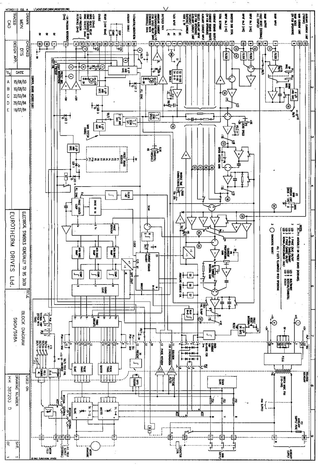
55
56
57 7.0 BASIC SETTING UP AND OPERATING INSTRUCTIONS 7.1 PRESET ADJUSTMENT DESCRIPTION Check the preset potentiometer settings on the larger plug-in card which is accessible under the front cover. The potentiometers are normally factory set to positions which will provide adequate performance in most load/controller configurations. It is recommended that initially the presets are left in these positions and that fine tuning of the system is done, if necessary, at the end of the commissioning process. The one exception to this is the main current limit preset; note the setting of this control and then turn it fully anticlockwise. The initial setting of the presets should thus be as follows: POT No. DESCRIPTION NORMAL INITIAL SETTING 1 Setpoint ramp up rate Clockwise rotation gives more rapid acceleration. 2 Setpoint ramp down rate Clockwise rotation gives more rapid deceleration. 3 Zero speed It should not be necessary to adjust this initially on a new factory tested drive. 4 Standstill threshold Sets low speed drive quench level if the standstill logic switch S8/2 is set to the on position. Clockwise sets lower speed. 5 Speed Proportional Clockwise increases speed loop gain 6 Speed Integral Clockwise decreases speed loop integral time constant. 7 Main Current Limit Clockwise increases current limit up to max. 200% FLC* short-term overload. 8 Current Proportional Clockwise increase current loop gain. 9 Current Integral Clockwise decreases current loop integral time constant. 10 Speed Calibration Clockwise increases motor speed. 11 Field Field Voltage O/P clockwise increases output voltage (see S9/4) Midway Midway About midway Midway 20% Clockwise 20% Clockwise Fully anti-clockwise (Zero current) Midway Fully anti-clockwise About midway Fully anti-clockwise 7-1
58 7.2 OPTION SWITCHES There are two user selectable option switches S8 and S9, which are located under the lower flap of the control board. Selection should only be made when the controller is isolated. S8/1 BUFFERED CURRENT SIGNAL (terminal 27) UP = ON = Armature current meter reads ± Amps. For applications employing a centre-zero meter. DOWN = OFF = Meter reads modulus. For applications employing a uni-directional meter. DEFAULT:ON NOTE: In 546 and 548 units the Armature Current Meter will always read + Amps, regardless of the setting of switch S1, since these convertors cannot produce negative output current. S8/2 STANDSTILL LOGIC UP = ON = Standstill logic enabled. This will disable the drive whenever the Total Setpoint is zero and the speed is below the standstill threshold set by P4. DOWN = OFF = Standstill logic inoperative. DEFAULT:OFF S8/3 SETPOINT RAMP CONNECTION UP = ON = Setpoint Ramp Output internally summed with Input No. 1 and Input No. 2. DOWN = OFF = Setpoint Ramp Output internally disconnected from the summing amplifier (but still available at terminal 8). DEFAULT:ON S8/4 SETPOINT RAMP RANGE UP = ON = Setpoint ramp rate adjustable from 0.25 to 7.5 seconds. DOWN = OFF = Setpoint ramp rate adjustable from 2.5 to 75 seconds. DEFAULT:OFF S8/5 HEALTH LATCH ENABLE UP = ON = Prevents drive restart when fault condition removed (eg, on over-current reset, or motor thermistor reset, drive will not automatically restart) To allow drive to restart, terminal 34 (start) must be taken low (eg, 0V). DOWN = OFF = Drive restarts automatically on fault reset. DEFAULT:ON S8/6 EXTERNAL RAMP RESET UP = ON = Setpoint ramp reset by either drive quench or terminal 6 to 0V. DOWN = OFF = Setpoint ramp reset only by terminal 6 to 0V (allows external use of setpoint ramp). DEFAULT: ON S8/7 CONTACTOR DROP OUT ON OVER- CURRENT UP = ON = Contactor does not drop out on over-current trip (this can prevent burning of contactor poles in certain configurations). DOWN = OFF = Contactor drops out on over-current. DEFAULT: OFF S8/8 TACH FILTER (10ms time constant) UP = ON = Tach filter of 10ms time constant applied to the speed feedback to attempt to remove tach ripple. Note that this option will have a destabilising effect on the speed loop stability and a reduction in speed loop gain P5, may be required. DOWN = OFF = No tach filter. DEFAULT: OFF S9/1 HALF WAVE FIELD SUPPLY UP = ON = Half wave rectification field supply. Typically using 415V single phase supply the field voltage will be 180V DC nominal.* DOWN = OFF = No field supply from this option. DEFAULT: OFF 7-2

59 S9/2 FULL WAVE FIELD SUPPLY UP = ON = Full wave rectification field supply. Typically using 415V single phase supply the field voltage will be 360V DC nominal.* DOWN = OFF = No field supply from this option. DEFAULT: ON S9/3 3 PHASE HALF WAVE FIELD SUPPLY ON = UP = 3 phase half wave field supply. Typically when operating from 3 phase 460/480V supply the field voltage will be 300V DC nominal.* DOWN = OFF = No field supply from this option DEFAULT: OFF * If more accurate field voltage setting is required, refer to option switch S9/4 and P11. S9/4 ADJUSTABLE FIELD SUPPLY ON = UP = Adjustable field supply used in conjunction with P11. The adjustment range is typically from 10% to 100% of full wave rectification. OFF = DOWN = No field supply form this option. DEFAULT: OFF S9/5 FIELD FAILURE OVER-RIDE ON = UP = Field failure condition over-ridden, typically when operating with a permanent magnet motor, or a shunt machine with very low field current, the field failure alarm is made inactive. DOWN = OFF = Field failure alarm active. DEFAULT: OFF S9/6 RESERVED DEFAULT: OFF (Factory set) S9/7 2Q/4Q OPERATION ON = UP = 2 Quadrant operation only, for use with 591A and 599A products. DOWN = OFF = 4 Quadrant operation only for use with 590A and 598A products. DEFAULT: Factory set (NOTE: No malfunction will occur if S9/7 is left off on any product). S9/8 RESERVED DEFAULT: ON (Factory set) 7-3
Model ER-340XRi / ER-680XRi / ER-1220XRi DC drive product manual HG iss 9 1
 Model ER-340XRi / ER-680XRi / ER-1220XRi DC drive product manual HG102909 iss 9 1 This drive is an isolated 4 Quadrant speed controller for shunt wound or permanent magnet motors. It utilises speed feedback
Model 340i / 680i / 1220i DC drive product manual HG iss 8 1
 Model 340i / 680i / 1220i DC drive product manual HG102938 iss 8 1 Sprint Electric Limited, Arundel, UK Tel. +44 (0)1903 730000 Fax. +44 (0)1903 730893 Email. info@sprint-electric.com www.sprint-electric.com
Tension Control Unit Type Product Manual EUROTHERM DRIVES. Copyright Eurotherm Drives Limited Printed in England HA Issue 3
 EUROTHERM DRIVES Control Unit Type 5525 Product Manual Copyright Eurotherm Drives Limited 2003 All rights strictly reserved. No part of this document may be stored in a retrieval system, or transmitted
RE-PR3-E-86&105 3-Phase Panel Mount 86 and 105kW
 Page 1 of 6 3-Phase Panel Mount 86 and 105kW Features: Benefits: 0-10Vdc, 0-5Vdc, 4-20mA or manual via potentiometer control input Over temperature protection with auto reset Enclosed panel mounting Efficient
RE-PR1-F 1-Phase Din-Rail Mount 1.5, 3 & 6kW
 Page 1 of 5 RE-PR1-F 1-Phase Din-Rail Mount 1.5, 3 & Features: Benefits: 0-10Vdc or 0-5Vdc control input Over temperature protection with auto reset Din-rail mounting Efficient electronic switching No
Burden Fuse Rating Resistor SAF / SAK6 1NM 10mm M8 12NM SAF / SAK10 2NM 16mm M8 12NM
 Contents Section Page 1.0 Introduction 1 2.0 Specification 1-4 3.0 Installation 5-8 4.0 Programming 9-10 5.0 Menus 10-12 6.0 Fault Finding/Diagnostics 12-13 7.0 Communication 13 8.0 Setting Up 13-16 1.0
User Guide 4Q kW D.C.Motor Regenerative Speed Controller. Part Number: Issue Number: 3
 User Guide 4Q2 0.55-7.5kW D.C.Motor Regenerative Speed Controller Part Number: 0400-0042-03 Issue Number: 3 General Information The manufacturer accepts no liability for any consequences resulting from
Dycon D2430 EN54-4 Fire Alarm Power Supply Series
 Dycon D2430 EN54-4 Fire Alarm Power Supply Series Technical Description Installation and Operating Manual Construction Product Regulation 0359-CPR-00434 Page 1 of 14 Contents 1. General... 3 1.1 Product
EUROTHERM ONTROLS. Two phase thyristor power switches. Product data
 TC2000 TC2001 EUROTHERM ONTROLS Two phase thyristor power switches Product data TC2000 TC2001 Thyristor power switches Compact, two phase thyristor power switches for electrical heating applications from
Fincor DC Drives. Flexible & Powerful TYPICAL APPLICATIONS. Conveyor Rugged. Extruder Reliable. Conveyor Simple. Mixer Flexible
 DC Drives Flexible & Powerful single-phase DC drives provide a complete family solution from the compact Series 2120 chassis drive to the powerful Series 2230 and it s feature rich application specific
RVS-AX Instruction Manual
 RVS-AX Analog Soft Starter 8-170A, 220-600V Instruction Manual Ver. 10/11/2009 2 Table of Content RVS-AX Instruction Manual 1. TABLE OF CONTENT 1. Table of Content...2 2. Safety & Warnings...3 2.1 Safety...3
HIB Enclosed Inverter User Guide
 HIB Enclosed Inverter User Guide (0.75kW~22kW) V1.2.0 Contents 1 Safety information...1 2 Technical Data...2 3 Motor Connection...4 4 Operation...5 5 Single phase circuit diagram...7 6 Three phase circuit
2122H. Arm Field Arm Field 1/8-1/ / /8-1/ / / /
 Non-Regen Drives Non-regenerative drives are typically used on applications which primarily motor in one direction and stopping is achieved through friction or infrequent use of a dynamic braking resistor.
Fincor Series 2230 MKII/2240
 Fincor Series 2230 MKII/ Fincor Series 2200 regenerative drives are ideal for your more demanding applications. They feature flexibility with ratings up to 5 horsepower. The Series 2230 MKII offers new
Thyristor power controller TE10A. Burst-firing Single-cycle Advanced Single-cycle
 Thyristor power controller TE10A Burst-firing Single-cycle Advanced Single-cycle Control of short-wave infrared elements and loads of constant resistance up to 20kW User Manual Copyright Eurotherm Automation
MaxPak Plus Analog DC V S Drive
 Three-Phase 3-600 HP non-regenerative and 5-150 HP regenerative drives Designed to accommodate a wide range of industrial requirements, the DC V S Drive has been widely applied worldwide. Selected ratings
SDS Enclosed Star-Delta Starter User Guide
 SDS Enclosed Star-Delta Starter User Guide (7.5kW~90kW) V2.0.0 PLEASE NOTE: AS STANDARD AND UNLESS OTHERWISE SPECIFIED, THIS PRODUCT IS EQUIPPED WITH A BASIC LOW INTEGRITY EMERGENCY STOP CIRCUIT STOPPING
SOLSTART Instruction Manual
 Solstart Analog Soft Starter 8-58A, 220-600V Instruction Manual Ver. 23/03/2009 2 Table of Content SOLSTART Instruction Manual 1. TABLE OF CONTENT 1. Table of Content...2 2. Safety & Warnings...3 2.1 Safety...3
MAXIMUM OUTPUT AC SUPPLY INPUT SPEED RANGE USER ADJUSTMENT EXTERNAL CONTROL CONTROL ACTION INSTALLATION
 1 DRM050IR / DRM100I / DRM200IR DC Motor Controller Product Manual This drive is an isolated single direction speed controller for shunt wound or permanent magnet motors. It utilizes speed feedback from
1/6 through 5 HP Adjustable Speed, DC Motor Controllers
 1/6 through 5 HP Adjustable Speed, DC Motor Controllers 1/6-5 HP 115 or 230 V, Single Phase - Reconnectable Four Quadrant Regenerative Selectable Deadband AC Line Starting DC Tachometer Feedback Run Contact
512C Series. Product Manual EUROTHERM DRIVES. HA Issue 7. ! Copyright Eurotherm Drives Limited 2001
 EUROTHERM DRIVES 512C Series Product Manual HA389196 Issue 7! Copyright Eurotherm Drives Limited 2001 All rights strictly reserved. No part of this document may be stored in a retrieval system, or transmitted
Open Chassis Star-Delta Starter User Guide
 Open Chassis Star-Delta Starter User Guide (7.5kW~90kW) V2.0.1 Contents 1 Safety information... 1 2 Technical Data... 2 3 Supply & Motor Connections & Circuit Diagrams... 5 4 Control Connections & Operation...
& HIGH CURRENT DC POWER SUPPLIES INSTRUCTION MANUAL
 72-6850 & 72-6852 HIGH CURRENT DC POWER SUPPLIES INSTRUCTION MANUAL Table of Contents Introduction 2 Specification 2 Safety 4 EMC 5 Installation 6 Connections 6 Operation 7 Maintenance and Repair 8 www.tenma.com
506/507/508. Product Manual. HA Issue 13. Copyright 2013 Parker Hannifin Manufacturing Ltd. WARRANTY
 506/507/508 Product Manual HA389427 Issue 13 Copyright 2013 Parker Hannifin Manufacturing Ltd. All rights strictly reserved. No part of this document may be stored in a retrieval system, or transmitted
HE-PSU(4.0) Power Supply & Battery Charger Installation, Commissioning & Operating Manual
 Power Supply & Battery Charger Installation, Commissioning & Operating Manual") HE-PSU(4.0) Power Supply & Battery Charger Installation, Commissioning & Operating Manual Page 1 of 10 CONTENTS 1. GENERAL...2 2. POWER REQUIREMENTS...2 2.1 HE-PSU(4.0) Input/Output Electrical Ratings...2
HE-PSU(4.0) Power Supply & Battery Charger Installation, Commissioning & Operating Manual Page 1 of 10 CONTENTS 1. GENERAL...2 2. POWER REQUIREMENTS...2 2.1 HE-PSU(4.0) Input/Output Electrical Ratings...2
MODEL 520 REMOTE START ENGINE MANAGEMENT SYSTEM
 MODEL 520 REMOTE START ENGINE MANAGEMENT SYSTEM DSE 520 ISSUE 4 4/4/02 MR 1 TABLE OF CONTENTS Section Page INTRODUCTION... 4 CLARIFICATION OF NOTATION USED WITHIN THIS PUBLICATION.... 4 1. OPERATION...
SECTION MOTOR CONTROL
 SECTION 26 24 19 MOTOR CONTROL PART 1 - GENERAL 1.1 SECTION INCLUDES A. Manual motor starters B. Magnetic motor starters C. Combination magnetic motor starters D. Solid-state reduced voltage motor starters
TOWER MAXI T SINGLE CONVERSION ON LINE UPS SYSTEMS
 INSTRUCTION MANUAL TOWER MAXI T SINGLE CONVERSION ON LINE UPS SYSTEMS September 2000 TOWER UPS DISTRIBUTION (PTY) LTD 1 1. INTRODUCTION T A B L E O F C O N T E N T S 1.1 General Description... 3 1.2 Features...
ATS22D88Q soft starter-ats22-control 220V-power 230V (22kW)/ V(45kW)
/ V(45kW)") Product datasheet Characteristics ATS22D88Q soft starter-ats22-control 220V-power 230V (22kW)/400...440V(45kW) Complementary Assembly style Function available Supply voltage limits Main Range of product
Product datasheet Characteristics ATS22D88Q soft starter-ats22-control 220V-power 230V (22kW)/400...440V(45kW) Complementary Assembly style Function available Supply voltage limits Main Range of product
Power thyristor units. 460 series. Control of single-phase resistive and inductive loads. User Manual
 Power thyristor units 460 series Control of single-phase resistive and inductive loads User Manual Copyright Eurotherm Automation 1996 All rights reserved. All reproduction or transmission in any form
RVS-DN Digital Reduced Voltage Motor Starter
 RVS-DN Digital Reduced Voltage Motor Starter Specification Guide Specification Guide Contents 1.0 Introduction 2.0 Specifications 2.1 Standard Performance Features 2.2 Standard Protection Features 2.3
INTER PLANT STANDARD - STEEL INDUSTRY THYRISTOR CONVERTORS FOR ARMATURE AND FIELD OF MAIN DRIVE MOTORS. Corresponding IS does not exist
 INTER PLANT STANDARD - STEEL INDUSTRY IPSS THYRISTOR CONVERTORS FOR ARMATURE AND FIELD OF MAIN DRIVE MOTORS Corresponding IS does not exist IPSS: 1-10-038-08 0 FOREWORD 0.1 This Inter Plant Standard has
Application Description
 -14 Type, Intelligent Technologies (IT.) Soft Starters February 2007 Contents Description Page Type, Intelligent Technologies (IT.) Soft Starters Product Description....... -14 Application Description....
User Manual. Solar Charge Controller 3KW
 User Manual Solar Charge Controller 3KW 1 CONTENTS 1 ABOUT THIS MANUAL... 3 1.1 Purpose... 3 1.2 Scope... 3 1.3 SAFETY INSTRUCTIONS... 3 2 INTRODUCTION... 4 2.1 Features... 4 2.2 Product Overview... 5
Dycon D1532SM. EN50131/PD6662 Grade 3, 12V 2A Power Supply. Technical Description Installation and Operating Manual DYCON POWER SOLUTIONS LTD
 Dycon D1532SM EN50131/PD6662 Grade 3, 12V 2A Power Supply Technical Description Installation and Operating Manual DYCON POWER SOLUTIONS LTD Tel: +44 (0)1443 471 900 Unit A Cwm Cynon Business Park Mountain
Observe all necessary safety precautions when controlling the soft starter remotely. Alert personnel that machinery may start without warning.
 Introduction OPERATING INSTRUCTIONS: MCD REMOTE OPERATOR Order Codes: 175G94 (for MCD 2) 175G361 + 175G9 (for MCD 5) 175G361 (for MCD 3) 1. Introduction 1.1. Important User Information Observe all necessary
USERS MANUAL MCD REMOTE OPERATOR
 USERS MANUAL MCD REMOTE OPERATOR Order Code: 175G9004, 175G3061 Contents Contents Introduction...2 Important User Information...2 General Description...2 Symbols Used in this Manual...2 Installation...3
University of Houston Master Construction Specifications Insert Project Name SECTION ELECTRONIC VARIABLE SPEED DRIVES PART 1 - GENERAL
 SECTION 23 04 10 ELECTRONIC VARIABLE SPEED DRIVES PART 1 - GENERAL 1.1 RELATED DOCUMENTS: A. The Conditions of the Contract and applicable requirements of Division 1, "General Requirements", and Section
1.1 Caution Statements
 USER MANUAL 1.1 Caution Statements Caution Statements cannot cover every potential cause of equipment damage but can highlight common causes of damage. It is the installer's responsibility to read and
ACC Series Power Conditioner OPERATION & INSTALLATION MANUAL
 ACC Series Power Conditioner OPERATION & INSTALLATION MANUAL PHASETEC digital power conditioners are designed to safely operate electrical equipment in the harshest power quality environments. With a wide
Cutler-Hammer. Installation Instructions for the Digitrip OPTIM Pole Trip Unit Installation and Operation with L-Frame Series C Circuit Breakers
 Cutler-Hammer Installation Instructions for the Digitrip OPTIM 550 3-Pole Trip Unit Installation and Operation with L-Frame Series C Circuit Breakers Table of Contents Description Page 1.0 General Information......................1
(with Class-1 AC resistive load) 3. G3PB-215B-2N-VD kW max. (25 A) G3PB-225B-3N-VD 2. G3PB-225B-2N-VD kw max. (35 A) G3PB-235B-3N-VD 2
 3. G3PB-215B-2N-VD kW max. (25 A) G3PB-225B-3N-VD 2. G3PB-225B-2N-VD kw max. (35 A) G3PB-235B-3N-VD 2") Solid-state Contactor (New Heat Sink Construction) G3PB Space and working time saved with new heat sink construction. Series now includes 480-VAC models to allow use in a greater range of applications.
Solid-state Contactor (New Heat Sink Construction) G3PB Space and working time saved with new heat sink construction. Series now includes 480-VAC models to allow use in a greater range of applications.
EPS/ELA-Series User Manual EPS/ELA 250W
 EPS/ELA-Series User Manual EPS/ELA 250W EPS Stromversorgung GmbH Tel: +49 (0)821 570451 0 Index 3 Page: 1 Table of contents: Page 1. Features of ELA-Series... 3 1.1 Basic Functions... 3 1.2 Options...
EC200 ELECTRONIC CONTROL SYSTEM
 1 INTRODUCING THE EC200 ELECTRONIC CONTROL SYSTEM With the use of new technology and an innovative approach to user interfacing, the EC200 Power Control System provides a complete control solution for
Dimensions WxHxD [mm] Weight [kg]
![Dimensions WxHxD [mm] Weight [kg]](/thumbs/96/128790851.jpg "Dimensions WxHxD [mm] Weight [kg]") SPECIFICATIONS The SOLSTART electronic soft starter incorporates two sets of thyristors (Two phase control) to start a threephase squirrel cage induction motor and an internal bypass. By supplying a slowly
SPECIFICATIONS The SOLSTART electronic soft starter incorporates two sets of thyristors (Two phase control) to start a threephase squirrel cage induction motor and an internal bypass. By supplying a slowly
2.1 Warnings & Agency Approvals Electrical Connections - Specifications Standard Wiring Configurations...2 4
 CHAPTER ELECTRICAL 2 INSTALLATION Contents of this Chapter... 2.1 Warnings & Agency Approvals..................2 2 2.1.1 Isolation..............................................2 2 2.1.2 Electrical Power
Unified requirements for systems with voltages above 1 kv up to 15 kv
 (1991) (Rev.1 May 2001) (Rev.2 July 2003) (Rev.3 Feb 2015) (Corr.1 June 2018) Unified requirements for systems with voltages above 1 kv up to 15 kv 1. General 1.1 Field of application The following requirements
Instruction Manual. Harmonic Filter AHF 005/010. Drives Solutions
 Harmonic Filter AHF 005/010 Instruction Manual Drives Solutions Contents Safety... 2 Warnings... 2 Symbols used in this manual... 2 Operator s safety... 2 Avoid filter module damage... 2 DC-link resonance...
The Z Series. SCR Power controllers for resistance heating applications. Zero-Fired SCR Power Controllers AMPS VAC
 The Z Series Zero-Fired SCR Power Controllers 60-1200 AMPS 120-600 VAC SCR Power controllers for resistance heating applications. ROBICON 1996 Rev. 7/96 Applications Robicon s Z series power controls are
A1P OPERATING MANUAL
 A1P OPERATING MANUAL TABLE OF CONTENTS Introduction... p. 2 Features... p. 2 Description... p. 3 Theory of Operation... p. 3 Installation... p. 4 Electrical Connections... p. 5 Options... p. 6 Warranty...
MCD 200 Series Soft Starters
 MCD 200 Series Soft Starters AC motors often cause one or more serious problems during startup acceleration. MCD 200 Series electronic soft starters control motor current to provide a smooth start. When
OPERATING AND MAINTENANCE MANUAL. Primary Current Injection Test Set. 750ADM-H mk2
 OPERATING AND MAINTENANCE MANUAL Product: Type: Primary Current Injection Test Set 750ADM mk2 750ADM-H mk2 DESIGNED AND MANUFACTURED BY: T & R Test Equipment Limited 15-16 Woodbridge Meadows, Guildford,
Appendix: Safety and application notes for... 15
 Contents Safety... 2 Warnings... 2 Symbols used in this manual... 2 Operator s safety... 2 Avoid filter module damage... 2 DC-link resonance... 2 Description... 3 Description... 3 Ordering numbers, 380-415
1 Phase electronic contactor (SC 1)
") 1 Phase electronic contactor (SC 1) - Rated operational voltage up to 600VAC 50/60 Hz - Rated operational current up to 15/30A/50/63A AC-1 - Control voltage from or - Compact modular design 22.5, 45, or
1 Phase electronic contactor (SC 1) - Rated operational voltage up to 600VAC 50/60 Hz - Rated operational current up to 15/30A/50/63A AC-1 - Control voltage from or - Compact modular design 22.5, 45, or
Compact Sine Inverter
 Compact Sine Inverter Instructions for installation & use Applies to the following models: Output power: 700watt, 1000 watt, 1500watt, 2000 watt & 3000 watts Output voltage: and output, 50Hz & 60Hz Output
506/507/508. Product Manual WARRANTY. HA Issue 10. Copyright 2007 Parker SSD Drives, a division of Parker Hannifin Ltd.
 506/507/508 Product Manual HA389427 Issue 10 WARRANTY Parker SSD Drives warrants the goods against defects in design, materials and workmanship for the period of 12 months from the date of delivery on
K25000 & KD25000 Series
 K25000 & KD25000 Series Fire Alarm Power Supplies Installation, Commissioning and Operating Manual Man-1128 Issue 14 January 2016 Man-1128_K25400_series_Power_Supply_Manual_14 Page 1 of 20 Section Page
825-P Modular Protection System for motors Specification Guide
 Specification Guide 1.0 General 1.01 The motor protection relay shall have a current operating range of 0.5 and 5000 amperes. 1.02 The motor protection relay shall provide current measurement-based protection
512C Series. Product Manual EUROTHERM DRIVES. HA Issue 7. ! Copyright Eurotherm Drives Limited 2001
 EUROTHERM DRIVES 512C Series Product Manual HA389196 Issue 7! Copyright Eurotherm Drives Limited 2001 All rights strictly reserved. No part of this document may be stored in a retrieval system, or transmitted
MAKING MODERN LIVING POSSIBLE. Quick Setup VLT FCM 300 Series. Phone: Fax: Web: -
 MAKING MODERN LIVING POSSIBLE Quick Setup VLT FCM 300 Series Factory setting Motors type B14 & B34 mounting Reset (pushbutton) Start Jog Speed reference Fig. 1 - Reset to be closed short time for resetting
User Manual Solar Charge Controller 3KW
 User Manual Solar Charge Controller 3KW Version: 1.3 CONTENTS 1 ABOUT THIS MANUAL... 1 1.1 Purpose... 1 1.2 Scope... 1 1.3 SAFETY INSTRUCTIONS... 1 2 INTRODUCTION... 2 2.1 Features... 2 2.2 Product Overview...
Presentation Soft starters 0 Altistart 48 soft start - soft stop units
 Presentation Soft starters 5 6 7 65_Ver.-EN.fm/ Presentation (continued) Soft starters Applications The Altistart 8 soft start - soft stop unit is a controller with 6 thyristors which is used for the torque-controlled
Installation, Operation and Maintenance Manual. EVC Controller (from February 2007)
") Installation, Operation and Maintenance Manual (from February 2007) Publication 2698C (GB) 0207 1A 3319 8035B Donaldson reserve the right to alter design without notice. Freedom from patent restrictions
Installation, Operation and Maintenance Manual (from February 2007) Publication 2698C (GB) 0207 1A 3319 8035B Donaldson reserve the right to alter design without notice. Freedom from patent restrictions
Features. Description. Table of Contents
 Features Very low profile Very high efficiency (typically 90%) Single and dual output versions Input voltages from 24V to 110VDC nominal voltages from 5V to 48VDC -40 C to +71 C operation without de-rating
A. Provide variable frequency drives to operate variable torque loads as shown on the Drawings and as specified herein.
 DIVISION 23 HEATING, VENTILATING, AND AIR CONDITIONING (HVAC) SECTION 23 90 71 PART 1 GENERAL 1.01 DESCRIPTION A. Provide variable frequency drives to operate variable torque loads as shown on the Drawings
WF-5110R True Sine Wave Inverter
 Operator s Manual WF-5110R True Sine Wave Inverter WF-9900 Series WF-5110R ( The Inverter model number is located on the label on top of the enclosure) Distributed in the U.S.A. and Canada by ARTERRA DISTRIBUTION
Model Number Structure
 Solid State Relays (Single-phase) G3PB New Single-phase Solid State Relays with Compact Size for Heater Control Slim models with a thickness of only 22.5 mm are also available. Compact design achieved
17429X.00 SERIES MODELS:
 LEESON ELECTRIC MOTORS, GEARMOTORS AND DRIVES R User s Manual 17429X.00 SERIES MODELS: 174298.00 174299.00 PWM REGENERATIVE DC TO DC DRIVES II Table of Contents 17429X.00 Drives...............................................................
DENVER PUBLIC SCHOOLS DESIGN AND CONSTRUCTION STANDARDS This Standard is for guidance only. SECTION MOTORS, STARTERS & DRIVES
 PART 0 DESIGN STANDARDS 0.01 GENERAL DESIGN GUIDELINES A. Coordinate starter needs for mechanical equipment prior to 50% CD and confirm again for 100% CD submittal. B. Coordinate temperature controls requirements
Phoenix DX Sensorless AC Vector Drive. 3 HP to 3500 HP
 Phoenix DX Sensorless AC Vector Drive 3 HP to 3500 HP Standard Features: * PRECISE CONTROL OF MOTOR SPEED AND TORQUE * BI-DIRECTIONAL FLYCATCHER (CATCH SPINNING MOTOR) * EASY TO USE, SIMPLE SETUP * POWER
Matrix APAX. 380V-415V 50Hz TECHNICAL REFERENCE MANUAL
 Matrix APAX 380V-415V 50Hz TECHNICAL REFERENCE MANUAL WARNING High Voltage! Only a qualified electrician can carry out the electrical installation of this filter. Quick Reference ❶ Performance Data Pages
DEVICE STATE/BYPASSED FAILURE OVERLOAD
 Technical specifications Type 5. 7. Control electronics Rated values Terminal Rated control supply voltage A1A2 V AC 115 230 115 230 Tolerance % -15+10-15+10 Rated control supply STANDBY ma 15 15 Rated
A3Z OPERATING MANUAL
 A3Z OPERATING MANUAL TABLE OF CONTENTS Introduction... p. 2 Features... p. 2 Description... p. 3 Theory of Operation... p. 3 Installation... p. 4 Electrical Connections... p. 5 Options... p. 6 Warranty...
Sorensen XG Series / XTR Series W A. 850 W, 1U Half Rack Programmable DC Power Supplies V
 Sorensen XG Series / XTR Series 670 850 W 850 W, 1U Half Rack Programmable DC Power Supplies 6 600 V Highest Power Density Comprehensive Digital and Analog Interface Options Scalable, Multi-Unit Design
A6Z OPERATING MANUAL
 A6Z OPERATING MANUAL TABLE OF CONTENTS Introduction... p. 2 Features... p. 2 Description... p. 3 Theory of Operation... p. 3 Installation... p. 4 Electrical Connections... p. 5 Options... p. 6 Warranty.p.
DUAL 60V 20A POWER FLEX POWER SUPPLY INSTRUCTION MANUAL
 72-7570 DUAL 60V 20A POWER FLEX POWER SUPPLY INSTRUCTION MANUAL Table of Contents Specification 1 Safety 3 EMC 4 Installation 5 Connections 5 Operation 6 Maintenance 8 Specification General specifications
NEMA 1, NEMA 4X and Chassis Mount Adjustable Speed Controls for DC Motors
 Made in the U.S.A. NEMA 1, NEMA 4X and Chassis Mount Adjustable Speed Controls for DC Motors Nema Enclosed DC Control Specifications Catalog Number BC140 or Features BC138 BC139 BC140-FBR BC154 BC160 BCWD140
The Power of Reliability INSTRUCTION MANUAL
 The Power of Reliability INSTRUCTION MANUAL SAFETY & WARNINGS Read this manual carefully and understand all Warnings and Cautions before connections are made to the Inverter. If unsure about any aspects
We reserve the right to alter data according to improvements made. Previous documents become invalid with the issue of this document.
 General information Actuator controls AC 01.2 for controlling multi-turn actuators of the SA/SAR type range and part-turn actuators of the SQ/SQR.2 type range. Features and functions Power supply Standard
ST - II Series POWER SUPPLIES USER INSTRUCTIONS
 Introduction ST - II Series POWER SUPPLIES These instructions detail the installation and operation requirements for the ST20-II & ST35-II power supplies. These have been designed for operation in RV s
MODEL 540 USER MANUAL INCORPORATING MODEL 530 TEMPERATURE CONTROLLER
 MODEL 540 USER MANUAL INCORPORATING MODEL 530 TEMPERATURE CONTROLLER Signal Group Limited 12 Doman Road, Camberley Surrey, GU15 3DF England Tel: +44 (0) 1276 682841 Fax: +44 (0) 1276 691302 e-mail: instruments@signal-group.com
Switching DC Power Supply
 99 Washington Street Melrose, MA 02176 Phone 781-665-1400 Toll Free 1-800-517-8431 Visit us at www.testequipmentdepot.com Model 1693, 1694 Switching DC Power Supply INSTRUCTION MANUAL 1 Safety Summary
CONTROL FEATURES AVAILABLE OPTIONS
 Vari Speed A2000 TABLE OF CONTENTS Control Features Options Application Data Operating Condition s Control Ratings Chart Mounting Dimensions Installation and Wiring Typical Wiring Diagram Schematic (Block
PSU EN54-4 Power Supplies
 PSU EN54-4 Power Supplies Ordering: Models, Sales Order Parts: PSU MXP-549 : 1.5A PSE in 7Ah enclosure MXP-550 : 3.0A PSE in 17/18Ah enclosure MXP-550D : 3.0A PSE in 25Ah enclosure MXP-551 : 5.0A PSE in
SAFTRONICS DF8 PLUS SERIES
 DF8 PLUS SERIES ¼ to 5 HP Full Wave Regenerative Reversing SCR Speed Controls for DC Motors CAUTION Equipment is at possibly lethal AC line voltage when AC power is connected. Pressing the STOP pushbutton
RESIDUAL CURRENT CIRCUIT BREAKER
 Quality Features Mid Trip - Different knob position to indicate whether the device is Switched OFF by a fault or Switched OFF manually Inscription Window - Ensures circuit identification and hence reduces
S4562C 1085 COMBI BOARD APPLICATION. Contents PRODUCT HANDBOOK. General
 S4562C 1085 COMBI BOARD APPLICATION PRODUCT HANDBOOK The S4562C 1085 combi board is an integration of an on/off temperature control and an electronic ignition control. The S4562C 1085 combi board is intended
590+DRV Series DC Digital Drive
 EUROTHERM DRIVES 590+DRV Series DC Digital Drive Product Manual HA470388U002 Issue 1 Copyright Eurotherm Drives Limited 2003 All rights strictly reserved. No part of this document may be stored in a retrieval
REVISED ATM72 Auto Transfer Module
 Capricorn Controls DA01ATM1-1 Data & Application Note Page 1 of 8 REVISED - - - ATM72 Auto Transfer Module Genset Controls - Timers - Monitors - Trips - Battery Charging - Spares & Accessories - Custom
AF series contactors (9 2650)
") R E32527 R E39322 contactors General purpose and motor applications AF series contactors (9 2650) 3- & 4-pole contactors General purpose up to 2700 A Motor applications up to 50 hp, 900 kw NEMA Sizes 00
R E32527 R E39322 contactors General purpose and motor applications AF series contactors (9 2650) 3- & 4-pole contactors General purpose up to 2700 A Motor applications up to 50 hp, 900 kw NEMA Sizes 00
SE-3SCR-LM MANUAL MOTOR LOAD MANAGER
 3714 Kinnear Place Saskatoon, SK Canada S7P 0A6 Ph: (306) 373-5505 Fx: (306) 374-2245 www.littelfuse.com/relayscontrols SE-3SCR-LM MANUAL MOTOR LOAD MANAGER MARCH 5, 2013 REVISION 4 MOTOR LOAD MANAGER
Product Overview. Product Identification. Amps One CT Two CTs Three CTs
 AH06 (optional mounting bracket for small, medium, and large CTs) DANGER HAZARD OF ELECTRIC SHOCK, EXPLOSION, OR ARC FLASH Follow safe electrical work practices. See NFPA 70E in the USA, or applicable
VEM motors Thurm GmbH
 VEM motors Thurm GmbH Installation, Operating and Maintenance Instructions Single-Phase Squirrel-Cage Induction Motors, Standard Version March 2005 1. General To avoid damage to the motors and equipment
DEEP SEA ELECTRONICS PLC
 COMPLEX SOLUTIONS MADE SIMPLE. DEEP SEA ELECTRONICS PLC DSE710 AUTOSTART CONTROL MODULE OPERATING MANUAL Deep Sea Electronics Plc Highfield House Hunmanby North Yorkshire YO14 0PH ENGLAND Sales Tel: +44
Cobra 3 Stand-By Emergency Central Lighting Inverter (CLI) Technical Specifications
 Technical Specifications") Cobra 3 Stand-By Emergency Central Lighting Inverter (CLI) Technical Specifications PART 1 GENERAL 1.1 SUMMARY A. This specification describes a stand-by, three-phase, solid state Lighting Inverter System
Cobra 3 Stand-By Emergency Central Lighting Inverter (CLI) Technical Specifications PART 1 GENERAL 1.1 SUMMARY A. This specification describes a stand-by, three-phase, solid state Lighting Inverter System
RVS-DX Digital Reduced Voltage Motor Starter
 RVS-DX Digital Reduced Voltage Motor Starter Specification Guide Specification Guide Contents 1.0 Introduction 2.0 Specifications 2.1 Standard Performance Features 2.2 Standard Protection Features 2.3
Compact System NRGS 11-2 NRGS Original Installation Instructions English
 Compact System NRGS 11-2 NRGS 16-2 EN English Original Installation Instructions 810366-05 1 Contents Important Notes Page Usage for the intended purpose...4 Safety note...4 LV (Low Voltage) Directive
THREE PHASE DC DRIVES
 World class in design World beating in function Find out more: www.sprint-electric.com Sprint Electric Ltd. Rudford Industrial Estate, Ford, Arundel, West Sussex, U.K. BN18 OBD Tel: +44 (0)1903 730000
Types of Motor Starters There are several types of motor starters. However, the two most basic types of these electrical devices are:
 Introduction Motor starters are one of the major inventions for motor control applications. As the name suggests, a starter is an electrical device which controls the electrical power for starting a motor.
Appendix: Safety and application notes for 19
 Contents Safety 2 Warnings 2 Symbols used in this manual 2 Operator's safety 2 Avoid filter module damage 2 DC-link resonance 2 Description 3 Description 3 Ordering numbers, 380-415 V, 50 Hz 4 Ordering