Tension Control Unit Type Product Manual EUROTHERM DRIVES. Copyright Eurotherm Drives Limited Printed in England HA Issue 3
|
|
|
- Madeline Summers
- 5 years ago
- Views:
Transcription
1 EUROTHERM DRIVES Control Unit Type 5525 Product Manual Copyright Eurotherm Drives Limited 2003 All rights strictly reserved. No part of this document may be stored in a retrieval system, or transmitted in any form or by any means to persons not employed by a Eurotherm group company without written permission from Eurotherm Drives Ltd. Although every effort has been taken to ensure the accuracy of this document it may be necessary, without notice, to make amendments or correct omissions. Eurotherm Drives cannot accept responsibility for damage, injury, or expenses resulting therefrom. Printed in England HA Issue 3
2 WARRANTY Eurotherm Drives warrants the goods against defects in design, materials and workmanship for the period of 12 months from the date of delivery on the terms detailed in Eurotherm Drives Standard Conditions of Sale IA058393C. Eurotherm Drives reserves the right to change the content and product specification without notice. COPYRIGHT in this document is reserved to Eurotherm Drives Ltd. INTENDED USERS This manual is to be made available to all persons who are required to configure, install or service the equipment described herein or any other associated operation.
3 Warnings and Instructions Only qualified personnel who thoroughly understand the operation of this equipment and any associated machinery should install, start-up or attempt maintenance of this equipment. Noncompliance with this warning may result in personal injury and/or equipment damage. Never work on any control equipment without first isolating all power supplies from the equipment. The drive motor must be connected to an appropriate safety earth. Failure to do so presents an electrical shock hazard. This equipment was tested before it left our factory. However, before installation and start-up, inspect all equipment for transit damage, loose parts, packing materials etc. This product conforms to IP20 protection. Due consideration should be given to environmental conditions of installation for safe and reliable operation. THESE WARNINGS AND INSTRUCTIONS ARE INCLUDED TO ENABLE THE USER TO OBTAIN THE MAXIMUM EFFECTIVENESS AND TO ALERT THE USER TO SAFETY ISSUES PRODUCT MANUAL: This manual is intended to provide a description of how the product works. It is not intended to describe the apparatus into which the product is installed. This manual is to be made available to all persons who are required to design an application, install, service or come into direct contact with the product. APPLICATIONS ADVICE: Applications advice and training is available from Eurotherm Drives Ltd.
4 INSTALLATION: Ensure that mechanically secure fixings are used as recommended. Ensure that cables and wire terminations are as recommended and clamped to required torque. Ensure that the installation and commissioning of this product are carried out by a competent person. APPLICATION RISK: The integration of this product into other apparatus or systems is not the responsibility of Eurotherm Drives Ltd as to its applicability, effectiveness or safety of operation or of other apparatus or systems. Where appropriate the user should consider some aspects of the following risk assessment. RISK ASSESSMENT: Under fault conditions or conditions not intended. 1. The motor speed may be incorrect. 2. The motor speed may be excessive. 3. The direction of rotation may be incorrect. 4. The motor may be energised (unless the installation specifically prevents unexpected or unsequenced energisation of the motor). In all situations the user should provide sufficient guarding to prevent risk of injury and/or additional redundant monitoring and safety systems. NOTE: During power loss the product will not operate as specified. MAINTENANCE: Maintenance and repair should only be performed by competent persons using only the recommended spares (or return to factory for repair). Use of unapproved parts may create a hazard and risk of injury. WHEN REPLACING A PRODUCT IT IS ESSENTIAL THAT ALL USER DEFINED PARAMETERS THAT DEFINE THE PRODUCT'S OPERATION ARE CORRECTLY INSTALLED BEFORE RETURNING TO USE. FAILURE TO DO SO MAY CREATE A HAZARD AND RISK OF INJURY. PACKAGING: The packaging is combustible and if disposed of in this manner incorrectly may lead to the generation of toxic fumes which are lethal. REPAIRS: Repair reports can only be given if sufficient and accurate defect reporting is made by the user. Remember, the product without the required precautions can represent an electrical hazard and risk of injury, and that rotating machinery is a mechanical hazard and risk of injury. PROTECTIVE INSULATION: 1. All exposed metal insulation is protected by basic insulation and bonding to earth i.e. Class NOTE: Earth bonding is the responsibility of the installer. 3. All signal terminals are protected by double insulation, i.e. Class 2 insulation. The purpose of this protection is to allow safe connection to other low voltage equipment and is not designed to allow these terminals to be connected to any unisolated potential. 4. Single fault conditions.
5 TENSION CONTROL UNIT TYPE 5525 Contents Chapter 1 General Chapter 2 Control System Type Control Unit Standard Features Chapter 3 Technical Details Chapter 4 Control for use with Centre Winders to Provide Constant /Taper Control Commissioning Procedure & Product Code Chapter 5 Centre Winder Characteristics Scaling Build up ratio Chapter 6 Circuit Diagrams Control Unit Type 5525 Cont.-1
6 Chapter 1 General The Eurotherm Drives type 5525 Control Unit is designed to provide accurate tension control of materials during winding by DC motor powered centre winders. The Controller would normally operate in conjunction with an Eurotherm Drives single phase or 3-phase thyristor motor controller, although operation with other motor controllers is possible providing that independent torque and speed control reference inputs are available. The type 5525 unit is extremely flexible in operation and is applicable to winding systems in a variety of processing industries such as plastics, paper, film, wire, metal strip, etc. The compact size of the 96mm DIN package and the comprehensive integrated control circuitry with built-in power supplies, make the 5525 extremely easy to install and simple to set up. Control Unit Type
7 Chapter 2 Control System CENTRE WINDER WITH TYPE 5525 TENSION CONTROL SYSTEM MATERIAL FLOW CENTRE WINDER MATERIAL LINE SPEED SIGNAL REDUCTION GEAR TYPE 5525 TENSION CONTROL UNIT DC MOTOR TACHO WINDER SPEED SIGNAL TORQUE PROGRAMMING REFERENCE DC MOTOR SPEED LIMIT REFERENCE DC MOTOR FIELD (CONST.) DC MOTOR SPEED/TORQUE CONTROLLER STATIC FRICTION COMP. DYNAMIC FRICTION COMP. MAX. DIAMETER RATIO SETTING TENSION TAPER SETPOINT TENSION SETPOINT PRESET CONTROLS OPERATOR SETTING CONTROLS Control Unit Type
8 The 5525 Controller operates by programming the torque applied by a DC motor to a centre wind drive system during reel build-up. The tension of material passing onto the periphery of a centre winder depends upon the torque applied by the motor to the winder centre shaft and the instantaneous diameter of the reel. With constant torque applied, the material tension will decrease proportionally with reel diameter as the reel builds up. To maintain a constant tension in the wound material it is therefore necessary to increase the shaft torque proportionately as the reel diameter increases. It is possible to achieve constant control of tension throughout a winding cycle providing that the applied torque can be continuously regulated in proportion to the reel diameter. By continuously monitoring signals of material line speed and winder speed, the 5525 controller calculates reel diameter and provides a torque control reference to the motor controller. Accurate operation can be achieved over a wide range of material line speeds and build-up ratios. Additional circuit facilities in the controller provide a continuously variable amount of taper tension, so that light tapers may be introduced to give only small deviation from constant tension from beginning to end of a wind; or alternatively severe tapers may be introduced to reduce the material tension to virtually zero at the end of a wind. It should be noted that the tension and taper controls are completely non-interactive. It should be noted that this unit is not capable of controlling tension at zero speed. If this facility is required, stall tension or diameter memory methods should be incorporated into the system. 2-2 Control Unit Type 5525
9 TYPE 5525 Control Unit Standard Features * Static friction compensation. * Dynamic friction compensation. * Taper tension (tension either increasing or decreasing as reel diameter increases). * Minimum diameter offset. F Radius R The 5525 Control Unit is designed to provide tension control of material wound onto DC motor operated centre winders. N R N L Torque T Continuous calculation of reel diameter enables the unit to programme the torque reference of a DC motor controller to provide any tension/diameter winding profile. Reel torque T = F x Radius R Radius R is proportional to (Line Speed) N (Reel Speed) N L R giving T is proportional to F x N N L R But T is proportional to the armature current IA in a DC motor with constant field, hence IA is proportional to F x N N L R Control Unit Type
10 Chapter 3 Technical Details Supply - 1 phase, 110/115V, 50/60Hz 220/240V, 50/60Hz Line Speed Input - +10V DC Internal scaling is necessary for non-standard input voltages. (see scaling section). Winder Speed Input - +10V DC Internal scaling is necessary for non-standard input voltages (see scaling section). Output Torque Control Signal - 0 to +10 Volts DC or 0 to -10 Volts DC Max/Min. Diameter ratio - Up to 20 to 1. Maximum ambient temperature - 50 o C. Control by - Diameter Computation. Diameter ratio ranges: between 1 and 5:1 between 5 and 10:1 between 10 and 20:1 Control Modes - Constant. - Taper. External Connection for - setting potentiometers. setting controls - Taper tension setting potentiometer. - Manual speed limit potentiometer. External connections for pre set - Static friction compensation. controls - Dynamic friction compensation. - Minimum diameter offset. Mechanical - Panel mounting 96mm x 96mm DIN standard. Overall length 165mm. Panel cut out 92 x 92mm +.8mm -.0mm. Options - Plug-in sleeve. control operator station with all setting controls. Control Unit Type
11 Chapter 4 Control for use with Centre Winders to Provide Constant /Taper Control COMMISSIONING PROCEDURE & PRODUCT CODE The basic DC drive must be operating correctly, i.e., motor rotation, speed and current scaling, before the tension control system can be commissioned. The basic drive commissioning procedure is detailed in the relevant drive manual. 1. Check the tension control unit specification label that all details are correct, i.e., Supply voltage Line speed reference volts Winder Speed reference volts. Build up ratio coded as follows (5525/--/--/xxx/-- xxx = 101 Ratio between 1 and 5: 1 xxx = 102 Ratio between 5 and 10: 1 xxx = 103 Ratio between 10 and 20: Product Code Field Block 1 4 digits specifying basic product Control Unit Field Block 2 Output Type 01 Positive going 02 Negative going Field Block 3 Power Supply V V V V Field Block 4 3 digits specifying build up range. 101 Build up ratio 1:1 to 5:1 102 Build up ratio 5:1 to 10:1 103 Build up ratio 10:1 to 20:1 Field Block 5 Options 00 Standard unit 01 Plug-in unit 2. Thoroughly check out all external wiring. - Power connections - Line and winder tachogenerator connections. - Drive connections. - Preset and operator control connections. The wiring should be checked against the system connection diagram supplied with the tension control system. 3. Connect the supply to the tension control unit and check the following voltages. Terminal 32 with regard to 30 Supply volts 110/240V AC. Terminal 17 with regard to V DC. Terminal 2 with regard to 18-10V DC. The following tests should be carried out without any web on the line or winder. Control Unit Type
12 4. Start the line drive and check the voltage on terminal 21 with regard to 18 is approximately +10V DC at full winder speed (it may be necessary to turn up the tension setting potentiometer while running the line at full speed to achieve full winder speed). If either signal is of the opposite polarity the relevant tachogenerator connection must be reversed. If the signal is of the wrong value the tachogenerator voltage should be checked if too high rescale tension controller (see scaling section). 5. Set the taper potentiometer and the friction compensation presets to zero. With the line running at full speed adjust the winder speed, with the tension control or speed limit control if provided, to give equal peripheral speed on the line and the winder core. Monitor terminal 31 with regard to 18 and adjust the minimum diameter offset potentiometer for zero volts. If it is impossible to match line and winder peripheral speed, the minimum diameter offset potentiometer should be preset as follows: Code 1012V on terminal 27 with regard to V on terminal 27 with regard to V on terminal 27 with regard to With the line running at full speed monitor terminal 20 with regard to 18 and check that the voltage increases as the winder speed decreases in proportion to the simulated diameter build up. If the taper control is set to maximum the voltage will remain constant equivalent to minimum diameter irrespective of winder speed. 7. Frictional losses compensation. With the line and winder running, set the tension control to zero. when the winder is at rest, slowly turn up the static compensation preset until the winder just rotates. This compensates for the static friction or stiction. Turn the dynamic friction preset fully up. Turn up the set tension control until the winder is running at more than half speed then turn back fully. Slowly turn down the dynamic friction preset until the speed starts to fall, adjust so that the speed very slowly runs down. This compensates for the dynamic friction or rolling resistance. NOTE: It may be necessary to re-adjust these settings from time to time as mechanical conditions change. 8. Ensure that the surface speed of an empty core on the rewind exceeds the line speed by about 10% across the speed range of the line. 9. Thread web on to the line and winder and run the complete line setting tension and taper controls for optimum winding. 4-2 Control Unit Type 5525
13 Chapter 5 Centre Winder Characteristics 1. Constant Torque Motor Torque Material Min Reel Diameter Max Min Reel Diameter Max 2. Constant Motor Torque Material Min Reel Diameter Max Min Reel Diameter Max Control Unit Type
14 3. Taper (-)ve - (Constant to Constant Torque). Constant Motor Torque Constant Material Taper Taper Constant Torque Constant Torque Min Reel Diameter Max Min Reel Diameter Max 4. Taper (-)ve - (Below Constant Torque Characteristic). Constant Torque Motor Torque Material Constant Torque Tapers Decreasing below Constant Torque Min Reel Diameter Max Min Taper Reel Diameter Max 5. Taper (+)ve - Increasing. Motor Max Torque Increasing + ve Taper Max Motor Max Torque Line Increasing Motor Torque Constant Material Constant Min Reel Diameter Max Min Reel Diameter Max 5-2 Control Unit Type 5525
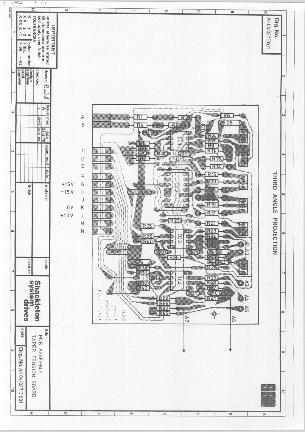
15 Scaling If the line or winder tachogenerator signals are not as specified on the 5525 tension control unit, it will be necessary to rescale as follows: Remove the unit lid and unplug the tension printed circuit card (see diagram). Line volts: scaling resistors R1 and R2, select R1 + R2 in kilohms is equal to the value in volts of the line tachogenerator at full speed. Winder volts: scaling resistors R4 and R5, select R4 and R5 in kilohms is equal to the value in volts of the winder tachogenerator at full speed. Fine adjustment of the scaling is possible using potentiometer P1 for line volts and P2 for winder volts but this is not essential. Build up ratio If the maximum diameter build up ratio exceeds the coded specification, resistor R13 will have to be changed. Ratio between 1 and 5 : 1 R13 = 3K9 Ratio between 5 and 10 : 1 R13 = 9K1 Ratio between 10 and 20 : 1 R13 = 18K Note: Since R13 and R14 provide an attenuation network to allow for build up ratio, it is the relative values of these two resistors which is important. There is therefore an alternative set of resistor values which provide the same performance as those detailed above. Build Up R13 R14 5 : 1 9K1 2K2 10 : 1 9K1 1K 20 : 1 9K1 470R Control Unit Type
16
17
18
19
20
21
22 ISS. MODIFICATION ECN No. 1 Initial Issue DATE DRAWN CHK'D 2 Amendments and up-dating sales and service addresses GDR 3 Re-typed manual in "Word". Changed SSD to Eurotherm Drives. Replaced AH045639D001 Issue 2 with Issue FEP FIRST USED ON MODIFICATION RECORD EUROTHERM DRIVES 5525 Product Manual DRAWING NUMBER ZZ C SHT OF KE04300C ISSUE 3 IA ISSUE ARTWORKER /A Control Unit Type
23
24 SALES & SERVICE EUROTHERM DRIVES, a division of Eurotherm International Group of Companies, provides sales and service capability worldwide through Eurotherm Drives Companies, Eurotherm Group Companies and Agents. Head Office Eurotherm Drives Limited New Courtwick Lane Littlehampton West Sussex BN17 7PD Tel: (01903) Telex: Fax: (01903)
CPW Current Programmed Winder for the 890. Application Handbook. Copyright 2005 by Parker SSD Drives, Inc.
 CPW Current Programmed Winder for the 890. Application Handbook Copyright 2005 by Parker SSD Drives, Inc. All rights strictly reserved. No part of this document may be stored in a retrieval system, or
Thyristor power controller TE10A. Burst-firing Single-cycle Advanced Single-cycle
 Thyristor power controller TE10A Burst-firing Single-cycle Advanced Single-cycle Control of short-wave infrared elements and loads of constant resistance up to 20kW User Manual Copyright Eurotherm Automation
Model ER-340XRi / ER-680XRi / ER-1220XRi DC drive product manual HG iss 9 1
 Model ER-340XRi / ER-680XRi / ER-1220XRi DC drive product manual HG102909 iss 9 1 This drive is an isolated 4 Quadrant speed controller for shunt wound or permanent magnet motors. It utilises speed feedback
Single Phase Electronic Speed Controllers
 Single Phase Electronic Speed Controllers Installation and Wiring Instructions Stock Ref. N 10303103A 3A SPEED CONTROLLER ELECTRONIC 1PH 10303106A 6A SPEED CONTROLLER ELECTRONIC 1PH Rating: 220-240V ~
EUROTHERM ONTROLS. Two phase thyristor power switches. Product data
 TC2000 TC2001 EUROTHERM ONTROLS Two phase thyristor power switches Product data TC2000 TC2001 Thyristor power switches Compact, two phase thyristor power switches for electrical heating applications from
Time Electronics DC Voltage Calibrator. Technical Manual
 Time Electronics 1010 DC Voltage Calibrator Technical Manual V1.1 20/04/09 Time Electronics Ltd Botany Industrial Estate, Tonbridge, Kent, TN9 1RH Tel: +44(0)1732 355993 Fax: +44(0)1732 770312 Email: mail@timeelectronics.co.uk
MODEL 540 USER MANUAL INCORPORATING MODEL 530 TEMPERATURE CONTROLLER
 MODEL 540 USER MANUAL INCORPORATING MODEL 530 TEMPERATURE CONTROLLER Signal Group Limited 12 Doman Road, Camberley Surrey, GU15 3DF England Tel: +44 (0) 1276 682841 Fax: +44 (0) 1276 691302 e-mail: instruments@signal-group.com
Time Electronics DC Multifunction Voltage/Current/Resistance Calibrator. Technical Manual
 Time Electronics 1017 DC Multifunction Voltage/Current/Resistance Calibrator Technical Manual V1.2 01/11/10 Time Electronics Ltd Botany Industrial Estate, Tonbridge, Kent, TN9 1RH Tel: +44(0)1732 355993
506/507/508. Product Manual WARRANTY. HA Issue 10. Copyright 2007 Parker SSD Drives, a division of Parker Hannifin Ltd.
 506/507/508 Product Manual HA389427 Issue 10 WARRANTY Parker SSD Drives warrants the goods against defects in design, materials and workmanship for the period of 12 months from the date of delivery on
512C Series. Product Manual EUROTHERM DRIVES. HA Issue 7. ! Copyright Eurotherm Drives Limited 2001
 EUROTHERM DRIVES 512C Series Product Manual HA389196 Issue 7! Copyright Eurotherm Drives Limited 2001 All rights strictly reserved. No part of this document may be stored in a retrieval system, or transmitted
User Guide 4Q kW D.C.Motor Regenerative Speed Controller. Part Number: Issue Number: 3
 User Guide 4Q2 0.55-7.5kW D.C.Motor Regenerative Speed Controller Part Number: 0400-0042-03 Issue Number: 3 General Information The manufacturer accepts no liability for any consequences resulting from
Model 340i / 680i / 1220i DC drive product manual HG iss 8 1
 Model 340i / 680i / 1220i DC drive product manual HG102938 iss 8 1 Sprint Electric Limited, Arundel, UK Tel. +44 (0)1903 730000 Fax. +44 (0)1903 730893 Email. info@sprint-electric.com www.sprint-electric.com
5001TCP SPEED CONTROLLER
 INSTALLATION AND SETTING UP MANUAL 5001TCP SPEED CONTROLLER WARNING Disconnect all incoming power before working on this equipment. Follow power lockout procedures. Use extreme caution around electrical
512C Series. Product Manual EUROTHERM DRIVES. HA Issue 7. ! Copyright Eurotherm Drives Limited 2001
 EUROTHERM DRIVES 512C Series Product Manual HA389196 Issue 7! Copyright Eurotherm Drives Limited 2001 All rights strictly reserved. No part of this document may be stored in a retrieval system, or transmitted
506/507/508. Product Manual. HA Issue 13. Copyright 2013 Parker Hannifin Manufacturing Ltd. WARRANTY
 506/507/508 Product Manual HA389427 Issue 13 Copyright 2013 Parker Hannifin Manufacturing Ltd. All rights strictly reserved. No part of this document may be stored in a retrieval system, or transmitted
5001TCP SPEED CONTROLLER
 VARIABLE SPEED DRIVE CONTROLLER INSTALLATION AND SETTING UP MANUAL 5001TCP SPEED CONTROLLER With PC101 Torque Limit Control WARNING Disconnect all incoming power before working on this equipment. Follow
Tension Control Inverter
 Tension Control Inverter MD330 User Manual V0.0 Contents Chapter 1 Overview...1 Chapter 2 Tension Control Principles...2 2.1 Schematic diagram for typical curling tension control...2 2.2 Tension control
Technical Description
 Technical Description LUL, 73 Stock Refurbishment Heating, Ventilating & Air-conditioning Multi-stage Thermostat for Saloon 0.1 19-May-02 ISSUED FOR DISCUSSION FK DC Rev. Date Description By Check Copyright
Super Calendar. Heated rolls
 Application Assistant Surface Winders are used to roll up material such as wire, paper, film, metals and textiles. The surface winding method applies the driving power to a fixed diameter roll or rolls,
Monicon Instruments Co., Ltd. CHR-1285/2485 CHR-1285/2485 BATTERY CHARGER
 CHR-1285/2485 BATTERY CHARGER TEL:886-4-2238-0698 FAX:886-4-2238-0891 Web Site:http://www.monicon.com.tw E-mail:sales@monicon.com.tw Copyright 2007 Monicon Instruments Co., Ltd. All right reserved. Contents
A Member of the. Integrated Metering Technologies
 I n s t a l l a t i o n M a n u a l A Member of the Integrated Metering Technologies 1.0 General and safety Do not install, operate or maintain this flow meter without reading, understanding and followingthe
SPECTRA ENGINEERING PTY LTD. MXPS15 Series Technical Manual
 SPECTRA ENGINEERING PTY LTD MXPS15 Series Technical Manual MXPS15 Series Spectra Engineering Pty Ltd ABN 65 057 696 438 9 Trade Road Malaga Western Australia 6090 Tel: +61-8-92482755 Fax: +61-8-92482756
TRIPS AND FAULT FINDING
 WWW.SDS.LTD.UK 0117 9381800 Trips and Fault Finding Chapter 6 6-1 TRIPS AND FAULT FINDING Trips What Happens when a Trip Occurs When a trip occurs, the drive s power stage is immediately disabled causing
Super Calendar. Heated rolls
 Application Report Surface Winders are used to roll up material such as wire, paper, film, metals and textiles. The surface winding method applies the driving power to a fixed diameter roll or rolls, on
Rental Industry Safety Tester Safe Check 5s
 Rental Industry Safety Tester Safe Check 5s Feb 2006 2006 Clare Instruments Inc. Issue 2.0 Firmware Version : 1.2a Limited Warranty & Limitation of Liability Clare Instruments Inc, guarantees this product
SAFTRONICS DF8 PLUS SERIES
 DF8 PLUS SERIES ¼ to 5 HP Full Wave Regenerative Reversing SCR Speed Controls for DC Motors CAUTION Equipment is at possibly lethal AC line voltage when AC power is connected. Pressing the STOP pushbutton
A WARNING GIVES THE READER INFORMATION WHICH IF DISREGARDED COULD CAUSE INJURY OR DEATH
 EUROTHERM DRIVES 590A SERIES THREE PHASE CONVERTORS PRODUCT MANUAL A WARNING GIVES THE READER INFORMATION WHICH IF DISREGARDED COULD CAUSE INJURY OR DEATH All rights strictly reserved. No part of this
Maximum 20 ma, 24 VDC 825 ohms (see section 3.3) Supply voltage dependence
 Supply voltage dependence") ALPHASENSE USER MANUAL Page 1 4-20mA Transmitter for Oxygen Sensors 072-0126 Issue 2 1 INTRODUCTION The Transmitter PCB includes circuitry for an electrochemical oxygen sensor to convert the µa output
ALPHASENSE USER MANUAL Page 1 4-20mA Transmitter for Oxygen Sensors 072-0126 Issue 2 1 INTRODUCTION The Transmitter PCB includes circuitry for an electrochemical oxygen sensor to convert the µa output
OPERATOR S MANUAL Please read all the information in this booklet before using the unit.
 TECHNE UCAL400 + Calibrator OPERATOR S MANUAL Please read all the information in this booklet before using the unit. Unit Serial number: 4/02 Issue 1 TECHNE is a registered Trademark of Techne Incorporated.
2-PHASE STEPPING MOTOR DRIVER FE Z5 DISPENSE
 2-PHASE STEPPING MOTOR DRIVER FE Z5 DISPENSE For Diaphragm Dosing Pumps FEM 1.02_.55 / FEM 1.09_.55 Controller board package, without pump: ID 160536 Operating and Installation Manual It is important to
Good Winding Starts the First 5 Seconds Part 2 Drives Clarence Klassen, P.Eng.
 Good Winding Starts the First 5 Seconds Part 2 Drives Clarence Klassen, P.Eng. Abstract: This is the second part of the "Good Winding Starts" presentation. Here we discuss the drive system and its requirements
A Member of the. Integrated Metering Technologies
 I n s t a l l a t i o n M a n u a l A Member of the Integrated Metering Technologies 1.0 General and Safety Do not install, operate or maintain this flow meter without reading, understanding and followingthe
Boston Gear Ratiotrol DC Motor Speed Control
 Boston Gear Ratiotrol DC Motor Speed Control P-3017-BG Doc. No. 60007 Installation and Operation DCX plus Series II Enclosed Models 1/12-1 HP a division of Altra Industrial Motion Contents l General Information
Power thyristor units. 460 series. Control of single-phase resistive and inductive loads. User Manual
 Power thyristor units 460 series Control of single-phase resistive and inductive loads User Manual Copyright Eurotherm Automation 1996 All rights reserved. All reproduction or transmission in any form
Part 1. PL / PLX Digital DC Drive. Part 2 APPLICATION BLOCKS. Part 2 Application Blocks. Part 3 High Power Modules PL / PLX
 1 PL / PLX Digital DC Drive Part 2 APPLICATION BLOCKS Part 1 PL / PLX Digital DC Drive Part 2 Application Blocks Part 3 High Power Modules PL / PLX 275-980 HG102635 V6.00a 2 Contents 3 NOTE. These instructions
3000W HF/PFC Battery Charger
 3000W HF/PFC Battery Charger Description Advanced high frequency switching design with 92% typical efficiency Fully sealed enclosure providing improved reliability in demanding environments > 0.98 Power
SB 2000 PUSH TO SEARCH NEXT STAG E. Aerotech, Inc. FORM: QM 1320
 Inlet Controller SB 2000 USER'S MANUAL AUTO OPEN MANUAL PUSH TO SEARCH NEXT STAG E CLOSE Aerotech, Inc. FORM: QM 1320 4215 Legion Dr. Mason, MI 48854-1036 USA Rev. 3, Sept. 1997 Ph. (517) 676-7070 Fax
MAGPOWR Spyder-Plus-S1 Tension Control
 MAGPOWR TENSION CONTROL MAGPOWR Spyder-Plus-S1 Tension Control Instruction Manual Figure 1 EN MI 850A351 1 A COPYRIGHT All of the information herein is the exclusive proprietary property of Maxcess International,
Filtered PWM Speed Control for Permanent Magnet DC Motors
 Instructions for Installation and Operation Filtered PWM Speed Control for Permanent Magnet DC Motors Model 0794 Speed and Direction Control up to 5/8 HP NEMA-1/IP-20 Specifications Product Type:... WPM-2148E1
Center Winder Specification
 Center Winder Specification Bump Roll Edge Guide Photo Eye 2000 Ft/ Min Dancer Arm Center Winder Overview Winding is simply a rotational means to take up and package material for more efficient handling
RCP200 Series Motor Controls. Instruction Manual Model RCP Model RCP Model RCP202-BC1 Model RCP202-BC2 Model RCP205-BC2
 RCP200 Series Motor Controls Instruction Manual Model RCP202-000 Model RCP205-000 Model RCP202-BC1 Model RCP202-BC2 Model RCP205-BC2 You ve just purchased the best! Congratulations! You ve just purchased
Operator Instructions for Tension Links
 Operator Instructions for Tension Links Page 1 of 9 Table of Contents Introduction... 3 Markings CE... 3 Electromagnetic Compatibility (EMC)... 3 Tension Link Type/Model Number... 3 Supplier... 3 Service...
DC POWER SUPPLY ALIMENTATION C.C.
 DC POWER SUPPLY ALIMENTATION C.C. ISO-TECH IPS 303A 201-3424 ISO-TECH IPS 601A 201-3446 SAFETY TERMS AND SYMBOLS These terms may appear in this manual or on the product: WARNING. Warning statements identify
Elcometer Motorised Film Applicator
 English Elcometer 4340 Motorised Film Applicator Operating Instructions R English This product meets the Electromagnetic Directive, Low Voltage Directive and the Machinery Directive. The product is Class
HIB Enclosed Inverter User Guide
 HIB Enclosed Inverter User Guide (0.75kW~22kW) V1.2.0 Contents 1 Safety information...1 2 Technical Data...2 3 Motor Connection...4 4 Operation...5 5 Single phase circuit diagram...7 6 Three phase circuit
Digital Intelligent Battery Charger OPERARATOR S MANUAL
 Digital Intelligent Battery Charger OPERARATOR S MANUAL WARNING! Before you install and use your Nitro Battery Charger, be sure to read and save these safety instructions. INTRODUCTION The Sinergex Nitro
HEAVY DUTY BATTERY BOOSTERS / CHARGER MODEL No. BC420N
 HEAVY DUTY BATTERY BOOSTERS / CHARGER MODEL No. BC420N OPERATING & MAINTENANCE INSTRUCTIONS 1206 SPECIFICATIONS Supply Voltage 230 Max Charge (Amps) 60 (cont) Max Boost (Amps) 400 Boost/Charge (Volts)
RE-PR3-E-86&105 3-Phase Panel Mount 86 and 105kW
 Page 1 of 6 3-Phase Panel Mount 86 and 105kW Features: Benefits: 0-10Vdc, 0-5Vdc, 4-20mA or manual via potentiometer control input Over temperature protection with auto reset Enclosed panel mounting Efficient
PSU EN54-4 Power Supplies
 PSU EN54-4 Power Supplies Ordering: Models, Sales Order Parts: PSU MXP-549 : 1.5A PSE in 7Ah enclosure MXP-550 : 3.0A PSE in 17/18Ah enclosure MXP-550D : 3.0A PSE in 25Ah enclosure MXP-551 : 5.0A PSE in
Installation, Operation and Maintenance Manual. EVC Controller (from February 2007)
") Installation, Operation and Maintenance Manual (from February 2007) Publication 2698C (GB) 0207 1A 3319 8035B Donaldson reserve the right to alter design without notice. Freedom from patent restrictions
Installation, Operation and Maintenance Manual (from February 2007) Publication 2698C (GB) 0207 1A 3319 8035B Donaldson reserve the right to alter design without notice. Freedom from patent restrictions
TABLE OF CONTENTS STANDARD FEATURES
 65E10 CONTROL SERIES CONTROLS Instruction Manual For DC Input Variable Speed Controls P.0. Box 10 5000 W. 106th Street Zionsville, Indiana 46077 Phone (317) 873-5211 Fax (317) 873-1105 www.dartcontrols.com
This section is specifically about safety matters
 6 4 ) 1 6 4 1 -, 1 8-4 6-4 1 6 4 7 + 6 1 ) 7 ) - -, - - + 6. 4 ) 6 J E? A Thank you for choosing this Mitsubishi transistorized Inverter option. This instruction manual gives handling information and precautions
Operating Manual. Pantographs. Version 05/12.
 Operating Manual Pantographs Version 05/12 Parts & Features A pantograph is a mechanical device that enables a load to be suspended by the means of balancing the load with two or more constant tension
Burden Fuse Rating Resistor SAF / SAK6 1NM 10mm M8 12NM SAF / SAK10 2NM 16mm M8 12NM
 Contents Section Page 1.0 Introduction 1 2.0 Specification 1-4 3.0 Installation 5-8 4.0 Programming 9-10 5.0 Menus 10-12 6.0 Fault Finding/Diagnostics 12-13 7.0 Communication 13 8.0 Setting Up 13-16 1.0
Tension Control Systems
 Technical Considerations Tension Zones I. tension zone in a web processing machine is defined as that area between which the web is captured, or isolated. Virtually any machine can be broken down into
Compact System NRGS 11-2 NRGS Original Installation Instructions English
 Compact System NRGS 11-2 NRGS 16-2 EN English Original Installation Instructions 810366-05 1 Contents Important Notes Page Usage for the intended purpose...4 Safety note...4 LV (Low Voltage) Directive
OMEGA. Separator Units. Standen Engineering Limited. Hereward Works, Station Road, Ely, Cambridgeshire. CB7 4BP England.
 OMEGA Separator Units Standen Engineering Limited. Hereward Works, Station Road, Ely, Cambridgeshire. CB7 4BP England. Tel: 01353 661111 www.standen.co.uk Fax: 01353 662370 IMPORTANT This operator s handbook
Pro Booster 802Li. Please read and fully understand the instructions in this manual before operation. Keep this manual safe for future reference.
 Please dispose of packaging for the product in a responsible manner. It is suitable for recycling. Help to protect the environment, take the packaging to the local amenity tip and place into the appropriate
Electropneumatic Converters i/p Converters Type 6111 Mounting and Operating Instructions EB 6111 EN
 Electropneumatic Converters i/p Converters Type 6111 Fig. 1 Type 6111 in standard version Fig. Type 6111 mounted on a supply air manifold Fig. 3 Type 6111 in field enclosure Mounting and Operating Instructions
DALI 650mA LED Driver
 Installation Guide DGLC650C18DD PATENT PENDING REGISTERED DESIGN Designed in Australia to meet Australian Standards and installation conditions DIGINET.NET.AU Diginet Control Systems Pty Ltd ABN 89 095
SERVO MOTORS BRUSHLESS SERVO MOTORS OPERATING INSTRUCTIONS 2016
 SERVO MOTORS BRUSHLESS SERVO MOTORS OPERATING INSTRUCTIONS 2016 3009/16 en Ed.02.2016 Read these Operating Instructions before performing any transportation, installation, commissioning, maintenance or
R231 A.V.R. Installation and maintenance R 231. This manual is to be given to. the end user. Armature 6- Field. Slow-blow fuse 250V 8 A
 Armature 6- Field This manual is to be given to the end user F1 Slow-blow fuse 250V 8 A 110 0V E+ E- 75 mm 140 mm P1 P2 Voltage Stability R 231 This manual concerns the alternator which you have just purchased.
PFC W HF/PFC Battery Charger
 PFC 5000 5000W HF/PFC Battery Charger Description Advanced high frequency switching design with 92% typical efficiency Fully sealed enclosure providing improved reliability in demanding environments >
WATER METERS OCTAVE ULTRASONIC WATER METER INSTALLATION & USER GUIDE
 WATER METERS OCTAVE ULTRASONIC WATER METER INSTALLATION & USER GUIDE OCTAVE ULTRASONIC WATER METER INSTALLATION & USER GUIDE TABLE OF CONTENTS General Information...4 Warranty...4 Included Items...4 Operation...5
LC BATTERY CHARGER OPERATION & MAINTENANCE GUIDE
 LC BATTERY CHARGER OPERATION & MAINTENANCE GUIDE SENS part number: 101194 Document revision: D DCN number: 105128 Date: 3/23/2006 1840 Industrial Circle Longmont, CO 80501 Fax: 303-678-7504 Tel: 303-678-7500
Switching DC Power Supply
 99 Washington Street Melrose, MA 02176 Phone 781-665-1400 Toll Free 1-800-517-8431 Visit us at www.testequipmentdepot.com Model 1693, 1694 Switching DC Power Supply INSTRUCTION MANUAL 1 Safety Summary
Powerframes - Power Electronics
 Powerframes - Power Electronics 70 series The study of power electronic devices, motor drives and circuits is an essential part of any course on power electrical systems. The Series 70 Power Electronics
RE-PR1-F 1-Phase Din-Rail Mount 1.5, 3 & 6kW
 Page 1 of 5 RE-PR1-F 1-Phase Din-Rail Mount 1.5, 3 & Features: Benefits: 0-10Vdc or 0-5Vdc control input Over temperature protection with auto reset Din-rail mounting Efficient electronic switching No
HE-PSU(4.0) Power Supply & Battery Charger Installation, Commissioning & Operating Manual
 Power Supply & Battery Charger Installation, Commissioning & Operating Manual") HE-PSU(4.0) Power Supply & Battery Charger Installation, Commissioning & Operating Manual Page 1 of 10 CONTENTS 1. GENERAL...2 2. POWER REQUIREMENTS...2 2.1 HE-PSU(4.0) Input/Output Electrical Ratings...2
HE-PSU(4.0) Power Supply & Battery Charger Installation, Commissioning & Operating Manual Page 1 of 10 CONTENTS 1. GENERAL...2 2. POWER REQUIREMENTS...2 2.1 HE-PSU(4.0) Input/Output Electrical Ratings...2
MULTI-LANE HOT FOIL PRINTER FOR CFS
 MULTI-LANE HOT FOIL PRINTER FOR CFS OPERATOR INSTRUCTIONS PARTS LISTING Designed and manufactured by: OPEN DATE EQUIPMENT LIMITED PUMA TRADE PARK, 145 MORDEN ROAD, MITCHAM, SURREY, CR4 4DG. UNITED KINGDOM.
TA-05/C. Instruction and Operation Manual. valid for art.-no.: F-TA-05/C-ISO. (start at modification No. 1601)
") Instruction and Operation Manual valid for art.-no.: 10091 F-TA-05/C-ISO (start at modification No. 1601) valid for art.-no.: 10092 F-TA-05/C-Sh (start at modification No. 1601) CAUTION: As with any form
Instruction and Operation Manual valid for art.-no.: 10091 F-TA-05/C-ISO (start at modification No. 1601) valid for art.-no.: 10092 F-TA-05/C-Sh (start at modification No. 1601) CAUTION: As with any form
INSTRUCTION MANUAL FOR THE CLINICAL 50 CENTRIFUGE
 INSTRUCTION MANUAL FOR THE CLINICAL 50 CENTRIFUGE 82013-800 January 2006 INDEX PAGE 1. General Information... 2 1.1 Description... 2 1.2 Safety precautions to be observed before operating the centrifuge...
Reviewed: DD Month University Code of Practice for Electrical Safety. PART B - Design and Construction of Electrical Equipment within the University
 Safety Office Reviewed: 17 July 2012 Reviewed: DD Month University Code of Practice for Electrical Safety PART B - Design and Construction of Electrical Equipment within the University The purpose of this
24V 3A EN54 Ancillary Power Supply
 24V 3A EN54 Ancillary Power Supply Normal supply - green light on Fault condition - call Engineer Control relay - activated 3A Power Supply C-TEC Manufactured in England by C-Tec EN 54-4 : 1997 INSTALLATION
Short Form Guide. Unidrive SP. Part Number: Issue: 2.
 Short Form Guide Unidrive SP Part Number: 0471-0162-02 Issue: 2 General The manufacturer accepts no liability for any consequences resulting from inappropriate, negligent or incorrect installation or adjustment
650mA Phase Dimmable LED Driver
 Installation Guide DGLC650C18PD PATENT PENDING REGISTERED DESIGN Designed in Australia to meet Australian Standards and installation conditions DIGINET.NET.AU Diginet Control Systems Pty Ltd ABN 89 095
HILLSTONE DC LOAD BANK
 OPERATING MANUAL for HILLSTONE DC LOAD BANK Type ref. HLD 240 480 100 Serial No. M36771 ISSUE 1 1 CONTENTS Introduction page 3 Safety Considerations page 3 Connecting procedure page 4 Operating instructions
INSTALLATION & OPERATING MANUAL RW SERIES WALL-MOUNT RECTIFIERS
 INSTALLATION & OPERATING MANUAL RW SERIES WALL-MOUNT RECTIFIERS WWW.UNIPOWERTELECOM.COM Manual No. RW-1 2008 UNIPOWER Corp. 01/24/08 rw-man All Rights Reserved UNIPOWER Telecom, Division of UNIPOWER Corporation
James Hamilton Electrical Pty Ltd (Inc in Qld) A.C.N trading as. Power Drive Systems. Generator Control Specialists
 A.C.N trading as. Power Drive Systems. Generator Control Specialists") James Hamilton Electrical Pty Ltd (Inc in Qld) A.C.N. 010 848 389 trading as Power Drive Systems Generator Control Specialists 48A Ainsdale Street Telephone: 0500 800 225 P.O. Box 30 West Chermside, Qld
James Hamilton Electrical Pty Ltd (Inc in Qld) A.C.N. 010 848 389 trading as Power Drive Systems Generator Control Specialists 48A Ainsdale Street Telephone: 0500 800 225 P.O. Box 30 West Chermside, Qld
PLA Applications Module Product Manual. HG V5.14
 1 PLA Applications Module Product Manual. HG102764 V5.14 2 Contents and Introduction 3 NOTE. These instructions do not purport to cover all details or variations in equipment, or to provide for every possible
The Power of Reliability INSTRUCTION MANUAL
 The Power of Reliability INSTRUCTION MANUAL SAFETY & WARNINGS Read this manual carefully and understand all Warnings and Cautions before connections are made to the Inverter. If unsure about any aspects
Mclennan Servo Supplies Ltd. Bipolar Stepper Motor Translator User Handbook PM546
 Mclennan Servo Supplies Ltd. Bipolar Stepper Motor Translator User Handbook PM546 Mclennan Servo Supplies Ltd. Telephone: 01276 26146 Yorktown Industrial Estate FAX: 01276 23452 22 Doman Road Camberley
DynaCon Instruction Manual
 DynaCon Instruction Manual Table of Contents Technical Specification & Warranty.... 3 Construction, Benefits & Safe Operating Procedures... 4 Noise Levels... 5 Installation, Operation & Maintenance...
INSTRUCTION MANUAL FOR THE THERMOCOUPLE ATTACHMENT UNIT (TAU)
") INSTRUCTION MANUAL FOR THE THERMOCOUPLE ATTACHMENT UNIT (TAU) Model Number: 41756 (100 125Vac) 41757 (220 240Vac) Manufactured in the United Kingdom CONTENTS Chapter Page Specification 3 What the TAU does
INSTRUCTION MANUAL FOR THE THERMOCOUPLE ATTACHMENT UNIT (TAU) Model Number: 41756 (100 125Vac) 41757 (220 240Vac) Manufactured in the United Kingdom CONTENTS Chapter Page Specification 3 What the TAU does
Motive Power. Network Power. Chargers. Bloc Batteries. Accessories. Service
 The Eternity Technologies range is built using only the highest quality and most efficient production processes at our state-of-the-art manufacturing centre in the UAE. It is this innovation, modern design
Starting System DS-102 Series 200. Elmatik AS P.O.Box 309 NO-3471, Slemmestad T F
 Starting System DS-102 Series 200 Elmatik AS P.O.Box 309 NO-3471, Slemmestad T - +47 31 28 37 83 F - +47 31 28 37 93 www.elmatik.no post@elmatik.no CONTENT 1. INTRODUCTION 3 2. TECHNICAL SPECIFICATIONS
KD LV Motor Protection Relay
 1. Protection Features KD LV Motor Protection Relay Overload (for both cyclic and sustained overload conditions) Locked rotor by vectorial stall Running stall / jam Single phasing / Unbalance Earth leakage
SERIES 2335 SINGLE-PHASE ADJUSTABLE-SPEED DC MOTOR CONTROLLERS (1/6-2 HP)
") Rev. 02/97 SERIES 2335 SINGLE-PHASE ADJUSTABLE-SPEED DC MOTOR CONTROLLERS (1/6-2 HP) TABLE OF CONTENTS SECTION TITLE PAGE I GENERAL INFORMATION 1 Introduction 1 General Description 1 Model Types 1 Motor
Rev. 02/97 SERIES 2335 SINGLE-PHASE ADJUSTABLE-SPEED DC MOTOR CONTROLLERS (1/6-2 HP) TABLE OF CONTENTS SECTION TITLE PAGE I GENERAL INFORMATION 1 Introduction 1 General Description 1 Model Types 1 Motor
Rescue Pac. Please read and fully understand the instructions in this manual before operation. Keep this manual safe for future reference
 Please dispose of Packaging for the product in a responsible manner. It is suitable for recycling. Help to protect the environment, take the packaging to the local amenity tip and place into the appropriate
Designing Drive Systems for Low Web Speeds
 Designing Drive Systems for Low Web Speeds Web Tension Control at Low Speeds Very low web speeds can provide challenges to implementing drive systems with accurate tension control. UNWIND LOAD CELL COOLING
2 TONNE TROLLEY JACK
 2 TONNE TROLLEY JACK 61829 IMPORTANT: Please read these instructions carefully to ensure the safe and effective use of this product and save these instructions for future reference. This manual has been
Recommended Practices for Installation for EC Directive 2014/30/EU Relating to EMC
 Recommended Practices for Installation for EC Directive 2014/30/EU Relating to EMC 10/16 Supplement to Installation & Operating Manual Any trademarks used in this manual are the property of their respective
VOLT POT 1K R220. OPEN FOR 60 Hz STAB A.V.R. R220. Installation and maintenance
 VOLT POT 1K 110 0V E+ E- OPEN FOR 60 Hz STAB This manual concerns the alternator which you have just purchased. We wish to draw your attention to the contents of this maintenance manual. SAFETY MEASURES
SINAMICS DCM. DC Converter. Application SINAMICS DCM as field supply unit. Edition 04-6/2013. SINAMICS drives
 SINAMICS DCM DC Converter Application SINAMICS DCM as field supply unit Edition 04-6/2013 SINAMICS drives SINAMICS DCM Compact User Manual Legal information Warning notice system This manual contains notices
TOWER MAXI T SINGLE CONVERSION ON LINE UPS SYSTEMS
 INSTRUCTION MANUAL TOWER MAXI T SINGLE CONVERSION ON LINE UPS SYSTEMS September 2000 TOWER UPS DISTRIBUTION (PTY) LTD 1 1. INTRODUCTION T A B L E O F C O N T E N T S 1.1 General Description... 3 1.2 Features...
These operating instructions apply for: NCX 380 NCZ 300 NCX 480 NCZ 370 NCX 580 L NCZ 480 NCX 660 K NCZ 560 NCZ 660 NCZ 800
 Original instructions Operating Instructions for May 2010 Electric Internal Vibrators BA No. 1092E Series NCX and NCZ These operating instructions apply for: NCX 380 NCZ 300 NCX 480 NCZ 370 NCX 580 L NCZ
User Manual. Liquid Level Sensor. Unit 600 Ampress Park Lymington, Hampshire SO4 l SLW United Kingdom
 7010 Liquid Level Sensor User Manual Gill Sensors & Controls Limited Unit 600 Ampress Park Lymington, Hampshire SO4 l SLW United Kingdom Tel: +44 (0) 1590 613 900 Fax +44 (0) 1590 613 901 info@gillsc.com
7007 Loop Mate 2 Loop / Voltage / Current Simulator
 7007 Loop Mate 2 Loop / Voltage / Current Simulator User Manual Time Electronics Ltd Unit 11 Botany Industrial Estate Tonbridge, Kent, TN9 1RH Tel: 01732 355993 Fax: 01732 770312 E-Mail: mail@timeelectronics.co.uk
Assembly instruction APD 6-/7-way
 Seite 1 von 14 Fixed connector Jam nut receptacle Assembly instruction Free connector Fixed connector Flange receptacle APD-1AP6, 6-way for stamped contacts APD-1AP6-EP 6-way for press in contacts APD-1AP7-EP
Rotary feed-through DDF-S/-KS
 Translation of the Original Operating Manual Rotary feed-through DDF-S/-KS Assembly and Operating Manual Superior Clamping and Gripping Imprint Imprint Copyright: This manual remains the copyrighted property