CONVERSION KIT. Installation Manual Hard Case Electric Bike Kit W W W. English
|
|
|
- Cordelia Stokes
- 6 years ago
- Views:
Transcription

1 CONVERSION KIT Installation Manual Hard Case Electric Bike Kit W W W English Please read through carefully before beginning your conversion

2 Installation This build assumes some knowledge about building electric bike kits onto bikes; as such some simple aspects are only briefly covered. The battery unit is the first part to attach to the bike frame. The battery comes out of the box with two plates zip-tied to the bottom of the battery box, these ties are to be cut and the plates separated. The thin plate of the two is the controller mounting plate, inside the box are two small bolts that can be used to fix the controller to the controller plate as shown above. The battery also comes with an assortment of larger bolts in two length, these lengths are dependent on the overall diameter of the downtube and some trial and error may be required to determine the correct size for your bike. Select 4 bolts of equal length and place them beside the bike. The battery box can be inserted into the frame triangle and the bolts fed down through the holes in the battery box edge. These bolts will hold the battery in place and stop it from sliding off the bike. 2

3 Battery Installation The thicker plate of the two that was removed from the battery box initially is now required along with 4 locking nuts and 4 flat washers. The plate is mounted on the bottom side of the downtube and the bolts threaded through the holes of the plate with the nuts attached loosely. The battery should now be positioned to the right location on your downtube. Start by fastening one of the nuts until the plate starts to squeeze the downtube between the plate and base of battery pack. The bolts should be fastened from side to side to ensure that the plate tightens evenly to the tube. Once the fasteners have clamped the battery to the frame some minor adjustment can be made by tapping the frame up or down or sideways with a mallet. Once in the perfect position the nuts can be fastened tight to ensure the battery pack cannot move with firm pushing on the pack. With some builds the longest bolts may be slightly too long and the short bolts too short. To overcome this issue multiple washers can be added between the plate and fastening nuts. 3


4 Controller Installation The controller plate is now able to be fastened to the leftover studs protruding from the battery plate fixing. The controller is orientated with the plugs at the top of the bike so that the power connector has enough length to reach the battery and that the hall and phase wired are ideal length. Plug the battery plug into the battery housing and route the hall and phase wires along the downtube and towards the rear chainstay. 4

5 Motor Installation The controller and battery are now installed and it s now time to install the motor to the bike. The first step is to remove your existing wheel from the bike and swap the tyre and brake rotor from your old wheel to the new hub motor wheel. These steps can be shown in detail in our 1000W off-road kit manual if required. The freewheel can be added to the hub, It is important to note that because of the width of the hub motor the larger (7-8-9) speed freewheels can cause spacing issues. These larger freewheels can be added but the rear dropouts may need to be slightly spread to accommodate for the larger space taken by the freewheel. Ideally, 6speed freewheels fit the best. Shown below is a 6-speed freewheel on the Crystalyte (3600W/6500W Kits) motor. There is a spacer in the kits that can be placed on the freewheel side to space the 1st gear cog from the side of the motor place to limit the chance of the derailleur touching the side plate. 5

6 Wheel Installation With the tyre, brake rotor and freewheel in place on the new wheel the wheel can now be inserted into the dropouts of the bike. This is easiest done by wheeling the bike upside down and resting the seat and handlebars on the ground. Ensure that there is a washer on the inside of the dropouts and a washer on the outside between the nut and dropout. 6


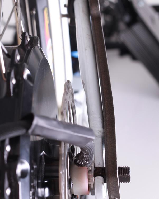
7 Torque Arm Installation The Torque arms are an essential component for kits that output extreme power. The Dillenger torque arms are designed to transfer the driving torque of the motor to a point on the frame that can withstand the torque as opposed to trying to hold substantial power through the small groove that is the dropout. The wheel is placed in the dropouts as per the previous steps, however before the wheel nut is installed the torque arm is slipped over the axle and pushed hard up against the dropout. The Dillenger torque arm out of the box is straight, however on normal chainstays there is some bend inwards towards the centre of the bike as the chainstay moves towards the bottom bracket. To accommodate for this some bending may be required in order to change the angle of the torque arm. This is demonstrated in the picture comparison below. 7
8 8


9 Once the torque arm is bent to the correct profile the torque arm can be slipped over the axle and placed in-line with the chainstay. The clamping plate is put along the inside of the chainstay and fastened to the torque arm with 4 bolts. These bolts are placed with 2 on the top of the chainstay and 2 on the bottom side of the chainstay. The bolts are fastened in order to secure the torque arm to the chainstay. 9


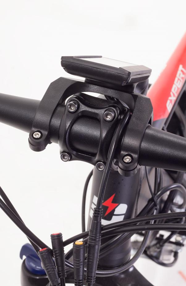
10 One of the two small bolts in the kit are fed through the axle clamp section of the torque arm and left loose. The axle nut can now be tightened to force the torque arm against the dropout. Once the axle nut is tight, the small axle clamping bolt and nut is fastened to ensure a tight fix on the motor axle. The motor is now fixed to the bike, the brake calliper may require some adjustment in order to accommodate for different spacing of the disc rotor on the new hub. The hall and phase cables coming from the controller can now be attached to the motor cables and fixed to the frame with cable ties. The bike can now be flipped upright and the display installed. The 3600W and 6500W kits come with the cycle analyst and the 1500W kit with a c965 display and 4-to-1 cable. The cycle analyst is simple to install with only 1 cable coming from the display to be plugged into the controller cable. The c965 display and thumb controller are attached to the handlebars using the provided fasteners. 10
11 11

12 The c965 display is plugged into the 4-to-1 cable which is then plugged into the controller. The excess cable lengths can be zip-tied up to the controller bracket or in a location of your desire. The throttle for both kits can be installed to the handlebars and the throttle cable plugged into the sockets available on the 4-to-1 cable or cycle analyst according to the kit installed. The Pedal assist sensor can be installed to left crank of the 1500W kit by slipping the magnet disc ring over the crank and securing with the locking clip. The sensor is then attached with an adhesive pad and zip-ties to the bike frame. Ensure that the magnets pass at 90⁰ to the direction of the sensor as shown below. 12

13 The wiring harness can be tidied up using cable ties to ensure that the cables cannot come loose or disconnected during normal operation. Motor Inhibitors can be added to the 1500W kit and are included in the package. They are attached to the brake assembly via the adhesive pad provided. The magnet is attached to the lever such that the action of moving the lever de-activates the sensor and limits power to the motor. The instruction on fitting of these sensors can be found in our 1000W offroad manual. Please be safe on these kits, the 6500W and 3600W kits are capable of speeds in excess of 60kph and should only be ridden with a helmet and protective equipment in a safe environment. 13
14 CONTACT US Dillenger HQ 3/13 Olympic Circuit Southport QLD 4215 AUSTRALIA Phone: dillenger.zendesk.com 14 Dillenger 2016
CONVERSION KIT. User Manual AKLO. English. Please read through carefully before beginning your conversion
 CONVERSION KIT User Manual AKLO English Please read through carefully before beginning your conversion INSTALLATION PROCESS Before beginning your conversion, there are a couple things you can do that will
FOR MDRIVE kit instructions download the MDRIVE manual:
 FOR MDRIVE kit instructions download the MDRIVE manual: http://pandaebikes.com/documents/mdrivemanual.pdf STAGE 1 FIT THE MOTOR WHEEL Stage 1 Requirements Front dropouts = 100mm The width between front
STAGE 1 FIT THE MOTOR WHEEL
 STAGE 1 FIT THE MOTOR WHEEL Stage 1 Requirements Front dropouts = 100mm The width between front fork dropouts should be 100mm. Please also check the gap between forks further up, against the motor diagram
Installation Guide Currie Electro-Drive Conversion Kits 2, 3, & 4
 Installation Guide Currie Electro-Drive Conversion Kits 2, 3, & 4 1 Before you start... Use this information to determine whether one of our kits will fit your bike Drawing Ref. Fork Area Leg clearance
CONVERSION KIT. User Manual Dillenger Premium Off Road Kit - Samsung Powered. English. Please read through carefully before beginning your conversion
 CONVERSION KIT User Manual Dillenger Premium Off Road Kit - Samsung Powered English Please read through carefully before beginning your conversion THANK YOU Thank you for purchasing your new Dillenger
C965 V5.0 DISPLAY English
 C965 V5.0 DISPLAY User Manual Dillenger C965 Display - V5.0 Speed mode Speed display Speed unit Battery indicator Lamp PAS Level Brake Error Mileage mode Mileage information English Please read through
Cyclezee ltd. ezee Mk2 KIT INSTALLATION GUIDE 2012
 Cyclezee ltd. ezee Mk2 KIT INSTALLATION GUIDE 2012 This guide will help you successfully install your ezee Electric Bicycle Conversion Kit. The kit contains a hub motor, front or rear wheel complete with
This manual describes how to safely complete final assembly and includes tips for use and maintenance
 HUNTER User Manual This manual describes how to safely complete final assembly and includes tips for use and maintenance This manual covers the assembly of: Dillenger Hunter BBS 2016 Dillenger Hunter Hub
Hub Kit Fitting Guide 36V/HL
 Hub Kit Fitting Guide 36V/HL Important: For your own safety you must read this manual before attempting to fit any part of the motor kit to your bike. You must also ensure that you fit the kit in strict
Apache. User Manual. This manual describes how to safely complete final assembly and includes tips for use and maintenance.
 Apache User Manual This manual describes how to safely complete final assembly and includes tips for use and maintenance English THANK YOU Thank you for purchasing your new Dillenger electric bike! We
Hub Kit Fitting Guide 2016
 Hub Kit Fitting Guide 2016 Important: For your own safety you must read this manual before attempting to fit any part of the motor kit to your bike. You must also ensure that you fit the kit in strict
Sherco Motorcycle Assembly Instructions
 Sherco Motorcycle Assembly This manual is intended to be used as an assembly guide for the Sherco 1.25 2.9 Trials Motorcycles. The motorcycle shown in the pictures is a new 2002, 2.9, the one that you
Installation Instructions for disc brakes
 Installation Instructions for disc brakes Bedford CF 230-280, built 1974-1986, not suitable for vehicles with rear twin tyres Included 2 pcs. Wheel Hubs with Wheel Bolts, Mounted Brake Discs and Wheel
Leopard. User Manual. This manual describes how to safely complete final assembly and includes tips for use and maintenance.
 Leopard User Manual This manual describes how to safely complete final assembly and includes tips for use and maintenance English THANK YOU Thank you for purchasing your new Dillenger electric bike! We
SWX02 48V (REAR) Hub Kit Fitting Guide
 Hub Kit Fitting Guide") SWX02 48V (REAR) Hub Kit Fitting Guide Important: For your own safety you must read this manual before attempting to fit any part of the motor kit to your bike. You must also ensure that you fit the kit
SWX02 48V (REAR) Hub Kit Fitting Guide Important: For your own safety you must read this manual before attempting to fit any part of the motor kit to your bike. You must also ensure that you fit the kit
DONGDIANEBIKEKITS.COM
 THE BEST MOTOR MANUFACTORY IN CHINA,LEADING IN BICYCLE MOTOR,MOTORCYCLE MOTOR AND ELECTRIC CAR MOTOR DONGDIANEBIKEKITS.COM READY TO DIY YOUR FANCY EBIKE? LET S GO FOR FURTHER INFORMATION.PLEASE VISIT WWW.DONGDIANEBIKEKITS.COM
Final Assembly Instructions: Bikes with Threadless Headsets
 Final Assembly Instructions: Bikes with Threadless Headsets Thank you for buying your new bicycle from L.L.Bean. Read these instructions carefully before beginning the final assembly. Prior to shipping,
Australia s best value ebikes
 IMPORTANT NOTICE Read manual, Instructions and Terms carefully before use. It is the buyer s responsibility to make sure the drift trike is safe to ride. If necessary ask for help at any good local bicycle
55-64 Full Size Chevy
 55-64 Full Size Chevy Installation Instructions Power Disc Conversion 9 slimline booster pictured Your new disc brake conversion kit can be bolted up with standard hand tools. The only tools you may not
Hub Kit Fitting Guide 36V/HL
 Hub Kit Fitting Guide 36V/HL Important: For your own safety you must read this manual before attempting to fit any part of the motor kit to your bike. You must also ensure that you fit the kit in strict
This is the Unpacking Guide for the Optibike Pioneer Allroad electric bicycle. The Guide provides information required to remove the Allroad from the
 This is the Unpacking Guide for the Optibike Pioneer Allroad electric bicycle. The Guide provides information required to remove the Allroad from the box and assemble it. If you have not assembled a bicycle
Installation Instructions
 Installation Instructions Rear Disc Brake Conversion Kit Item # RC1001, RC1001X Applications: 64-72 A-body, 67 F-Body, 63-67 X-body with Non Staggered Shocks Thank you for choosing GPS Auto for your automotive
White Industries ENO Eccentric Rear Hub Instructions
 White Industries ENO Eccentric Rear Hub Instructions Tools required: 4mm allen/hex wrench, 19mm open end wrench, 9mm open end wrench or bench vise, ENO Eccentric Axle Tool or 10mm socket, bearing puller
NEW BRAKE INSTALLATION. Let us show you how a
 Tech Article From Newsletter 17.2-2nd Quarter of 2011 NEW BRAKE INSTALLATION Let us show you how a Big Brake Install is easier than you think!! So, you have a 572 (or a hot 383) in your shoebox... you
Heljan EM Finescale Conversion.
 Heljan 02 2-8-0 EM Finescale Conversion. Before you start, it is a good idea to have some small containers or snap top poly bags to put screws and components in for safe keeping...much better than crawling
1. General information. Version 2.0 Assembly Instructions General Safety Information. Assembly.
 . General information General Safety Information Version.0 Assembly Instructions support@cruzbike.com WARNING to avoid serious injuries:. If you are unsure about fitting, testing and adjusting brakes or
Installation Instructions
 Installation Instructions Rear Disc Brake Conversion Kit Item # RC4001, RC4001X Applications: Mopar 7.25, 8.25, 9.25 Axles Thank you for choosing Leed Brakes for your automotive product needs. Before you
ARC CONVERSION KIT. User Manual ARC STREET. English
 ARC CONVERSION KIT User Manual ARC STREET English THANK YOU Thank you for purchasing your new ARC conversion kit! Please read through this manual carefully before operating the kit. SAFETY Mechanical Safety
Southwest Windpower Instruction Sheet AIR-X Circuit Replacement Kit
 Southwest Windpower Instruction Sheet AIR-X Circuit Replacement Kit Tools Required 5 / 32 Hex key 5 / 16 Hex key 7 / 64 Hex key Standard screwdriver Pair of external snap ring pliers Rubber mallet Hammer
Direct Drive EVBIKE-SET-36V - (26R, 26F, 28F)
") INSTALLATION MANUAL Direct Drive EVBIKE-SET-36V - (26R, 26F, 28F) Dear Customer, Congratulations on purchasing your EVBIKE. We believe that you will be fully satisfied with its operation. The electric
INSTALLATION MANUAL Direct Drive EVBIKE-SET-36V - (26R, 26F, 28F) Dear Customer, Congratulations on purchasing your EVBIKE. We believe that you will be fully satisfied with its operation. The electric
WARNING: the engine does not come with oil in it. Please fill the oil before starting. The 200cc hardknock requires 9/10 of a quart of oil.
 WARNING: the engine does not come with oil in it. Please fill the oil before starting. The 200cc hardknock requires 9/10 of a quart of oil. Things needed for assembly. -2 tubes of blue loc-tite. I don
Peg-Harness installation instructions
 Peg-Harness installation instructions I know it s not the easiest thing to do, but PLEASE READ THESE INSTRUCTIONS COMPLETELY so you will understand what you are trying to accomplish before you start drilling
Installation Instructions
 Installation Instructions Rear Disc Brake Conversion Kit Item # RC2001, RC2001X Applications: Mopar 8-3/4 & 9-3/4 Rear Axles Thank you for choosing Leed Brakes for your automotive product needs. Before
1. General Safety Information. Silvio V2.0 Assembly Instructions. Assembly. Adjust to the rider.
 Silvio V.0 Assembly Instructions support@cruzbike.com. General Safety Information WARNING to avoid serious injuries:. If you are unsure about fitting, testing and adjusting brakes or gearing on a bicycle,
Cut zip ties and remove 2 plastic wiring harness brackets.
 TROUBLESHOOTING: Please read and understand all installation instructions before proceeding with the installation. Included parts: 1 - New Bosch Cp3 Pump 1 - HSM Pulley 1 - Serpentine Belt 1 - Pump Bracket/
TSS Fit Kit Installation Instructions Timbersled Snow Bike System
 TSS Fit Kit Installation Instructions Timbersled Snow Bike System Information needed before you start: Read the entire installation instructions before starting. The instruction sheet is universal for
A/F/X Body GM Installation Instructions
 A/F/X Body GM Installation Instructions Power Disc Conversion 64-72 A Body / 67-69 F Body / 68-74 X Body 9 slimline booster pictured Your new disc brake conversion kit can be bolted up with standard hand
MID-MOTOR EBIKE KITS: INFORMATION FOR INSTALLERS
 MID-MOTOR EBIKE KITS: INFORMATION FOR INSTALLERS Tips for evaluating bikes for conversion Consider the age, condition and value of the bike. Is it worthwhile using it as a donor? For reference, a good
ARC CONVERSION KIT. User Manual ARC OFF ROAD. English
 ARC CONVERSION KIT User Manual ARC OFF ROAD English THANK YOU Thank you for purchasing your new ARC conversion kit! Please read through this manual carefully before operating the kit. Mechanical Safety
Installation Notes: #86000-R Race Series +3.5 L/T Kit
 159 North Maple St. Unit J, CORONA CA 92880 P. 951-737-9682 F. 951-737-9006 WWW.CHAOSFAB.COM Installation Notes: #86000-R Race Series +3.5 L/T Kit Factory manual is recommended for removal and re-installation
A/F/X Body GM Installation Instructions
 A/F/X Body GM Installation Instructions Rear Disc Conversion 64-72 A Body / 67-69 F Body / 62-74 X Body This kit is for axle with a 3 1/8 spread center to center on the top two bolt holes (pictured left).
Rekluse Motor Sports. The z-start Clutch. Husaberg
 Rekluse Motor Sports The z-start Clutch Husaberg Installation Guide Copyright 2002-2004 Rekluse Motor Sports z-start Revision 3.000 RMS126 Husaberg 04+ 191-226 Rekluse Motor Sports, inc. 110 E. 43 rd Street
Woosh GSM CD Kit Fitting Guide
 Woosh GSM CD Kit Fitting Guide Important: For your own safety you must read this manual before attempting to fit any part of the motor kit to your bike. You must also ensure that you fit the kit in strict
Pasion e Bike E-Bike Conversion Kits Installation Manual Rear Wheel
 Pasion e Bike E-Bike Conversion Kits Installation Manual Rear Wheel Contents (1). Parts List....Page 3 (2). Tools needed..... Page 4 (3). Rear Wheel Removing and Installation...Page 5 (4). LCD Control
Full Size GM Installation Instructions
 Full Size GM Installation Instructions Rear Disc Conversion 55 64 Full Size GM (Impala, Bel Air, etc.) This kit is for axle with a 3 3/8 spread center to center on the top two bolt holes (pictured left).
1969 Camaro. Concourse Style Disc Brake Conversion Kit Instllation Instructions
 Concourse Style Disc Brake Conversion Kit Instllation Instructions 1969 Camaro (1970 Chevelle Kit Shown) This document contains our regular disc brake conversion instructions with the addition of GM assembly
ekit User Manual Rear Kit Cyclotricity Electric Bike Conversion Kit EBC 2018 edition
 ekit User Manual Rear Kit Cyclotricity Electric Bike Conversion Kit EBC 2018 edition 1 Contents Part 1 Before Installation - Disclaimer - Battery care - Charger - Water - Specifications - Warranty - Exceptions
Bachmann GWR Earl (Dukedog) EM Finescale Conversion
 EM Finescale Conversion") Bachmann GWR Earl (Dukedog) EM Finescale Conversion Before you start, it is a good idea to have some small containers or snap top poly bags to put screws and components in for safe keeping...much better
Bachmann GWR Earl (Dukedog) EM Finescale Conversion Before you start, it is a good idea to have some small containers or snap top poly bags to put screws and components in for safe keeping...much better
Rhino-Rack Hybrid Bike Carrier (RBC050)
") CONTROLLED Rhino-Rack Hybrid Bike Carrier (RBC050) Important: Please read these instructions carefully prior to installation. Please refer to your fi tting instruction to ensure that the roof racks are
CONTROLLED Rhino-Rack Hybrid Bike Carrier (RBC050) Important: Please read these instructions carefully prior to installation. Please refer to your fi tting instruction to ensure that the roof racks are
SOP Instructions & Check Sheet for MATRIX X Bike Installation
 1000390 Rev 2 SOP Instructions & Check Sheet for MATRIX X Bike Installation Tools Needed 1. 13mm, 15mm (for pedals) and 17mm wrenches 2. Metric Hex Keys (long) set including 3mm, 4mm, 5mm, and 6mm. 3.
SUBJECT: EB e-stroke Disc Actuator & Harness Installation Guide
 Actuator Mounting Instructions: 1. Remove Shipping Dust Cover from Actuator. 2. Reference Page 2: Ensure Mounting and Sealing Surfaces are Clean. 3. Reference Page 3: Lubricate Lever Arm Socket per Caliper
INSTALLATION INSTRUCTIONS CATCH CAN KIT
 INSTALLATION INSTRUCTIONS CATCH CAN KIT FORD FOCUS Document: 19-0150 Support: info@radiumauto.com STEPS 1-19 COVER THE PCV SIDE CATCH CAN KIT (P/N: 20-0315) STEPS 20-32 COVER THE CRANKCASE CATCH CAN KIT
Electric Bicycle Hub Motor Conversion Home Assembly Guide 2006 EV Depot, a Priority Fulfillment and Distribution, LLC Company
 Electric Bicycle Hub Motor Conversion Home Assembly Guide 2006 EV Depot, a Priority Fulfillment and Distribution, LLC Company Overview... 2 Your safety... 2 Required tools... 2 Unpack... 2 Kit Contents...3
VW SCIROCCO TWINTERCOOLER INSTALLATION INSTRUCTIONS
 VW SCIROCCO TWINTERCOOLER INSTALLATION INSTRUCTIONS Tools needed: T25 torx driver Small flat head screwdriver 12mm & 13mm socket, with ratchet Dremel or similar with cut off disc Large Phillips screwdriver
Assault Air Bike Assembly Instructions
 Assault Air Bike Assembly Instructions Tools Needed: Box Cutter 6mm Hex Wrench Phillips Screw Driver 13mm Wrench 22mm Wrench 15mm Wrench Step 1: Lay the Assault Airbike Bike box on the ground. Step 3:
R O A D S M I T H TRIKE CONVERSIONS BY THE TRIKE SHOP
 R O A D S M I T H TRIKE CONVERSIONS BY THE TRIKE SHOP Please thoroughly review the instructions before and during installation. Keep in mind that this product was designed to be installed by trained dealer
Clutch Kit Install Guide
 Jack up and support the car on jack stands Remove the exhaust system (some models) Remove the driveshaft (rear wheel drive) Remove CV axle (front wheel drive) Manual transmission removal Clutch Kit Install
Final Assembly Instructions Portside Cruiser
 Final Assembly Instructions Portside Cruiser Thank you for buying your new bicycle from L.L.Bean. Read these instructions carefully before beginning the final assembly. Prior to shipping, our expert cycling
GM FULL SIZE REAR DISC BRAKE KIT
 GM FULL SIZE REAR DISC BRAKE KIT This kit is for axles with a 3 3/8 spread center to center on the top two bolt holes (pictured left). If your axle flange measures 3 1/8 from center to center, you need
Converting a Series Land Rover to front wheel disc brakes using the kit made by Torrel Industries Ltd,
 Converting a Series Land Rover to front wheel disc brakes using the kit made by Torrel Industries Ltd, Torrel Industries ltd Series Land Rover front brake conversion kit: Difficulty - Low Except for one
Your G3 buggy is fitted with three switches on the front part of the body:
 CONTENTS Buggy operation... 3 General Maintenance... 5 Technical Maintenance... 6 Front wheel bearing replacement... 6 Rear wheel bearing replacement... 7 Chain replacement... 8 Chain Adjustment... 9 Brake
R25 Recumbent Bike ASSEMBLY & PARTS MANUAL
 R25 Recumbent Bike ASSEMBLY & PARTS MANUAL MA902 Recreation Supply Inc. Model No. R25.1 P.O. BOX 181 BODYCRAFT is a division of Recreation Supply Sunbury, OH 43074 www.bodycraft.com 800-990-5556 info@bodycraft.com
AmTryke Adult Recumbent Model JT2000 #50-FC-2000
 AmTryke Adult Recumbent Model JT2000 #50-FC-2000 TOOLS Needed for Assembly 5 mm Allen Wrench 8 mm Socket or Wrench 10 mm Socket or Wrench 14 mm Socket or Wrench 15 mm Socket or Wrench 22 mm Socket or Adjustable
Final Assembly Instructions: Runaround Cruiser
 Final Assembly Instructions: Runaround Cruiser Thank you for buying your new bicycle from L.L.Bean. Read these instructions carefully before beginning the final assembly. Prior to shipping, our expert
Solar Dolly. Assembly Manual
 Solar Dolly Assembly Manual Components and Hardware 5 5 4 4 7 7 6. 1. Battery Box 2. Stabilizer Legs (R,L) 3. Uprights (R, L) 4. Adjustable Angle Brackets 5. Panel Brackets (R,L) 6. Controller Mounting
INSTALLATION INSTRUCTIONS
 INSTALLATION INSTRUCTIONS REAR DISC CONVERSION KIT A128 1990-1995 JEEP WRANGLER (YJ) WITH DANA 35 AXLES (non-abs) Thank you for choosing STAINLESS STEEL BRAKES CORPORATION for your braking needs. Pleases
ELECTRIC BICYCLE OWNER S MANUAL.
 ELECTRIC BICYCLE OWNER S MANUAL www.gowattson.com Hello. 1 Assembly. 2 Overview. 2 Step One: Removing the Front Basket. 3 Step Two: Mounting the Handlebars & Display. 4 Step Three: Replacing the Front
Nemesis-TCS Traction Control System Installation manual Kawasaki ZX _2005 with Standard or race seat
 Nemesis-TCS Traction Control System Installation manual Kawasaki ZX0 004_005 with Standard or race seat Kit part No. TCS-4C ZX0_004_05.AA This application is designed for use with the Kawasaki ZX0 004_05
PACE 500 OWNER S MANUAL
 PACE 500 OWNER S MANUAL AVENTON PACE 500 OWNER S MANUAL Thank you for purchasing an Aventon Pace 500 E-Bike! Before riding, please take a moment to review these instructions. Need service or support? Visit
Set Up instructions DB30 Doodlebug Removal from crate
 Set Up instructions DB30 Doodlebug Removal from crate 1. Remove carton top 2. Remove set up instuctions, owners manual and parts. E - REV - B Hardware and Parts Front fork assembly Hardware 10mm Front
P4 CHAINSTAY INTEGRATED ROCKER BRAKE (CSIRB) INSTALLATION
 INSTALLATION") P4 CHAINSTAY INTEGRATED ROCKER BRAKE (CSIRB) INSTALLATION TOOLS REQUIRED 2, 2.5, 3, 5 mm allen keys 8, 9 mm open faced cone wrench Pliers Cable cutters Torque wrench MATERIALS REQUIRED: 1 x P4 chainstay
P4 CHAINSTAY INTEGRATED ROCKER BRAKE (CSIRB) INSTALLATION TOOLS REQUIRED 2, 2.5, 3, 5 mm allen keys 8, 9 mm open faced cone wrench Pliers Cable cutters Torque wrench MATERIALS REQUIRED: 1 x P4 chainstay
Assembly Manual. For G9. Economy Kit
 Assembly Manual For G9 Economy Kit INTRODUCTION At NC Chassis we greatly appreciate your purchase of our Economy Kit. We are continuing our effort to provide the best product packages in Quarter Midget
A/F/X Body GM Installation Instructions Manual Disc Conversion
 A/F/X Body GM Installation Instructions Manual Disc Conversion 64-72 A Body / 67-69 F Body / 62-74 X Body DBMC09 & PVK71 pictured above (Booster, master & valve setups may vary by upgrades selected) Your
P5 SUPPLEMENTARY MANUAL
 P5 SUPPLEMENTARY MANUAL ROUTING DI2 FRAME WIRES Down Tube E-Tube Wire Remove the Battery Cover and Hidden Battery compartment from the frame and set aside. Using electrical tape, attach the end of the
Procedure Replacing a Cover
 Procedure 7.1 - Replacing a Cover Cover Removal 1. Remove two screws, one each side, from the front of the top cover. Remove the top cover. See Diagram 7.1. Diagram 7.1 - RBK 815 Covers Top Cover Left
RHINO SUSPENSION SYSTEM INSTALLATION INSTRUCTIONS
 PARTS INCLUDED: 2 FRONT UPPER A-ARMS 2 FRONT LOWER A-ARMS 2 UNI-BALL JOINTS 2 UNI-BALL JOINT STUDS 2 UNI-BALL JOINT CAPS 2 RETAINING RINGS 1 FRONT SHOCK ASSEM. 2 DELRON STEERING STOPS 2 SHOCK MOUNT SPACERS
R-1125 C HARNESS MOUNT BAR INSTALLATION INSTRUCTIONS Fits C7 Corvette Coupes, including Z06
 R-1125 C HARNESS MOUNT BAR INSTALLATION INSTRUCTIONS Fits C7 Corvette Coupes, including Z06 The R-1125 Harness Mount Bar has been designed and tested to provide a mounting point for the shoulder harness
60-90 EXTRA 260/300 DLE 20 INSTALLATION GUIDE
 60-90 EXTRA 260/300 DLE 20 INSTALLATION GUIDE This engine installation addendum will outline the installation of the new DLE 20cc in the 60-90 Extra 260 and Extra 300. The Extra 300 is shown however the
INSTALLATION INSTRUCTIONS
 INSTALLATION INSTRUCTIONS PERFORMANCE AT THE WHEELS KIT W155-5 CHRYSLER 8 3 /4" & 9 3 /4" REAR AXLES Thank you for choosing STAINLESS STEEL BRAKES CORPORATION for your braking needs. Please take the time
INSTALLATION INSTRUCTIONS FOR THE MOTOR TRIKE GL1500 RAKE KIT
 INSTALLATION INSTRUCTIONS FOR THE MOTOR TRIKE GL1500 RAKE KIT Thank you for choosing the Motor Trike GL1500 Rake Kit. We ask that you read the directions before you start and follow them very closely.
AmTryke Adult Recumbent Model HP1000 #50-HC-1000
 AmTryke Adult Recumbent Model HP1000 #50-HC-1000 TOOLS Needed for Assembly 5 mm Allen Wrench 8 mm Socket or Wrench 10 mm Socket or Wrench 14 mm Socket or Wrench 15 mm Socket or Wrench 22 mm Socket or Adjustable
EGR Performance Brakes Assembly Instructions DODGE DANA 70 '87 - '93 (Will not fit stock sized dual rear wheels)
") EGR Performance Brakes Assembly Instructions DODGE DANA 70 '87 - '93 (Will not fit stock sized dual rear wheels) Got Brakes? Parts List (2) Vented Rotors (2) Multi hole Cable Mount & L Brkt (2) Axle Tube
EGR Performance Brakes Assembly Instructions DODGE DANA 70 '87 - '93 (Will not fit stock sized dual rear wheels) Got Brakes? Parts List (2) Vented Rotors (2) Multi hole Cable Mount & L Brkt (2) Axle Tube
Primus Wind Power. AIR Circuit Replacement Instructions
 Primus Wind Power AIR Circuit Replacement Instructions Items included with this kit: (see Exploded View p. 3) ITEM ITEM NAME QUANTITY 1 SCREW - SOCKET HEAD - 10-24 X 1-1/2" 4 includes 1 spare 2 O-RING
55-64 Full Size Chevy Installation Instructions Standard Disc Conversion
 55-64 Full Size Chevy Installation Instructions Standard Disc Conversion DBMC09, PV71 & PVB71 Pictured (Booster, master cylinder & valve setups may vary by upgrades selected) Your new disc brake conversion
OPIA USER MANUAL. This manual is a guide on how to complete assembly, operate, maintain and troubleshoot your electric bike.
 USER MANUAL This manual is a guide on how to complete assembly, operate, maintain and troubleshoot your electric bike. ENGLISH LAST UPDATED: 2/12/2016 1 THANK YOU! Dillenger would like to thank you for
Assembly Manual. 1/10th Formula 1 Car
 Assembly Manual 1/10th Formula 1 Car Center Pivot Bag 1 3374 - Center Pivot Socket 40194 - Hard Anodized Alum Pivot ball 3254-2-56 *Note - Sometimes it is helpful to slightly over-tighten the top clamp
IRS Racing Brake Kit (MMBAK-15, -16)
") 3430 Sacramento Dr., Unit D San Luis Obispo, CA 93401 Telephone: 805/544-8748 Fax: 805/544-8645 www.maximummotorsports.com IRS Racing Brake Kit (MMBAK-15, -16) Floating rotors (MMBAK-16 ONLY) can move
3430 Sacramento Dr., Unit D San Luis Obispo, CA 93401 Telephone: 805/544-8748 Fax: 805/544-8645 www.maximummotorsports.com IRS Racing Brake Kit (MMBAK-15, -16) Floating rotors (MMBAK-16 ONLY) can move
Slide on the heat shrink tubing and connect the wire to the color matched cable on the Junction Box, making sure to line up the cable properly
 Manual Routing Di2 Frame Wires Down Tube E-wire Remove the Battery Cover and Hidden Battery compartment from the frame and put aside (Figure 1). Using electrical tape, attach the end of the Down Tube E-wire
Installing Rear Brake Pads on a WK Jeep
 Installing Rear Brake Pads on a WK Jeep Step by Step By Chirpz Disclaimer: I do not claim that this procedure is the right way or even the best way to change your rear brake pads. This is what I did after
WOC & WOC Top & Back Installation Instructions
 Shown with optional Sun Roof WOC-900500-2 & WOC-900501-2 Top & Back Installation Instructions Install Order! Heater Door System Wiper on to Windshield Windshield Rear Panel Top Panel Tools needed: 5/16
8 Zip Tie Zip Tie 1 Union Fitting 1 ½ ½ Union Reducer Fitting Union 1 5/8 ½ (For Plastic Intake Manifold Vehicles)
") P IAG Street Series Air / Oil Separator (AOS) For 2017 STI Part# IAG-ENG-7151 Tools Required: Ratchet, torque wrench, extensions, needle nose pliers, hose cutter, snips/scissors, flat head screw driver,
P IAG Street Series Air / Oil Separator (AOS) For 2017 STI Part# IAG-ENG-7151 Tools Required: Ratchet, torque wrench, extensions, needle nose pliers, hose cutter, snips/scissors, flat head screw driver,
2008 Toyota Tundra 4WD Brake Job: A Quick Job and Even Quicker Write-Up.
 FRONT BRAKES: 2008 Toyota Tundra 4WD Brake Job: A Quick Job and Even Quicker Write-Up. 1. Remove this bolt holding brake line bracket to the suspension. 2. I had to replace all 4 rotors at 60K miles, so
MGA Gearbox Conversion Kit. Fitting Instructions
 MGA Gearbox Conversion Kit Fitting Instructions KIT CONTENTS Mazda MX-5 5 Speed Transmission: Vitesse Gearbox Case Vitesse Bellhousing Vitesse Machined Front Plate Modified rear case to accept Mazda mechanical
Service Procedure. 1. Raise the vehicle on a suitable hoist and support as necessary. 2. Remove both front tires and wheels.
 Service Procedure The following procedure provides instructions for repairing a corrosion condition where the front wheel speed sensor mounts on the front wheel bearing assembly. 1. Raise the vehicle on
Puma and Jaguar. User Manual. This manual describes how to safely complete final assembly and includes tips for use and maintenance.
 Puma and Jaguar User Manual This manual describes how to safely complete final assembly and includes tips for use and maintenance English THANK YOU Thank you for purchasing your new Dillenger electric
INSTALLATION INSTRUCTIONS R1 REAR CONVERSION KIT
 INSTALLATION INSTRUCTIONS R1 REAR CONVERSION KIT INSTRUCTION FOR ASSEMBLY OF JEEP CJ SERIES W/AMC 20 REAR AXLES, 5 x 5-1/2" BOLT CIRCLE WITH A130-4 FULL FLOATING AXLE OR A130-5 (1 PIECE AXLE) Thank you
Installation Instructions
 For easy installation, you will need to: READ ALL the instructions completely before beginning. Have the necessary tools available Tools required: 1 1 1/16 wrench / socket 1 1 1/8 wrench / socket 1 Sturdy
Platinum Folding Bike
 Platinum Folding Bike Thank you for purchasing a Dillenger Platinum Folding Bike, please read this manual before using your new electric bike. Before the first use, please fully charge the battery, this
RIGID SERIES REAR BUMPER RB-F-100-JK, RB-F-101-JK, RB-F-102-JK, RB-F-103-JK RB-F-100-JKA, RB-F-101-JKA, RB-F-102-JKA, RB-F-103-JKA
 RIGID SERIES REAR BUMPER RB-F-100-JK, RB-F-101-JK, RB-F-102-JK, RB-F-103-JK RB-F-100-JKA, RB-F-101-JKA, RB-F-102-JKA, RB-F-103-JKA PARTS LIST QTY DESCRIPTION QTY DESCRIPTION 1 Rear Bumper 1 1'' Washer
User Manual of Bagibike Electric Bicycles
 User Manual of Bagibike Electric Bicycles Model: Bagibike B16. http://www.bagibike.com Page 1 FOREWORD The following operation manual is a guide to assist you. This manual is not a complete document on