LinMot Linear-Rotary Motors
|
|
|
- Gary Booker
- 6 years ago
- Views:
Transcription

1 LinMot Linear-Rotary Motors Version 2.6e NTI AG / LinMot PR_MotorSeries-V2.6e.odt 1/71

. Linear-Rotary Motors PR01-52 and PR01-84 NTI AG/ LinMot www.linmot.")
2 CAUTION LINMOT SLIDERS CONTAIN NEODYMIUM MAGNETS WHICH MAY DISTURB OR DAMAGE MAGNETIC DATA CARRIERS AND DELICATE ELECTRONIC EQUIPMENT MERELY BY COMING CLOSE TO THEM. WHEN HANDLING SLIDERS BE AWARE THAT, DUE THE STRONG MAGNETIC ATTRACTION, INJURY FROM FINGERS BEING PINCHED BETWEEN THE SLIDER AND NEARBY STEEL PARTS IS A VERY REAL POSSIBILITY IF CAUTION IS NOT EXERCISED. THE SLIDERS OF LINMOT MOTORS CAN REACH TEMPERATURES WHICH MAY CAUSE BURNS UPON BEING TOUCHED. THE SLIDERS AND SHAFTS OF LINMOT LINEAR-ROTARY MOTORS ARE FAST- MOVING MACHINE PARTS. THE USER MUST TAKE ALL NECESSARY PRECAUTIONS TO PREVENT THEIR BEING TOUCHED (PROVIDE COVERS, PROTECTION AGAINST TOUCHING ETC.). Linear-Rotary Motors PR01-52 and PR01-84 NTI AG/ LinMot PR_MotorSeries-V2.6e.odt 2/71
3 Index of Contents OVERVIEW...6 LinMot PR01 Linear-Rotary Motors...6 PART NAMES...7 Variants model Variants model Variants model 84 in 'Stainless Steel'...9 Variants model 84 with planetary gear...10 TECHNICAL DATA MODEL TECHNICAL DATA MODEL TECHNICAL DATA MODEL 84 WITH PLANETARY GEAR...15 TORQUE-SPEED CURVE ROTARY MOTORS...17 STARTUP...18 Drive settings...18 Configuration Linear Motor...19 Configuration Rotary Motor...19 Homing the Rotary Motor...20 Homing the Linear Motor...20 Example of VAI motion with Rotary Motor...20 Example of motion using a VAI motion command...21 Notes on operating the Linear-Rotary Motor...23 Stainless steel variant of the PR01-84x80-SSC series...24 Notes on application of the PR01-84x80-SSC series...25 Notes on cleaning the SSC variants...25 Example: Linear-Rotary motors on a turntable...26 INSTALLING LINEAR-ROTARY MOTORS...27 DRAWINGS OF LINEAR-ROTARY MOTORS WITH ACCESSORIES...28 CAD-Files...29 ACCESSORIES...30 Heat sinks for linear motors...30 Mounting and cooling flange for linear motors...31 Fan kits...32 Fan kits for Linear Motor...32 Fan kit for Rotary Motors...33 Wipers...34 Multifunction flange and MagSpring...35 Effective force of the MagSpring...35 Multifunction flange...37 Adapter for mounting of MagSpring-Slider...38 Magnetic spring MagSpring...39 Load attachment...40 CONNECTOR ASSIGNMENT...41 Connector assignment Linear Motors...41 Connector assignment Rotary Motors...41 DRAWINGS...42 Drawing PR01-52x40-R/37x120F-HP-C Stroke range PR01-52x40-R/37x120F-HP-C NTI AG/ LinMot PR_MotorSeries-V2.6e.odt 3/71
4 Drawing PR01-52x60-R/37x120F-HP-C Stroke range PR01-52x60-R/37x120F-HP-C Drawing PR01-52x60-R/37x120F-HP-C-100 with Flange PF02-37x Drawing PR01-52x60-R/37x120F-HP-C-100 with MagSpring...47 Drawing PR01-52x60-R/37x120F-HP-C-100 Flange/MagSpring/Fan...48 Drawing PR01-52x60-R/37x120F-HP-C Stroke range PR01-52x60-R/37x120F-HP-C Drawing PR01-84x80-C/48x240F-C Stroke range PR01-84x80-C/48x240F-C Drawing PR01-84x80-C/48x240F-C-100 with Flange PF01-48x Drawing PR01-84x80-C/48x240F-C-100 Multifunction-Flange and MagSpring...54 Drawing PR01-84x80-C/48x240F-C-100 with Flange and MagSpring...55 Drawing PR01-84x80-C/48x360F-C Stroke range PR01-84x80-C/48x360F-C Drawing PR01-84x80-SSC-C/48x240F-C Stroke range PR01-84x80-SSC-C/48x240F-C Drawing PR01-84x80-SSC-C/48x360F-C Stroke range PR01-84x80-SSC-C/48x360F-C Drawing PR01-84x80-C/48x240F-C Stroke range PR01-84x80-C/48x240F-C Drawing PR01-84x80-C-G/48x240F-C-150-G...64 Stroke Range PR01-84x80-C-G/48x240F-C-150-G...65 Maintenance of LinMot Linear-Rotary Motors...66 Lubricating instructions...66 Storage / transport...66 TROUBLE SHOOTING...67 Trouble Shooting of Linear Motors...67 Trouble Shooting of Rotary Motors...68 CAUTION: HANDLING INSTRUCTIONS FOR SLIDERS...69 DECLARATION OF CONFORMITY CE-MARKING...70 CONTACT ADDRESS:...71 NTI AG/ LinMot PR_MotorSeries-V2.6e.odt 4/71

5 Linear-Rotary Motors series PR01-52 and PR01-84 NTI AG/ LinMot PR_MotorSeries-V2.6e.odt 5/71
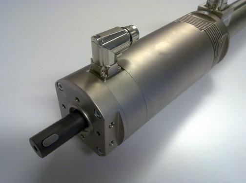
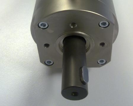
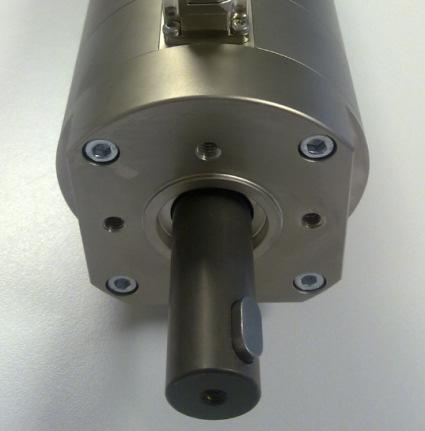
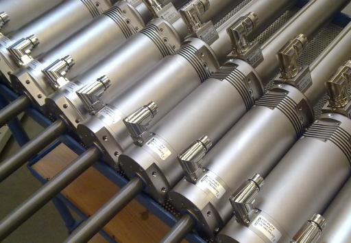
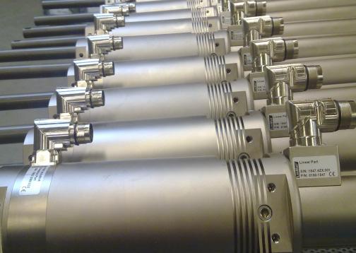
6 Overview LinMot PR01 Linear-Rotary Motors The LinMot PR01 series of Linear-Rotary motors includes various sizes that differ primarily in the maximum torque available from the rotary motor or the linear force available from the linear motor. In addition to the different sizes, variants with axial through-holes (for a pneumatic line or an ejector, for example) and stainless steel models are available. A Linear-Rotary motor fandamentally consists of a linear motor with an attached rotary torque motor. The two motors are electrically independent units and can be controlled completely independently of each other. 1. Rotary Motor 2. Linear Motor 3. Shaft (moves linear and rotating) 4. Slider of the Linear Motor (moves linear) 5. Option: Wiper 6. Option: Heat sinks for Linear Motor 7. Option: MagSpring Multifunction flange 8. Option: MagSpring Mounting Screw / pneumatic supply L version 9. Option: MagSpring - Adapter 10. Option: MagSpring - Slider 11. Option: MagSpring - Stator 12. Option: Fan kit for Rotary Motor 13. Option: Clamp Set for load attachment NTI AG/ LinMot PR_MotorSeries-V2.6e.odt 6/71
7 Part names Linear-Rotary motors are supplied fully assembled. The following list gives information about the individual components used. Variants model 52 PR01-52x40-R/37x120F-HP-C-80 (solid shaft) Part-No: Consisting of: Rotary motor: RS01-52x40-R Part-No: Linear motor: PS01-37x120F-HP-C-80 Part-No: Slider: PL01-20x258/220-HP-PR Part-No: Shaft: RS01k-DA243x12 Part-No: PR01-52x40-R/37x120F-HP-C-80-L (hollow shaft ) Part-No: Consisting of: Rotary motor: RS01-52x40-R Part-No: Linear motor: PS01-37x120F-HP-C-80 Part-No: Slider: PL01-20x258/220-HP-PR-L-G18 Part-No: Shaft: RS01k-DA243x12-L Part-No: PR01-52x60-R/37x120F-HP-C-100 (solid shaft) Part-No: Consisting of: Rotary motor: RS01-52x60-R Part-No: Linear motor: PS01-37x120F-HP-C-100 Part-No: Slider: PL01-20x285/240-HP-PR Part-No: Shaft: RS01k-DA283x12 Part-No: PR01-52x60-R/37x120F-HP-C-100-L (hollow shaft ) Part-No: Consisting of: Rotary motor: RS01-52x60-R Part-No: Linear motor: PS01-37x120F-HP-C-100 Part-No: Slider: PL01-20x285/240-HP-PR-L-G18 Part-No: Shaft: RS01k-DA283x12-L Part-No: PR01-52x60-R/37x120F-HP-C-150 (solid shaft) Art.-Nr.: Consisting of: Drehmotor: RS01-52x60-R Art.-Nr.: Linearmotor: PS01-37x120F-HP-C-150 Art.-Nr.: Läufer: PL01-20x320/240-HP-PR Art.-Nr.: Drehachse: RS01h-DA383x12 Art.-Nr.: (available 1.Q 2014) PR01-52x60-R/37x120F-HP-C-150-L (hollow shaft) Art.-Nr.: Consisting of: Drehmotor: RS01-52x60-R Art.-Nr.: Linearmotor: PS01-37x120F-HP-C-150 Art.-Nr.: Läufer: PL01-20x320/240-HP-PR-L-G18 Art.-Nr.: Drehachse: RS01h-DA383x12-L Art.-Nr.: (available ab 1.Q 2014) NTI AG/ LinMot PR_MotorSeries-V2.6e.odt 7/71
8 Variants model 84 PR01-84x80-C/48x240F-C-100 (solid shaft) Part-No: Consisting of: Rotary Motor: RS01-84x80-C Part-No: Linear Motor: PS01-48x240F-C-100 Part-No: Slider: PL01-28x377/330-PR Part-No: shaft: RS01k-DA345x20 Part-No: PR01-84x80-C/48x240F-C-100-L (hollow shaft) Part-No: Consisting of: Rotary Motor: RS01-84x80-C Part-No: Linear Motor: PS01-48x240F-C-100 Part-No: Slider: PL01-28x377/330-PR-L-G14 Part-No: shaft: RS01k-DA345x20-L Part-No: PR01-84x80-C/48x360F-C-100 (solid shaft) Part-No: Consisting of: Rotary Motor: RS01-84x80-C Part-No: Linear Motor: PS01-48x360F-C-100 Part-No: Slider: PL01-28x500/450-PR Part-No: shaft: RS01k-DA345x20 Part-No: PR01-84x80-C/48x360F-C-100-L (hollow shaft ) Part-No: Consisting of: Rotary Motor: RS01-84x80-C Part-No: Linear Motor: PS01-48x360F-C-100 Part-No: Slider: PL01-28x500/450-PR-L-G14 Part-No: shaft: RS01k-DA345x20-L Part-No: PR01-84x80-C/48x240F-C-300 (solid shaft) Part-No: Consisting of: Rotary Motor: RS01-84x80-C-300 Part-No: Linear Motor: PS01-48x240F-C-300 Part-No: Slider: PL01-28x528/480-PR Part-No: shaft: RS01h-DA692x20 Part-No: NTI AG/ LinMot PR_MotorSeries-V2.6e.odt 8/71
9 Variants model 84 in 'Stainless Steel' PR01-84x80-SSC-C/48x240F-C-150 (solid shaft, Stainless Steel ) Part-No: Consisting of: Rotary Motor: RS01-84x80-SSC-C Part-No: Linear Motor: PS01-48x240F-C-150 Part-No: Slider: PL01-28x377/330-PR Part-No: shaft: RS01k-DA440x20-SSC Part-No: PR01-84x80-SSC-C/48x240F-C-150-L (hollow shaft, Stainless Steel ) Part-No: Consisting of: Rotary Motor: RS01-84x80-SSC-C Part-No: Linear Motor: PS01-48x240F-C-150 Part-No: Slider: PL01-28x377/330-PR-L-G14 Part-No: shaft: RS01k-DA440x20-L-SSC Part-No: PR01-84x80-SSC-C/48x360F-C-150 (solid shaft, Stainless Steel ) Part-No: Consisting of: Rotary Motor: RS01-84x80-SSC-C Part-No: Linear Motor: PS01-48x360F-C-150 Part-No: Slider: PL01-28x500/450-PR Part-No: shaft: RS01h-DA440x20-SSC Part-No: R01-84x80-SSC-C/48x360F-C-150-L (hollow shaft Stainless Steel) Part-No: Consisting of: Rotary Motor: RS01-84x80-SSC-C Part-No: Linear Motor: PS01-48x360F-C-150 Part-No: Slider: PL01-28x500/450-PR-L-G14 Part-No: shaft: RS01h-DA440x20-L-SSC Part-No: NTI AG/ LinMot PR_MotorSeries-V2.6e.odt 9/71
10 Variants model 84 with planetary gear PR01-84x80-C-G/48x240F-C-150-G05 Art.-Nr.: Consisting of: Drehmotor: RS01-84x80-C-G Art.-Nr.: Getriebe: RS01k-EPLFE90-I05 Art.-Nr.: Linearmotor: PS01-48x240F-C-150 Art.-Nr.: Läufer: PL01-28x377/330-PR Art.-Nr.: Drehachse: RS01k-DA345x20 Art.-Nr.: PR01-84x80-C-G/48x240F-C-150-G07 Art.-Nr.: Consisting of: Drehmotor: RS01-84x80-C-G Art.-Nr.: Getriebe: RS01k-EPLFE90-I07 Art.-Nr.: Linearmotor: PS01-48x240F-C-150 Art.-Nr.: Läufer: PL01-28x377/330-PR Art.-Nr.: Drehachse: RS01k-DA345x20 Art.-Nr.: PR01-84x80-C-G/48x240F-C-150-G10 Art.-Nr.: Consisting of: Drehmotor: RS01-84x80-C-G Art.-Nr.: Getriebe: RS01k-EPLFE90-I10 Art.-Nr.: Linearmotor: PS01-48x240F-C-150 Art.-Nr.: Läufer: PL01-28x377/330-PR Art.-Nr.: Drehachse: RS01k-DA345x20 Art.-Nr.: PR01-84x80-C-G/48x360F-C-150-G05 Art.-Nr.: Consisting of: Drehmotor: RS01-84x80-C-G Art.-Nr.: Getriebe: RS01k-EPLFE90-I05 Art.-Nr.: Linearmotor: PS01-48x360F-C-150 Art.-Nr.: Läufer: PL01-28x500/450-PR Art.-Nr.: Drehachse: RS01k-DA345x20 Art.-Nr.: PR01-84x80-C-G/48x360F-C-150-G07 Art.-Nr.: Consisting of: Drehmotor: RS01-84x80-C-G Art.-Nr.: Getriebe: RS01k-EPLFE90-I07 Art.-Nr.: Linearmotor: PS01-48x360F-C-150 Art.-Nr.: Läufer: PL01-28x500/450-PR Art.-Nr.: Drehachse: RS01k-DA345x20 Art.-Nr.: PR01-84x80-C-G/48x360F-C-150-G10 Art.-Nr.: Consisting of: Drehmotor: RS01-84x80-C-G Art.-Nr.: Getriebe: RS01k-EPLFE90-I10 Art.-Nr.: Linearmotor: PS01-48x360F-C-150 Art.-Nr.: Läufer: PL01-28x500/450-PR Art.-Nr.: Drehachse: RS01k-DA345x20 Art.-Nr.: NTI AG/ LinMot PR_MotorSeries-V2.6e.odt 10/71
11 Technical data model 52 Unit PR01-52x40-R/ 37x120F-HP- C-80 (-L) PR01-52x60-R/ 37x120F-HP- C-100 (-L) PR01-52x60-R/ 37x120F-HP- C-150 (-L) Linear Motor* Max Stroke mm Short stroke range mm Peak Force **** N 255 (-L 229) 255 (-L 229) 255 (-L 229) Cont. Force with Fan **** N 92 (-L 82) 92 (-L 82) 92 (-L 82) Cont Force **** N 51 (-L 45) 51 (-L 45) 51 (-L 45) Max Velocity m/s Max Current A Force Constant N/A Repeatability mm +/ / / Phase Resistance (20 C) Ohm Phase Induction mh Linearity % +/ / /- 0.1 Rotary Motor* Peak Torque (stall) (M 0 Max) Nm Continuous Torque (stall) Nm Continuous Torque (stall) with Fan Recommended max revolution (n Max) Nm rpm Max Current** Arms Torque constant Nm/Arms NTI AG / LinMot PR_MotorSeries-V2.6e.odt 11/71
12 Unit PR01-52x40-R/ 37x120F-HP- 80 (-L) PR01-52x60-R/ 37x120F-HP- 100 (-L) PR01-52x60-R/ 37x120F-HP- 150 (-L) Concentricity (max stroke without payload) mm <+/-0.05 <+/-0.05 <+/-0.07 Phase Resistance (20 C) Ohm Induction mh Repeatability +/ (+/-3') +/ (*/-3') +/ (*/-3') Mechanical Dimensions*** Length mm Diameter Linear Motor mm Diameter Rotary Motor mm Fitting Flange (front) mm Mass Total kg Moving mass (linear) kg Moment of inertia (rotation) kgcm Diameter shaft mm 12h9 12h9 12h9 Option hollow shaft ja ja ja***** Diameter hole (-L version) 3 mm Connection (front) M5/ back 1/8 3 mm Connection (front) M5/ back 1/8 3 mm Anschluss vorne M5/ hinten 1/8 Protection Class IP54 IP54 IP54 Specification of products are subject to change without notification * with Drive E1200-UC series ** Attention: LinMot Talk shows peak current -->( Irms:= Ipeak/1.4) ***details see drawings **** hollow shaft versions -L: 10% reduced force (data in bracket) ***** Available 1. Q 2014 NTI AG/ LinMot PR_MotorSeries-V2.6e.odt 12/71
13 Technical data model 84 Unit PR01-84x80-C/ 48x240F- C-100 (-L) PR01-84x80-C/ 48x360F- C-100 (-L) PR01-84x80- SSC-C/ 48x240F-C-150 (-L) PR01-84x80- SSC-C/ 48x360F-C-150 (-L) PR01-84x80-C/ 48x240F-C-300 Linear Motor* Max Stroke mm Short stroke range mm Peak Force**** N 572 (-L 514) 1024 (-L 921) 572 (-L 514) 1024 (-L 921) 572 Cont. Force with Fan**** N 255 (-L 230) 354 (-L 319) 255 (-L 230) 354 (-L 319) 255 Cont Force**** N 145 (-L 130) 203 (-L 182) 145 (-L 130) 203 (-L 182) 145 Max Velocity m/s Max Current A Force Constant N/A Repeatability mm +/ / / / / Phase Resistance (20 C) Ohm Rotary Motor* Phase Induction mh Peak Torque (stall) Linearity % +/ / / / / (M 0 Max) Nm Continuous Torque (stall) Nm Continuous Torque (stall) mit Fan Recommended max revolution (n Max) Nm rpm Max Current** Arms Torque constant Nm/Arms NTI AG / LinMot PR_MotorSeries-V2.6e.odt 13/71
14 Unit PR01-84x80-C/ 48x240F-C-100 (-L) PR01-84x80-C/ 48x360F-C-100 (-L) PR01-84x80- SSC-C/ 48x240F-C-150 (-L) PR01-84x80- SSC-C/ 48x360F-C-150 (-L) PR01-84x80-C/ 48x240F-C-300 Concentricity (max stroke without payload) mm <+/-0.05 <+/-0.05 <+/-0.07 <+/-0.07 <+/-0.3 Phase Resistance (20 C) Ohm Induction mh Repeatability +/ (*/-3') +/ (*/-3') +/ (*/-3') +/ (*/-3') +/ (*/-3') Mechanical Dimensions*** Length mm Diameter Linear Motor mm Diameter Rotary Motor mm Fitting Flange (front) mm Mass Total kg Moving mass (linear) kg Moment of inertia (rotation) kgcm Diameter shaft mm 20h9 20h9 20h9 20h9 20h9 Option hollow shaft in shaft ja Ja ja ja nein Diameter hole (-L version) 4 mm / (Connection ¼ ) 4 mm / (Connection ¼ ) 4 mm / (Connection ¼ ) 4 mm / (Connection ¼ ) Protection Class IP54 IP54 IP54 / IP65 IP54 / IP65 IP54 Specification of products are subject to change without notification * with Drive E1200-UC series ** Attention: LinMot Talk shows peak current -->( Irms:= Ipeak/1.4) *** details see drawings **** hollow shaft versions -L: 10% reduced force (data in bracket) -- NTI AG/ LinMot PR_MotorSeries-V2.6e.odt 14/71
15 Technical data model 84 with planetary gear Unit PR01-84x80-C- G/ 48x240F- C-150-G.. PR01-84x80-C- G/ 48x360F- C-150-G.. Linear Motor* Max Stroke mm Short stroke range mm Peak Force**** N 572 (-L 514) 1024 (-L 921) Cont. Force with Fan**** N 255 (-L 230) 354 (-L 319) Cont Force**** N 145 (-L 130) 203 (-L 182) Max Velocity m/s Max Current A Force Constant N/A Repeatability mm +/ / Phase Resistance (20 C) Ohm Rotary Motor* Phase Induction mh Peak Torque (stall) Linearity % +/ / (M 0 Max) Nm Continuous Torque (stall) Nm Continuous Torque (stall) mit Fan Recommended max revolution (n Max) Nm U/min Max Current** Arms Torque constant Nm/Arms NTI AG / LinMot PR_MotorSeries-V2.6e.odt 15/71
16 Unit PR01-84x80-C- G/ 48x240F-C- 150-G.. PR01-84x80-C- G/ 48x360F-C- 150-G.. Gear ratio i 5/710 5/7/10 Phase Resistance (20 C) Ohm Induction mh Repeatability +/ (*/-3') +/ (*/-3') Mechanical Dimensions*** Length mm Diameter Linear Motor mm Diameter Rotary Motor mm Mass Total kg Moving mass (linear) kg Moment of inertia (rotation) kgcm Option hollow shaft in shaft Not available Not available Protection Class IP54 IP54 Specification of products are subject to change without notification * with Drive E1200-UC series ** Attention: LinMot Talk shows peak current -->( Irms:= Ipeak/1.4) *** details see drawings **** hollow shaft versions -L: 10% reduced force (data in bracket) NTI AG/ LinMot PR_MotorSeries-V2.6e.odt 16/71
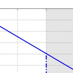
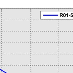
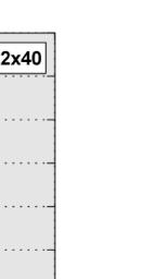
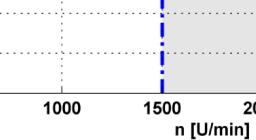

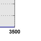
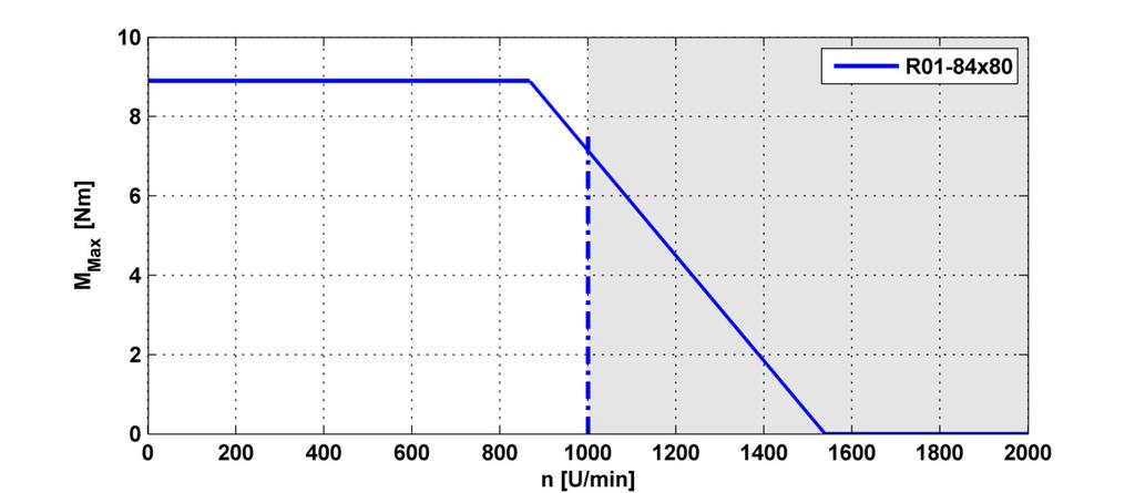
17 Torque-Speed Curve Rotary Motors NTI AG / LinMot PR_MotorSeries-V2.6e.odt 17/71
 is started up first.")
18 Startup The linear motor and rotary motor are electrically independent units. This means that the Linear-Rotary motor can be started up sequentially. It makes no difference which motor (linear or rotary) is started up first. Drive settings The various parameters for the linear motor and the rotary motor are set using the corresponding wizard in the LinMot Talk configuration program. (Contact LinMot Support if you do not see the folder "Motors\LinMot Linear Rotary Motor".) The Linear-Rotary motors are located in the folder "Motors\LinMot Linear Rotary Motors". It makes no difference whether the linear or rotary motor is configured first. NTI AG/ LinMot PR_MotorSeries-V2.6e.odt 18/71


19 Configuration Linear Motor Configuration Rotary Motor NTI AG/ LinMot PR_MotorSeries-V2.6e.odt 19/71

20 Homing the Rotary Motor No homing is necessary, because the rotary motor uses an absolute measurement system (single turn). Homing the Linear Motor If the linear motor is homed to the internal stop of the Linear-Rotary motor, then the maximum homing velocity must be no greater than 0.01 m/s. Example of VAI motion with Rotary Motor The LinMot Talk program uses units on the parameter page the same way they are used to actuate linear motors. In order to control a rotary motor, therefore, a ratio between one motor revolution (360 ) and the linear travel distance must be defined (by default, 1 revolution through 360 corresponds to a linear travel distance of 36 mm). Motor Wizard: Motor Angle to Position Ratio NTI AG/ LinMot PR_MotorSeries-V2.6e.odt 20/71
21 The ratio can be freely defined. Keep in mind that the "position" parameter type is defined as a 32-bit value and the maximum position resolution is 0.1 µm. This means that the maximum stroke is limited to between mm and mm. Position [mm] to revolution = 36 mm (1 == 0.1 mm) Maximum number of revolutions = revolution = 360 mm (1 == 1 mm) Maximum number of revolutions = 1193 The ratio, however, affects not only the positions but also the PID controller. The table below shows an example of this: P [A/mm] 5 1 revolution = 36 mm (1 == 0.1 mm) For a deviation of 1, the drive reacts with 0.5 A 1 revolution = 360 mm (1 == 1 mm) For a deviation of 1, the drive reacts with 5 A This means that if the "Motor Angle to Position Ratio" is changed, the controller parameters must be (manually) adjusted as well. Example of motion using a VAI motion command A VAI Motion Command (motion using the Velocity Acceleration Interpolator) can be started directly via the LinMot Talk program. 1) Definition of the movement: Number of revolutions 25 Acceleration phase 100 [ms] Maximal velocity 1500 [rpm] Delay 50 [ms] 1 Revolution 36 [mm] 2) Converting the rotary parameters into the linear system: Target Position[mm]=Number of revolutions 36[mm]=900[mm] Maximal Velocity[m/ s]=(1500[1/min] 0.036[m])/ 60=0.9[m/ s] Acceleration[m/s 2 ]=Maximal Velocity[m/ s]/0.1[s]=9[m/ s 2 ] Deceleration[m/ s 2 ]=Maximal Velocity[m/s]/0.05[ s]=18[m/ s 2 ] NTI AG/ LinMot PR_MotorSeries-V2.6e.odt 21/71

22 3) Entering the parameters in LinMot-Talk Control Panel Motion Cmd Interface Using the oscilloscope (integrated in LinMot-Talk), the motion can be recorded and the PID control parameters can be adjusted as needed. Picture: LinMot-Talk - Oscilloscope NTI AG/ LinMot PR_MotorSeries-V2.6e.odt 22/71

23 Notes on operating the Linear-Rotary Motor During operation the linear motor must not be allowed to strike the upper or lower internal stops, as this can cause damage to the Linear-Rotary motor. The internal stops can be used for homing purposes, but the homing speed must not exceed the value of 0.01 m/s. The Linear-Rotary motor is designed to execute linear and rotary motions simultaneously. This means that the rotary and linear motions can be executed simultaneously and completely independent of one another. If the application permits, however, the following guidelines should be followed for physical technical reasons: Rotary motions should be performed with the linear axis retracted if possible, as this can reduce vibrations and mechanical loads due to asymmetrical load mass. Execute rotary and linear motions sequentially, which makes the load on the electrical power source more uniform and thus leads to greater energy efficiency. NTI AG/ LinMot PR_MotorSeries-V2.6e.odt 23/71
. The rotary axis is sealed against the stator.")
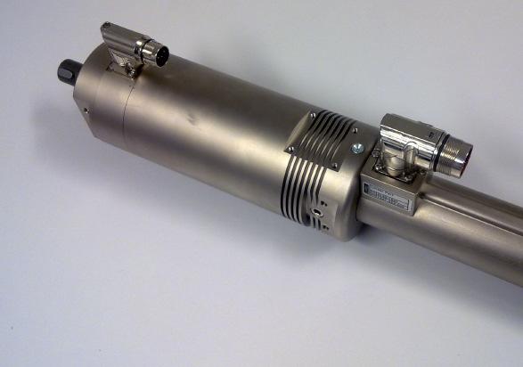
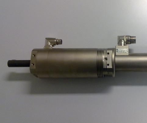
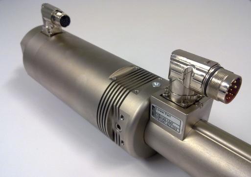
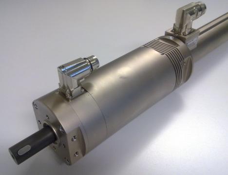
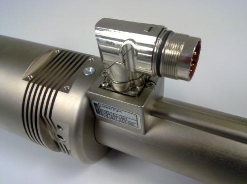
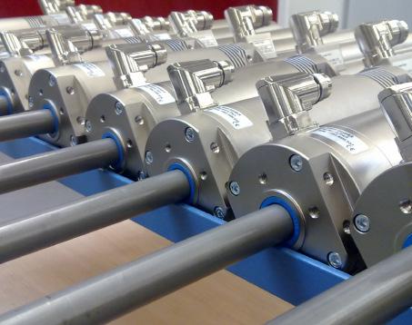
24 Stainless steel variant of the PR01-84x80-SSC series In addition to standard Linear-Rotary Motors, variants made of chromium steel are available in the PR01-84 series. Both the front flange and the rotary axis are made of chromium steel (V4A). The rotary axis is sealed against the stator. For maintenance purposes, the front Part of the flange, where the seals and guides are located, can be removed. The Linear-Rotary motor does not need to be removed from the system in order to remove the flange. Picture: Linear-Rotary Motor PR01-84x80-SSC-C/ 48x240F-C-150 Picture: Front part of the flange, includes sealing and bearings, can be replaced easily. NTI AG/ LinMot PR_MotorSeries-V2.6e.odt 24/71

25 Notes on application of the PR01-84x80-SSC series The design of the machine should consist of a 'normal' and a 'stainless steel' zone. The 'stainless steel zone' can be cleaned accordingly during operation. The two zones are separated by a stainless steel plate. The flange of the Linear-Rotary motor, also made of stainless steel, is inserted through this steel plate. The cylindrical front end of the flange has a groove with an O-ring that acts as a seal between the 'normal' and the stainless steel zones. Picture: O-ring for sealing between 'normal' and 'stainless steel' zone. Notes on cleaning the SSC variants The rotary axis should not be set in motion while the line is being cleaned. It should be either fully extended or fully retracted. The chromium steel zone has IP65 class protection. The seals are made from FKM fluorelastomer and 85 AU polyester-urethane rubber. NTI AG/ LinMot PR_MotorSeries-V2.6e.odt 25/71

26 Example: Linear-Rotary motors on a turntable Picture: Typical arrangement of a system with Linear-Rotary motors and drives on a turntable. The lowest turntable is the divider between the 'stainless steel' and 'normal' zones. The drives for actuating the motors are located above the Linear-Rotary motors. NTI AG/ LinMot PR_MotorSeries-V2.6e.odt 26/71
27 Installing Linear-Rotary Motors The PR01 Linear-Rotary motors have a center fit on the front side so that the rotary axis can be precisely aligned. Due to the narrow construction of the Linear-Rotary motors, it is often not sufficient to mount them by the front bolts alone (due to vibration or lateral loads). An additional support is then necessary. The following sketches show examples of the various possibilities. The chapter on installation drawings contains detailed dimensions. Abstützung über seitliche Fläche am Rotationsmotor Befestigung über seitliche Flächen am Rotationsmotor NTI AG/ LinMot PR_MotorSeries-V2.6e.odt 27/71
28 Drawings of Linear-Rotary motors with accessories Linear-Rotary Motor without accessories Linear-Rotary Motor Motor with whipper on the backsid Linear-Rotary Motor with fan kit for cooling of the Rotary Motor Linear-Rotary Motor Motor with Multifunction flange and pneumatic brake NTI AG/ LinMot PR_MotorSeries-V2.6e.odt 28/71

29 Linear-Rotary Motor with Multifunction flange and MagSpring Linear-Rotary Motor with Multifunction flange, MagSpring mounting an cooling flange CAD-Files CAD files and STEP files can be downloaded from the CAD download area on the webpage at NTI AG/ LinMot PR_MotorSeries-V2.6e.odt 29/71


30 Accessories Heat sinks for linear motors The following heat sinks, in various lengths, help to cool the linear motor. Option heat sink for linear motor PS01-37x120F-HP-C-.. Article Article L [mm] Mass [kg] Part- No PC01-37x68 heat sink Option heat sink for linear motor PS01-48x240F-C-... and PS01-48x360F-C-... Article Article L [mm] Mass [kg] Part- No PC01-48x100 heat sink PC01-48x117 heat sink NTI AG/ LinMot PR_MotorSeries-V2.6e.odt 30/71


31 Mounting and cooling flange for linear motors The following flanges, in various lengths, are used to mount the Linear-Rotary motor as well as cool the linear motor. Option mounting and cooling flange for Linear Motor PS01-37x120F-HP-C-.. Article Article L [mm] A [mm] B [mm] Mass [kg] Part- No PF02-37x100 Flange 37x100 mm PF02-37x140 Flange 37x140 mm Option mounting and cooling flange for Linear Motors PS01-48x240F-C-... PS01-48x360F-C-... Article Article L [mm] B [mm] Mass [kg] Part- No PF01-48x120 Flange 48x120 mm PF01-48x226 Flange 48x226 mm NTI AG/ LinMot PR_MotorSeries-V2.6e.odt 31/71


32 Fan kits Fan kits are available for both the rotary motor and the linear motor. In general, forced ventilation allows the continuous torque or force to be increased (see design program). Fan kits for Linear Motor Option: Fan for Linear Motor PS01-37x120F-HP-C-.. Connection: 24VDC / 120mA Article fan for Part-No HV01-37/48* Fan Kit for H01-37, B01-37 and PF * order separate mounting and cooling Flange PF02-37x100 or PF02-37x140 Option: Fan for Linear Motor PS01-48x240F-C-.. / PS01-48x360F-C-... Connection: 24VDC / 120 ma Article fan for Part-No HV01-37/48* Fan Kit for H01-48, B01-48 and PF * order separate mounting and cooling Flange PF01-48x120 or PF01-48x226 NTI AG/ LinMot PR_MotorSeries-V2.6e.odt 32/71


33 Fan kit for Rotary Motors Option: fan for Rotary Motor model 52 Connection: red= 24Vdc blue or black=gnd Article fan for Mass Part-No RS01-VA52-Kit Rotary Motor RS kg Option: fan for Rotary Motor model 84 Connection: red= 24Vdc blue or black=gnd Article fan for Mass Part-No RS01-VA84-Kit Rotary Motor RS kg NTI AG/ LinMot PR_MotorSeries-V2.6e.odt 33/71
34 Wipers The rotary axis is protected against dirt and loss of grease by a wiper on the front side. The back side of the linear motor slider should also be protected by means of a wiper. The options 'wiper' and 'multifunctional flange' are available for this. A L D Article Part- No. D L A Mass Wipers for model 52 45mm 32mm 12mm PS01-37x120F-HP-C-.. PA01-37/20-F kg (1.77in) (1.26in) (0.47in) Wipers for model 84 PS01-48x240F-C-... PS01-48x360F-C-... PA01-48/28-F mm (2.28in) 32mm (1.26in) 14mm (0.55in) 0.056kg NTI AG/ LinMot PR_MotorSeries-V2.6e.odt 34/71


35 Multifunction flange and MagSpring The multifunctional flange can perform one or more of the following functions: - Wiper for the linear motor slider - Mounting a MagSpring spring for load compensation - Mounting a pneumatic brake - Mounting element for the Linear-Rotary motor Effective force of the MagSpring Depending on the orientation of the MagSpring slider, the effect of the force can be modified. This means that the MagSpring pulls the rotary axis of the Linear-Rotary motor inward, or pushes it outward. Top: 'Pushing' MagSpring Bottom: 'Pulling' MagSpring NTI AG/ LinMot PR_MotorSeries-V2.6e.odt 35/71
36 Article Part.-Nr for model 52 1 Multifunction flange MF01-PR01-52x Wiper (delivered with Pos 1) PAW01-20 Part.-No MagSpring Stator 22 N force MS01-20x140 Part.-No N / 60 N force MS01-37x155 Part.-No MagSpring Slider 22 N force ML01-12x335/ Part.-No N force ML01-12x350/ Part.-No N force: ML01-12x335/ Part.-No MagSpring adapter MA01-PR01-52x40-37 Part.-No Spacer sleeve MA01-PR01-Huelse4,9 Part.-No (delivered with Pos 5) 7 Socket screw M5x14 / ISO4762 (delivered with Pos 5) 8 Socket screw or pneumatic fitting M8x18 / DIN 7984 (delivered with Pos 5) 9 Socket screw M5x30 / ISO4762 (delivered with Pos 1) 10 Set screw (with cup point) M5x6 / ISO 4029 (delivered with Pos 1) Article Part.-Nr for model 84 MF01-PR01-70x (delivered with Pos 1) PAW01-28 Part.-No MS01-37x155 Part.-No N force ML01-12x350/ Part.-No MA01-PR01-70x40-37 Part.-No MA01-PR01-Huelse4,9 Part.-No (delivered with Pos 5) M5x14 / ISO4762 (delivered with Pos 5) M10x20 /DIN 7984 (delivered with Pos 5) M5x35 / ISO4762 (delivered with Pos 1) M5x12 / ISO 4029 (delivered with Pos 1) Article Part.-Nr for model 84 -L (version with hollow shaft) MF01-PR01-70x (delivered with Pos 1) PAW01-28 Part.-No MS01-37x155 Part.-No N force ML01-12x350/ Part.-No MA01-PR01-70x40-37-L Part.-No MA01-PR01-Huelse4,9 Part.-No (delivered with Pos 5) M5x14 / ISO4762 (delivered with Pos 5) 10mm / ½ (delivered with Pos 5) M5x35 / ISO4762 (delivered with Pos 1) M5x12 / ISO 4029 (delivered with Pos 1) NTI AG/ LinMot PR_MotorSeries-V2.6e.odt 36/71

37 Multifunction flange Material: Al anodized Article Part- No. L B H Mass Multifunction flange for model 52 and MagSpring MS Multifunction flange for model 52 and MagSpring MS Multifunction flange for model 84 and MagSpring MS MF01-PR01-52x mm 40 mm 50 mm 0.33 kg MF01-PR01-52x mm 40 mm 50 mm 0.31 kg MF01-PR01-70x mm 40 mm 60 mm 0.39 kg NTI AG/ LinMot PR_MotorSeries-V2.6e.odt 37/71
 Adapter for model 84-L (version with hollow shaft)) MA01-PR01-70x40-37 0250-0120 65 mm 22 mm 10 mm 0.")
38 Adapter for mounting of MagSpring-Slider. Material: Al anodized Article Part- No. L B H Mass Adapter for model 52 MA01-PR01-52x ,5 mm 30 mm 10 mm kg Adapter for model 84 (version with solid shaft) Adapter for model 84-L (version with hollow shaft)) MA01-PR01-70x mm 22 mm 10 mm kg MA01-PR01-70x40-37-L mm 22 mm 10 mm kg NTI AG/ LinMot PR_MotorSeries-V2.6e.odt 38/71
 model 52 22 N MS01-20x140 0250-2201 140 mm 20 mm 0.18 kg model 52 40N / 60 N MS01-37x155 0250-2204 155 mm 37 mm 0.88 kg model 84 60 N MS01-37x155 0250-2204 155 mm 37 mm 0.")
39 Magnetic spring MagSpring Dimension MagSpring Stator MS01-20x140 Dimension MagSpring Stator MS01-37x155 MagSpring Stator Force (depending Article Part- No. L D Mass on slider) model N MS01-20x mm 20 mm 0.18 kg model 52 40N / 60 N MS01-37x mm 37 mm 0.88 kg model N MS01-37x mm 37 mm 0.88 kg MagSpring Slider Force Article Part- No. L D Mass model N ML01-12x350/ mm 12 mm kg model N ML01-12x350/ mm 12 mm kg model N ML01-12x350/ mm 12 mm kg model N ML01-12x350/ mm 12mm kg Example: Linear-Rotary Motor model 52 with MagSpring of force 40N: Stator: MS01-37x155 Slider: ML01-12x350/ Linear-Rotary Motor model 52 with MagSpring of force 60N: Stator: MS01-37x155 Slider: ML01-12x350/ NTI AG/ LinMot PR_MotorSeries-V2.6e.odt 39/71

40 Load attachment Because both a rotary and a linear motion are performed, the type of attachment must be selected such that it can support both torques and longitudinal forces. Clamp sets that enable fast, easy mounting of the load Mass are available as accessories. They provide a force-fit connection that is created by two conical rings. This completely eliminates the need for inserting lugs or producing grooves. Technical data RS01-SS12x22 : Tmax: 20Nm Fmax: 3kN Tolerance for fit D: 22H9 mm RS01-SS20x38: Tmax: 160Nm Fmax: 15kN Tolerance for fit D: 38H9 mm Clamp set for model 52 Clamp set for model 84 Article Part- No. d D L Lges Mass RS01-SS12x mm 22 mm 13 mm 15.5 mm 22g RS01-SS20x mm 38 mm 21 mm 26 mm 100g NTI AG/ LinMot PR_MotorSeries-V2.6e.odt 40/71

41 Connector assignment Connector assignment Linear Motors Stecker Typ C-Connector Pin Phase 1+ A Phase 1- B Phase 2+ C Phase 2- D +5V E GROand* F Sensor Sinus G Sensor Cosinus H Temp. Sensor L Shield* Casing Connector assignment Rotary Motors Stecker Typ C oder R-Connector Pin Phase A 1 Phase B 2 Phase C 3 NC 4 +5V A GROand* B Sensor Sinus C Sensor Cosinus D Temp. Sensor E Shield* Casing Extension cables are double shielded. The two shields of the extension cables must not be connected together: The inner shield of the extension cables is used as GROand and must be connected to GROand*, only the outer shield must be connected to SHIELD* of the connectors. Caution: Do not connect or disconnect motor when there is power on the controller. Double-check each connection! Wrong connections can destroy controller and stator! NTI AG/ LinMot PR_MotorSeries-V2.6e.odt 41/71
42 Drawings Drawing PR01-52x40-R/37x120F-HP-C-80 NTI AG/ LinMot PR_MotorSeries-V2.6e.odt 42/71
43 Stroke range PR01-52x40-R/37x120F-HP-C-80 NTI AG/ LinMot PR_MotorSeries-V2.6e.odt 43/71
44 Drawing PR01-52x60-R/37x120F-HP-C-100 NTI AG/ LinMot PR_MotorSeries-V2.6e.odt 44/71
45 Stroke range PR01-52x60-R/37x120F-HP-C NTI AG/ LinMot PR_MotorSeries-V2.6e.odt 45/71
46 Drawing PR01-52x60-R/37x120F-HP-C-100 with Flange PF02-37x100 NTI AG/ LinMot PR_MotorSeries-V2.6e.odt 46/71
47 Drawing PR01-52x60-R/37x120F-HP-C-100 with MagSpring NTI AG/ LinMot PR_MotorSeries-V2.6e.odt 47/71
48 Drawing PR01-52x60-R/37x120F-HP-C-100 Flange/MagSpring/Fan NTI AG/ LinMot PR_MotorSeries-V2.6e.odt 48/71
49 Drawing PR01-52x60-R/37x120F-HP-C-150 NTI AG/ LinMot PR_MotorSeries-V2.6e.odt 49/71
50 Stroke range PR01-52x60-R/37x120F-HP-C-150 NTI AG/ LinMot PR_MotorSeries-V2.6e.odt 50/71
51 Drawing PR01-84x80-C/48x240F-C-100 NTI AG/ LinMot PR_MotorSeries-V2.6e.odt 51/71
52 Stroke range PR01-84x80-C/48x240F-C-100 NTI AG/ LinMot PR_MotorSeries-V2.6e.odt 52/71
53 Drawing PR01-84x80-C/48x240F-C-100 with Flange PF01-48x226 NTI AG/ LinMot PR_MotorSeries-V2.6e.odt 53/71
54 Drawing PR01-84x80-C/48x240F-C-100 Multifunction-Flange and MagSpring NTI AG/ LinMot PR_MotorSeries-V2.6e.odt 54/71
55 Drawing PR01-84x80-C/48x240F-C-100 with Flange and MagSpring NTI AG/ LinMot PR_MotorSeries-V2.6e.odt 55/71
56 Drawing PR01-84x80-C/48x360F-C-100 NTI AG/ LinMot PR_MotorSeries-V2.6e.odt 56/71
57 Stroke range PR01-84x80-C/48x360F-C-100 NTI AG/ LinMot PR_MotorSeries-V2.6e.odt 57/71
58 Drawing PR01-84x80-SSC-C/48x240F-C-150 NTI AG/ LinMot PR_MotorSeries-V2.6e.odt 58/71
59 Stroke range PR01-84x80-SSC-C/48x240F-C-150 NTI AG/ LinMot PR_MotorSeries-V2.6e.odt 59/71
60 Drawing PR01-84x80-SSC-C/48x360F-C-150 NTI AG/ LinMot PR_MotorSeries-V2.6e.odt 60/71
61 Stroke range PR01-84x80-SSC-C/48x360F-C-150 NTI AG/ LinMot PR_MotorSeries-V2.6e.odt 61/71
62 Drawing PR01-84x80-C/48x240F-C-300 NTI AG/ LinMot PR_MotorSeries-V2.6e.odt 62/71
63 Stroke range PR01-84x80-C/48x240F-C-300 NTI AG/ LinMot PR_MotorSeries-V2.6e.odt 63/71

64 Drawing PR01-84x80-C-G/48x240F-C-150-G.. NTI AG/ LinMot PR_MotorSeries-V2.6e.odt 64/71
65 Stroke Range PR01-84x80-C-G/48x240F-C-150-G.. NTI AG/ LinMot PR_MotorSeries-V2.6e.odt 65/71
66 Maintenance of LinMot Linear-Rotary Motors The maintenance schedule below is based on a 5-day week with 8 working hours daily. Central European industrial operating conditions are assumed. Where conditions differ, as with severe and permanent fouling, direct sunshine, operation out in the open etc., the maintenance intervals must be shortened till empirical values for the particular application are obtained. Accordingly a distinction is drawn between the maintenance schedules for standard applications and first applications or arduous conditions. Maintenance schedule for standard applications Less than 120 strokes/min strokes/min over 360 strokes/min Commissioning Inspection & lubrication Inspection & lubrication Inspection & lubrication every 3 months -- Inspection Inspection & lubrication every 6 months Inspection Inspection & lubrication Inspection & lubrication Maintenance schedule for first applications / arduous Less than 120 strokes/min strokes/min over 360 strokes/min Commissioning Inspection & lubrication Inspection & lubrication Inspection & lubrication after the first 8 hours Inspection Inspection Inspection after first week Inspection Inspection Inspection every 3 months Inspection Inspection Inspection & lubrication every 6 months Inspection & lubrication Inspection & lubrication Inspection & lubrication Inspection The following must be checked when inspecting the drives: Is the slider lubricated completely. Is the lubricant not decomposed? Can the slider be moved easily? Lubricating instructions The lubricant reduces the friction between the chromium-nickel steel surface of the slider and the plastic plain bearing. In addition it prevents (fretting) corrosion. The lubricant employed must not attack the material of the plain bearing and must be temperature resistant up to 150ºC. Important also is that it should retain low viscosity at low temperatures and not evaporate. The following lubricant is recommended: LinMot Lubricant LU02 Art. No (8g) LinMot Lubricant LU02 Art. No (50g) LinMot Lubricant LU02 Art. No (1000g) LinMot LU02 Lubricant corresponds to KLÜBERSYNTH UH which was developed for the food processing industry. Storage / transport Sliders are to be stored and transported only in the plastic containers (with cardboard inlay) provided for this, or already fitted in LinMot motors and secured. Maximum storage temperature: 70 C NTI AG/ LinMot PR_MotorSeries-V2.6e.odt 66/71
67 Trouble Shooting Trouble Shooting of Linear Motors The following tables show the resistive value between the different connector pins for each stator type. If the value is not in a range of +/- 10% the stator may be damaged (temperature of the stator for all measurements: 20 C). PS01 37x120F-HP-C-80 Phase1+ / Phase1- Pin A / Pin B 2.6Ω Phase2+ / Phase2- Pin C / Pin D 2.6 Ω 5V / GND Pin E / Pin F 155 Ω Sensor Sinus / GND Pin G / Pin F 33 kω Sensor Cosine / GND Pin H / Pin F 33 kω Temp. Sensor / GND Pin L / Pin F 10kΩ Phase / GND Pin A,B,C,D / Pin F >20 MΩ All Pin / Shield Pin A-L / Housing >20 MΩ PS01 37x120F-HP-C-100 Phase1+ / Phase1- Pin A / Pin B 2.6Ω Phase2+ / Phase2- Pin C / Pin D 2.6 Ω 5V / GND Pin E / Pin F 155 Ω Sensor Sinus / GND Pin G / Pin F 33 kω Sensor Cosine / GND Pin H / Pin F 33 kω Temp. Sensor / GND Pin L / Pin F 10kΩ Phase / GND Pin A,B,C,D / Pin F >20 MΩ All Pin / Shield Pin A-L / Housing >20 MΩ PS01 48x240F-C-100 (-150, -300) Phase1+ / Phase1- Pin A / Pin B 1.1 Ω Phase2+ / Phase2- Pin C / Pin D 1.1 Ω 5V / GND Pin E / Pin F 155 Ω Sensor Sin / GND Pin G / Pin F 33 kω Sensor Cos / GND Pin H / Pin F 33 kω Temp. Sensor / GND Pin L / Pin F 10 kω Phase / GND Pin A,B,C,D / Pin F >20 MΩ Alle Pins / Shield Pin A-L / Gehäuse >20 MΩ PS01 48x360F-C-100 (-150) Phase1+ / Phase1- Pin A / Pin B 1.5 Ω Phase2+ / Phase2- Pin C / Pin D 1.5 Ω 5V / GND Pin E / Pin F 155 Ω Sensor Sin / GND Pin G / Pin F 33 kω Sensor Cos / GND Pin H / Pin F 33 kω Temp. Sensor / GND Pin L / Pin F 10 kω Phase / GND Pin A,B,C,D / Pin F >20 MΩ Alle Pins / Shield Pin A-L / Gehäuse >20 MΩ NTI AG/ LinMot PR_MotorSeries-V2.6e.odt 67/71
68 Trouble Shooting of Rotary Motors The following tables show the resistive value between the different connector pins for each stator type. If the value is not in a range of +/- 10% the stator may be damaged (temperature of the stator for all measurements: 20 C). RS01-52x40-R Phase A / Phase B Pin 1 / Pin 2 7.1Ω Phase A / Phase C Pin 3 / Pin Ω 5V / GND Pin A / Pin B 155 Ω Sensor Sinus / GND Pin C / Pin B 33 kω Sensor Cosine / GND Pin D / Pin B 33 kω Temp. Sensor / GND Pin E / Pin B 10kΩ Phase / GND Pin 1,2,3,4 / Pin B >20 MΩ All Pin / Shield Pin 1-E / Housing >20 MΩ RS01-52x60-R Phase A / Phase B Pin 1 / Pin 2 3Ω Phase A / Phase C Pin 3 / Pin 4 3 Ω 5V / GND Pin A / Pin B 155 Ω Sensor Sinus / GND Pin C / Pin B 33 kω Sensor Cosine / GND Pin D / Pin B 33 kω Temp. Sensor / GND Pin E / Pin B 10kΩ Phase / GND Pin 1,2,3,4 / Pin B >20 MΩ All Pin / Shield Pin 1-E / Housing >20 MΩ RS01-52x60-R (Delivery until June 2011) Phase A / Phase B Pin 1 / Pin Ω Phase A / Phase C Pin 3 / Pin Ω 5V / GND Pin A / Pin B 155 Ω Sensor Sinus / GND Pin C / Pin B 33 kω Sensor Cosine / GND Pin D / Pin B 33 kω Temp. Sensor / GND Pin E / Pin B 10kΩ Phase / GND Pin 1,2,3,4 / Pin B >20 MΩ All Pin / Shield Pin 1-E / Housing >20 MΩ RS01-84x80-C / RS01-84x80-SSC-C / RS01-84x80-C-300 Phase A / Phase B Pin A / Pin B 1.1Ω Phase A / Phase C Pin C / Pin D 1.1 Ω 5V / GND Pin E / Pin F 155 Ω Sensor Sinus / GND Pin G / Pin F 33 kω Sensor Cosine / GND Pin H / Pin F 33 kω Temp. Sensor / GND Pin L / Pin F 10kΩ Phase / GND Pin A,B,C,D / Pin F >20 MΩ All Pin / Shield Pin A-L / Housing >20 MΩ NTI AG/ LinMot PR_MotorSeries-V2.6e.odt 68/71
69 Caution: Handling Instructions for Sliders LinMot Slider LinMot Linear Motor sliders must be handled with care especially if not assembled within the stator! Damaging or warping of the slider can result in shortened life and/or failure of the motor. The slider is essentially a high-precision machine component consisting of neodymium magnets and plastic materials assembled in a thin steel tube. Do not use sliders who are already damaged on the surface (scratches, deformation, etc.). This can provide a further damage of the stator! Keep slider away from unshielded flame or heat. Temperature of more than 120 C will cause demagnetization. Magnetism LinMot sliders contain neodymium magnets which may disturb or damage magnetic data carriers and delicate electronic equipment merely by coming close to them. Examples for such equipment are: television and computer monitors, credit cards and EC-cards, computers, floppy discs and other data storage medium, video tapes, mechanical watches, hearing devices and loudspeaker. Heart pacemakers can be disturbed by strong magnets. Keep a minimum distance of 1m. Crushes When handling sliders be aware that, due the strong magnetic attraction, serious injury from fingers being pinched between the slider and nearby steel parts is a very real possibility if caution is not exercised. No modification of sliders provided by customers is allowed! Do not modify the slider in any way. Any modification could destroy the included magnets and magnet dust can be build. Magnet dust is easily inflammable! NdFeB-Magnets are not made of steel. These magnets are sintered and due to that highly breakable. NTI AG/ LinMot PR_MotorSeries-V2.6e.odt 69/71
70 Declaration of Conformity CE-Marking Manufacturer: NTI AG LinMot Haerdlistrasse Spreitenbach Switzerland Tel.: +41 (0) Fax: +41 (0) Products: LinMot Servo Motors Type Part.-No. Type Part.-No. RS01-52x40-R PS01-37x120F-HP-C RS01-52x60-R PS01-37x120F-HP-C RS01-52x60-R PS01-37x120F-HP-C RS01-84x80-R/-C PS01-48x240F-C RS01-84x80-SSC-C PS01-48x360F-C RS01-84x80-C PS01-48x240F-C PS01-48x360F-C PS01-48x240F-C The product must be mounted and used in strict accordance with the installation instruction contained within the User s Manual, a copy of which may be obtained from NTI AG. I declare that as the authorized representative, the above information in relation to the supply/manufacture of this product is in conformity with the stated standards and other related documents in compliance with the protection requirements of the EMC Directive (89/336/EEC) and is marked in accordance with the CE Marking Directive (93/68/EEC). Standards Complied with: Conducted EMI EN Class A EN Electromagnetic EN kv / 8kV Suspectibility EMC EN kv / 2kV EN EN V/m EN V ENV V/m Company NTI AG Spreitenbach, July Dr.-Ing. Ronald Rohner / CEO NTI AG NTI AG/ LinMot PR_MotorSeries-V2.6e.odt 70/71
71 Contact address: NTI AG LinMot Tel. +41 (0) Haerdlistr. 15 Fax. +41 (0) CH-8957 Spreitenbach Switzerland Web: LinMot Inc. 204 E Morrissey Dr. Phone: Elkhorn Fax: WI sales@linmot-usa.com USA Web: Liability NTI AG / LinMot (LinMot) is not responsible for any damages caused by improper use, application, or handling of LinMot manufactured or supplied materials and is not responsible for any consequential damages of any sort relating to the use of LinMot products. LinMot's warranty is limited to repair or replacement as stated in our standard warranty policy as described in our "terms and conditions" previously supplied to the purchaser of our equipment (please request copy of same if not otherwise available). Product warranties are void if LinMot products are used with stators, sliders, or controllers not manufactured by LinMot unless such use was specifically approved by LinMot. A copy of this notice must be attached to each motor and/or machine that the purchaser provides to others. LinMot, LinRot and MagSpring are registered trademarks of NTI AG Specification of products are subject to change without notification Edition: NTI AG/ LinMot PR_MotorSeries-V2.6e.odt 71/71
LinMot Linear-Rotary Motors Version 2.96e
 LinMot Linear-Rotary Motors Version 2.96e NTI AG / LinMot www.linmot.com 0185-0015-E_2V96_IG_Linear_Rotary_Motors_PR01.odt 1/84 CAUTION LINMOT SLIDERS CONTAIN NEODYMIUM MAGNETS WHICH MAY DISTURB OR DAMAGE
LinMot Linear-Rotary Motors Version 2.94e
 LinMot Linear-Rotary Motors Version 2.94e NTI AG / LinMot 1/79 CAUTION LINMOT SLIDERS CONTAIN NEODYMIUM MAGNETS WHICH MAY DISTURB OR DAMAGE MAGNETIC DATA CARRIERS AND DELICATE ELECTRONIC EQUIPMENT MERELY
LinMot Linear-Rotary Motors Version 2.96e
 LinMot Linear-Rotary Motors Version 2.96e 1/84 CAUTION LINMOT SLIDERS CONTAIN NEODYMIUM MAGNETS WHICH MAY DISTURB OR DAMAGE MAGNETIC DATA CARRIERS AND DELICATE ELECTRONIC EQUIPMENT MERELY BY COMING CLOSE
LinMot F01-37S Guide. Version 1.59e. NTI AG / E_1V59_IG_Linear_Guides_F01-37.odt 1/40
 LinMot F01-37S Guide Version 1.59e NTI AG / www.linmot.com 0185-0026-E_1V59_IG_Linear_Guides_F01-37.odt 1/40 CAUTION LINMOT SLIDERS CONTAIN NEODYMIUM MAGNETS WHICH MAY DISTURB OR DAMAGE MAGNETIC DATA CARRIERS
Version 1.67e E_1V67_IG_Linear_Guides_F01.odt 1/61
 LinMot F01-37S and F01-48 Guides Version 1.67e www.linmot-usa.com 0185-0026-E_1V67_IG_Linear_Guides_F01.odt 1/61 CAUTION LINMOT SLIDERS CONTAIN NEODYMIUM MAGNETS WHICH MAY DISTURB OR DAMAGE MAGNETIC DATA
Linear Rotary Motors. Linear-Rotary Motors. The linear motor technology for industrial applications. Linear and rotary direct drive
 Linear Rotary Motors Linear-Rotary Motors Linear and rotary direct drive Independent linear and rotary motion Synchronised linear and rotary motion Programmable press force up to 1 24N Programmable tightening
Assembly Instructions for H- and B Guide with Linear Motor
 Assembly Instructions for H- and B Guide with Linear Motor Version 1.2 H-Guide Series: H01-23x86/... H01-23x166/... H01-37x166/.. H01-37x286/... H01-48x250/... B01-48x250/... B-Guide Series B01-37x166/..
MagSpring Magnetic Springs
 MagSpring Magnetic Springs MagSpring, unlike mechanical springs, deliver a constant force over their entire working rang MagSpring, consists of only two components: a stator and a slider MagSprings are
Installation Guide Linear Guides H01-23 / 37 / 48
 H01-23 / 37 / 48 NTI AG / LinMot Dok-Nr. 0185-0083-E_1V1_IG_Linear_Guides_H01 Content 1 General information... 4 Introduction... 4 Explanation of symbols... 4 Qualified personnel... 4 Liability... 4 Copyright...
Linear Motor Series P10-70
 Linear Motor Series P10- Peak force up to 2 500N Velocity up to 5m/s Acceleration up to 100g Free positioning Long life: Linear direct drive The linear motor technology for industrial applications LinMot
Linear Motors & Servo Drives 3x400VAC. Linear Motor Series P The linear motor technology for industrial applications. Peak force up to 2 500N
 Linear Motors & Servo Drives 3x400VAC Linear Motor Series P10- Peak force up to 2 500N Velocity up to 5m/s Acceleration up to 100g Free positioning Long life: Linear direct drive The linear motor technology
The linear motor technology for industrial applications
 Industrial Linear Motors Purely electrical drive system Freely positionable along the entire stroke For precise and dynamic positioning tasks Direct drive technology provides longer life Clean room certification
LinMot Industrial Linear Motors LinMot linear motors are direct electromagnetic drives. The linear motion is generated without wear, with no intermedi
 Industrial Linear Motors Purely electrical drive system Freely positionable along the entire stroke For precise and dynamic positioning tasks Linear motor technology provides longer life IP67 protection
P02-23Sx80F-HP-K. The linear motor technology for industrial applications. Tel: 00352/ Fax: 00352/
 P2-23Sx8F-HP-K Import Belgium & Luxembourg Profilex s.a. S 4A, Z.I. In den Allern L-9911 Troisvierges Tel: 352/99 89 6 Fax: 352/26 95 73 73 www.profilex-systems.com profilex@pt.lu The linear motor technology
Linear Guide Units H01
 inear Guide Units 01 ccurate guidance for unsupported loads Protection against external forces ow friction ball bearing version Plain bearing version for rough environment inmot the Technology for Industrial
Courtesy of CMA/Flodyne/Hydradyne Motion Control Hydraulic Pneumatic Electrical Mechanical (800)
") P01 LinMot P is a family of linear direct drives for highly dynamic motions. The motor is made up of just two parts: the slider and the stator. The two parts are not connected by brushes or cables. The
P01 LinMot P is a family of linear direct drives for highly dynamic motions. The motor is made up of just two parts: the slider and the stator. The two parts are not connected by brushes or cables. The
Installation Guide Linear Motors P01 Stainless Steel
 P01 Stainless Steel NTI AG / LinMot Dok-Nr. 0185-0014-E_2V1_IG_Linearmotoren_P01-SSC Content 1 General information... 4 1.1 Introduction... 4 1.2 Explanation of symbols... 4 1.3 Qualified personnel...
Installation Guide for partly completed maschines according to maschinery directive 2006/42/EG app. VI. Maintenance Instructions
 eg_montageanleitung_einbauerklaerung_ha01_en.doc Rev.: 05.12.2017 Subject to change! Installation Guide for partly completed maschines according to maschinery directive 2006/42/EG app. VI Maintenance Instructions
Industrial Linear Motor Systems
 Industrial Linear Motor Systems electric linear direct drive system precision & high dynamics for positioning tasks freely positionable along the entire stroke long operational life IP protection class
MagSpring. Courtesy of Steven Engineering, Inc. - (800)
") 468 www.linmot.com M01-20 472 M01-37 474 Accessories 476 www..com 469 products can best be described as "magnetic springs." The term "spring", however, is to be understood to mean that components generate
468 www.linmot.com M01-20 472 M01-37 474 Accessories 476 www..com 469 products can best be described as "magnetic springs." The term "spring", however, is to be understood to mean that components generate
Industrial Linear Motors
 Industrial Linear Motors Smart solutions are driven by PRODUCT OVERVIEW www.linmot.com Precision and dynamics In the products and in the everyday life of NTI AG, these values are inseparable. NTI AG NTI
Directional servo-valve of 4-way design
 Courtesy of CM/Flodyne/Hydradyne Motion Control Hydraulic Pneumatic Electrical Mechanical (0) 426-54 www.cmafh.com Directional servo-valve of 4-way design Type 4WSE3E 32 Size 32 Component series 5X Maximum
V SWISS MADE LINEAR TECHNOLOGY
 Compact units Excerpt from main catalogue SWISS MADE LINEAR TECHNOLOGY V 11-15 Line Tech compact units Table of contents Product overview 106 107 Design fundamentals / Lubrication / Maintenance 108 Profile
Flexible. Fast. Reliable. ELM Compact Linear Module
 ELM Flexible. Fast. Reliable. ELM Compact Linear Module With linear direct drive and profiled rail guide with integrated measuring system for position detection and temperature monitoring. Field of Application
Operating Instructions. Angle Seat Control Valve. Type 7020
 Operating Instructions Angle Seat Control Valve Type 7020 With: Digital Positioner Type 8048 Electro-pneumatic Positioner Type 8047 Pneumatic Positioner Type 8047 Version: 02/2006 Manual-7020e.doc Art.-No:
1. Product overview Basic-Line-Module AXN Product description Basic-Line-Module AXN 4-5. Guide system Roller guide 6 Drive system Gear belt 7
 Directory Page 1. Product overview Basic-Line-Module AXN 3 2. Product description Basic-Line-Module AXN 4-5 Guide system Roller guide 6 Drive system Gear belt 7 3. Basic-Line-Modul AXN 45-Z 8-9 AXN 65-Z
Industrial Linear Motors
 Industrial Linear Motors Smart solutions are driven by PRODUCT OVERVIEW www.linmot.com Precision and dynamics In the products and in the everyday life of NTI AG, these values are inseparable. NTI AG NTI
Digital Pressure Regulator Sentronic PLUS Series 614
 Digital Pressure Regulator Sentronic PLUS Series 14 Installation manual IM149-/R01 CONTENTS 1. Description... 1.1 Catalogue number... 1. Operating elements...4 1. Operating modes...4. Electrical connection...5.
Industrial Linear Motors
 Industrial Linear Motors Smart solutions are driven by PRODUCT OVERVIEW www.linmot.com Precision and dynamics In the products and in the everyday life of NTI AG, these values are inseparable. NTI AG NTI
* _0916* Drive Technology \ Drive Automation \ System Integration \ Services. Revision. Synchronous Linear Motors SL2
 Drive Technology \ Drive Automation \ System Integration \ Services *23059311_0916* Revision Synchronous Linear Motors SL2 Edition 09/2016 23059311/EN SEW-EURODRIVE Driving the world Table of contents
Courtesy of Steven Engineering, Inc - (800) PATENTED
 PATENTED") PRECISION RING DRIVE SYSTEMS Based on Nexen s innovative Roller Pinion technology, Nexen Ring Drive Systems come complete with a precision grade, high capacity bearing and drive mechanism in a rigid housing.
PRECISION RING DRIVE SYSTEMS Based on Nexen s innovative Roller Pinion technology, Nexen Ring Drive Systems come complete with a precision grade, high capacity bearing and drive mechanism in a rigid housing.
Compact. Fast. Productive. DRL Lift/Swivel Unit
 DRL Compact. Fast. Productive. DRL Lift/Swivel Unit Compact lift/swivel unit consisting of a strong short-stroke cylinder and a rack pinion swivel drive. Field of Application For use in clean and slightly
K Series Kit Motor Reliable and Compact Approach: Build your own high-performance motor
 Frameless K Series Kit Overview K Series Kit Motor Reliable and Compact Approach: Build your own high-performance motor Direct drive motion construction gives equipment designers the advantages of lower
8710 EN. Potentiometric Displacement Sensors. Models 8710, 8711
 Potentiometric Displacement Sensors Models 8710, 8711 Code: Delivery: Warranty: 8710 EN ex stock 24 months Model 8711 Model 8710 Application Displacement sensors models 8710 and 8711 with resistance tracks
Linear Drive with Toothed Belt and Integrated Guide with Recirculating Ball Bearing Guide with Roller Guide Series OSP-E..BHD
 Linear Drive with and Integrated Guide with Recirculating Ball Bearing Guide with Roller Guide Contents Description Page Overview 11-14 Version with Recirculating Ball Bearing Guide Technical Data 15-17
Servo Drives. Wide range of applications from point to point to complex multi-axis applications
 Servo Drives The wide product range of LinMot servo drives allows the rapid implementation in applications from simple two position point to point movements up to complex, high-precision multi-axis synchronization
Series 7000 Torque Sensor for PTO-shafts
 Properties PTO (Power Take-Off) shaft with integrated torque and angle measurement Non-contact measurement system, high robustness Special for PTO shafts 1 ¾ und 1 3/8 Plug & Play solution, no additional
Temposonics. M-Series Analogue / SIL2* Absolute, Non-Contact Position Sensors. Temposonics MH Measuring Length mm
 Temposonics Absolute, Non-Contact Position Sensors M-Series / SIL2* Temposonics MH Measuring Length 50-2500 mm Compact Sensor for Mobile Hydraulics Linear, absolute Measurement in Hydraulic Cylinders Non-Contact
Series 7000 Torque Sensor for PTO-shafts
 Properties PTO (Power Take-Off) shaft with integrated torque and angle measurement Non-contact measurement system, high robustness Special for PTO shafts 1 ¾ und 1 3/8 Plug & Play solution, no additional
Linear Drive with Ball Screw Drive Series OSP-E..SB
 Linear Drive with Ball Screw Drive Series OSP-E..SB Contents Description Data Sheet No. Page Overview 1.30.001E 47-50 Technical Data 1.30.002E-1 to 5 51-55 Dimensions 1.30.002E-6, -7 56-57 Order instructions
INTRODUCTION WARNING SIGNS AND THEIR MEANINGS
 INTRODUCTION FMI-series frameless motors by Rozum Robotics are designed to provide motion as part of a motion system. Available in a range of sizes (stator dia. 41, 51, 75 mm), FMI motors are suitable
Permanent Magnet Synchronous Frameless Torque Motors KSO/H Series
 Permanent Magnet Synchronous Frameless Torque Motors KSO/H Series Icpe 313 Splaiul Unirii 030138, Bucureşti, România tel./ fax +40213467233 email servo@icpe.ro web http://www.icpe.ro/ Model Number KSO/H
ORIGA Pneumatic Linear Drives OSP-L
 ORIGA Pneumatic Linear Drives OSP-L Very long lifetime and lowest leakage A NEW Modular Linear Drive System With this second generation linear drive Parker Origa offers design engineers complete flexibility.
LinMot. Tutorial LinMot Designer NTI AG LinMot Bodenaeckerstr. 2 CH-8957 Spreitenbach
 LinMot Tutorial LinMot Designer 1.8.2 NTI AG LinMot Bodenaeckerstr. 2 CH-8957 Spreitenbach Tel.: +41 (0) 56 419 91 91 Fax: +41 (0) 56 419 91 92 office@linmot.com www.linmot.com LinMot Designer 1.8.2: Tutorial
Linear motors - Main features
 Motori lineari ML - Main features The main difference between rotary and linear motors is that linear produce a force and rotary produce a torque. Their operation is identical to that of rotary motors
Vertical Linear Drive with Toothed Belt and Integrated Recirculating Ball Bearing Guide Series OSP-E..BV
 Vertical Linear Drive with and Integrated Recirculating Ball Bearing Guide Series OSP-E..BV Overview...25-28 Technical Data...29-31 Dimensions...32-33 25 Features TOOTHED BELT DRIVE FOR VERTICAL MOVEMENTS
Below, you can see the warning symbols used throughout the manual and their meaning.
 FMI60201 Frameless motors INTRODUCTION FMI-series frameless motors by Rozum Robotics are designed to provide motion as part of a motion system. Available in a range of sizes (dia. 40, 50, 60, 75 mm), FMI
GEMÜ 549 esydrive Motorized globe valve
 esydrive Motorized globe valve Features Linear or modified equal-percentage control characteristics High flow rates Force and speed are variably adjustable Extensive diagnostic facilities Operable via
PIglide RM Rotation Stage with Air Bearings
 PIglide RM Rotation Stage with Air Bearings Friction-Free, Ideal for Indexing, Positioning, Scanning, Measuring Technology A-62x Cleanroom compatible Motion platform diameter from 50 mm to 300 mm Load
Vertical Linear Drive with Toothed Belt and Integrated Recirculating Ball Bearing Guide Series OSP-E..BV
 Vertical Linear Drive with Toothed Belt and Integrated Recirculating Ball Bearing Guide Series OSP-E..BV Contents Description Page Overview 25-28 Technical Data 29-33 Dimensions 34 Order Instructions 35
Inner block. Grease nipple. Fig.1 Structure of LM Guide Actuator Model KR
 LM Guide ctuator Model LM Guide + all Screw = Integral-structure ctuator Stopper Housing all screw Inner block Grease nipple Outer rail earing (supported side) Housing Stopper Double-row ball circuit earing
GEMÜ 539 esydrive Motorized globe valve
 esydrive Motorized globe valve Features Linear or modified equal-percentage control characteristics High flow rates Force and speed are variably adjustable Extensive diagnostic facilities Operable via
Temposonics Magnetostrictive, Absolute, Non-contact Linear-Position Sensors
 Temposonics Magnetostrictive, Absolute, Non-contact Linear-Position Sensors M-Series Mobile Hydraulic in-cylinder Sensor Model MH CANopen, CAN J1939 Output Data Sheet SENSORS Document Part Number 551027
Temposonics. M-Series Analog Redundant. Absolute, Non-Contact Positions Sensors. Temposonics MT Measuring length mm
 Temposonics Absolute, Non-Contact Positions Sensors M-Series Document Part Number 551218 Revision D Temposonics MT Measuring length 50-1500 mm Redundant Sensor for Mobile Hydraulics Redundant Sensor System
Vertical Linear Drive with Toothed Belt and Integrated Recirculating Ball Bearing Guide Series OSP-E..BV
 Vertical Linear Drive with and Integrated Recirculating Ball Bearing Guide Series OSP-E..BV Contents Description Page Overview 25-28 Technical Data 29-31 Dimensions 32-33 25 Parker Hannifin Corporation
RoHS Directive-Compliant Motorized Linear Slides EZS Series for Clean Room Use. Features
 Motorized Actuators RoHS Directive-Compliant Series for Clean Room Use The Series for Clean Room Use is a product designed with the same level of function and performance as the Series but is ideal for
EC Motors with LinMot Drives
 EC Motors with LinMot Drives Documentation of how to control EC Motors with LinMot Drives EC Motors with B1100 / C1100 / C1200 / E1100 / E1200 Series Drives 2013 NTI AG This work is protected by copyright.
Operating Instructions. Pneumatic Control Valve Low Temperature. Type Series GS3
 Operating Instructions Pneumatic Control Valve Low Temperature Type 8026 Series GS3 With: Digital Positioner Type 8048 Electro-pneumatic Positioner Type 8047 Pneumatic Positioner Type 8047 Version: 03/2006
Electric cylinders CASM
 Electric cylinders CASM 32-4-63 Contents Product description 4 Motors and gearboxes 6 Manuals 1 3D models 1 Linear unit 3 12 Linear unit 4 14 Linear unit 63 16 linear unit 18 Actuator 32 2 Actuator 4 32
Installation and Operational Instructions for ROBATIC -clutch Types _.0 and _.0 Sizes 3 7
 Please read these Installation and Operational Instructions carefully and follow them accordingly! Ignoring these Instructions may lead to malfunction or to clutch failure, resulting in damage to other
Linear Drive with Toothed Belt Series OSP-E..B. Contents Description Overview Technical Data Dimensions Order Instructions 46
 Linear Drive with Toothed Belt Contents Description Page Overview 35-38 Technical Data 39-43 Dimensions 44-45 Order Instructions 46 35 The System Concept ELECTRIC LINEAR DRIVE FOR POINT-TO-POINT APPLICATIONS
Honeywell VV, VP, VB & MS SERIES FOR VQ400M CLASS A VALVES PRODUCT HANDBOOK APPLICATION
 Honeywell VV, VP, VB & MS SERIES FOR VQ400M CLASS A VALVES PRODUCT HANDBOOK APPLICATION The VV Series class A vent valves are intended to be used in combination with the VQ400M series combination valve.
2-way proportional throttle valve for block installation
 -way proportional throttle valve for block installation RE 90/07.05 Replaces: 03.00 / Types FE; FEE Size 6 Component series X Maximum operating pressure 35 bar Maximum flow 90 L/min bei p = 0 bar H4538
TPM + Bosch Rexroth IndraDrive. Quick Startup Guide D Revision: 02
 4091-D012345 00 TPM + Bosch Rexroth IndraDrive Quick Startup Guide 4091-D032116 Revision: 02 Quick Startup Guide TPM + Revision history Revision Date Comment Chapter 01 27 th July 2012 First release All
12.1 SINGLE ROW BALL BEARINGS
 12.1 SINGLE ROW BALL BEARINGS Due to the versatility of applications, single row ball bearings are among the most frequently used types of rolling bearings. They are made as non-separable without a filling
EC Motors with LinMot Controllers
 EC Motors with Controllers Documentation of how to drive EC Motors with E1100/E1200/B1100 Servo Controller Series EC Motors with E1100/E1200/B1100 Series Controllers 2010 NTI AG This work is protected
Technical Documentation
 Technical Documentation Product manual Holding brake controller Document: 0198441113316 Edition: V1.00, 03.2006 Important information The drive systems described here are products for general use that
More Precision. mainsensor Magneto-inductive displacement sensor
 More Precision mainsensor Magneto-inductive displacement sensor mainsensor Magneto-inductive sensors for non-contact linear displacement measurement Measuring principle mainsensor is based on an innovative
Precision Modules PSK
 Precision Modules PSK The Drive & Control Company Rexroth Linear Motion Technology Ball Rail Systems Roller Rail Systems Standard Ball Rail Systems Super Ball Rail Systems Ball Rail Systems with Aluminum
Stepper motors EMMS-ST
 q/w Worldwide: Superb: Easy: Festo core product range Covers 80% of your automation tasks Always in stock Festo quality at an attractive price Reduces procurement and storing complexity qgenerally ready
Servomotors. AC brushless servomotors TGT a TGH
 Servomotors AC brushless servomotors TGT a TGH AC brushless servomotors TGT The TGT series AC synchronous servomotors are characterized by: low inertia, small dimensions, high dynamics, high adaptability
! CAUTION! Damages on the machine possible.
 1 DATAFLEX is a maintenance free torque measurement shaft with integrated speed measurement. In connection with the RADEX -N steel disc coupling it is a torsionally stiff double cardanic coupling with
Temposonics Magnetostrictive, Absolute, Non-contact Linear-Position Sensors
 Temposonics Magnetostrictive, Absolute, Non-contact Linear-Position Sensors MH-Series Mobile Hydraulic in-cylinder Sensor Model MH Analog Output Data Sheet SENSORS Document Part Number 550824 Revision
KLM. Application example. Linear modules Pneumatic Stroke module. 1 Single base support, SOE Adapter plate, APL 121
 KLM www.comoso.com Sizes 25.. 100 Mass 0.5 kg.. 5.18 kg Driving force 50 N.. 294 N Stroke 25 mm.. 225 mm Repeat accuracy ± 0.01 mm.. ± 0.015 mm Application example 4 5 3 3 6 7 2 2 8 1 1 Pneumatic two-axis
Rodless Pneumatic Cylinders Series OSP-P
 Rodless Pneumatic Cylinders Series OSP-P System Concepts & Components... 2-5 Technical Data... 7-9 Dimensions... 10-15 Active rakes... 16-19 Accessories (Mounts & Supports)... 20-29 Ordering Information...30
MULTI SLIDERS CONTENTS
 CAD drawing data catalog is available. ACTUATORS GENERAL CATALOG CONTENTS Features 923 Handling Instructions and Precautions 925 Specifications 929 Order Codes 930 Inner Construction 931 Dimensions 932
Product Information. Universal rotary unit ERS
 Product Information ERS ERS Compact. Flexible. Fast. ERS Electrical rotary unit with torque motor and angle of rotation > 360 as well as the pneumatic holding brake and rotary feed-through options, and
Temposonics. M-Series PWM. Absolute, Non-Contact Position Sensors. Temposonics MH Measuring Length mm. Document Number Revision B
 Temposonics Absolute, Non-Contact Position Sensors M-Series Temposonics MH Measuring Length 50-2500 mm Document Number 551225 Revision B Compact Sensor for Mobile Hydraulics Linear, absolute Measurement
LinMot. Tutorial LinMot Designer NTI AG LinMot Bodenaeckerstr. 2 CH-8957 Spreitenbach
 LinMot Designer 1.9.1: Tutorial 1/36 LinMot Tutorial LinMot Designer 1.9.1 NTI AG LinMot Bodenaeckerstr. 2 CH-8957 Spreitenbach Tel.: +41 (0) 56 419 91 91 Fax: +41 (0) 56 419 91 92 office@linmot.com www.linmot.com
EC Motors with LinMot Drives
 EC Motors with LinMot Drives Documentation of how to control EC Motors with E1100/E1200/B1100 Drive Series EC Motors with E1100/E1200/B1100 Series Drives Overview: EC Motors LinMot 2012 NTI AG This work
4/4 directional control valves, direct operated, with electrical position feedback and integrated electronics (OBE)
") 4/4 directional control valves, direct operated, with electrical position feedback and integrated electronics (OBE) Type 4WRPEH RE 29121 Edition: 2014-01 Size 6 Component series 3X Maximum operating pressure
4/4 directional control valves, direct operated, with electrical position feedback and integrated electronics (OBE) Type 4WRPEH RE 29121 Edition: 2014-01 Size 6 Component series 3X Maximum operating pressure
Pneumatic grease pump 50:1 and grease supply system
 Pneumatic grease pump 50:1 and grease supply system 03 591 A411 GB G Operating instructions for Pneumatic grease pump 50:1 Contents 1. General Information 2 1.1 Usage Stipulations 2 1.2 Construction &
8JS three-phase synchronous motors Dynamic precision drives
 Dynamic precision drives Modern machine concepts demand compact and powerful motors. The compact AC servo motor series from B&R provides ways for the machine manufacturer to further optimize service and
EMC-HD. C 01_2 Subheadline_15pt/7.2mm
 C Electromechanical 01_1 Headline_36pt/14.4mm Cylinder EMC-HD C 01_2 Subheadline_15pt/7.2mm 2 Elektromechanischer Zylinder EMC-HD Short product name Example: EMC 085 HD 1 System = ElectroMechanical Cylinder
Phone: Fax:
 www. hi wi n. c om HI WI NCor por at i on 1400Madel i nelane El gi n,i L60124 Phone:8478272270 Fax:8478272291 i nf o@hi wi n. c om www. hi wi n. c om Welcome to HIWIN Welcome to HIWIN Directly driven HIWIN
Precision Modules PSK
 Precision Modules PSK 2 Bosch Rexroth AG Precision Modules PSK R999000500 (2015-12) Identification system for short product names Short product name Example:: P S K - 050 - N N - 1 System = Precision Module
Bowl Feeder BF10 / BF15 Translation of operating and installation instructions
 Bowl Feeder BF10 / BF15 Translation of operating and installation instructions Copyright by Afag GmbH This operation instruction applies to: Bowl feeder right 12 Bowl feeder left 12 Type Order number BF10
506E. LM Guide Actuator General Catalog
 LM Guide Actuator General Catalog A LM Guide Actuator General Catalog A Product Descriptions 506E Caged Ball LM Guide Actuator Model SKR.. A2-4 Structure and Features... A2-4 Caged Ball Technology... A2-6
MP-Series Integrated Gear Motors
 Installation Instructions MP-Series Integrated Gear Motors (Catalog Numbers: MPG-A004-031, MPG-A004-091, MPG-A010-031, MPG-A010-091, MPG-B010-031, MPG-B010-091, MPG-A025-031, MPG-A025-091, MPG-B025-031,
MOONS SM servo motors offer a great combination of Power, Precision and Value:
 MOONS SM Series of servo motors has been expanded and improved. The SM Series now includes a variety of standard windings, more feedback options, and more connection options. Some ratings have increased,
Weatherproof Tubular Slip Ring Assembly
 Weatherproof Tubular Slip Ring Assembly Model B8-4.3W 8 circuit weatherproof slip ring Compact design Mounts on shafts up to 4.3 [109.2 mm] in diameter Permanently lubricated bearings Rugged stainless
Rotary/lifting modules EHMB, electric
 Features At a glance The rotary/lifting module EHMB combines rotary and linear motion in one compact unit. The rotation is always transferred through a toothed belt to a hollow shaft by an electric motor
BALL SCREW LINEAR ACTUATOR OVERALL DIMENSIONS. MASS [Kg] STROKE T STROKE LENGTH STROKE LENGTH. standard brake CODE
![BALL SCREW LINEAR ACTUATOR OVERALL DIMENSIONS. MASS [Kg] STROKE T STROKE LENGTH STROKE LENGTH. standard brake CODE](/thumbs/76/73943073.jpg "BALL SCREW LINEAR ACTUATOR OVERALL DIMENSIONS. MASS [Kg] STROKE T STROKE LENGTH STROKE LENGTH. standard brake CODE") BALL SCREW LINEAR ACTUATOR OVERALL DIMENSIONS BSA 10 AC motor Stroke La =Lc + Stroke Lc Capacitor T Rear bracket SP Pin Standard head with threaded hollow bore BA 80 depth 17 Stroke end reed switches FCM
BALL SCREW LINEAR ACTUATOR OVERALL DIMENSIONS BSA 10 AC motor Stroke La =Lc + Stroke Lc Capacitor T Rear bracket SP Pin Standard head with threaded hollow bore BA 80 depth 17 Stroke end reed switches FCM
EZS. Motorized Linear Slides. Series. RoHS-Compliant
 RoHS-Compliant Motorized Linear Slides EZS Series AUDIN -, avenue de la malle - 5137 Saint Brice Courcelles - Tel : 3...1 - Fax : 3... - Web : http: www.audin.fr - Email : info@audin.fr RoHS-Compliant
Sense7-series Non-contact coded safety switch
 Original instructions Sense7-series Non-contact coded safety switch ABB AB / Jokab Safety Varlabergsvägen 11, SE-434 39 Kungsbacka, Sweden www.abb.com/jokabsafety Read and understand this document Please
Angle sensor AN2 series 30
 Angle sensor AN2 series 30 RE 95143 Edition: 09.2016 Replaces: 06.2015 Hall-effect sensor for angular measurement Features Angle sensor element based on the Hall-effect principle Shaft can be turned through
Temposonics. Absolute, Non-Contact Position Sensors. MH Series. Temposonics MB Analog. Technical Data / Description
 Temposonics Absolute, Non-Contact Position Sensors MH Series Technical Data / Description Document No. 551220 Revision E Compact Sensor for Mobile Hydraulics Linear, absolute Measurement in Hydraulic Cylinders
Ball. Ball cage. Fig.1 Structure of Caged Ball LM Guide Actuator Model SKR
 Caged all LM Guide Actuator Model Inner block all screw shaft Grease nipple Outer rail all cage all Structure and Features Fig.1 Structure of Caged all LM Guide Actuator Model Caged all LM Guide Actuator
Directional control valves, pilot-operated, with electrical position feedback and integrated electronics (OBE) Type 4WRDE. Contents.
 Type 4WRDE. Contents.") Directional control valves, pilot-operated, with electrical position feedback and integrated electronics (OE) ype 4WRDE RE 997 Edition: 6-5 Replaces: 99 (NG and NG6) Sizes and 6 Component series 6X Maximum
Directional control valves, pilot-operated, with electrical position feedback and integrated electronics (OE) ype 4WRDE RE 997 Edition: 6-5 Replaces: 99 (NG and NG6) Sizes and 6 Component series 6X Maximum
STAR Ball Rail Tables TKK
 before operating X4 X8 X3 X1 X2 S1 S2 12 4 13 5 14 6 15 7 16 8 1 2 3 9 10 11 1 2 3 4 5 6 8.8 S3 X30 Indramat DANGER! AC-CONTROLLER High voltage Danger of electrical shock Do not touch electrical connnections