LinMot Linear-Rotary Motors Version 2.96e
|
|
|
- Irene Harrell
- 6 years ago
- Views:
Transcription

1 LinMot Linear-Rotary Motors Version 2.96e NTI AG / LinMot E_2V96_IG_Linear_Rotary_Motors_PR01.odt 1/84

. DO NOT RUN INTO THE INTERNAL MECHANICAL END STOPS.")
2 CAUTION LINMOT SLIDERS CONTAIN NEODYMIUM MAGNETS WHICH MAY DISTURB OR DAMAGE MAGNETIC DATA CARRIERS AND DELICATE ELECTRONIC EQUIPMENT MERELY BY COMING CLOSE TO THEM. WHEN HANDLING SLIDERS BE AWARE THAT, DUE THE STRONG MAGNETIC ATTRACTION, INJURY FROM FINGERS BEING PINCHED BETWEEN THE SLIDER AND NEARBY STEEL PARTS IS A VERY REAL POSSIBILITY IF CAUTION IS NOT EXERCISED. THE SLIDERS OF LINMOT MOTORS CAN REACH TEMPERATURES WHICH MAY CAUSE BURNS UPON BEING TOUCHED. THE SLIDERS AND SHAFTS OF LINMOT LINEAR-ROTARY MOTORS ARE FAST- MOVING MACHINE PARTS. THE USER MUST TAKE ALL NECESSARY PRECAUTIONS TO PREVENT THEIR BEING TOUCHED (PROVIDE COVERS, PROTECTION AGAINST TOUCHING ETC.). DO NOT RUN INTO THE INTERNAL MECHANICAL END STOPS. Linear-Rotary Motors PR01-52 and PR01-84 NTI AG / LinMot E_2V96_IG_Linear_Rotary_Motors_PR01.odt 2/84
3 Index of Contents OVERVIEW... 7 LinMot PR01 Linear-Rotary Motors... 7 PART NAMES... 8 Variants model Variants model 52 with planetary gear...8 Variants model Variants model 84 in 'Stainless Steel'...9 Variants model 84 with planetary gear...9 TECHNICAL DATA MODEL TECHNICAL DATA MODEL 52 WITH PLANETARY GEAR...12 TECHNICAL DATA MODEL TECHNICAL DATA MODEL 84 WITH PLANETARY GEAR...16 TORQUE-SPEED CURVE ROTARY MOTORS...18 STARTUP Drive settings Configuration Linear Motor Configuration Rotary Motor Homing the Rotary Motor Homing the Linear Motor Example of VAI motion with Rotary Motor...21 Example of motion using a VAI motion command...22 Notes on operating the Linear-Rotary Motor...24 Running in the mechanical end stop may damage the motor...24 Strategy for the linear and rotating movement...24 LINEAR-ROTARY MOTORS WITH PLANETARY GEAR...25 Model 52 with planetary gear Model 84 with planetary gear STAINLESS STEEL VARIANT OF THE PR01-84X80-SSC SERIES...26 Notes on application of the PR01-84x80-SSC series...27 Notes on cleaning the SSC variants...27 Special Application Example: Linear-Rotary motors on a turntable...28 Cam profile for E-stop in applications with rotary disk...29 INSTALLING LINEAR-ROTARY MOTORS...30 DRAWINGS OF LINEAR-ROTARY MOTORS WITH ACCESSORIES...32 CAD-Files ACCESSORIES Heat sinks for linear motors Mounting and cooling flange for linear motors...36 Fan kits Fan kits for Linear Motor Fan kit for Rotary Motors NTI AG / LinMot E_2V96_IG_Linear_Rotary_Motors_PR01.odt 3/84
4 Wipers Multifunction flange and MagSpring...40 Effective force of the MagSpring...40 Dimensions multifunction flanges for mounting of MagSpring Stator...43 Dimensions adapter for mounting of MagSpring-Slider...44 Cam kit MF01-PK Dimensions Cam flange Dimensions Cam adapter Magnetic spring MagSpring Load attachment CONNECTOR ASSIGNMENT Connector assignment Linear Motors...49 Connector assignment Rotary Motors...49 DRAWINGS Drawing PR01-52x40-R/37x120F-HP-C Stroke range PR01-52x40-R/37x120F-HP-C Drawing PR01-52x60-R/37x120F-HP-C Stroke range PR01-52x60-R/37x120F-HP-C Drawing PR01-52x60-R/37x120F-HP-C-100 with Flange PF02-37x Drawing PR01-52x60-R/37x120F-HP-C-100 with MagSpring...55 Drawing PR01-52x60-R/37x120F-HP-C-100 Flange/MagSpring/Fan...56 Drawing PR01-52x60-R/37x120F-HP-C Stroke range PR01-52x60-R/37x120F-HP-C Drawing PR01-52x60-R/37x120F-HP-C-100-G...59 Stroke range PR01-52x60-R/37x120F-HP-C-100-G...60 Drawing PR01-84x80-C/48x240F-C Stroke range PR01-84x80-C/48x240F-C Drawing PR01-84x80-C/48x240F-C-100 with Flange PF01-48x Drawing PR01-84x80-C/48x240F-C-100 Multifunction-Flange and MagSpring...64 Drawing PR01-84x80-C/48x240F-C-100 with Flange and MagSpring...65 Drawing PR01-84x80-C/48x360F-C Stroke range PR01-84x80-C/48x360F-C Drawing PR01-84x80-SSC-C/48x240F-C Stroke range PR01-84x80-SSC-C/48x240F-C Drawing PR01-84x80-SSC-C/48x360F-C Stroke range PR01-84x80-SSC-C/48x360F-C Drawing PR01-84x80-C / RS01-84x80-SSC-C / 48x240F-C Stroke range PR01-84x80-C / RS01-84x80-SSC-C / 48x240F-C Drawing PR01-84x80-C/48x240F-C-150-G...74 Stroke Range PR01-84x80-C/48x240F-C-150-G...75 Drawing PR01-84x80-C/48x360F-C-150-G...76 Stroke Range PR01-84x80-C/48x360F-C-150-G...77 MAINTENANCE OF LINMOT LINEAR-ROTARY MOTORS...78 Inspection Cleaning and lubrication Disassembling and cleaning Lubrication and assembling Lubricant Cleaning Agent Storage / transport TROUBLE SHOOTING NTI AG / LinMot E_2V96_IG_Linear_Rotary_Motors_PR01.odt 4/84
5 Trouble Shooting of Linear Motors Trouble Shooting of Rotary Motors CAUTION: HANDLING INSTRUCTIONS FOR SLIDERS...82 DECLARATION OF CONFORMITY CE-MARKING...83 CONTACT ADDRESS: NTI AG / LinMot E_2V96_IG_Linear_Rotary_Motors_PR01.odt 5/84

6 Linear-Rotary Motors series PR01-52 and PR01-84 NTI AG / LinMot E_2V96_IG_Linear_Rotary_Motors_PR01.odt 6/84
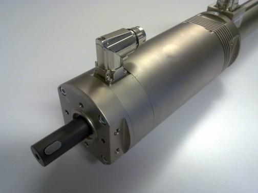
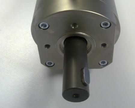
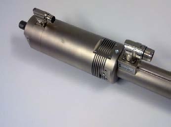
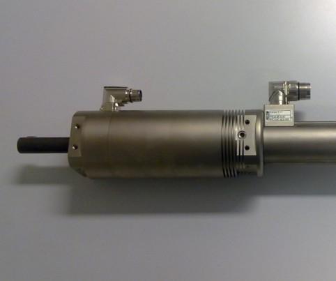
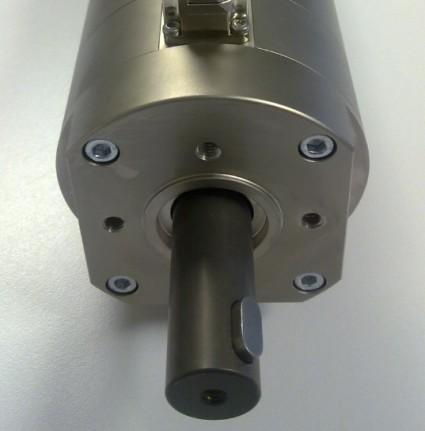
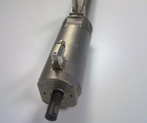
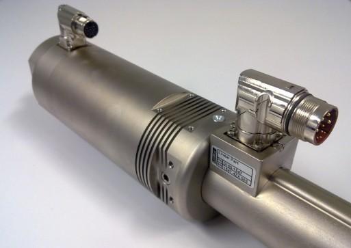
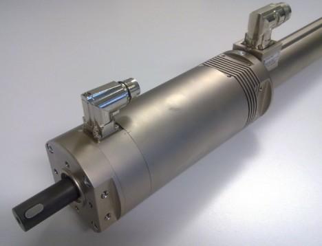
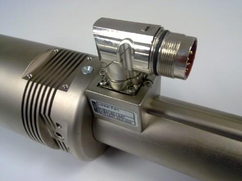
7 Overview LinMot PR01 Linear-Rotary Motors The LinMot PR01 series of Linear-Rotary motors includes various sizes that differ primarily in the maximum torque available from the rotary motor or the linear force available from the linear motor. In addition to the different sizes, variants with axial through-holes (for a pneumatic line or an ejector, for example) and stainless steel models are available. A Linear-Rotary motor fundamentally consists of a linear motor with an attached rotary torque motor. The two motors are electrically independent units and can be controlled completely independently of each other. 1. Rotary Motor 2. Linear Motor 3. Shaft (moves linear and rotating) 4. Slider of the Linear Motor (moves linear) 5. Option: Heat sinks for Linear Motor 6. Option: Clamp Set for load attachment 7. Option: Fan kit for Rotary Motor 8. Option: Wiper 9. Option: MagSpring kit UNO 10. Option: MagSpring kit DUO 11. Option: Cam kit NTI AG / LinMot E_2V96_IG_Linear_Rotary_Motors_PR01.odt 7/84
8 Part names Linear-Rotary motors are supplied fully assembled. The following list gives information about the individual components used. Variants model 52 PR01-52x40-R/37x120F-HP-C-80 (solid shaft) Part-No: PR01-52x40-R/37x120F-HP-C-80-L (hollow shaft) Part-No: PR01-52x60-R/37x120F-HP-C-100 (solid shaft) Part-No: PR01-52x60-R/37x120F-HP-C-100-L (hollow shaft) Part-No: PR01-52x60-R/37x120F-HP-C-150 (solid shaft) Part-No: PR01-52x60-R/37x120F-HP-C-150-L (hollow shaft) Part-No: Variants model 52 with planetary gear PR01-52x60-R/37x120F-HP-C-100-G05 gearbox 5:1 Part-No: PR01-52x60-R/37x120F-HP-C-100-G10 gearbox 10:1 Part-No: NTI AG / LinMot E_2V96_IG_Linear_Rotary_Motors_PR01.odt 8/84
9 Variants model 84 PR01-84x80-C/48x240F-C-100 (solid shaft) Part-No: PR01-84x80-C/48x240F-C-100-L (hollow shaft) Part-No: PR01-84x80-C/48x360F-C-100 (solid shaft) Part-No: PR01-84x80-C/48x360F-C-100-L (hollow shaft) Part-No: PR01-84x80-C/48x240F-C-300 (solid shaft) Part-No: PR01-84x80-C/48x240F-C-300-L (hollow shaft) Part-No: Variants model 84 in 'Stainless Steel' PR01-84x80-SSC-C/48x240F-C-150 (solid shaft, Stainless Steel ) Part-No: PR01-84x80-SSC-C/48x240F-C-150-L (hollow shaft, Stainless Steel ) Part-No: PR01-84x80-SSC-C/48x360F-C-150 (solid shaft, Stainless Steel ) Part-No: PR01-84x80-SSC-C/48x360F-C-150-L (hollow shaft Stainless Steel) Part-No: PR01-84x80-SSC-C/48x240F-C-300-L (hollow shaft Stainless Steel) Part-No: Variants model 84 with planetary gear PR01-84x80-C-G/48x240F-C-150-G05 gearbox 5:1 Part-No: PR01-84x80-C-G/48x240F-C-150-G07 gearbox 7:1 Part-No: PR01-84x80-C-G/48x240F-C-150-G10 gearbox 10:1 Part-No: PR01-84x80-C-G/48x360F-C-150-G05 gearbox 5:1 Part-No: PR01-84x80-C-G/48x360F-C-150-G07 gearbox 7:1 Part-No: PR01-84x80-C-G/48x360F-C-150-G10 gearbox 10:1 Part-No: NTI AG / LinMot E_2V96_IG_Linear_Rotary_Motors_PR01.odt 9/84
10 Technical data model 52 Unit PR01-52x40-R/ 37x120F-HP-C- 80 (-L) PR01-52x60- R/ 37x120F-HP- C-100 (-L) PR01-52x60-R/ 37x120F-HP-C- 150 (-L) Linear Motor* Max Stroke mm Short stroke range mm Peak Force **** N 255 (-L 229) 255 (-L 229) 255 (-L 229) Cont. Force with Fan **** N 92 (-L 82) 92 (-L 82) 92 (-L 82) Cont Force **** N 51 (-L 45) 51 (-L 45) 51 (-L 45) Max Velocity m/s Max Current A Force Constant N/A Repeatability mm +/ / / Phase Resistance (20 C) Ohm Phase Induction mh Linearity % +/ / /- 0.1 Rotary Motor* Peak Torque (stall) (M 0 Max) Nm Continuous Torque (stall) Nm Continuous Torque (stall) with Fan Recommended max revolution (n Max) Nm rpm Max Current** Arms Torque constant Nm/Arms NTI AG / LinMot E_2V96_IG_Linear_Rotary_Motors_PR01.odt 10/84
11 Unit PR01-52x40-R/ 37x120F-HP-C- 80 (-L) PR01-52x60- R/ 37x120F-HP- C-100 (-L) PR01-52x60-R/ 37x120F-HP-C- 150 (-L) Concentricity (max stroke without payload) mm <+/-0.05 <+/-0.05 <+/-0.07 Phase Resistance (20 C) Ohm Induction mh Repeatability +/ (+/-3') +/ (*/-3') +/ (*/-3') Mechanical Dimensions*** Length mm Diameter Linear Motor mm Diameter Rotary Motor mm Fitting Flange (front) mm Mass Total kg Moving mass (linear) kg Moment of inertia (rotation) kgcm Diameter shaft mm 12h9 12h9 12h9 Option hollow shaft ja ja ja Diameter hole 2.5 mm /max 6bar Connection: 2.5 mm/max 6bar Connection: 2.5 mm /max 6bar Connection: (-L version) (front) M5/ back (front) M5 / back (front) M5/ back 1/8 1/8 1/8 Protection Class IP54 IP54 IP54 Specification of products are subject to change without notification * with Drive E1200-UC series ** Attention: LinMot Talk shows peak current -->( Irms:= Ipeak/1.4) ***details see drawings **** hollow shaft versions -L: 10% reduced force (data in bracket) NTI AG / LinMot E_2V96_IG_Linear_Rotary_Motors_PR01.odt 11/84
12 Technical data model 52 with planetary gear Unit PR01-52x60-R/ 37x120F-HP- C-100-G05 PR01-52x60-R/ 37x120F-HP- C-100-G10 Linear Motor* Max Stroke mm Short stroke range mm Peak Force **** N Cont. Force with Fan **** N Cont Force **** N Max Velocity m/s Max Current A Force Constant N/A Repeatability mm +/ / Phase Resistance (20 C) Ohm Phase Induction mh Linearity % +/ /- 0.1 Rotary Motor* Peak Torque (stall) (M 0 Max) Nm Continuous Torque (stall) Nm Continuous Torque (stall) with Fan Recommended max revolution (n Max) Nm U/min Max Current** Arms Torque constant Nm/Arms NTI AG / LinMot E_2V96_IG_Linear_Rotary_Motors_PR01.odt 12/84
13 Einheit PR01-52x60-R/ 37x120F-HP- C-100-G05 PR01-52x60-R/ 37x120F-HP- C-100-G10 Gear ratio i 5 10 max revolution U/min Peak Torque (gearbox output) Nm 10 Nm 20 Nm Continuous Torque (gearbox output) Nm 2 Nm 4 Nm Phase Resistance (20 C) Ohm 3 3 Induction mh Repeatability +/ (*/-3') +/ (*/-3') Backlash of planetary gear arcmin <10 <10 Mechanical Dimensions*** Length mm Diameter Linear Motor mm Diameter Rotary Motor mm Mass Total kg Moving mass (linear) kg Moment of inertia (rotation) kgcm2 2 2 Option hollow shaft Protection Class IP54 IP54 NTI AG / LinMot E_2V96_IG_Linear_Rotary_Motors_PR01.odt 13/84
14 Technical data model 84 Unit PR01-84x80-C/ 48x240F- C-100 (-L) PR01-84x80-C/ 48x360F- C-100 (-L) PR01-84x80- SSC-C/ C-150 (-L) 48x240F- PR01-84x80- SSC-C/ C-150 (-L) PR01-84x80-C/ 48x360F- 48x240F-C- 300(-L) PR01-84x80- SSC-C/ 48x240F-C-300 (-L) Linear Motor* Max Stroke mm Short stroke range mm Peak Force**** N 572 (-L 514) 1024 (-L 921) 572 (-L 514) 1024 (-L 921) 572 (-L 514) 514 Cont. Force with Fan**** N 255 (-L 230) 354 (-L 319) 255 (-L 230) 354 (-L 319) Cont Force**** N 145 (-L 130) 203 (-L 182) 145 (-L 130) 203 (-L 182) Max Velocity m/s Max Current A Force Constant N/A Repeatability mm +/ / / / / / Phase Resistance (20 C) Ohm Rotary Motor* Phase Induction mh Peak Torque (stall) Linearity % +/ / / / / / (M 0 Max) Nm Continuous Torque (stall) Nm Continuous Torque (stall) mit Fan Recommended max revolution (n Max) Nm rpm Max Current** Arms Torque constant Nm/Arms NTI AG / LinMot E_2V96_IG_Linear_Rotary_Motors_PR01.odt 14/84
15 Unit PR01-84x80-C/ C-100 (-L) PR01-84x80-C/ C-100 (-L) 48x240F- 48x360F- PR01-84x80- SSC-C/ C-150 (-L) 48x240F- PR01-84x80- SSC-C/ C-150 (-L) PR01-84x80-C/ 48x240F-C-300 (-L) 48x360F- PR01-84x80- SSC-C/ 48x240F-C-300 (-L) Concentricity (max stroke without payload) mm <+/-0.05 <+/-0.05 <+/-0.07 <+/-0.07 <+/-0.3 <+/-0.3 Phase Resistance (20 C) Ohm Induction mh Repeatability +/ (*/-3') +/ (*/-3') +/ (*/-3') +/ (*/-3') +/ (*/-3') +/ (*/-3') Mechanical Dimensions*** Length mm Diameter Linear Motor mm Diameter Rotary Motor mm Fitting Flange (front) mm Mass Total kg Moving mass (linear) kg Moment of inertia (rotation) kgcm Diameter shaft mm 20h9 20h9 20h9 20h9 20h9 20h9 Option hollow shaft in shaft yes yes yes yes no yes Diameter hole (-L version) 4 mm / max 6 bar Back (slider) G1/4 Front (rod) : G1/8 4 mm / max 6 bar Back (slider) G1/4 Front (rod) : G1/8 4 mm / max 6 bar Back (slider) G1/4 Front (rod) : G1/8 4 mm / max 6 bar Back (slider) G1/4 Front (rod) : G1/8 4 mm / max 6 bar Back (slider) G1/4 Front (rod) : G1/8 4 mm / max 6 bar Back (slider) G1/4 Front (rod) : G1/8 Protection Class IP54 IP54 IP54 / IP65 IP54 / IP65 IP54 IP54 / IP65 Specification of products are subject to change without notification * with Drive E1200-UC series ** Attention: LinMot Talk shows peak current -->( Irms:= Ipeak/1.4) *** details see drawings **** hollow shaft versions -L: 10% reduced force (data in bracket) NTI AG / LinMot E_2V96_IG_Linear_Rotary_Motors_PR01.odt 15/84
16 Technical data model 84 with planetary gear Unit PR01-84x80-C/ 48x240F- C-150-G05 PR01-84x80-C/ 48x240F- C-150-G07 PR01-84x80-C/ 48x240F- C-150-G10 PR01-84x80-C/ 48x360F- C-150-G05 PR01-84x80-C/ 48x360F- C-150-G07 PR01-84x80-C/ 48x360F- C-150-G10 Linear Motor* Max Stroke mm Short stroke range mm Peak Force**** N Cont. Force with Fan**** N Cont Force**** N Max Velocity m/s Max Current A Force Constant N/A Repeatability mm +/ / / / / / Phase Resistance (20 C) Ohm Rotary Motor* Phase Induction mh Peak Torque (stall) Linearity % +/ / / / / / (M 0 Max) Nm Continuous Torque (stall) Nm Continuous Torque (stall) with Fan Recommended max revolution (n Max) Nm U/min Max Current** Arms Torque constant Nm/Arms NTI AG / LinMot E_2V96_IG_Linear_Rotary_Motors_PR01.odt 16/84
17 Unit PR01-84x80-C/ 48x240F-C-150- G05 PR01-84x80-C/ 48x240F-C-150- G07 PR01-84x80-C/ 48x240F-C-150- G10 PR01-84x80-C/ 48x360F-C-150- G05 PR01-84x80-C/ 48x360F-C-150- G07 PR01-84x80-C/ 48x360F-C-150- G10 Gear ratio i max revolution U/min Peak Torque (gearbox output) Nm Continuous Torque (gearbox output) Nm Phase Resistance (20 C) Ohm Induction mh Repeatability +/ (*/-3') +/ (*/-3') +/ (*/-3') +/ (*/-3') +/ (*/-3') +/ (*/-3') Backlash of planetary gear arcmin <10 <10 <10 <10 <10 <10 Mechanical Dimensions*** Length mm Diameter Linear Motor mm Diameter Rotary Motor mm Mass Total kg Moving mass (linear) kg Moment of inertia (rotation) kgcm Option hollow shaft in shaft Protection Class IP54 IP54 IP54 IP54 IP54 IP54 Specification of products are subject to change without notification * with Drive E1200-UC series ** Attention: LinMot Talk shows peak current -->( Irms:= Ipeak/1.4) *** details see drawings **** hollow shaft versions -L: 10% reduced force (data in bracket) NOTE: Gear box motors may regenerate a lot of energy into the DC-Link use drives with brake resistor or use additional DC-Link capacitor ( 10'000 uf) NTI AG / LinMot E_2V96_IG_Linear_Rotary_Motors_PR01.odt 17/84


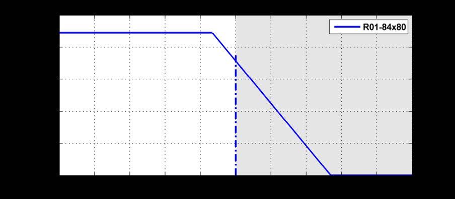
18 Torque-Speed Curve Rotary Motors NTI AG / LinMot E_2V96_IG_Linear_Rotary_Motors_PR01.odt 18/84
 is started up first.")
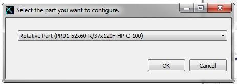
19 Startup The linear motor and rotary motor are electrically independent units. This means that the Linear-Rotary motor can be started up sequentially. It makes no difference which motor (linear or rotary) is started up first. Drive settings The various parameters for the linear motor and the rotary motor are set using the corresponding wizard in the LinMot Talk configuration program. (Contact LinMot Support if you do not see the folder "Motors\LinMot Linear Rotary Motor".) The Linear-Rotary motors are located in the folder "Motors\LinMot Linear Rotary Motors". It makes no difference whether the linear or rotary motor is configured first. NTI AG / LinMot E_2V96_IG_Linear_Rotary_Motors_PR01.odt 19/84


20 Configuration Linear Motor Configuration Rotary Motor NTI AG / LinMot E_2V96_IG_Linear_Rotary_Motors_PR01.odt 20/84

21 Homing the Rotary Motor No homing is necessary, because the rotary motor uses an absolute measurement system (single turn). Homing the Linear Motor If the linear motor is homed to the internal stop of the Linear-Rotary motor, then the maximum homing velocity must be no greater than 0.01 m/s. Example of VAI motion with Rotary Motor The LinMot Talk program uses units on the parameter page the same way they are used to actuate linear motors. In order to control a rotary motor, therefore, a ratio between one motor revolution (360 ) and the linear travel distance must be defined (by default, 1 revolution through 360 corresponds to a linear travel distance of 36 mm). Motor Wizard: Motor Angle to Position Ratio NTI AG / LinMot E_2V96_IG_Linear_Rotary_Motors_PR01.odt 21/84
22 The ratio can be freely defined. Keep in mind that the "position" parameter type is defined as a 32-bit value and the maximum position resolution is 0.1 µm. This means that the maximum stroke is limited to between mm and mm. Position [mm] to revolution = 36 mm (1 == 0.1 mm) Maximum number of revolutions = revolution = 360 mm (1 == 1 mm) Maximum number of revolutions = 1193 The ratio, however, affects not only the positions but also the PID controller. The table below shows an example of this: P [A/mm] 5 1 revolution = 36 mm (1 == 0.1 mm) For a deviation of 1, the drive reacts with 0.5 A 1 revolution = 360 mm (1 == 1 mm) For a deviation of 1, the drive reacts with 5 A This means that if the "Motor Angle to Position Ratio" is changed, the controller parameters must be (manually) adjusted as well. Example of motion using a VAI motion command A VAI Motion Command (motion using the Velocity Acceleration Interpolator) can be started directly via the LinMot Talk program. 1) Definition of the movement: Number of revolutions 25 Acceleration phase 100 [ms] Maximal velocity 1500 [rpm] Delay 50 [ms] 1 Revolution 36 [mm] 2) Converting the rotary parameters into the linear system: Target Position[mm]=Number of revolutions 36 [mm]=900[mm] Maximal Velocity [m/ s]=(1500[1/min] [m])/60=0.9[m/ s] Acceleration [m/s 2 ]=Maximal Velocity[m/ s]/0.1[s]=9[m/ s 2 ] Deceleration[m/ s 2 ]=Maximal Velocity [m/s]/0.05[ s]=18[m/ s 2 ] NTI AG / LinMot E_2V96_IG_Linear_Rotary_Motors_PR01.odt 22/84

23 3) Entering the parameters in LinMot-Talk Control Panel Motion Cmd Interface Using the oscilloscope (integrated in LinMot-Talk), the motion can be recorded and the PID control parameters can be adjusted as needed. Picture: LinMot-Talk - Oscilloscope NTI AG / LinMot E_2V96_IG_Linear_Rotary_Motors_PR01.odt 23/84


24 Notes on operating the Linear-Rotary Motor Running in the mechanical end stop may damage the motor During operation the linear motor must not be allowed to strike the upper or lower internal stops, as this can cause damage to the Linear-Rotary motor. The internal stops can be used for homing purposes, but the homing speed must not exceed the value of 0.01 m/s. Specially by using a MagSpring for the weight balancing and no payload is attached, the MagSpring may shoot the unit into the internal stop and damage the unit! Use an external stop ring attached to the rod or cable tie holding an adapter to prevent this situation. -->Do not remove the stop ring/cable tie as long as no payload is mounted! Pictures: External stop ring attached to the rod / cable tie holding an adapter Strategy for the linear and rotating movement The Linear-Rotary motor is designed to execute linear and rotary motions simultaneously. This means that the rotary and linear motions can be executed simultaneously and completely independent of one another. If the application permits, however, the following guidelines should be followed for physical technical reasons: Rotary motions should be performed with the linear axis retracted if possible, as this can reduce vibrations and mechanical loads due to asymmetrical load mass. Execute rotary and linear motions sequentially, which makes the load on the electrical power source more uniform and thus leads to greater energy efficiency. NTI AG / LinMot E_2V96_IG_Linear_Rotary_Motors_PR01.odt 24/84


25 Linear-Rotary Motors with planetary gear Linear-rotary motors with planetary gear will be used in all applications with high moment of inertia or high torque requirement. Model 52 with planetary gear Model 84 with planetary gear NTI AG / LinMot E_2V96_IG_Linear_Rotary_Motors_PR01.odt 25/84
. The rotary axis is sealed against the stator.")
26 Stainless steel variant of the PR01-84x80-SSC series In addition to standard Linear-Rotary Motors, variants made of chromium steel are available in the PR01-84 series. Both the front flange and the rotary axis are made of chromium steel (V4A). The rotary axis is sealed against the stator. For maintenance purposes, the front Part of the flange, where the seals and guides are located, can be removed. The Linear-Rotary motor does not need to be removed from the system in order to remove the flange. Picture: Linear-Rotary Motor PR01-84x80-SSC-C/ 48x240F-C-150 Picture: Front part of the flange, includes sealing and bearings, can be replaced easily. Normally the complete front part with all seals and bearings will be replaced. In case that the seals and bearings are only cleaned the following lubricant has to be used: fin food Grease 2 from INTERFLON NTI AG / LinMot E_2V96_IG_Linear_Rotary_Motors_PR01.odt 26/84

27 Notes on application of the PR01-84x80-SSC series The design of the machine should consist of a 'normal' and a 'stainless steel' zone. The 'stainless steel zone' can be cleaned accordingly during operation. The two zones are separated by a stainless steel plate. The flange of the Linear-Rotary motor, also made of stainless steel, is inserted through this steel plate. The cylindrical front end of the flange has a groove with an O-ring that acts as a seal between the 'normal' and the stainless steel zones. Picture: O-ring for sealing between 'normal' and 'stainless steel' zone. Notes on cleaning the SSC variants The rotary axis should not be set in motion while the line is being cleaned. It should be either fully extended or fully retracted. The chromium steel zone has IP65 class protection. The seals are made from FKM fluorelastomer and 85 AU polyester-urethane rubber. Note Linear-Rotary units with new or replaced seals will show an increased friction on both movements (linear and rotation) during the first hours of operation. NTI AG / LinMot E_2V96_IG_Linear_Rotary_Motors_PR01.odt 27/84

28 Special Application Example: Linear-Rotary motors on a turntable Picture: Typical arrangement of a system with Linear-Rotary motors and drives on a turntable. The lowest turntable is the divider between the 'stainless steel' and 'normal' zones. The drives for actuating the motors are located above the Linear-Rotary motors. NTI AG / LinMot E_2V96_IG_Linear_Rotary_Motors_PR01.odt 28/84
29 Cam profile for E-stop in applications with rotary disk A fast turning rotary disk can not be stopped quickly during a loss of power emergency. This means the linearrotary motor could be damaged if the rod is unpowered in the extended position and collides with other fixtures or tooling. An emergency guide profile at the point of possible collision helps to solve this situation by lifting the slider motor into the up position to prevent damage to other machinery. The following picture shows a possible application of a Cam kit MF01-PK84 (Part-No ). Cam kit forces the Linear Rotary Motor trough the pulley upwards. Picture: At the critical position the crank forces the moving part of the linear-rotary motor up in case of a power breakdown. (Caution: Mechanical end stop is not shown!) Caution: Make sure that the Cam kit or any other auxiliary equipment that pulls or pushes the Linear-Rotary Motor upwards has its own mechanical stop. Linear-Rotary Motor internal collisions may not be used as an end stop in any case. Using Linear-Rotary Motor internal collisions may damage the unit. In addition the motor must be supported (see chapter Installing Linear-Rotary Motors) to absorb any side load of the crank. NTI AG / LinMot E_2V96_IG_Linear_Rotary_Motors_PR01.odt 29/84
30 Installing Linear-Rotary Motors The PR01 Linear-Rotary motors have a center fit on the front side so that the rotary axis can be precisely aligned. Due to the narrow construction of the Linear-Rotary motors, it is most often not sufficient to mount them by the front bolts alone (due to vibration or lateral loads). An additional support is then necessary. From a technical point of view the support should be done at the end of the motor to reduce any oscillations. Note that tolerances must be compensated (e.g. through long holes) to eliminate any tension to the motor between the two mounting points. The following sketches show examples of the various possibilities. The chapter on installation drawings contains detailed dimensions. Front mounting with side support Bottom mounting, mounted through linear-rotary side mounting holes Compensate tolerance using a washers (if necessary), when the linear-rotary is fixed through bottom mounting holes Angle and heat sinks support NTI AG / LinMot E_2V96_IG_Linear_Rotary_Motors_PR01.odt 30/84
31 Support through cooling flange side section Support through the side section at the end of Linear motor Support through the Multifunction-Flange side section NTI AG / LinMot E_2V96_IG_Linear_Rotary_Motors_PR01.odt 31/84
32 Drawings of Linear-Rotary motors with accessories Linear-Rotary Motor without accessories Linear-Rotary Motor Motor with backside whipper Linear-Rotary Motor with fan kit for cooling of the Rotary Motor NTI AG / LinMot E_2V96_IG_Linear_Rotary_Motors_PR01.odt 32/84


33 Linear-Rotary Motor with two MagSprings Linear-Rotary Motor with Cam kit Linear-Rotary Motor with MagSpring kit UNO, mounting and heat sinks NTI AG / LinMot E_2V96_IG_Linear_Rotary_Motors_PR01.odt 33/84

34 Linear-Rotary Motor with MagSpring kit UNO, and flange CAD-Files CAD files and STEP files can be downloaded from the CAD download area on the webpage at NTI AG / LinMot E_2V96_IG_Linear_Rotary_Motors_PR01.odt 34/84


35 Accessories Heat sinks for linear motors The following heat sinks, in various lengths, help to cool the linear motor. Option heat sink for linear motor PS01-37x120F-HP-C-.. Article Article L [mm] Mass [kg] Part- No PC01-37x68 heat sink Option heat sink for linear motor PS01-48x240F-C-... and PS01-48x360F-C-... Article Article L [mm] Mass [kg] Part- No PC01-48x100 heat sink PC01-48x117 heat sink NTI AG / LinMot E_2V96_IG_Linear_Rotary_Motors_PR01.odt 35/84


36 Mounting and cooling flange for linear motors The following flanges, in various lengths, are used to mount the Linear-Rotary motor as well as cool the linear motor. Option mounting and cooling flange for Linear Motor PS01-37x120F-HP-C-.. Article Article L [mm] A [mm] B [mm] Mass [kg] Part- No PF02-37x100 Flange 37x100 mm PF02-37x140 Flange 37x140 mm Option mounting and cooling flange for Linear Motors PS01-48x240F-C-... PS01-48x360F-C-... Article Article L [mm] B [mm] Mass [kg] Part- No PF01-48x120 Flange 48x120 mm PF01-48x226 Flange 48x226 mm NTI AG / LinMot E_2V96_IG_Linear_Rotary_Motors_PR01.odt 36/84


37 Fan kits Fan kits are available for both the rotary motor and the linear motor. In general, forced ventilation allows the continuous torque or force to be increased (see design program). Fan kits for Linear Motor Option: Fan for Linear Motor PS01-37x120F-HP-C-.. Connection: 24VDC / 120mA Article fan for Part-No HV01-37/48* Fan Kit for H01-37, B01-37 and PF * order separate mounting and cooling Flange PF02-37x100 or PF02-37x140 Option: Fan for Linear Motor PS01-48x240F-C-.. / PS01-48x360F-C-... Connection: 24VDC / 120 ma Article fan for Part-No HV01-37/48* Fan Kit for H01-48, B01-48 and PF * order separate mounting and cooling Flange PF01-48x120 or PF01-48x226 NTI AG / LinMot E_2V96_IG_Linear_Rotary_Motors_PR01.odt 37/84


38 Fan kit for Rotary Motors Option: fan for Rotary Motor model 52 Connection: red= 24Vdc blue or black=gnd Article fan for Mass Part-No RS01-VA52-Kit Rotary Motor RS kg Option: fan for Rotary Motor model 84 Connection: red= 24Vdc blue or black=gnd Article fan for Mass Part-No RS01-VA84-Kit Rotary Motor RS kg NTI AG / LinMot E_2V96_IG_Linear_Rotary_Motors_PR01.odt 38/84
39 Wipers The rotary axis is protected against dirt and loss of grease by a wiper on the front side. The back side of the linear motor slider should also be protected by means of a wiper. The options 'wiper' and 'multifunctional flange' are available for this. A L D Description Part- No. D L A Mass Wipers for model 52 PS01-37x120F-HP-C-.. PA01-37/20-F mm (1.77in) 32mm (1.26in) 12mm (0.47in) 0.028kg Wipers for model 84 PS01-48x240F-C-... PS01-48x360F-C-... PA01-48/28-F mm (2.28in) 32mm (1.26in) 14mm (0.55in) 0.056kg NTI AG / LinMot E_2V96_IG_Linear_Rotary_Motors_PR01.odt 39/84

40 Multifunction flange and MagSpring The multifunctional flange can perform one or more of the following functions: - Wiper for the linear motor slider - Mounting a MagSpring spring for load compensation - Mounting a pneumatic brake - Mounting element for the Linear-Rotary motor Effective force of the MagSpring Depending on the orientation of the MagSpring slider, the effect of the force can be modified. This means that the MagSpring pulls the rotary axis of the Linear-Rotary motor inward, or pushes it outward. Top: 'Pushing' MagSpring Bottom:'Pulling' MagSpring Specially by using a MagSpring for the weight balancing and no payload is attached, the MagSpring may shoot the unit into the internal stop and damage the unit! Use an external stop ring attached to the rod to prevent this situation Picture: External stop ring attached to the rod NTI AG / LinMot E_2V96_IG_Linear_Rotary_Motors_PR01.odt 40/84
 Description / Part.-No for model 84 and 84- L UNO MF01-PR01-84x37-1 Part.-No. 0250-2337 PAW01-28 / Part.")
41 1 Multifunction flange MF01-PR01-52x40-20 Part.-No Description / Part- No for for 20 N MagSpring model 52 and 52 -L MF01-PR01-52x40-37 Part.-No for 40/60 N MagSpring 2 Wiper PAW01-20 / Part.-No (delivered with Pos 1) Description / Part.-No for model 84 and 84- L UNO MF01-PR01-84x37-1 Part.-No PAW01-28 / Part.-No (delivered with Pos 1) 3 Spacer washer Spacer washer (delivered with Pos 1) 4 MagSpring Stator 5 MagSpring Slider 22 N force MS01-20x140 Part.-No N force ML01-12x350/ Part.-No MagSpring Adapter MA01-PR /20 Part.-No Spacer sleeve MA01-PR01-Huelse 4,9 40 N force MS01-37x155 Part.-No N force MS01-37x155 Part.-No N force ML01-12x350/ Part.-No N force: ML01-12x350/ Part.-No Part.-No (delivered with Pos 6) 60 N force MS01-37x155 Part.-No N force ML01-12x350/ Part.-No MA01-PR01-84x80-37x1 Part-No MA01-PR01-Huelse 4,9 Part.-No (delivered with Pos 6) 8 Socket screw M5x14 / ISO 4762 (delivered with Pos 6) M5x14 / ISO4762 (delivered with Pos 6) 9 Pneumatic fitting for 6mm hose 1/8 (delivered with Pos 6) for 10mm hose 1/ 4 (delivered with Pos 6) 10 Socket screw M8x18 / ISO 4762 (delivered with Pos 6) M10x20 / DIN 7984 (delivered with Pos 6) 11 Adjusting washer M8 (delivered with Pos 6) M10 (delivered with Pos 6) 12 Socket screws 2x M5x30 / ISO 4762 (delivered with Pos 1) 2x M5x35 / ISO 4762 (delivered with Pos 1) NTI AG / LinMot E_2V96_IG_Linear_Rotary_Motors_PR01.odt 41/84

42 Description / Part.-No for model 84 DUO and 84 -L DUO 1 Multifunction flange MF01-PR01-84x37-2 / Part.-No Wiper PAW01-28 / Part.-No (delivered with Pos 1) 3 Spacer washers 2x Spacer washers (delivered with 1) 4 MagSpring Stators 2x 60 N force 2x MS01-37x155 Part.-No MagSpring Sliders 2x 60 N force 2x ML01-12x350/ Part.-No MagSpring Adapters MA01-PR01-84x Part.-No Spacer sleeves 2x MA01-PR01-Huelse 4,9 Part.-No (delivered with Pos 6) 8 Socket screws 2x M5x14 / ISO 4762 (delivered with Pos 6) 9 Pneumatic fitting for 10mm hose 1/ 4 (delivered with Pos 6) 10 Socket screws M10x20 / DIN 7984 (delivered with 6) 11 Adjusting washer M10 (delivered with Pos 6) 12 Socket screws 2x M5x35 / ISO 4762 (delivered with Pos 1) NTI AG / LinMot E_2V96_IG_Linear_Rotary_Motors_PR01.odt 42/84

43 Dimensions multifunction flanges for mounting of MagSpring Stator Material: Al anodized Description Part- No L B H Mass Multifunction flange for model 52 and MagSpring MS Multifunction flange for model 52 and MagSpring MS Multifunction flange for model 84 and MagSpring MS Multifunction flange for model 84 and 2x MagSpring MS MF01-PR01-52x mm 40 mm 50 mm 0.33 kg MF01-PR01-52x mm 40 mm 50 mm 0.31 kg MF01-PR01-84x mm 40 mm 60 mm kg MF01-PR01-84x mm 40 mm 80 mm kg NTI AG / LinMot E_2V96_IG_Linear_Rotary_Motors_PR01.odt 43/84

44 Dimensions adapter for mounting of MagSpring-Slider Material: Al anodized Description Part- No. L B H Mass 1 Adapter for model 52 MA01-PR01-52x37/ mm 22 mm 10 mm 0.05 kg 2 3 Adapter for model 84 and MagSpring MS Adapter for model 84 and 2x MagSpring MS MA01-PR01-84x mm 30 mm 10 mm kg MA01-PR01-84x mm 55 mm 15 mm kg NTI AG / LinMot E_2V96_IG_Linear_Rotary_Motors_PR01.odt 44/84
45 Cam kit MF01-PK84 Application as Emergency Crank For the application as an emergency crank a pulley (not included) can be mounted at the side of the adapter (thread M10). Through can be ensured a forced movement in a linear direction. Description / Part.-No. for MF01-PK84 Part.-No Cam flange MF01-PR01-84x80-K Part.-No Wiper PAW01-28 Art.-No Linear ball bearings 2x LBBR 12-2LS Part.-No Guiding rods 2x MF01k-KS12x200 Länge 200 mm Part.-No Shaft seals 2x SP-12x19x3 Part.-No Cam kit adapter MA01-PR01-84x80-K Part.-No Socket crews 2x M5x35 / ISO Schrauben Inbus 2x M5x14 / ISO Pneumatic fitting for 10mm hose 1/ 4 10 Socket screw M10x20 / DIN Adjusting washer M10 Order information: Cam kit MF01-PK84 (incl. 1-11) NTI AG / LinMot E_2V96_IG_Linear_Rotary_Motors_PR01.odt 45/84


46 Dimensions Cam flange Material: Al anodized L B H Mass Cam flange individual part 102 mm 60 mm 80 mm kg Dimensions Cam adapter Material: Al anodized L B H Mass Cam adapter individual part 85 mm 55 mm 12 mm kg NTI AG / LinMot E_2V96_IG_Linear_Rotary_Motors_PR01.odt 46/84
 model 52 22 N MS01-20x140 0250-2201 140 mm 20 mm 0.18 kg model 52 40N / 60 N MS01-37x155 0250-2204 155 mm 37 mm 0.88 kg model 84 60 N MS01-37x155 0250-2204 155 mm 37 mm 0.")
47 Magnetic spring MagSpring Dimension MagSpring Stator MS01-20x140 Dimension MagSpring Stator MS01-37x155 MagSpring Stator Force (depending Article Part- No. L D Mass on slider) model N MS01-20x mm 20 mm 0.18 kg model 52 40N / 60 N MS01-37x mm 37 mm 0.88 kg model N MS01-37x mm 37 mm 0.88 kg MagSpring Slider Force Article Part- No. L D Mass model N ML01-12x350/ mm 12 mm kg model N ML01-12x350/ mm 12 mm kg model N ML01-12x350/ mm 12 mm kg model N ML01-12x350/ mm 12mm kg Example: Linear-Rotary Motor model 52 with MagSpring of force 40N: Stator: MS01-37x155 Slider: ML01-12x350/ Linear-Rotary Motor model 52 with MagSpring of force 60N: Stator: MS01-37x155 Slider: ML01-12x350/ NTI AG / LinMot E_2V96_IG_Linear_Rotary_Motors_PR01.odt 47/84

48 Load attachment Because both a rotary and a linear motion are performed, the type of attachment must be selected such that it can support both torques and longitudinal forces. Clamp sets that enable fast, easy mounting of the load Mass are available as accessories. They provide a force-fit connection that is created by two conical rings. This completely eliminates the need for inserting lugs or producing grooves. Technical data RS01-SS12x22 : Tmax: 20Nm Fmax: 3kN Tolerance for fit D: 22H9 mm RS01-SS20x38: Tmax: 160Nm Fmax: 15kN Tolerance for fit D: 38H9 mm Clamp set for model 52 Clamp set for model 84 Article Part- No. d D L Lges Mass RS01-SS12x mm 22 mm 13 mm 15.5 mm 22g RS01-SS20x mm 38 mm 21 mm 26 mm 100g NTI AG / LinMot E_2V96_IG_Linear_Rotary_Motors_PR01.odt 48/84
49 Connector assignment Connector assignment Linear Motors Stecker Typ C-Connector Pin Phase 1+ A Phase 1- B Phase 2+ C Phase 2- D +5V E GROand* F Sensor Sinus G Sensor Cosinus H Temp. Sensor L Shield* Casing Connector assignment Rotary Motors Stecker Typ C-Connector R-Connector Pin Pin Phase A A 1 Phase B B 2 Phase C C 3 NC D 4 +5V E A GROUND* F B Sensor Sinus G C Sensor Cosinus H D Temp. Sensor L E Schirm* Gehäuse Gehäuse Extension cables are double shielded. The two shields of the extension cables must not be connected together: The inner shield of the extension cables is used as GROand and must be connected to GROand*, only the outer shield must be connected to SHIELD* of the connectors. Caution: Do not connect or disconnect motor when there is power on the controller. Double-check each connection! Wrong connections can destroy controller and stator! NTI AG / LinMot E_2V96_IG_Linear_Rotary_Motors_PR01.odt 49/84
50 Drawings Drawing PR01-52x40-R/37x120F-HP-C-80 NTI AG / LinMot E_2V96_IG_Linear_Rotary_Motors_PR01.odt 50/84
51 Stroke range PR01-52x40-R/37x120F-HP-C-80 NTI AG / LinMot E_2V96_IG_Linear_Rotary_Motors_PR01.odt 51/84
52 Drawing PR01-52x60-R/37x120F-HP-C-100 NTI AG / LinMot E_2V96_IG_Linear_Rotary_Motors_PR01.odt 52/84
53 Stroke range PR01-52x60-R/37x120F-HP-C NTI AG / LinMot E_2V96_IG_Linear_Rotary_Motors_PR01.odt 53/84
54 Drawing PR01-52x60-R/37x120F-HP-C-100 with Flange PF02-37x100 NTI AG / LinMot E_2V96_IG_Linear_Rotary_Motors_PR01.odt 54/84
55 Drawing PR01-52x60-R/37x120F-HP-C-100 with MagSpring NTI AG / LinMot E_2V96_IG_Linear_Rotary_Motors_PR01.odt 55/84
56 Drawing PR01-52x60-R/37x120F-HP-C-100 Flange/MagSpring/Fan NTI AG / LinMot E_2V96_IG_Linear_Rotary_Motors_PR01.odt 56/84
57 Drawing PR01-52x60-R/37x120F-HP-C-150 NTI AG / LinMot E_2V96_IG_Linear_Rotary_Motors_PR01.odt 57/84
58 Stroke range PR01-52x60-R/37x120F-HP-C-150 NTI AG / LinMot E_2V96_IG_Linear_Rotary_Motors_PR01.odt 58/84

59 Drawing PR01-52x60-R/37x120F-HP-C-100-G.. NTI AG / LinMot E_2V96_IG_Linear_Rotary_Motors_PR01.odt 59/84
60 Stroke range PR01-52x60-R/37x120F-HP-C-100-G.. NTI AG / LinMot E_2V96_IG_Linear_Rotary_Motors_PR01.odt 60/84
61 Drawing PR01-84x80-C/48x240F-C-100 NTI AG / LinMot E_2V96_IG_Linear_Rotary_Motors_PR01.odt 61/84
62 Stroke range PR01-84x80-C/48x240F-C-100 NTI AG / LinMot E_2V96_IG_Linear_Rotary_Motors_PR01.odt 62/84
63 Drawing PR01-84x80-C/48x240F-C-100 with Flange PF01-48x226 NTI AG / LinMot E_2V96_IG_Linear_Rotary_Motors_PR01.odt 63/84
64 Drawing PR01-84x80-C/48x240F-C-100 Multifunction-Flange and MagSpring NTI AG / LinMot E_2V96_IG_Linear_Rotary_Motors_PR01.odt 64/84
65 Drawing PR01-84x80-C/48x240F-C-100 with Flange and MagSpring NTI AG / LinMot E_2V96_IG_Linear_Rotary_Motors_PR01.odt 65/84
66 Drawing PR01-84x80-C/48x360F-C-100 NTI AG / LinMot E_2V96_IG_Linear_Rotary_Motors_PR01.odt 66/84
67 Stroke range PR01-84x80-C/48x360F-C-100 NTI AG / LinMot E_2V96_IG_Linear_Rotary_Motors_PR01.odt 67/84
68 Drawing PR01-84x80-SSC-C/48x240F-C-150 NTI AG / LinMot E_2V96_IG_Linear_Rotary_Motors_PR01.odt 68/84
69 Stroke range PR01-84x80-SSC-C/48x240F-C-150 NTI AG / LinMot E_2V96_IG_Linear_Rotary_Motors_PR01.odt 69/84
70 Drawing PR01-84x80-SSC-C/48x360F-C-150 NTI AG / LinMot E_2V96_IG_Linear_Rotary_Motors_PR01.odt 70/84
71 Stroke range PR01-84x80-SSC-C/48x360F-C-150 NTI AG / LinMot E_2V96_IG_Linear_Rotary_Motors_PR01.odt 71/84
72 Drawing PR01-84x80-C / RS01-84x80-SSC-C / 48x240F-C-300 NTI AG / LinMot E_2V96_IG_Linear_Rotary_Motors_PR01.odt 72/84
73 Stroke range PR01-84x80-C / RS01-84x80-SSC-C / 48x240F-C-300 NTI AG / LinMot E_2V96_IG_Linear_Rotary_Motors_PR01.odt 73/84

74 Drawing PR01-84x80-C/48x240F-C-150-G.. NTI AG / LinMot E_2V96_IG_Linear_Rotary_Motors_PR01.odt 74/84
75 Stroke Range PR01-84x80-C/48x240F-C-150-G.. NTI AG / LinMot E_2V96_IG_Linear_Rotary_Motors_PR01.odt 75/84

76 Drawing PR01-84x80-C/48x360F-C-150-G.. NTI AG / LinMot E_2V96_IG_Linear_Rotary_Motors_PR01.odt 76/84
77 Stroke Range PR01-84x80-C/48x360F-C-150-G.. NTI AG / LinMot E_2V96_IG_Linear_Rotary_Motors_PR01.odt 77/84
 one inspection every 3 months is adequate.")
78 Maintenance of LinMot Linear-Rotary Motors LinMot Stators will be shipped with an initial lubrication. Maintenance will only be required if the motors run 'dry' or there is a heavy pollution of the motors. Under normal industrial conditions (5 day, 8h/day) one inspection every 3 months is adequate. Where conditions differ, as with severe and permanent fouling, direct sunshine, operation out in the open, increased operating temperature etc., the maintenance intervals must be shortened till empirical values for the particular application are obtained. Inspection Inspections have to be executed according to the operating condition and the load of motors. Following points have to be checked during inspection: Is a film of lubricant on the slider? Is the wiper (if existent) without visible wear? Is the lubricant not adhesive? Can the slider be moved easily? If the motors are heavily polluted respectively if no film of lubricant is on the slider, then stators and sliders must be cleaned and lubricated again. Cleaning and lubrication Disassembling and cleaning If existing, remove wiper (1) from the stator. Open fastening screws (2a, 2b and if existing 2c) between rotary motor and linear motor. Pull the stator (2) rapidly back over the slider (5) to prevent sticking to the Stator (3). Don't attempt to loosen the slider (5) from the rod (6). Attention: huge magnetic attraction of the slider! Clean slider (5), stator (3) and grooves (6) with cleaning agent LU06. NTI AG / LinMot E_2V96_IG_Linear_Rotary_Motors_PR01.odt 78/84
79 Lubrication and assembling Lubricate the grooves (6) with 2-3 g (0.1 oz.) LU02. Lubricate the bore of the stators (3) with about 2-3 g (=0.1 oz.) lubricant LU02. There should only be a slight film of lubricant. Do not over lubricate! Lubricate the slider (5) with a soft fabric or manually. 4 g of lubricant per meter slider is enough to create a film of lubricant on the surface of the sliders. (4 g (0.14 oz.) is about ½ of a hazelnut). Do not over lubricate! Especially in higher operating temperatures, over lubrication can lead to a gumming of the lubricant. (In such a situation the motor must be cleaned completely.) If wipers are used then the inner side of the seals of the wipers must be lubricated as well. Do not lubricate outside of the wipers! Assembling: move the mounting ring (7) adjusted into the stator (3). Make sure that the slider (5) is centered with a cardboard or wood wrapping because of the magnetic attraction to the outside of the stator (3). Then move the stator (3) over the slider (5). Tighten the fastening screws 2a and 2b simultaneously to make sure the slider, stator, and rotary motor are concentric. If existing then tighten screw 2c lightly in the same manner. Use bolt lock (medium). Lubricant The lubricant reduces the friction between the chromium-nickel steel surface of the slider and the reinforced plastic plain bearing. LinMot Lubricant LU02 Art. No (8g) LinMot Lubricant LU02 Art. No (50g) LinMot Lubricant LU02 Art. No (1000g) LinMot LU02 Lubricant corresponds to KLÜBERSYNTH UH which was developed for the food processing industry. Cleaning Agent The following Cleaning Agent spray is recommended for LinMot Stators and Sliders: LinMot Spray LU (250ml) Art. No LinMot LU06 Lubricant corresponds to KLÜBERSYNTH NH1 4 2 which was developed for the food processing industry. Storage / transport Sliders are to be stored and transported only in the plastic containers (with cardboard inlay) provided for this, or already fitted in LinMot motors and secured. Maximum storage temperature: 70 C NTI AG / LinMot E_2V96_IG_Linear_Rotary_Motors_PR01.odt 79/84
80 Trouble Shooting Trouble Shooting of Linear Motors The following tables show the resistive value between the different connector pins for each stator type. If the value is not in a range of +/- 10% the stator may be damaged (temperature of the stator for all measurements: 20 C). PS01 37x120F-HP-C-80 /-100 / -150 Phase1+ / Phase1- Pin A / Pin B 2.6 Phase2+ / Phase2- Pin C / Pin D 2.6 5V / GND Pin E / Pin F 155 Sensor Sinus / GND Pin G / Pin F 33 k Sensor Cosine / GND Pin H / Pin F 33 k Temp. Sensor / GND Pin L / Pin F 10k Phase / GND Pin A,B,C,D / Pin F >20 M All Pin / Shield Pin A-L / Housing >20 M PS01 48x240F-C-100 (-150, -300) Phase1+ / Phase1- Pin A / Pin B 1.1 Phase2+ / Phase2- Pin C / Pin D 1.1 5V / GND Pin E / Pin F 155 Sensor Sin / GND Pin G / Pin F 33 k Sensor Cos / GND Pin H / Pin F 33 k Temp. Sensor / GND Pin L / Pin F 10 k Phase / GND Pin A,B,C,D / Pin F >20 M Alle Pins / Shield Pin A-L / Gehäuse >20 M PS01 48x360F-C-100 (-150) Phase1+ / Phase1- Pin A / Pin B 1.5 Phase2+ / Phase2- Pin C / Pin D 1.5 5V / GND Pin E / Pin F 155 Sensor Sin / GND Pin G / Pin F 33 k Sensor Cos / GND Pin H / Pin F 33 k Temp. Sensor / GND Pin L / Pin F 10 k Phase / GND Pin A,B,C,D / Pin F >20 M Alle Pins / Shield Pin A-L / Gehäuse >20 M NTI AG / LinMot E_2V96_IG_Linear_Rotary_Motors_PR01.odt 80/84
LinMot Linear-Rotary Motors Version 2.96e
 LinMot Linear-Rotary Motors Version 2.96e 1/84 CAUTION LINMOT SLIDERS CONTAIN NEODYMIUM MAGNETS WHICH MAY DISTURB OR DAMAGE MAGNETIC DATA CARRIERS AND DELICATE ELECTRONIC EQUIPMENT MERELY BY COMING CLOSE
LinMot Linear-Rotary Motors Version 2.94e
 LinMot Linear-Rotary Motors Version 2.94e NTI AG / LinMot 1/79 CAUTION LINMOT SLIDERS CONTAIN NEODYMIUM MAGNETS WHICH MAY DISTURB OR DAMAGE MAGNETIC DATA CARRIERS AND DELICATE ELECTRONIC EQUIPMENT MERELY
LinMot Linear-Rotary Motors
 LinMot Linear-Rotary Motors Version 2.6e NTI AG / LinMot www.linmot.com PR_MotorSeries-V2.6e.odt 1/71 CAUTION LINMOT SLIDERS CONTAIN NEODYMIUM MAGNETS WHICH MAY DISTURB OR DAMAGE MAGNETIC DATA CARRIERS
Linear Rotary Motors. Linear-Rotary Motors. The linear motor technology for industrial applications. Linear and rotary direct drive
 Linear Rotary Motors Linear-Rotary Motors Linear and rotary direct drive Independent linear and rotary motion Synchronised linear and rotary motion Programmable press force up to 1 24N Programmable tightening
Version 1.67e E_1V67_IG_Linear_Guides_F01.odt 1/61
 LinMot F01-37S and F01-48 Guides Version 1.67e www.linmot-usa.com 0185-0026-E_1V67_IG_Linear_Guides_F01.odt 1/61 CAUTION LINMOT SLIDERS CONTAIN NEODYMIUM MAGNETS WHICH MAY DISTURB OR DAMAGE MAGNETIC DATA
LinMot F01-37S Guide. Version 1.59e. NTI AG / E_1V59_IG_Linear_Guides_F01-37.odt 1/40
 LinMot F01-37S Guide Version 1.59e NTI AG / www.linmot.com 0185-0026-E_1V59_IG_Linear_Guides_F01-37.odt 1/40 CAUTION LINMOT SLIDERS CONTAIN NEODYMIUM MAGNETS WHICH MAY DISTURB OR DAMAGE MAGNETIC DATA CARRIERS
Assembly Instructions for H- and B Guide with Linear Motor
 Assembly Instructions for H- and B Guide with Linear Motor Version 1.2 H-Guide Series: H01-23x86/... H01-23x166/... H01-37x166/.. H01-37x286/... H01-48x250/... B01-48x250/... B-Guide Series B01-37x166/..
Linear Motors & Servo Drives 3x400VAC. Linear Motor Series P The linear motor technology for industrial applications. Peak force up to 2 500N
 Linear Motors & Servo Drives 3x400VAC Linear Motor Series P10- Peak force up to 2 500N Velocity up to 5m/s Acceleration up to 100g Free positioning Long life: Linear direct drive The linear motor technology
Installation Guide Linear Guides H01-23 / 37 / 48
 H01-23 / 37 / 48 NTI AG / LinMot Dok-Nr. 0185-0083-E_1V1_IG_Linear_Guides_H01 Content 1 General information... 4 Introduction... 4 Explanation of symbols... 4 Qualified personnel... 4 Liability... 4 Copyright...
MagSpring Magnetic Springs
 MagSpring Magnetic Springs MagSpring, unlike mechanical springs, deliver a constant force over their entire working rang MagSpring, consists of only two components: a stator and a slider MagSprings are
1. Product overview Basic-Line-Module AXN Product description Basic-Line-Module AXN 4-5. Guide system Roller guide 6 Drive system Gear belt 7
 Directory Page 1. Product overview Basic-Line-Module AXN 3 2. Product description Basic-Line-Module AXN 4-5 Guide system Roller guide 6 Drive system Gear belt 7 3. Basic-Line-Modul AXN 45-Z 8-9 AXN 65-Z
Courtesy of CMA/Flodyne/Hydradyne Motion Control Hydraulic Pneumatic Electrical Mechanical (800)
") P01 LinMot P is a family of linear direct drives for highly dynamic motions. The motor is made up of just two parts: the slider and the stator. The two parts are not connected by brushes or cables. The
P01 LinMot P is a family of linear direct drives for highly dynamic motions. The motor is made up of just two parts: the slider and the stator. The two parts are not connected by brushes or cables. The
MagSpring. Courtesy of Steven Engineering, Inc. - (800)
") 468 www.linmot.com M01-20 472 M01-37 474 Accessories 476 www..com 469 products can best be described as "magnetic springs." The term "spring", however, is to be understood to mean that components generate
468 www.linmot.com M01-20 472 M01-37 474 Accessories 476 www..com 469 products can best be described as "magnetic springs." The term "spring", however, is to be understood to mean that components generate
The linear motor technology for industrial applications
 Industrial Linear Motors Purely electrical drive system Freely positionable along the entire stroke For precise and dynamic positioning tasks Direct drive technology provides longer life Clean room certification
Linear Motor Series P10-70
 Linear Motor Series P10- Peak force up to 2 500N Velocity up to 5m/s Acceleration up to 100g Free positioning Long life: Linear direct drive The linear motor technology for industrial applications LinMot
V SWISS MADE LINEAR TECHNOLOGY
 Compact units Excerpt from main catalogue SWISS MADE LINEAR TECHNOLOGY V 11-15 Line Tech compact units Table of contents Product overview 106 107 Design fundamentals / Lubrication / Maintenance 108 Profile
Linear Drive with Toothed Belt and Integrated Guide with Recirculating Ball Bearing Guide with Roller Guide Series OSP-E..BHD
 Linear Drive with and Integrated Guide with Recirculating Ball Bearing Guide with Roller Guide Contents Description Page Overview 11-14 Version with Recirculating Ball Bearing Guide Technical Data 15-17
KLM. Application example. Linear modules Pneumatic Stroke module. 1 Single base support, SOE Adapter plate, APL 121
 KLM www.comoso.com Sizes 25.. 100 Mass 0.5 kg.. 5.18 kg Driving force 50 N.. 294 N Stroke 25 mm.. 225 mm Repeat accuracy ± 0.01 mm.. ± 0.015 mm Application example 4 5 3 3 6 7 2 2 8 1 1 Pneumatic two-axis
Precision Modules PSK
 Precision Modules PSK The Drive & Control Company Rexroth Linear Motion Technology Ball Rail Systems Roller Rail Systems Standard Ball Rail Systems Super Ball Rail Systems Ball Rail Systems with Aluminum
LinMot Industrial Linear Motors LinMot linear motors are direct electromagnetic drives. The linear motion is generated without wear, with no intermedi
 Industrial Linear Motors Purely electrical drive system Freely positionable along the entire stroke For precise and dynamic positioning tasks Linear motor technology provides longer life IP67 protection
Contents. Page. 1. Product description. 2. The AXC line of linear axes. 3. AXLT line of linear tables. AXC and AXS product overview...
 SNR Industry Contents Page 3 1. Product description AXC and AXS product overview... 6-8 Dynamic load ratings of the linear motion systems... 9 Compact modules... 10-11 Linear tables... 12 Telescopic axes...
Compact Modules. with ball screw drive and toothed belt drive R310EN 2602 ( ) The Drive & Control Company
 The Drive & Control Company") with ball screw drive and toothed belt drive R310EN 2602 (2007.02) The Drive & Control Company Bosch Rexroth AG Linear Motion and Assembly Technologies Ball Rail Systems Roller Rail Systems Linear Bushings
with ball screw drive and toothed belt drive R310EN 2602 (2007.02) The Drive & Control Company Bosch Rexroth AG Linear Motion and Assembly Technologies Ball Rail Systems Roller Rail Systems Linear Bushings
Precision Modules PSK
 Precision Modules PSK 2 Bosch Rexroth AG Precision Modules PSK R999000500 (2015-12) Identification system for short product names Short product name Example:: P S K - 050 - N N - 1 System = Precision Module
ORIGA Pneumatic Linear Drives OSP-L
 ORIGA Pneumatic Linear Drives OSP-L Very long lifetime and lowest leakage A NEW Modular Linear Drive System With this second generation linear drive Parker Origa offers design engineers complete flexibility.
Rotary-Linear Actuator HSE4 Hydraulic / 100 Bar
 Rotary-Linear Actuator HSE4 Hydraulic / 100 Bar 4 Function and features K A1 G1 B1 G2 KM Y B2 RE A2 Z S2 A S1 W B KS [ Operation ] [ Operating pressure ] The Eckart rotary-linear actuator HSE4 is a combination
Industrial Linear Motor Systems
 Industrial Linear Motor Systems electric linear direct drive system precision & high dynamics for positioning tasks freely positionable along the entire stroke long operational life IP protection class
Compact. Fast. Productive. DRL Lift/Swivel Unit
 DRL Compact. Fast. Productive. DRL Lift/Swivel Unit Compact lift/swivel unit consisting of a strong short-stroke cylinder and a rack pinion swivel drive. Field of Application For use in clean and slightly
EMC-HD. C 01_2 Subheadline_15pt/7.2mm
 C Electromechanical 01_1 Headline_36pt/14.4mm Cylinder EMC-HD C 01_2 Subheadline_15pt/7.2mm 2 Elektromechanischer Zylinder EMC-HD Short product name Example: EMC 085 HD 1 System = ElectroMechanical Cylinder
Courtesy of Steven Engineering, Inc - (800) PATENTED
 PATENTED") PRECISION RING DRIVE SYSTEMS Based on Nexen s innovative Roller Pinion technology, Nexen Ring Drive Systems come complete with a precision grade, high capacity bearing and drive mechanism in a rigid housing.
PRECISION RING DRIVE SYSTEMS Based on Nexen s innovative Roller Pinion technology, Nexen Ring Drive Systems come complete with a precision grade, high capacity bearing and drive mechanism in a rigid housing.
CKR Compact Modules with Ball Rail Guides and Toothed Belt Drive. The Drive and Control Company
 CKR Compact Modules with Ball Rail Guides and Toothed Belt Drive The Drive and Control Company Bosch Rexroth Corp. Linear Motion and Assembly Technologies CKR RE 8 615 (03.006) Rexroth Linear Motion Technology
Flexible. Fast. Reliable. ELM Compact Linear Module
 ELM Flexible. Fast. Reliable. ELM Compact Linear Module With linear direct drive and profiled rail guide with integrated measuring system for position detection and temperature monitoring. Field of Application
* _0916* Drive Technology \ Drive Automation \ System Integration \ Services. Revision. Synchronous Linear Motors SL2
 Drive Technology \ Drive Automation \ System Integration \ Services *23059311_0916* Revision Synchronous Linear Motors SL2 Edition 09/2016 23059311/EN SEW-EURODRIVE Driving the world Table of contents
RE-CIRCULATING BALL BEARING LINEAR GUIDES (SERIES LL)
") LL RE-CIRCULATING BALL BEARING (SERIES LL) Patented re-circulating ball bearing guide system. Excellent price / performance ratio. Several T-nut mounting options. Optional mounting accessory kits are available.
LL RE-CIRCULATING BALL BEARING (SERIES LL) Patented re-circulating ball bearing guide system. Excellent price / performance ratio. Several T-nut mounting options. Optional mounting accessory kits are available.
Vertical Linear Drive with Toothed Belt and Integrated Recirculating Ball Bearing Guide Series OSP-E..BV
 Vertical Linear Drive with and Integrated Recirculating Ball Bearing Guide Series OSP-E..BV Overview...25-28 Technical Data...29-31 Dimensions...32-33 25 Features TOOTHED BELT DRIVE FOR VERTICAL MOVEMENTS
For advanced drive technology CLAMPEX. Shaft-Hub-Connection. KTR Precision Joints CLAMPEX
 technology CLAMPEX Shaft-Hub-Connection CLAMPEX KTR Precision Joints 07 technology Table of contents Page Brief information 09 Selection and calculation -5 CLAMPEX -Selection Shaft diameter = d 0 10 0
Cam roller guide LF6S complete axis
 Y 1- MGE 1. Linear guides Z Mz Cam roller guide LFS complete axis X Mx M y [mm] B [mm] Fully assembled cam roller guide Stroke and trolley length can be individually selected Rail profile screwed onto
mechanics RDH-M Indexing Table / Rotary Axis C 158 RDH-S Indexing Table / Rotary Axis C 160 RDH-XS Indexing Table / Rotary Axis C 162
 Overview RDH-M Indexing Table / Rotary Axis C 158 RDH-S Indexing Table / Rotary Axis C 160 RDH-XS Indexing Table / Rotary Axis C 162 DSH-S Rotary Swivelling Unit C 164 RF 1 Indexing Table C 166 D 1 Rotary
RE-CIRCULATING BALL BEARING LINEAR GUIDES (SERIES LP)
") RE-CIRCULATING BALL BEARING (SERIES ) Patented re-circulating ball bearing guide system. Several T-nut mounting options. Optional mounting accessory kits are available. More than one carrier per rail can
RE-CIRCULATING BALL BEARING (SERIES ) Patented re-circulating ball bearing guide system. Several T-nut mounting options. Optional mounting accessory kits are available. More than one carrier per rail can
Inner block. Grease nipple. Fig.1 Structure of LM Guide Actuator Model KR
 LM Guide ctuator Model LM Guide + all Screw = Integral-structure ctuator Stopper Housing all screw Inner block Grease nipple Outer rail earing (supported side) Housing Stopper Double-row ball circuit earing
PLFE. PLFE Economy Line. The shortest planetary gearbox with the highest torsional stiffness and flange output shaft
 Economy Line The shortest planetary gearbox with the highest torsional stiffness and flange output shaft There s no such thing as too short: The is our planetary gearbox with compact flange output shaft.
BALL SCREW LINEAR ACTUATOR OVERALL DIMENSIONS. MASS [Kg] STROKE T STROKE LENGTH STROKE LENGTH. standard brake CODE
![BALL SCREW LINEAR ACTUATOR OVERALL DIMENSIONS. MASS [Kg] STROKE T STROKE LENGTH STROKE LENGTH. standard brake CODE](/thumbs/76/73943073.jpg "BALL SCREW LINEAR ACTUATOR OVERALL DIMENSIONS. MASS [Kg] STROKE T STROKE LENGTH STROKE LENGTH. standard brake CODE") BALL SCREW LINEAR ACTUATOR OVERALL DIMENSIONS BSA 10 AC motor Stroke La =Lc + Stroke Lc Capacitor T Rear bracket SP Pin Standard head with threaded hollow bore BA 80 depth 17 Stroke end reed switches FCM
BALL SCREW LINEAR ACTUATOR OVERALL DIMENSIONS BSA 10 AC motor Stroke La =Lc + Stroke Lc Capacitor T Rear bracket SP Pin Standard head with threaded hollow bore BA 80 depth 17 Stroke end reed switches FCM
Linear Drive with Ball Screw Drive Series OSP-E..SB
 Linear Drive with Ball Screw Drive Series OSP-E..SB Contents Description Data Sheet No. Page Overview 1.30.001E 47-50 Technical Data 1.30.002E-1 to 5 51-55 Dimensions 1.30.002E-6, -7 56-57 Order instructions
Linear Guide Units H01
 inear Guide Units 01 ccurate guidance for unsupported loads Protection against external forces ow friction ball bearing version Plain bearing version for rough environment inmot the Technology for Industrial
Introduction. Stainless Steel Cover. Removable Carriage Plate. Mounting Platform. Limit Switch & Bracket. Aluminum Beam.
 Introduction The HepcoMotion SBD is an exceptionally rugged, quiet and precise linear unit. It uses super-smooth Hepco LBG caged linear ball guides having such high load capacity that system life is rarely
Vertical Linear Drive with Toothed Belt and Integrated Recirculating Ball Bearing Guide Series OSP-E..BV
 Vertical Linear Drive with Toothed Belt and Integrated Recirculating Ball Bearing Guide Series OSP-E..BV Contents Description Page Overview 25-28 Technical Data 29-33 Dimensions 34 Order Instructions 35
Installation Guide Linear Motors P01 Stainless Steel
 P01 Stainless Steel NTI AG / LinMot Dok-Nr. 0185-0014-E_2V1_IG_Linearmotoren_P01-SSC Content 1 General information... 4 1.1 Introduction... 4 1.2 Explanation of symbols... 4 1.3 Qualified personnel...
Vertical Linear Drive with Toothed Belt and Integrated Recirculating Ball Bearing Guide Series OSP-E..BV
 Vertical Linear Drive with and Integrated Recirculating Ball Bearing Guide Series OSP-E..BV Contents Description Page Overview 25-28 Technical Data 29-31 Dimensions 32-33 25 Parker Hannifin Corporation
Linear motors - Main features
 Motori lineari ML - Main features The main difference between rotary and linear motors is that linear produce a force and rotary produce a torque. Their operation is identical to that of rotary motors
mechanics RDH-M Indexing Table/Rotary Axis B 210 RDH-S Indexing Table/Rotary Axis B 212 RF 1 Indexing Table B 214 D 1 Indexing Table B 216
 Overview RDH-M Indexing Table/Rotary Axis B 210 RDH-S Indexing Table/Rotary Axis B 212 RF 1 Indexing Table B 214 D 1 Indexing Table B 216 D 2 Indexing Table B 218 MD 1 Midget Rotary Axis B 220 ZR 20 Indexing
PE Planetary Gearheads
 Planetary Gearheads Unparalleled: This planetary gearbox maintains its maximum efficiency even at the highest speeds Planetary Gearheads are notably light and extremely powerful, yet suitable for complex
Guide units. For toolmaking, fixture manufacturing and machine engineering
 Guide units For toolmaking, fixture manufacturing and machine engineering Guide units in compliance with DIN, ISO and STEINEL standards or according to your specifications Guide pillars Guide and pillar
Linear drives SLG, flat design
 Features General information Piston 8, 12 and 18 Stroke lengths of 100 900 mm Two cushioning types selectable: Elastic cushioning Shock absorbers Direct mounting via centering holes Extremely flat design
Linear Drive with Toothed Belt Series OSP-E..B. Contents Description Overview Technical Data Dimensions Order Instructions 46
 Linear Drive with Toothed Belt Contents Description Page Overview 35-38 Technical Data 39-43 Dimensions 44-45 Order Instructions 46 35 The System Concept ELECTRIC LINEAR DRIVE FOR POINT-TO-POINT APPLICATIONS
Commissioning & Maintenance Instructions. for. COBRA linear stepping motors
 Commissioning & Maintenance Instructions for COBRA linear stepping motors ACP&D Limited. 86 Rose Hill Road, Ashton-under-Lyne, Lancashire, OL6 8NS. Tel : +44 (0)161 343 1884 Fax: +44 (0)161 343 7773 e-mail:
Series 6PF Positioning Feedback cylinders 1/ Double-acting low friction, magnetic ø 50, 63, 80, 100, 125 mm
 CATALOGUE > Release 8.8 > Series 6PF cylinders Series 6PF Positioning Feedback cylinders Double-acting low friction, magnetic ø 50, 63, 80, 00, 25 mm»» In compliance with ISO 5552 standards and with the
Toothed belt axis ELGC-TB-KF. Operating instruction [ ]
![Toothed belt axis ELGC-TB-KF. Operating instruction [ ]](/thumbs/83/87984161.jpg "Toothed belt axis ELGC-TB-KF. Operating instruction [ ]") Toothed belt axis ELGC-TB-KF en Operating instruction 8068220 2017-02 [8068222] Original instructions Identification of hazards and instructions on how to prevent them: Danger Immediate dangers which can
Toothed belt axis ELGC-TB-KF en Operating instruction 8068220 2017-02 [8068222] Original instructions Identification of hazards and instructions on how to prevent them: Danger Immediate dangers which can
Rotary/lifting modules EHMB, electric
 Features At a glance The rotary/lifting module EHMB combines rotary and linear motion in one compact unit. The rotation is always transferred through a toothed belt to a hollow shaft by an electric motor
Precision Modules PSK. The Drive & Control Company
 Precision Modules PSK The Drive & Control Company 2 Bosch Rexroth Coporation Precision Modules PSK R310A 2414 (2008.07) Linear Motion and Assembly Technologies Ball Rail Systems Roller Rail Systems Linear
High Performance: EPR Series
 High Performance: EPR Series GAM can. If you don t see exactly what you need, let us know. We can modify the EPR Series gearboxes to meet your needs. Page 4 provides a list of commonly requested modifications
For advanced drive technology CLAMPEX. Shaft-hub-connection. KTR Precision joints CLAMPEX
 technology CLAMPEX Shaft-hub-connection CLAMPEX KTR Precision joints 227 technology Table of contents Page Brief information 228 Selection and calculation 25-255 CLAMPEX -Selection Shaft diameter = d 0
Rotary/lifting modules EHMB, electric
 Features At a glance The rotary/lifting module EHMB combines rotary and linear motion in one compact unit. The rotation is always transferred through a toothed belt to a hollow shaft by an electric motor
PLQE. PLQE Economy Line. The easy to install planetary gearbox absorbs high forces with low heat generation
 Economy Line The easy to install planetary gearbox absorbs high forces with low heat generation Our is uncomplicated and powerful. It can be connected directly to your installation without the need for
506E. LM Guide Actuator General Catalog
 LM Guide Actuator General Catalog A LM Guide Actuator General Catalog A Product Descriptions 506E Caged Ball LM Guide Actuator Model SKR.. A2-4 Structure and Features... A2-4 Caged Ball Technology... A2-6
Cam roller guide LF12S complete axis
 Y -16 MGE. Linear guides Z Mz Cam roller guide LF1S complete axis X Mx M y [mm] B [mm] Fully assembled cam roller guide Stroke and trolley length can be individually selected Rail profile screwed onto
TECHNICAL DATASHEET Stainless Steel Encoder AC 61 - Profinet
 AC61 Profinet Interface PROFINET - Encoder Profil PNO 3.162 Version 4.1 and 4.2 Resolution up to 34 Bit (22 Bit Singleturn + 12 Bit Multiturn) Updating of values 125 μs / Cycle time 31.25 μs Diagnostic
8710 EN. Potentiometric Displacement Sensors. Models 8710, 8711
 Potentiometric Displacement Sensors Models 8710, 8711 Code: Delivery: Warranty: 8710 EN ex stock 24 months Model 8711 Model 8710 Application Displacement sensors models 8710 and 8711 with resistance tracks
1.2 Selecting the gear unit Service life of bearings Version and input section Mounting positions MP
 SUMMARY 1 General information... 3 1.1 Symbols, units and definitions... 3 1.2 Selecting the gear unit... 4 1.3 Service life of bearings... 6 2 Features of MP series... 8 3 Ordering code... 10 3.1 Version
BALL SCREW LINEAR ACTUATOR OVERALL DIMENSIONS LENGTH
 BALL SCREW LINEAR ACTUATOR BSA 2 OVERALL DIMENSIONS Stroke La =Lc + Stroke Lc T Capacitor Rear bracket Pin SP Standard head with threaded hollow bore BA depth 7 Stroke end reed switches FCM (brake motor)
Slotted nut NMG. Housing nut GWR. Bosch Rexroth AG. for economical constructions. a min. 0,3. M A = tightening torque of slotted nut.
 R310EN 3301 (2009.08) Precision Ball Screw Assemblies Bosch Rexroth AG 113 Slotted nut NMG for economical constructions B D d d1 b M A = tightening torque of slotted nut a min. 0,3 Polyamide insert Designation
Low backlash planetary gearheads General
 Low backlash planetary gearheads General alpha Value Line Individual talents - Low-backlash planetary gearheads with output shaft (P, PL, PS, PR) or output flange (PT) - pplications in cyclic or continuous
Electric cylinders CASM
 Electric cylinders CASM 32-4-63 Contents Product description 4 Motors and gearboxes 6 Manuals 1 3D models 1 Linear unit 3 12 Linear unit 4 14 Linear unit 63 16 linear unit 18 Actuator 32 2 Actuator 4 32
Directional servo-valve of 4-way design
 Courtesy of CM/Flodyne/Hydradyne Motion Control Hydraulic Pneumatic Electrical Mechanical (0) 426-54 www.cmafh.com Directional servo-valve of 4-way design Type 4WSE3E 32 Size 32 Component series 5X Maximum
Берг АБ Тел. (495) , факс (495)
 , факс (495)") AUTOMATION Linear- and Rotary Modules Table of Contents 1 Product Overview............................................. 4 1.1 Selection of the Linear Modules................................. 8 1.2 Selection
AUTOMATION Linear- and Rotary Modules Table of Contents 1 Product Overview............................................. 4 1.1 Selection of the Linear Modules................................. 8 1.2 Selection
RE-CIRCULATING BALL BEARING LINEAR GUIDES (SERIES LM)
") LM RE-CIRCULATING BALL BEARING (SERIES LM) Patented re-circulating ball bearing guide system. Several T-nut mounting options. Optional mounting accessory kits are available. Available in any length up
LM RE-CIRCULATING BALL BEARING (SERIES LM) Patented re-circulating ball bearing guide system. Several T-nut mounting options. Optional mounting accessory kits are available. Available in any length up
The STH is a mid-range speed and torque gear reducer that
 -SERIES The is a mid-range speed and torque gear reducer that sets a new standard for rotary positioning performance at an exceptional price point. A SHIMPO ABLE planetary gearbox is the interface between
MovoZ Z3 Installation and service manual. TOLLO LINEAR AB SWEDEN DW110421gb-0352-edition2
 MovoZ Z3 Installation and service manual Table of Contents Section 1 Introduction... 3 Section 2 Type designation system... 4 Section 3 Installation... 5 3.1 Main features...5 3.2 Suspension instructions...6
TQ-TQK-TR-MP LC-LCK-SL-KR Series. Precision Planetary Gearboxes
 TQ-TQK-TR-MP LC-LCK--KR Series Precision Planetary Gearboxes OUR PRODUCTS AT A GLANCE PRODUCT INLINE RIGHT ANGLE PRODUCT LINE-UP CONFIGURATIONS HIGH PERFORMANCE NEW TQ NEW TQK Yes Yes Highest Precision
premo servo actuators
 servo actuators 20 21 the powerful servo actuator platform Absolute precision meets perfect motion: combines precision with motion more efficiently than ever. The central idea behind the first fully scalable
MT Series MTB 42 BELT DRIVEN LINEAR ACTUATOR
 MT Series MTB BELT DRIVEN LINEAR ACTUATOR LINEAR ACTUATOR TECHNOLOGY The MT Series offers a number of profile sizes with multiple design configurations to fit almost any application. TECHNICAL DATA FEATURES
Operating Instructions. Angle Seat Control Valve. Type 7020
 Operating Instructions Angle Seat Control Valve Type 7020 With: Digital Positioner Type 8048 Electro-pneumatic Positioner Type 8047 Pneumatic Positioner Type 8047 Version: 02/2006 Manual-7020e.doc Art.-No:
Rodless Pneumatic Cylinders Series OSP-P
 Rodless Pneumatic Cylinders Series OSP-P System Concepts & Components... 2-5 Technical Data... 7-9 Dimensions... 10-15 Active rakes... 16-19 Accessories (Mounts & Supports)... 20-29 Ordering Information...30
P02-23Sx80F-HP-K. The linear motor technology for industrial applications. Tel: 00352/ Fax: 00352/
 P2-23Sx8F-HP-K Import Belgium & Luxembourg Profilex s.a. S 4A, Z.I. In den Allern L-9911 Troisvierges Tel: 352/99 89 6 Fax: 352/26 95 73 73 www.profilex-systems.com profilex@pt.lu The linear motor technology
PRECISION BELLOWS COUPLINGS
 PRECISION BELLOWS COUPLINGS Bellows couplings are used where precise rotation, high speeds, and dynamic motion must be transmitted. They exhibit zero backlash and a high level of torsional stiffness, offering
Compact Modules CKK/CKR 9-70
 Compact Modules CKK/CKR 9-70 (with Ball Rail System, Ball Screw Drive or Toothed Belt Drive) R310EN 2624 (2008.10) The Drive & Control Company Bosch Rexroth AG Linear Motion and Assembly Technologies Ball
Ball. Ball cage. Fig.1 Structure of Caged Ball LM Guide Actuator Model SKR
 Caged all LM Guide Actuator Model Inner block all screw shaft Grease nipple Outer rail all cage all Structure and Features Fig.1 Structure of Caged all LM Guide Actuator Model Caged all LM Guide Actuator
Industrial Linear Motors
 Industrial Linear Motors Smart solutions are driven by PRODUCT OVERVIEW www.linmot.com Precision and dynamics In the products and in the everyday life of NTI AG, these values are inseparable. NTI AG NTI
K Series Kit Motor Reliable and Compact Approach: Build your own high-performance motor
 Frameless K Series Kit Overview K Series Kit Motor Reliable and Compact Approach: Build your own high-performance motor Direct drive motion construction gives equipment designers the advantages of lower
Linear Actuator with Toothed Belt Series OSP-E..B
 Linear Actuator with Toothed Belt Series OSP-E..B Contents Description Data Sheet No. Page Overview 1.20.001E 21-24 Technical Data 1.20.002E-1 to 5 25-29 Dimensions 1.20.002E-6 30 Order Instructions 1.20.002E-7
Gripping rotary modules.
 Gripping rotary modules Gripping rotary modules GRIPPING ROTARY MODULES Series Size Page Gripping rotary modules RP 314 RP 1212 318 RP 1216 322 RP 1520 326 RP 2120 330 RP 2128 334 RC 338 RC 1212 342 RC
Highest Precision: SPL Series
 Highest Precision: SPL Series GAM can. Just ask! If you don t see exactly what you need, let us know. We can modify the SPL Series gearboxes to meet your needs. Page 3 provides a list of commonly requested
Shaft-Hub-Connections
 Stand: 14.01.2010 Shaft-Hub-Connections Shrink Discs Cone Clamping Elements Star Discs 36 Edition 2012/2013 RINGSPANN Eingetragenes Warenzeichen der RINGSPANN GmbH, Bad Homburg Table of Contents Introduction
1.2 Selecting the gear unit Service life of bearings Version and input section Mounting positions TR
 SUMMARY 1 General information... 3 1.1 Symbols, units and definitions... 3 1.2 Selecting the gear unit... 4 1.3 Service life of bearings... 6 2 Features of TR series... 8 3 Ordering code... 10 3.1 Version
Temposonics. M-Series Analogue / SIL2* Absolute, Non-Contact Position Sensors. Temposonics MH Measuring Length mm
 Temposonics Absolute, Non-Contact Position Sensors M-Series / SIL2* Temposonics MH Measuring Length 50-2500 mm Compact Sensor for Mobile Hydraulics Linear, absolute Measurement in Hydraulic Cylinders Non-Contact
BALL SCREW LINEAR ACTUATOR OVERALL DIMENSIONS. Length [mm] Stroke Stroke LENGTH
![BALL SCREW LINEAR ACTUATOR OVERALL DIMENSIONS. Length [mm] Stroke Stroke LENGTH](/thumbs/89/99042827.jpg "BALL SCREW LINEAR ACTUATOR OVERALL DIMENSIONS. Length [mm] Stroke Stroke LENGTH") BALL SCREW LINEAR ACUAOR BSA 11 AC motor OVERALL DIMENSIONS Stroke La =Lc + Stroke Lc Capacitor Rear bracket SP Pin Standard head with threaded hollow bore BA 80 depth17 Stroke end reed switches FCM (brake
BALL SCREW LINEAR ACUAOR BSA 11 AC motor OVERALL DIMENSIONS Stroke La =Lc + Stroke Lc Capacitor Rear bracket SP Pin Standard head with threaded hollow bore BA 80 depth17 Stroke end reed switches FCM (brake
MULTI SLIDERS CONTENTS
 CAD drawing data catalog is available. ACTUATORS GENERAL CATALOG CONTENTS Features 923 Handling Instructions and Precautions 925 Specifications 929 Order Codes 930 Inner Construction 931 Dimensions 932
SRU-mini. Application example. Pneumatic Rotary Actuators Universal Rotary Actuators. Weight 0.15 kg 0.65 kg. Torque 0.16 Nm 1.
 SRU-mini Sizes 8 14 Weight 0.15 kg 0.65 kg Torque 0.16 Nm 1.15 Nm Axial force 255 N 330 N Bending moment 2.5 Nm 4.5 Nm Application example Reversing unit for the economical reorientation of cylindrical
96
 96 www.danahermotion.com Linear Units Linear Units with Belt Drive and Wheel Guide SpeedLine, ForceLine Velocity Noise Acceleration Maintenance Repeatability Cost Force Guide Robustness Load Torque Stiffness
RasuunDrive. HighVac 10mm - Type 3. Technical Supply Specifications: RasuunDrive HighVac 10mm - Type 3. Attributes. Highlights.
 RasuunDrive HighVac 10mm - Type 3 Attributes Highlights Description Wide travel range Vacuum suitable lubrication Zero backlash at optimised fit between speed and resolution Integrated limit switches Easy
ACME SCREW LINEAR ACTUATOR OVERALL DIMENSIONS. Motor cable length 0.3 m. T [mm]
![ACME SCREW LINEAR ACTUATOR OVERALL DIMENSIONS. Motor cable length 0.3 m. T [mm]](/thumbs/89/99042795.jpg "ACME SCREW LINEAR ACTUATOR OVERALL DIMENSIONS. Motor cable length 0.3 m. T [mm]") ACME SCREW LINEAR ACTUATOR ATL 02 Stroke Actuator with DC motor La =Lc + Stroke Lc T OVERALL DIMENSIONS Rear bracket SP Pin Actuator with or 3-phase motor Capacitor Stroke end reed switches FCM Motor cable
ACME SCREW LINEAR ACTUATOR ATL 02 Stroke Actuator with DC motor La =Lc + Stroke Lc T OVERALL DIMENSIONS Rear bracket SP Pin Actuator with or 3-phase motor Capacitor Stroke end reed switches FCM Motor cable
Industrial Linear Motors
 Industrial Linear Motors Smart solutions are driven by PRODUCT OVERVIEW www.linmot.com Precision and dynamics In the products and in the everyday life of NTI AG, these values are inseparable. NTI AG NTI