Motor Protection Application Guide
|
|
|
- Pauline Haynes
- 6 years ago
- Views:
Transcription

1 Motor Protection Application Guide
2 About the Authors Paul Lerley has 28 years of utility and electronics experience, including 15 years at Central Maine Power Company. He is a graduate of the University of New Hampshire and was Director of Substations Electrical Systems at Central Maine Power prior to joining Basler Electric Company. Mr. Lerley is a Senior Member of the IEEE and participates in four working groups of the Power System Relaying Committee. He has authored articles on testing for the Doble Engineering Conference and Transmission and Distribution magazine. He was previously very active in the Electric Council of New England. Mr. Lerley was Principal Application Engineer at Basler Electric from 1996 to 2000 and was a Planning Engineer at Central Maine Power from 2000 to He currently works for RLC Engineering as a Senior Power System Engineer. Mike Young received his MBA from Rollins College in 1983 and BSET from Purdue University in He worked for Wisconsin Electric Power Company as a Relay Engineer for two years, and for Florida Power Corporation as a Field Relay Supervisor for 21 years. He authored the text "Protective Relaying for Technicians" and co-authored papers for the Georgia Tech Protective Relaying Conference. Mr. Young is a Regional Application Engineer for Basler Electric and is a member of the IEEE. Mr. Young retired from Basler Electric in 2002 and is President of North Idaho Relay Consulting. Daniel (Dan) Ransom, PE has 40 years of industrial and utility electronics experience; including many years in motor protection development and application support for a major US relay manufacturer. He has extensive experience in consulting engineering for power and communications systems. Dan is an engineering graduate (BSEE) of Gonzaga University, Spokane, Washington; he also holds a liberal arts degree from Washington State University. He is a member of the IEEE IAS (Industry Applications), PES (Power Engineering), Communications, and Standards societies. To date he has one US patent. He is a Professional Electrical Engineer in 11 states, commonwealths, and territories across the United States. Dan joined Basler Electric in 2010 and is Principal Application Engineer for the West Coast region. This document contains a summary of information for the protection of various types of electrical equipment. Neither Basler Electric Company nor anyone acting on its behalf makes any warranty or representation, express or implied, as to the accuracy or completeness of the information contained herein, nor assumes any responsibility or liability for the use or consequences of use of any of this information. First printing April 1998 Revision C.0 July 2013
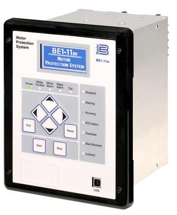
3 Motor Protection Application Guide 1. Introduction When applying protective relays to motors or any other equipment, the decision of how much protection is enough must be made. The answer depends on motor rewind cost, loss of production, effect of downtime, new versus old installation, metering, control, and the consequences of a motor failure on the electrical system and process. This guide presents an overview of motor hazards and a discussion of detection and protection options. Typical setting value ranges for the Basler Electric BE1-11m protection system are given along with considerations to help designers and users when selecting Basler's motor protection solution. Most of the protection functions apply to squirrel cage, wound, induction motors. Additional protection elements are needed for synchronous motors and are mentioned in this guide. 2. Overview of Motor Hazards Motor protection is a challenge because many different incidents can affect a motor and the associated load. Motor hazards include the following: Motor induced High internal temperature Insulation failure (faults within the motor) Bearing failure Mechanical failure Failure to start Synchronous motors - loss of field Load induced Overload and underload Jamming High inertia, especially at starting Environment induced High ambient temperature High contaminant level or blocked ventilation Extreme cold or wet conditions Source induced Loss of phase or phases Voltage unbalance Overvoltage Undervoltage Phase reversal Out-of-step condition resulting from system disturbance Operation induced Closing out of phase High duty cycle Jogging Rapid reversing 3.1 Stator Faults 3. Protection Phase Fault Overcurrent Protection: Choose the phase CT so the motor running mode full load amps (FLA) is no less than 50% of the rated phase CT primary. Ideally, the phase CT primary should be chosen so the FLA is 100% of the phase CT primary or slightly less, but never more. Phase-to-phase and three-phase stator faults usually are detected with nondirectional, instantaneous elements. If the available threephase fault current is a low multiple of the relay setting (weak system), quick pickup is not assured. In this situation, differential relaying should be considered (see Section 3.2). Otherwise, instantaneous phase overcurrent elements typically are applicable when the motor rating is less than one-half of the supply transformer kva rating. 1
4 When an instantaneous element is used for stator faults the setting should be as low as possible, yet never operate during the starting period. The locked rotor amps (LRA), I LR is usually six times the full load amps (FLA), I FL. Fig. 1 illustrates the element settings in relation to the starting current and the FLA. The instantaneous phase element (50P) should be set at no less than 1.7 times the LRA (using the value of LRA at maximum starting voltage), plus a safety margin (1.25 pu plus relay accuracy (0.02). This setting assumes the element is sensitive to the transient overreach (DC offset) of an asymmetrical fault. Lower settings are possible if the element disregards the transient component or if a time delay longer than the transient time (6-15 cycles) is added (50TP). Verify that the minimum available three-phase fault current at the motor terminals is at least 3 times the element setting. When applying a time delay ensure that all of the equipment can withstand the maximum available fault current for the total clearing time (element operation time, plus auxiliary time delay, plus circuit breaker operating its greater sensitivity. Differential protection is always preferred; however, it is generally more costly than instantaneous relaying because all six leads must be brought out of the motor and additional elements might be required. Differential protection is selected over other methods because of its sensitivity, speed and security. a) Self-balancing differential: The most economical approach is self-balancing differential as shown in Fig. 2. The cost for this method is reduced because only three CTs are required instead of the six CTs needed for larger motors with larger conductors. This differential requires one ring or doughnut CT per phase of sufficient diameter to accommodate conductors from both ends of the motor, as well as three 50 elements (one each per phase). This scheme is selfbalancing and produces no current for starting or load variation and, because there is only one CT per phase, there is no concern about matching CT performance to eliminate unequal CT saturation. CT saturation is likely for large fault currents but is sufficiently slow to allow the instantaneous elements to operate. time). FIGURE 1. STATOR SHORT-CIRCUIT PROTECTION WITH 50 OR 50P ELEMENT Differential Protection: Differential protection is used on motors where the available short-circuit current is close to the value of LRA. It is also used on very large motors because of FIGURE 2. SELF-BALANCING DIFFERENTIAL. 2
5 b) Percentage-restraint differential: An alternate form of differential protection uses six CTs, used especially on HP and greater motors (see Fig. 3). Not all motors are built with access to both ends of the motor windings; in which case this type of differential protection cannot be used. Order the external neutral connections to implement differential protection. Typically, all six CTs are the same ratio and accuracy class. When connecting the CTs, observe correct CT phasing as shown in Fig. 3. A motor relay with three, two-winding inputs can be applied. Ideally, equal currents flow in the restraint windings for normal load, starting and external faults. For internal phase or ground faults, all of the current will flow through the operate windings. The CTs do not always give the same secondary current for the same primary current because of variations in manufacturing and burden connections (meters, unequal lead lengths). For example, during a fault, non-identical error currents can flow because of dc offset so that the transient response in the CTs is not the same. The differential function must be set above the maximum error current that can flow during an external fault; yet the element must be set below the minimum fault current that can flow during a winding fault. Using the percentagedifferential relaying concept, the differential current required to operate the element is a percentage of the "through" or total restraint current. Modern motor relays often have separate settings for starting mode and running mode percentage differential slopes. The scheme also protects for cable faults between the motor and the motor breaker (52) by using the line-side CTs of the breaker. If the motor and motor breaker are supplied separately, match the CT ratios and accuracy classes when specifying the equipment. FIGURE 3. CONVENTIONAL PERCENTAGE-DIFFERENTIAL RELAYING Ground Fault Protection: a) Ground sensor 50G: Common causes of motor ground faults are damage to motor conductor insulation and internal shorts from moisture within the motor. The preferred and most sensitive method to detect stator ground faults is with a ground sensor CT. This scheme works particularly well with solidly grounded connections and also supplies good results in low-impedance grounded systems. See Fig. 4. All three-phase leads from the motor pass through the opening of a flux summation or toroidal current transformer supplying the instantaneous overcurrent 50G element shown in Fig. 4. This arrangement leaves only the groundfault zero-sequence currents in the CT. This CT has a maximum opening around 8 inches (20 cm) that prevents its use on larger motors. With a fixed ratio of 50:5 (regardless of the size of the motor) and a sensitive instantaneous overcurrent, the toroidal differential provides a pickup in the range of 4-12 amps. If more sensitive settings are required, add a time delay to avoid nuisance trips caused by zero-sequence cable capacitance current flow during external faults. The ground fault sensor connection might be the only scheme providing sufficient sensitivity when the supply system is high-impedance grounded. If a large ground fault current is available in a solidly grounded system, the 50G element must operate before the low-ratio CT saturates. Fortunately, the high impedance of modern relays reduces the CT burden and alleviates this problem. 3
6 b) Residual ground connection 51N: For larger motors where the conductors will not fit through a ground sensor CT, the residual ground connection shown in Fig. 4 must be used. The ground fault element sensitivity is limited by the phase CT ratio. Because unequal CT performance is expected, the built-in timing of a 51 element avoids tripping on false residual current. This 51N element must be coordinated against the 51G system ground protection element (typically in the supply transformer neutral, if used). Set the 51N delay with sufficient time to override any spurious ground current that might be caused by switching or other system transients. winding, proportional to I 2 t, is 9 to 49 times rated conditions and the winding is without benefit of the ventilation normally produced by motor rotation. Actual values of LRA are part of the motor data supplied by the motor manufacturer. Depending on the design, a motor can be thermally stator limited or rotor limited during locked-rotor conditions. The motor manufacturer can furnish the allowable locked-rotor time only after the motor design is completed. This time is given as time at rated locked-rotor current starting from either rated ambient temperature (cold stall time) or rated operating temperature (hot stall time). These parameters are given as part of the motor time-current curve defined by IEEE Standard 620. Starting times depend on motor design and load torque characteristics and must be determined for each application. Although starting times of 2 to 20 seconds are common, high-inertia loads might take several minutes to attain full speed. Starting time increases if bus voltage is less than nominal. The starting current of a motor falls between the locked rotor value and the FLA when the rotor begins to turn. Therefore, stator heating decreases as the motor accelerates. FIGURE 4. GROUND SENSOR ELEMENT (50G) AND RESIDUAL GROUND CONNECTION (51N AND 50N). c) Ground fault 50N: In a residually connected, solidly grounded feeder application, where the ground fault is usually high and the CT quality is good (C-400 or better), an instantaneous element (50N) can be used for ground-fault tripping. The system is solidly grounded so a ground fault will draw current in the magnitude of a three-phase fault, per IEEE Standard C An alternate method is to set this element at 4 times FLA or greater to avoid tripping on starting. 3.2 Thermal Damage When a motor stator winding is energized with the rotor at rest or "locked," stator winding currents can range from 3 to 7 times rated full-load value depending on motor design and supply system impedance. Heating in the stator The motor thermal limits curve has three separate pieces and is based on the three running conditions of the motor (see Fig. 5, upper curve): Locked rotor or stall condition Motor acceleration Motor running overload For most motors the motor thermal limit curve is one smooth curve. In most cases manufacturers provide curves for both hot and cold motor conditions. Overloads must be below this motor thermal damage curve. However, especially in long starting, high-inertia motors, the starting thermal damage curve can have similar current as does the running (overload) mode thermal curve; leading to possible nuisance trip during starting. In this case, the starting thermal damage curve (locked rotor and acceleration) and the running thermal damage curves do not fit smoothly together. Modern motor protection relays use custom locked rotor and running (overload) curves to fit motor protection to these type of motor thermal limits. 4
7 I eq = equivalent thermal current in pu (unit of thermal pickup current) I = maximum phase current in pu I 1 = positive sequence fundamental component of current in pu I 2 = negative-sequence fundamental component of current in pu k = constant to determine additional heating caused by negative-sequence current in pu FIGURE 5. MOTOR THERMAL CURVE LIMIT Thermal Overload Protection: The life of the motor is reduced if the winding temperatures exceed the designated insulation class levels for a significant time. Prolonged operation at 10 C above the design temperature limits reduces motor life by a factor of two. Motor thermal characteristics must be managed carefully. a) 49 thermal model: A 49 thermal element creates a realistic thermal model of the motor because the 49 thermal element takes the load level and negative-sequence current into account. Thus, the thermal model creates an "equivalent current" I eq that best represents the actual motor dynamics. In particular, the thermal model calculation uses equivalent thermal current with unbalance biasing, the selected thermal curve, pickup current, motor cooling constant(s), RTD biasing based upon measured stator temperature, and the hot/cold safe stall ratio. The equivalent thermal current, I eq follows: I eq = I 1+k I 2 I 1 2 where, Formula 1 The factor k is a user setting. With k set to 8, the formula gives a derating factor closely matched to the NEMA MG (Motor Guide) derating factor (from voltage unbalance). A larger k makes the estimation of equivalent current, I eq more conservative. If k is set to 0, the motor relay uses maximum positive-sequence current only (I 1 max). Because voltage sensing is optional, the unbalance ratio of negative-sequence to positivesequence current (I 2 /I 1 ) is used instead of voltage unbalance. The Basler thermal model implementation has two unique features. One is the ability to tailor the 49 thermal model pickup with the Overload (OL) setting. The range of this setting is The normal thermal curve pickup is at service factor (SF) FLA; with this setting the thermal curve pickup becomes OL SF FLA. Using this Overload setting, the thermal model pickup can be fine tuned for lightly or heavily loaded applications. Another unique feature is the ability to set the thermal capacity at which the motor will perform an emergency start. This setting, Max Emergency Thermal Capacity, increases the trip point of the thermal model, thus keeping the process running. Once the emergency start is made, the thermal model adjusts to retain thermal data and thus protects the motor as the motor cools into the nominal thermal range. Most relay manufacturers do not provide this important protection. b) RTD temperature biasing: RTD biasing modifies the thermal model by taking temperature data from the stator RTDs as additional inputs to the thermal capacity calculations. RTD biasing accounts for motor operation in high ambient temperatures or after experiencing a cooling loss. 5
8 Typically, three points are defined at Minimum RTD Bias Temperature, Center RTD Bias Temperature, and Maximum RTD Bias Temperature. Set the Minimum RTD Bias at ambient (40 C). A good starting point for the centerpoint Thermal Capacity (%TC) is the percentage difference between Hot Stall time and Cold Stall time. Later, this point can be modified from a learned observation and from motor monitoring. Determine centerpoint temperature from manufacturer's data: Temperature Rise of Stator times 10 percent margin plus the rated operation Ambient Temperature. Set the third and end point for maximum insulation temperature. For example, if maximum insulation factor of the motor is F (most used), then 155 C and 100% TC is the end point of RTD biasing. More than three points for RTD biasing can be set resulting in more motor productivity in high-temperature environments. Because thermal biasing is an exponential temperature phenomenon, the Basler BE1-11m provides more than three points for more accurate biasing. c) RTD temperature sensing and voting: Motor relays monitor the RTD temperature data, usually six embedded in the stator windings (two per phase) and one or two on the motor bearings. The motor relay uses RTD voting to force concurrence among the different blocks of RTD data. For example, if stator RTD voting is set for 3, then 3 or more temperatures must exceed the pickup level before the relay takes action. With this setting, two RTDs can be malfunctioning and the motor relay continues to use correct temperature data. Typically, the motor relay accepts two setting levels for each monitored point: a low setting for alarm and a high setting for shutdown. The specific settings are derived from the winding insulation class, defined in NEMA MG1, and judgment based on the plant operating conditions. The recommended setting for alarm temperature level is the sum of the maximum ambient, plus 10 degrees hot spot allowance, plus the full-load temperature rise. This value should be below the insulation class rating. The trip level should be at the insulation class temperature; however, this setting can be as much as 50 C above the class rating if the process is critical because the loss of life from occasional short overload periods is insignificant. Setting the trip temperature at the insulation class limit is a conservative setting. Typically, motors are cooled by a rotormounted fan blade that forces air through the motor frame while the motor is running. Thermal limits and temperature rise are based on this cooling functioning as designed with a known level of ambient air temperature. If normal cooling is blocked, overheating at normal load current is possible. The only protection will be temperature-measuring devices located in the motor such as RTDs or thermocouples. The motor relay provides this protection with inputs from RTDs imbedded in one or more of the winding slots. With the Basler BE1-11m, thermocouples placed in the air plenum can be connected to 4-20 ma or 0-10 V transducer modules as inputs to the Remote Module (the Remote Module accepts both RTDs and analog inputs). d) Traditional 51-element implentation: Older motor protection used 51 elements instead of the 49 thermal model and no RTD temperature data. Fig. 6 compares these two methods of motor protection, IEEE device numbers (51 or 49). These devices might have nearly identical static characteristics but differ greatly in their dynamic response; therefore, in their ability to track the motor temperature over time. FIGURE 6. THERMAL OVERLOAD - RUNNING. 6
9 To force the static characteristic to pass through point P in Fig. 6, the time dial in a 51 element or the time constant in the 49 thermal element is adjusted. The dynamic response of a 51 element is linear and uses uncompensated motor current, whereas the 49 thermal model has an exponential response and uses the equivalent current, I eq. Running mode thermal overload can be provided by an overcurrent element 51P that has a time-current characteristic similar to the thermal overload limit. The minimum pick up of this 51P element is the continuous overload specification of the motor, i.e., FLA SF. The characteristic is usually an I 2 t curve. The time dial is chosen to coordinate against the thermal limit (Point P) and allow short duration overloads predictable from the process analysis. Fig. 7 compares the 51 element and the 49 thermal model response for motor current step changes. The 49 thermal model element performs better, especially when the process requires tolerating temporary overloads. The 49 thermal mode element "remembers" the work (heat) in the motor; the 49 element does not reset to zero when the current is below the overload limit as does the 51 element (see the 2400 second area). Instead, the 49 thermal model element settles at a value corresponding to the thermal capacity (TC) at the given load level. The 51 element tends to trip faster than the 49 thermal model and complete motor usage is not attained. With the 49 thermal model element, more work is obtained from the motor without damage (see the 6400 second area). However, the 51 element can serve as a backup to the 49 thermal element. The 49 thermal model gives a more accurate presentation of motor operation and heating Locked Rotor Protection: The motor relay thermal model provides locked rotor protection because of the rapid heating that occurs in a motor that does not transition from starting mode to running mode in sufficient time (acceleration too long). Backup to the thermal model is shown as a 14 speed switch input (see Fig. 8). The speed switch is set at 10%-50% of full speed. Use a timer with the speed switch so that the motor trips if shaft rotation does not reach set rotational speed within the starting period. FIGURE 8. LOCKED ROTOR PROTECTION. FIGURE 7. COMPARE 49 THERMAL MODEL ELEMENT AND 51L DYNAMIC RESPONSE. Failure to accelerate to running mode can also be protected by using the 48 element. This element is a timer that starts when a motor starts and trips if the timer setting is exceeded prior to the motor reaching the running mode. Motor start and motor run signals are provided to the element. The 48 time setting must be set to a time a little longer (2-5 seconds) than the typical start time of the motor and no longer the maximum hot stall time. 7
10 The 51P element is a time-overcurrent element set for backup of the running mode thermal overload. Primary protection is from the thermal model. The failure to accelerate is detected by the thermal model, with backup from the overload 51P element (set for running mode) shown in Fig. 8, as well as 14 and 48 elements. For some large induction motors with low starting voltages or with high-inertia loads and long starting times, the starting time can exceed the allowable locked-rotor time without excessively heating the rotor. Make initial settings for the thermal model and backup elements, if used, then examine motor start reports and learned starting parameters to optimize locked rotor protection. The 48 element and the 14 speed switch are particularly helpful for highinertia (long) starts. For high inertia, prolonged starting, set the 48 incomplete sequence element to a time slightly longer than the actual start time; the thermal model will recognize that the motor shaft is turning and starting current is dropping. Because the motor shaft is turning there is motor cooling. Another method is to use a 14 speed switch. The speed switch trips a motor start effort if no or insufficient shaft turning has occurred within a preset time delay Repetitive Starts and Jogging Protection: In repeated starting and intermittent operation, very little heat is removed by the cooling medium produced by a turning rotor. Repeated starts can build temperatures to dangerously high values in either stator or rotor windings unless sufficient time is provided to allow the heat to dissipate. The NEMA MG1 Sections 12.54, 20.12, and provide guidelines for typical installations. These standards allow two starts in succession, coasting to reset between starts with the motor initially at ambient temperature, and for one start when the motor is at a temperature not exceeding its rated load operating temperature. This best practice assumes that the applied voltage, frequency, load torque during acceleration, method of starting, and load inertia are all within motor design. The application and protection of motors having abnormal starting conditions must be coordinated with the data from the manufacturer. The motor relay uses manufacturer's data such as hot cold stall time and the cooling time constants to the 49 thermal model to help limit excessive starting. Modern motor relays include a protective element for thermal overload protection. Unlike an inverse-time electromechanical counterpart, this relay tracks the stored value of the "thermal capacity". Motor starting alone can use 50%-65% of the available thermal capacity. The thermal-model motor relay also recognizes that a stopped motor cools more slowly than a running motor because there is no cooling air produced by the rotor. Therefore, it is possible that attempting to start a motor twice in rapid succession might cause a protective trip on thermal overload. Although provision is made for emergency starting (to continue or save a valuable process), the manufacturer's recommendation for frequent starts should be used. The motor relay also provides Starts Per Time Interval, Time Between Starts, Time Since Last Start, and Time Since Last Trip. Select a setting for number of starts and time to match manufacturer recommendations. Exact determination of starting occurrences is a very complex calculation that is affected by many factors including motor size, enclosure, voltage, ambient temperature, inertia, load-speed-torque characteristic, and running time. Typically, motor restarts depend more on the stator thermal capacity than on rotor thermal capacity and stall time. The best rule, by far, is to minimize the number of starts because each start reduces the life of the motor Unbalance Protection: a) Cause and effects: Unbalance in the feeder phase voltages or motor winding impedance causes unbalanced currents to flow to the motor. These currents can cause more damage than symmetrical faults or balanced three-phase starting or running abnormalities. The negative-sequence current I 2 from the unbalance causes rotor heating and additional copper losses in the stator windings because of increased line current flow at 120 Hz. The resulting I 2 R loss raises the motor temperature quickly. Rotor structural damage is common when the protective relaying does not operate quickly for unbalanced conditions. b) Detection: The low negative-sequence motor impedance causes the amount of negative-sequence current to be typically about five times larger than the amount of negativesequence voltage. Also, the negative-sequence 8
11 voltage (V2) measurement yields very different results depending on the location. Although the current unbalance is the parameter directly responsible for the temperature increase in the motor, two detection methods are available: voltage and current unbalance. Two common measuring techniques have been implemented: NEMA defined unbalance Negative-sequence measurement The NEMA definition, found in MG1 Section is percent voltage unbalance = 100 (maximum voltage deviation from average voltage) / average voltage Voltage Sensing (47) or Phase Reversal: Voltage sensing element 47 can be connected to a bus or at the motor. In present usage, this protection commonly detects gross wiring errors like a phase reversal or an open phase. Connecting a 47 element to a bus on which many motors have connection has the advantage of detecting the unbalance voltage for a complete set of motors, but has the disadvantage of tripping all motors when an unbalance occurs. Slight bus voltage unbalance can be tolerated by a motor if its load is lighter at the time of the unbalance Voltage Unbalance Element: a) Motor terminal application: Voltage unbalance 47 protection can be applied at the motor terminals or at the motor bus (preferred). NEMA MG and recommend that continuous voltage unbalance should never exceed 5%. For small to moderate unbalance, the NEMA and negative-sequence formula yield approximately the same result. If used, a voltage unbalance element can be set at a maximum pickup of 5%. To set the time delay to trip, consider the thermal damage by the corresponding negative-sequence current. This voltage unbalance of 5% corresponds to an I 2 of about 25%, provided the voltage is measured at the motor terminals. Assuming the motor can tolerate I 2 t = t un, the maximum time delay for a 5% voltage unbalance and t un = 40 would be 640 seconds. Although no standard exists for motors, a value of t un = 40 is often used. characteristic (the Basler BE1-11m can perform voltage inverse-time curves and is a unique exception). If the timing curve is inverse, the time dial should be selected to cause tripping when the voltage unbalance at the motor terminals, corresponding to the 1 pu I 2, is equal to 20%. Base the time delay on the worst case expected unbalance, i.e. open phase in the motor feeder cable. The positive and negativesequence currents are then equal (1pu at full load). The trip time for this unbalance condition would thus be equal to t un (I 2 =1pu). For t un = 40, the maximum delay for an open phase should be 40 seconds. If the element uses a definite time, this point needs to be the setting and result in overprotection, if the unbalance is less severe. b) Motor bus application: In most applications, the voltage seen by the 47N will not come from the motor terminal, but from the bus. Depending on the size and nature of other loads connected to the bus, the 47N might not sense the open phase in the motor feeder. Therefore, 47N application requires careful consideration, as well as backup from current-based protection 46. This situation is the reason voltage-based unbalance protection has become a phase-reversal or phase-loss protection with high settings (50%) Current Unbalance: Current unbalance (46) is measured in the motor feeder itself and has the advantage of being applied at each motor. It is easy to implement in multifunction motor relays like the BE1-11m. Measuring algorithms include the true negative-sequence measurement and the difference between the maximum and minimum phase currents. To relate the current unbalance setting to the 5% NEMA voltage unbalance limit, it is necessary to establish the correlation between the current unbalance algorithm and the unbalanced voltage. For a negativesequence type element, the I 2 percent setting is approximately 4 to 5 times the percent voltage unbalance for the worst case nominal load condition. Most motor protection relays do not offer the 47N element with an extremely inverse characteristic that could emulate the I 2 t 9
12 FIGURE 9. THE EFFECTS OF VOLTAGE AND FREQUENCY VARIATION ON INDUCTION-MOTOR CHARACTERISTICS. The current unbalance measuring elements have an I 22 t = k characteristic that makes the time delay settings easier to apply than with the voltage element. If no other information is available, choose k = 40. The worst-case unbalance occurs for an open phase at full load. The negative-sequence current is then equal to the positive sequence current, i.e. 1 pu. The time dial should be set to cause tripping in 40 seconds in this case where k = 40. For current unbalances it is common to provide an alarm first so that corrective action can be taken before removing the motor from service. This element is an inverse-time overcurrent element (51) using negativesequence as the operating quantity. The curve characteristic should be a straight line on log-log scales, emulating the I 2 t = k, and should be set to match the motor running mode characteristic. The Basler BE1-11m has many current elements and thus can provide multiple timing and alarm levels. 3.3 Abnormal Supply According to the NEMA MG1, Part , motors are expected generally to operate successfully under running conditions at rated load with a variation of plus or minus 10% of rated voltage, plus or minus 5% of rated frequency, or a combination of the two, provided the sum of the absolute values of the deviations does not exceed 10% and the frequency variation does not exceed plus or minus 5%. For synchronous motors, rated excitation current must be maintained. Fig. 9 shows the effects of voltage and frequency variations on induction motor characteristics. Given these limits, there is no single protective device that can make a direct determination of these quantities simultaneously. However, variations in voltage or frequency will result usually in an increase in stator winding temperature over a long period. The 49 thermal model as well as direct temperature measuring devices, such as RTDs, will detect these changes 10
13 and provide warning or tripping, provided the abnormal condition is not extreme. Voltage and current elements provide abnormal supply protection for extreme cases. A large induction motor rotating at rated speed or a large synchronous motor with fixed excitation can be approximated at steadystate conditions as a constant kilovoltampere device for a given shaft load; therefore, current variations follow voltage variations inversely. An undervoltage condition will result in an overcurrent condition. Single-phase overor undervoltage is likely to be detected by unbalanced voltage or current protection if so equipped. Three-phase undervoltage is protected by thermal overload protection because the current will be greater than normal for a given load. Voltage elements, as previously mentioned, are not always sufficiently selective to provide reliable protection, especially on buses where several motors are connected because the spinning motors will support the voltage on the low or missing phase. However, an inverse time or definite time undervoltage (27) element, active only in the running mode, is recommended to trip when a prolonged undervoltage condition exists and as a backup. Pickup settings of 0.85 per unit will provide adequate protection. The time delay should be set to ignore transient voltage dips (100 ms). A separate concern of undervoltage is its impact on starting a motor. Unlike a running motor, low voltage on starting of a motor produces lower starting current and, hence, lowers torque. If the torque is too low to overcome the torque requirements of the load, the motor will not start successfully. The motor relay uses an undervoltage element 27 to check the supply voltage before starting, active only in starting. If the voltage is too low the element prevents starting. Pickup settings of 0.7 per unit will provide adequate protection with no time delay Loss-of-Potential Element: Having accurate potential readings at the motor relay is necessary to determine whether a voltage unbalance condition is actual or is the cause of a blown sensing fuse. Losing a sensing fuse can cause a motor to trip offline if the motor relay does not have fuse loss protection, a 60FL element, to block unwanted tripping. The 60FL element detects fuse loss and loss of potential by using voltage and current thresholds that are expressed as a percentage of the nominal voltage and current values. Upon detection of a fuse loss condition, 60FL will block voltage elements selected by the user such as 27/59 positive-, negative- and zero-sequence elements. The 60FL element also provides an alarm that can be mapped as a Major or Minor alarm for immediate maintenance inspection. If the voltage elements are not blocked and are allowed to falsely trip the protected motor, serious "process" consequences may result. Modern motor protection relays like the Basler BE1-11m offer this protection Voltage Drop During Starting: Another concern during motor starting is the voltage drop caused by the LRA flowing through the supply transformer, especially for across-the-line (ATL) starts. A weak system or undersized supply transformer worsens the situation. When the supply voltage decreases during start, then so do the current and starting torque. If there are other running motors on the bus, the reduced voltage causes greater currents and further increases the voltage drop. Should the voltage drop sufficiently low it is possible for the motor torque to be too low and prevent a successful motor start. Whether motor starting or system weakness is the problem, reduced voltage can cause trouble at times other than during acceleration. Reduced voltage in running mode will cause overheating with time. Short-term voltage dips might cause an already running motor to stall. The effect of trying to start more than one motor at the same time should be considered since it will increase the undervoltage condition. Many motors use motor contactors powered by the ac line voltage. Reduced voltage could drop out the motor contactor and cause an already running motor to drop off line when the motor contactor drops out. The Basler BE1-11m provides custom curves with voltage dependency to accommodate lowered-voltage starting. To avoid these problems, perform voltagedrop calculations to determine the motor voltage conditions during starting. Check the calculations at maximum and minimum expected bus voltage before start. In a properly designed 11
14 power system, with a good match between bus and motor design voltages, starting voltage dips of 15% are common. Designers frequently assume that an accelerating motor draws its full voltage inrush current and calculate the upstream voltage drops on that basis. Clearly, any voltage drop in the supply system means that full voltage and corresponding inrush current cannot be present Overvoltage: Overvoltage conditions can stress the motor winding insulation and decrease motor life. Induction motors experience a slight increase in efficiency when the motor is running in an overvoltage condition. Motor slip decreases and is inversely proportional to the square of the voltage. The current decreases as well as the power factor. Because of I 2 t, temperature also decreases. However, most new motor designs are close to the flux saturation point; thus increasing the voltage increases the V/Hz ratio and could cause air gap flux saturation resulting in excess motor heating. The motor relay thermal element detects this heating and eventually trips the motor. Faster reaction comes from setting an overvoltage element (59). Referencing NEMA MG1 Part 14.33, set the overvoltage element to alarm at 10% greater than nominal voltage. Set the time delay for 100 ms to avoid nuisance alarms Reduced-Voltage Starting: Employ reduced-voltage starting techniques when voltage drops are excessive during starting. These add to the motor controls but might be less expensive than increasing transformer and cable sizing. All of these techniques use some method to apply partial voltage to the motor during the initial starting sequence, then when the motor is at partial speed, full voltage is applied to finish the start sequence. Modern motor relays support reduced-voltage starting. Use different settings groups to optimize protection for each operation mode. Wye-Delta starting applies a reduced voltage at the beginning of the start sequence with a wye connection of the motor and then changes to the delta connection for the motor to complete the start sequence. This arrangement reduces starting torque and voltage drop on the motor bus. Another method of reduced voltage starting is autotransformer start. The autotransformer is connected in wye with the supply voltage and the tapped partial voltage is applied to the motor during starting mode. When the starting contactor makes its transition, the partial voltage source is opened and full supply voltage is applied Frequency Protection: Frequency in excess of 5% over the rated frequency without a corresponding voltage increase is not considered to be a hazardous condition for synchronous or induction motors provided the driven equipment does not overload the motors at the greater frequency. At decreased frequency without a corresponding voltage drop, the flux requirements of a motor are increased, thus increasing the hysteresis and eddy current losses and heating. Sustained operation at 5% below nominal frequency and rated or overvoltage is not permissible per NEMA MG1, Part Protection against this type of operation can be thermal overload or RTD temperature measurement. In addition, more refined protection can be obtained with the 81 underfrequency elements in fully featured motor relays. Time delay settings of seconds allow the motor to ride though transient conditions without nuisance tripping. Many utility substations are equipped with underfrequency (UF) load shedding relays to reduce the system load during a loss of generation and subsequent decay in system frequency. Large motor loads connected to the distribution substation might interfere with the normal operation of the underfrequency relay by showing a decline in frequency without a complete loss of voltage. This situation can happen when the distribution bus is disconnected from the supply transformer and the underfrequency (UF) relay(s) is connected to the distribution bus. The UF relay then sees the residual voltage from the motor load and might operate incorrectly. Relocating the underfrequency voltage transformer to the high side of the supply transformer or adding additional time delay to the underfrequency time delay usually solves the problem. 12
15 3.4 Mechanical or Process Protection Generally, we think of protective relays as devices that protect electrical equipment (motors, breakers, etc.). However, in the case of motor protection there are times when it is more important to protect the process Undercurrent (37) (Loss of Load): Some pump motors use the pumped fluid for cooling and a sudden loss of current indicates an immediate cooling loss, causing process disruption and possible motor damage. For example, a water pumping station operates continuously at 90% of FLA. If the pump is damaged, lost its prime, or the shaft broke, the load on the motor is drastically reduced. In this case an undercurrent element (37) is valuable. This element is not in service until the motor is in running mode and set to detect loss-of-load conditions to alarm or trip from 50%-70% of FLA. Set a time delay to ride through temporary supply fluctuations (100 ms) Underpower Protection (32): The underpower protection element can be set to be more sensitive than the 37 undercurrent element for process-related loss of load problems Jam Protection: Motor process such as chippers and shredders can become jammed. The motor relay enables jam protection in running mode only. This protection detects stalls when the load torque exceeds the breakdown torque and causes its speed to decrease to zero or near zero. This situation occurs when the applied shaft load is greater than the producing motor torque. This condition will develop motor current equal to or approaching lockedrotor current, and some reduction in terminal voltage depending upon the motor impedance. According to NEMA MG1, the maximum stall time must be marked on the motor name plate. Set jam protection with an instantaneous overcurrent element (50) at 70% of LRA. Time delay at this current should be instantaneous Bearing Protection: To minimize damage caused by bearing failure, protective devices can sound an alarm or de-energize the motor. Bearing protective devices respond to one or more of the following conditions: (1) Low oil level in reservoir: (71) level switch (2) Low oil pressure: (63) pressure switch (3) Reduced oil flow: (80) flow switch (4) High temperature: (38) thermocouples (5) Rate of temperature rise (6) Vibration (used on motors with anti-friction bearings in place of thermal devices) Usually, resistance temperature detectors (RTDs) monitor large motor bearings and are used as one of the inputs to the motor relay. Dual-set points of the RTD function allows for alarm and trip settings at two different temperatures. Unlike many motor relays, the Basler BE1-11m motor relay includes 4-20 ma or 0-10 Vdc analog transducer inputs in the Remote Modules to bring these signals and other process transducers back to the motor relay. In this manner the motor relay directs and modifies the production process, acting to replace a PLC (programmable logic controller). 4. Bus Transfer and Reclosing Many motor buses are critical to process or plant operation; therefore, they must be maintained if at all possible. For static loads, high-speed reclosing or transfer to an alternate source is appropriate. However, motor loads require special considerations. When the motor is disconnected from the voltage supply, the voltage at the motor terminals does not go to zero. The machine generates a voltage at its open-circuited terminals that decays with time. A fast reclose applies the full bus supply voltage in series with the residual motor voltage, producing a total winding voltage that can be dangerously high. Capacitors in the circuit make the situation worse because capacitors support the voltage level. A second complication is the decay in motor speed with respect to the supply system. The frequency of the residual voltage in the motor will be a decaying frequency value as the motor begins to slow. The worst case could be a nearly 2.0 per unit voltage and 180 out-of-phase condition with the supply voltage. The possibility of damage exists for local reclosing of the motor, high-side reclosing from the utility, transferring to an alternate source, or reduced-voltage motor starting. A Basler BE1-11 protection system with 13
16 sync-check capability or the BE1-700V relay can be utilized for this application. The safest restart method is with motor re-energization after some dead time, but other considerations apply. 4.1 Parallel Transfer Parallel transfer is a method of transferring process loads from one source to an alternate source. In this method, the bus-tie breaker is closed before the normal source breaker is opened. This method has gained wide acceptance because the transient on the motor bus is eliminated, assuming the two sources are in phase. However, the bus system designed for this transfer method might violate the interrupt rating for the circuit breakers and the short-term withstand ratings of the normal and alternate source power transformers. A fault in a motor or its leads occurring during the time the sources are paralleled might produce fault current levels in excess of the circuit breaker ratings. The probability of this happening is small; however, the consequences of such a fault should be thoroughly understood before the parallel transfer system is used. Parallel transfer requires a high-speed synchronization 25 element. Basler provides this 25 element in most styles of the BE1-11 protection system and the BE1-700V relay (see Fig. 10). This 25 element can detect that the phase difference across the bus tie breaker is within acceptable limits prior to transfer. Without this permission a large phase angle would cause a power surge through the bus system that could cause damage to the bus system components. An angle setting of degrees with no time delay should be used. 4.2 Fast Transfer Fast transfer involves opening the normal source breaker prior to closing the tie breaker, thus avoiding the problems associated with parallel transfer. This method minimizes the transfer time between sources. However, the bus must always be completely disconnected from both sources for a short period of time. One technique involves issuing simultaneous trip and close commands to the normal source and bus tie breaker. If the tripping breaker is abnormally slow, the sources can be briefly paralleled, introducing the problems of parallel transfer. Another method involves using a "52b" contact from the normal source breaker to close the bus tie breaker. Especially during abnormal transient conditions, supervision of the fast transfer requires a high-speed sync-check element found in most styles of the BE1-11 protection system and the BE1-700V relay. The sync-check ensures that the phase angle between the motor bus voltage and the alternate source voltage is within acceptable limits prior to closing the bus tie breaker. An angle setting of 15%-25% with no time delay should be used. 4.3 Delayed Transfer on Residual Voltage Residual voltage transfer involves waiting until the bus voltage drops below a predetermined point before closing the alternate source breaker. This technique is the slowest of the bus transfer methods in that the open-circuit time of the bus is the greatest. By waiting until the voltage is 33% of rated voltage, the resultant voltage across the alternate source breaker is reduced to a maximum of 1.33 p.u. This supervision can be achieved with a 27 element set at 0.33 per unit with no time delay or by adding a fixed time delay to the alternate source closure. Typical residual voltage decay is shown in Fig. 11. The length of time required for the voltage to decay depends on how quickly the stored electromechanical energy dissipates. The motor open-circuit time constant is defined as follows: FIGURE 10. HIGH-SPEED SYNCHRONIZATION CHECK. tc open = X m + X 2R / 2ΩfR 2R Formula 2 14
Motor Protection Application Considerations
 Motor Protection Application Considerations About the Authors Paul Lerley has 28 years of utility and electronics experience, including 15 years at Central Maine Power Co. He is a graduate of the University
This webinar brought to you by the Relion product family Advanced protection and control IEDs from ABB
 This webinar brought to you by the Relion product family Advanced protection and control IEDs from ABB Relion. Thinking beyond the box. Designed to seamlessly consolidate functions, Relion relays are smarter,
Motor Protection Fundamentals. Motor Protection - Agenda
 Motor Protection Fundamentals IEEE SF Power and Energy Society May 29, 2015 Ali Kazemi, PE Regional Technical Manager Schweitzer Engineering Laboratories Irvine, CA Copyright SEL 2015 Motor Protection
Unit Protection System for Pumped-Storage Power Stations
 Unit Protection System for Pumped-Storage Power Stations 1. Introduction In many power systems, pumped-storage power stations are used in addition to run-of-river power stations. These power stations serve
825-P Modular Protection System for motors Specification Guide
 Specification Guide 1.0 General 1.01 The motor protection relay shall have a current operating range of 0.5 and 5000 amperes. 1.02 The motor protection relay shall provide current measurement-based protection
CHAPTER 3 CAUSES AND EFFECTS OF ELECTRICAL FAULTS
 22 CHAPTER 3 CAUSES AND EFFECTS OF ELECTRICAL FAULTS 3.1 INTRODUCTION A large number of asynchronous motors are used in industrial processes even in sensitive applications. Consequently, a defect can induce
L. Photo. Figure 2: Types CA-16 Relay (rear view) Photo. Figure 1: Types CA-16 Relay (front view)
 Photo. Figure 1: Types CA-16 Relay (front view)") Figure 1: Types CA-16 Relay (front view) Photo Figure 2: Types CA-16 Relay (rear view) Photo 2 Sub 5 185A419 Sub 6 185A443 Figure 3: Internal Schematic of the Type CA-16 bus Relay or CA-26 Transformer
Figure 1: Types CA-16 Relay (front view) Photo Figure 2: Types CA-16 Relay (rear view) Photo 2 Sub 5 185A419 Sub 6 185A443 Figure 3: Internal Schematic of the Type CA-16 bus Relay or CA-26 Transformer
SHORT-STOP. Electronic Motor Brake Type G. Instructions and Setup Manual
 Electronic Motor Brake Type G Instructions and Setup Manual Table of Contents Table of Contents Electronic Motor Brake Type G... 1 1. INTRODUCTION... 2 2. DESCRIPTION AND APPLICATIONS... 2 3. SAFETY NOTES...
KD LV Motor Protection Relay
 1. Protection Features KD LV Motor Protection Relay Overload (for both cyclic and sustained overload conditions) Locked rotor by vectorial stall Running stall / jam Single phasing / Unbalance Earth leakage
Types of Motor Starters There are several types of motor starters. However, the two most basic types of these electrical devices are:
 Introduction Motor starters are one of the major inventions for motor control applications. As the name suggests, a starter is an electrical device which controls the electrical power for starting a motor.
34 th Hands-On Relay School
 34 th Hands-On Relay School Generation Track Overview Lecture Generator Design, Connections, and Grounding 1 Generator Main Components Stator Core lamination Winding Rotor Shaft Poles Slip rings Stator
Variable Frequency Drive Basics
 Variable Frequency Drive Basics Contact us Today for a FREE quotation to deliver this course at your company?s location. https://www.electricityforum.com/onsite-training-rfq Variable Frequency Drives are
Installation and Maintenance Instructions. World Leader in Modular Torque Limiters. PTM-4 Load Monitor
 World Leader in Modular Torque Limiters Installation and Maintenance Instructions PTM-4 Load Monitor 1304 Twin Oaks Street Wichita Falls, Texas 76302 (940) 723-7800 Fax: (940) 723-7888 E-mail: sales@brunelcorp.com
Motor Protection. Voltage Unbalance & Single-Phasing
 For Summary of Suggestions to Protect Three-Phase Motors Against Single-Phasing see the end of this section, page 137. Historically, the causes of motor failure can be attributed to: Overloads 30% Contaminants
Dual Power. Protection. Protection
 54 Fault Clearing Systems by Damien Tholomier., AREVA T&D Automation, Canada Dual Power Single Battery What if it? Short circuits and other abnormal power system conditions are very rear, but may result
RVS-AX Instruction Manual
 RVS-AX Analog Soft Starter 8-170A, 220-600V Instruction Manual Ver. 10/11/2009 2 Table of Content RVS-AX Instruction Manual 1. TABLE OF CONTENT 1. Table of Content...2 2. Safety & Warnings...3 2.1 Safety...3
Shunt Capacitor Bank Protection in UHV Pilot Project. Qing Tian
 Shunt Capacitor Bank Protection in UHV Pilot Project Qing Tian 2012-5 INTRODUCTION State Grid Corp. of China, the largest electric power provider in the country, has first build a 1000 kv transmission
MAGNETIC MOTOR STARTERS
 Chapter 6 MAGNETIC MOTOR STARTERS 1 The basic use for the magnetic contactor is for switching power in resistance heating elements, lighting, magnetic brakes, or heavy industrial solenoids. Contactors
This webinar brought to you by the Relion product family Advanced protection and control IEDs from ABB
 This webinar brought to you by the Relion product family Advanced protection and control IEDs from ABB Relion. Thinking beyond the box. Designed to seamlessly consolidate functions, Relion relays are smarter,
Direct On Line (DOL) Motor Starter. Direct Online Motor Starter
 Motor Starter. Direct Online Motor Starter") Direct On Line (DOL) Motor Starter Direct Online Motor Starter Different starting methods are employed for starting induction motors because Induction Motor draws more starting current during starting.
Direct On Line (DOL) Motor Starter Direct Online Motor Starter Different starting methods are employed for starting induction motors because Induction Motor draws more starting current during starting.
2.0 CONSTRUCTION AND OPERATION 3.0 CHARACTERISTICS K. CO (HI-LO) Overcurrent Relay
 Overcurrent Relay") 41-100K 2.0 CONSTRUCTION AND OPERATION The type CO relays consist of an overcurrent unit (CO), either an Indicating Switch (ICS) or an ac Auxiliary Switch (ACS) and an Indicating Instantaneous Trip unit
41-100K 2.0 CONSTRUCTION AND OPERATION The type CO relays consist of an overcurrent unit (CO), either an Indicating Switch (ICS) or an ac Auxiliary Switch (ACS) and an Indicating Instantaneous Trip unit
Pretest Module 21 Units 1-4 AC Generators & Three-Phase Motors
 Pretest Module 21 Units 1-4 AC Generators & Three-Phase Motors 1. What are the two main parts of a three-phase motor? Stator and Rotor 2. Which part of a three-phase squirrel-cage induction motor is a
Application Note: Protection of Medium-Power Motors With SIPROTEC Compact 7SK80
 Application Note: Protection of Medium-Power Motors With SIPROTEC Compact 7SK80 Motor settings using the SIPROTEC Compact motor protection relay 7SK80 is explained below. Information is given on how to
C. Figure 1. CA-16 Front View Figure 2. CA-16 Rear View
 Figure 1. CA-16 Front View Figure 2. CA-16 Rear View 2 2.1. Restraint Elements Each restraint element consists of an E laminated electromagnet with two primary coils and a secondary coil on its center
AIR COOLED RECTIFIER SPECIFICATION S-50-A
 SPECIFICATIONS AIR COOLED RECTIFIER Spec50a1 5JAN1999 SPECIFICATION S-50-A HIGH VOLTAGE SINGLE TRANSFORMER AIR COOLED RECTIFIER Standard output power range: 250 to 600 volts at 100 to 1,200 amperes TECHNICAL
The University of New South Wales. School of Electrical Engineering and Telecommunications. Industrial and Commercial Power Systems Topic 6
 The University of New South Wales School of Electrical Engineering and Telecommunications Industrial and Commercial Power Systems Topic 6 PROTECTIONS 1 FUNCTION OF ELECTRICAL PROTECTION SYSTEMS Problems:
3.2. Current Limiting Fuses. Contents
 .2 Contents Description Current Limiting Applications................. Voltage Rating.......................... Interrupting Rating....................... Continuous Current Rating................ Fuse
Experiences in a Motor Protection Retrofit
 Special Feature by Kyle Craig, Ontario Power Generation Amy Sinclair, Schweitzer Engineering Laboratories, Inc. Experiences in a Motor Protection Retrofit Introduction The initial stage of any project
Pretest Module 21 Units 1-3 AC Generators & Three-Phase Motors
 Pretest Module 21 Units 1-3 AC Generators & Three-Phase Motors 1. What are the two main parts of a three-phase 2. Which part of a three-phase squirrel-cage induction motor is a hollow core? 3. What are
Principles of iers (intelligent
 Principles of iers (intelligent Energy Recovery System) Chapter 4 Table of Contents............... 4 1 Principles of the iers....................................... 4 2 Enabling Intelligent Energy Recovery
Functional Overview and Operating Principles for the AR-OH and AR360 Overhead AutoRANGER Fault Indicators
 WHITE PAPER Functional Overview and Operating Principles for the AR-OH and AR360 Overhead AutoRANGER Fault Indicators Tyson Salewske and Anthony Patenaude INTRODUCTION The purpose of this document is to
Código de rotor bloqueado Rotor bloqueado, Letra de código. Rotor bloqueado, Letra de código
 Letra de código Código de rotor bloqueado Rotor bloqueado, Letra de código kva / hp kva / hp A 0.00 3.15 L 9.00 10.00 B 3.15 3.55 M 10.00 11.00 C 3.55 4.00 N 11.00 12.50 D 4.00 4.50 P 12.50 14.00 E 4.50
AGN Unbalanced Loads
 Application Guidance Notes: Technical Information from Cummins Generator Technologies AGN 017 - Unbalanced Loads There will inevitably be some applications where a Generating Set is supplying power to
Improving Breaker Failure Protection for Generator Applications
 1 Improving Breaker Failure Protection for Generator Applications Greg Hataway and Jonathan Ellison, PowerSouth Energy Cooperative Michael Thompson, Schweitzer Engineering Laboratories, Inc. Abstract The
Alternator protection, part 1: Understanding code requirements
 Power topic #6002 Part 1 of 3 Technical information from Cummins Power Generation Alternator protection, part 1: Understanding code requirements > White paper By Gary Olson, Technical Counsel This paper
Grounding Of Standby & Emergency Power Systems
 July / August 2007 ELECTRICAL LINE 53 Grounding Of Standby & Emergency Power Systems By Andrew Cochran Power continuity is essential in many industrial and commercial installations where a trip out due
Is Your Factory Power Source Corrupting Your Product Testing? September 2015 Author: Steve Boegle Engineering Group Leader, Behlman Electronics
 Is Your Factory Power Source Corrupting Your Product Testing? September 2015 Author: Steve Boegle Engineering Group Leader, Behlman Electronics Synopsis: This paper describes the use of AC power supplies
Application Note RESIDUAL BUS MAIN-TIE-MAIN AUTOMATIC TRANSFER SCHEME USING THREE GE 850 RELAYS
 Application Note GET-8558 RESIDUAL BUS MAIN-TIE-MAIN AUTOMATIC TRANSFER SCHEME USING THREE GE 850 RELAYS REVISION 01 March 17 th, 2016 1 INDEX 1. INTRODUCTION 4 2. RELAY ORDER CODE 5 3. RELAY IO CONNECTIONS
Application of Undervoltage Protection to Critical Motors
 1 Application of Undervoltage Protection to Critical Motors Matt Proctor, Member, IEEE Abstract Undervoltage protection is commonly used to protect motors from damage during abnormal conditions and to
A21M. Introduction: Functional Overview: Key Protection & Control Functions:
 Introduction: ASHIDA has designed economical & reliable Multifunction A21M Protection & Control System. The simple and compact construction of A21 series, A21M relay provides integrated Protection, Control
320 to 327 M Series Low and Medium Voltage Motor Protection Relays
 1. Protection Features 320 to 327 M Series Low and Medium Voltage Motor Protection Relays INSTALLATION AND SETTING UP PROCEDURE Overloading (for both cyclic and sustained overload conditions) Start stall
CSDA Best Practice. Hi-Cycle Concrete Cutting Equipment. Effective Date: Oct 1, 2010 Revised Date:
 CSDA Best Practice Title: Hi-Cycle Concrete Cutting Equipment Issue No: CSDA-BP-010 : Oct 1, 2010 Revised : Introduction Hi-cycle/high frequency concrete cutting equipment has become more prevalent in
ISO Rules Part 500 Facilities Division 502 Technical Requirements Section Interconnected Electric System Protection Requirements
 Applicability 1 Section 502.3 applies to: the legal owner of a generating unit directly connected to the transmission system with a maximum authorized real power rating greater than 18 MW; the legal owner
Utilization of Electric Power Laboratory 3 rd Year G2: Testing & Characteristic of MCCB Used in Commercial and Industrial Applications
 G2: Testing & Characteristic of MCCB Used in Commercial and Industrial Applications Contents 1. Laboratory Objective... 4 2. MECHANICAL OPERATION TESTS... 4 2.1 Purpose... 4 2.2 Procedure... 4 2.3 Results...
Application Note CTAN #127
 Application Note CTAN #127 Guidelines and Considerations for Common Bus Connection of AC Drives An important advantage of AC drives with a fixed DC is the ability to connect the es together so that energy
ABB. Type CRQ Directional Negative Sequence Relay for Ground Protection B 1.0 APPLICATION 2.0 CONSTRUCTION AND OPERATION CAUTION
 ABB Instruction Leaflet 41-163.2B Effective: January 1977 Supersedes I.L. 41-137.3A, Dated September 1974 ( ) Denotes Change Since Previous Issue Type CRQ Directional Negative Sequence Relay for Ground
ECET 211 Electric Machines & Controls Lecture 8 Motor Control Circuits (1 of 2) Lecture 8 Motor Control Circuits
 Lecture 8 Motor Control Circuits") ECET 211 Electric Machines & Controls Lecture 8 Motor Control Circuits (1 of 2) Text Book: Electric Motors and Control Systems, by Frank D. Petruzella, published by McGraw Hill, 2015. Paul I-Hai Lin, Professor
ECET 211 Electric Machines & Controls Lecture 8 Motor Control Circuits (1 of 2) Text Book: Electric Motors and Control Systems, by Frank D. Petruzella, published by McGraw Hill, 2015. Paul I-Hai Lin, Professor
White Paper. Ground Fault Application Guide. WL Low Voltage Power Circuit Breakers
 White Paper Ground Fault Application Guide WL Low Voltage Power Circuit Breakers Table of Contents Introduction 3 Need for ground fault tripping 3 Requirements from industry standards 3 National Electrical
INTERCONNECTION STANDARDS FOR PARALLEL OPERATION OF SMALL-SIZE GENERATING FACILITIES KILOWATTS IN THE STATE OF NEW JERSEY
 INTERCONNECTION STANDARDS FOR PARALLEL OPERATION OF SMALL-SIZE GENERATING FACILITIES 10-100 KILOWATTS IN THE STATE OF NEW JERSEY January 1, 2005 Rockland Electric Company 390 West Route 59 Spring Valley,
Full Voltage Starting (Number of Starts):
:") Starting Method Full Voltage Starting (Number of Starts): Squirrel cage induction motors are designed to accelerate a NEMA inertia along a NEMA load curve with rated voltage applied to the motor terminals.
Starting Method Full Voltage Starting (Number of Starts): Squirrel cage induction motors are designed to accelerate a NEMA inertia along a NEMA load curve with rated voltage applied to the motor terminals.
Power Quality and Protective Device Coordination: Problems & Solutions Part 1 Undersizing of Utility Main Service Transformers
 Power Quality and Protective Device Coordination: Problems & Solutions Part 1 Undersizing of Main Service s INTRODUCTION by Robert E. Fuhr, P.E. The use of electronic equipment has dramatically increased
SECTION MOTORS AND VARIABLE FREQUENCY DRIVES
 PART 1 GENERAL 1.1 RELATED DOCUMENTS A. Related Sections: 1. Section 15050 - Basic Mechanical Requirements. 2. Section 15051 - Motors. 3. Section 15185 - Hydronic Pumps. 4. Section 15625 - Centrifugal
TECHNICAL SPECIFICATION FOR INDEPENDENT POWER PRODUCERS. NB Power Customer Service and Distribution. June 2008
 NB Power Customer Service and Distribution June 2008 Prepared by: Steven Wilcox Revised by: Steven Wilcox TABLE OF CONTENTS 1.0 Introduction 4 2.0 NB Power Policy on Independent Power Production 4 3.0
2000 Cooper Bussmann, Inc. Page 1 of 9 10/04/00
 DO YOU KNOW THE FACTS ABOUT SINGLE-POLE INTERRUPTING RATINGS? YOU MAY BE IN TROUBLE! Typical plant electrical systems use three-phase distribution schemes. As an industry practice, short-circuit calculations
SECTION MOTOR CONTROL
 SECTION 26 24 19 MOTOR CONTROL PART 1 - GENERAL 1.1 SECTION INCLUDES A. Manual motor starters B. Magnetic motor starters C. Combination magnetic motor starters D. Solid-state reduced voltage motor starters
Zone Selective Interlock Module. For GE Circuit Breakers
 GE Zone Selective Interlock Module For GE Circuit Breakers Table of Contents 1. Introduction... 4 What is Zone-Selective Interlocking (ZSI)?...4 What is a Zone-Selective Interlock Module?...4 2. Description...
XM1 - Motor protection relay
 XM1 - Motor protection relay Contents 1 Applications and features 1 Applications and features 2 Design 3 Working principle 3.1 Overload protection 3.2 Stalling protection 3.3 Earth fault protection 3.4
SECTION MICROPROCESSOR TRIP UNITS FOR LV CIRCUIT BREAKERS. This section is organized as indicated below. Select desired Paragraphs.
 SECTION 16904 MICROPROCESSOR TRIP UNITS FOR LV CIRCUIT BREAKERS PART 2 PRODUCTS 01 MANUFACTURERS A. B. C. Eaton * * The listing of specific manufacturers above does not imply acceptance of their products
Source-Side Fuse/Load-Side Recloser Coordination
 How to Coordinate ransformer Primary-Side Fuses with Feeder Reclosers Using Coordinaide M he S&C Protection and Coordination Assistant Part I: Conservative Method his is the first in a series of articles
Small Electrical Systems (Microgrids)
") ELG4126: Microgrids Small Electrical Systems (Microgrids) A microgrid is a localized, scalable, and sustainable power grid consisting of an aggregation of electrical and thermal loads and corresponding
ELG4126: Microgrids Small Electrical Systems (Microgrids) A microgrid is a localized, scalable, and sustainable power grid consisting of an aggregation of electrical and thermal loads and corresponding
Chapter 3.2: Electric Motors
 Part I: Objective type questions and answers Chapter 3.2: Electric Motors 1. The synchronous speed of a motor with 6 poles and operating at 50 Hz frequency is. a) 1500 b) 1000 c) 3000 d) 750 2. The efficiency
3.0 CHARACTERISTICS E Type CO-4 Step-Time Overcurrent Relay
 41-106E Type CO-4 Step-Time Overcurrent Relay A core screw accessible from the top of the switch provides the adjustable pickup range. The IIT contacts are connected in the trip circuit to trip instantaneously.
Protective Device Coordination ETAP Star
 Protective Device Coordination ETAP Star Agenda Concepts & Applications Star Overview Features & Capabilities Protective Device Type TCC Curves STAR Short-circuit PD Sequence of Operation Normalized TCC
Inverter control of low speed Linear Induction Motors
 Inverter control of low speed Linear Induction Motors Stephen Colyer, Jeff Proverbs, Alan Foster Force Engineering Ltd, Old Station Close, Shepshed, UK Tel: +44(0)1509 506 025 Fax: +44(0)1509 505 433 e-mail:
EE6351 ELECTRIC DRIVES AND CONTROL UNIT-1 INTRODUTION
 EE6351 ELECTRIC DRIVES AND CONTROL UNIT-1 INTRODUTION 1. What is meant by drive and electric drive? Machines employed for motion control are called drives and may employ any one of the prime movers for
Transformer Protection
 Transformer Protection Course No: E01-006 Credit: 1 PDH Andre LeBleu, P.E. Continuing Education and Development, Inc. 9 Greyridge Farm Court Stony Point, NY 10980 P: (877) 322-5800 F: (877) 322-4774 info@cedengineering.com
Characteristics of LV circuit breakers Releases, tripping curves, and limitation
 Characteristics of LV circuit breakers Releases, tripping curves, and limitation Make, Withstand & Break Currents A circuit breaker is both a circuit-breaking device that can make, withstand and break
Chapter 8. Understanding the rules detailed in the National Electrical Code is critical to the proper installation of motor control circuits.
 Chapter 8 Understanding the rules detailed in the National Electrical Code is critical to the proper installation of motor control circuits. Article 430 of the NEC covers application and installation of
TRIPS AND FAULT FINDING
 WWW.SDS.LTD.UK 0117 9381800 Trips and Fault Finding Chapter 6 6-1 TRIPS AND FAULT FINDING Trips What Happens when a Trip Occurs When a trip occurs, the drive s power stage is immediately disabled causing
INSTALLATION INSTRUCTIONS FOR SYMCOM'S MODEL 777-HVR-SP ELECTRONIC OVERLOAD RELAY
 CONNECTIONS INSTALLATION INSTRUCTIONS FOR SYMCOM'S MODEL 777-HVR-SP ELECTRONIC OVERLOAD RELAY BE SURE POWER IS DISCONNECTED PRIOR TO INSTALLATION!! FOLLOW NATIONAL, STATE AND LOCAL CODES! READ THESE INSTRUCTIONS
DENVER PUBLIC SCHOOLS DESIGN AND CONSTRUCTION STANDARDS This Standard is for guidance only. SECTION MOTORS, STARTERS & DRIVES
 PART 0 DESIGN STANDARDS 0.01 GENERAL DESIGN GUIDELINES A. Coordinate starter needs for mechanical equipment prior to 50% CD and confirm again for 100% CD submittal. B. Coordinate temperature controls requirements
The Case for Hybrid Generator Grounding
 I-Gard Hybrid Generator Whitepaper 1 The Case for Hybrid Generator Sergio Panetta March 10, 2014 VP of Engineering, I-Gard Medium Voltage Generators are not designed to withstand full fault current during
A problem with the motor windings. A phase loss on mains terminals L1, L2, or L3 during run mode. Parameter 2-3 Current Imbalance Delay.
 10 Troubleshooting When a protection condition is detected, the VLT Soft Starter MCD 500 writes this condition to the event log and may also trip or issue a warning. The soft starter response depends on
ADHERING TO UTILITY INTERCONNECTION STANDARDS MAY NOT GUARANTEE DG SECURITY Wayne G. Hartmann Beckwith Electric Co., Inc. Product Manager, Protection
 ADHERING TO UTILITY INTERCONNECTION STANDARDS MAY NOT GUARANTEE SECURITY Wayne G. Hartmann Beckwith Electric Co., Inc. Product Manager, Protection Introduction Interconnection Standards are created and
Data Bulletin. Ground-Censor Ground-Fault Protection System Type GC Class 931
 Data Bulletin 0931DB0101 July 2001 Cedar Rapids, IA, USA Ground-Censor Ground-Fault Protection System Type GC Class 931 09313063 GT Sensor Shunt Trip of Circuit Interrupter Window Area for Conductors GC
CHAPTER 6 DESIGN AND DEVELOPMENT OF DOUBLE WINDING INDUCTION GENERATOR
 100 CHAPTER 6 DESIGN AND DEVELOPMENT OF DOUBLE WINDING INDUCTION GENERATOR 6.1 INTRODUCTION Conventional energy resources are not sufficient to meet the increasing electrical power demand. The usages of
Chapter 6 Generator-Voltage System
 Chapter 6 Generator-Voltage System 6-1. General The generator-voltage system described in this chapter includes the leads and associated equipment between the generator terminals and the low-voltage terminals
Design Considerations to Enhance Safety and Reliability for Service Entrance Switchboards
 Design Considerations to Enhance Safety and Reliability for Service Entrance Switchboards Robert P. Hansen, P.E., PhD GE Specification Engineer Introduction Switchboards are a widely used type of equipment
SE-3SCR-LM MANUAL MOTOR LOAD MANAGER
 3714 Kinnear Place Saskatoon, SK Canada S7P 0A6 Ph: (306) 373-5505 Fx: (306) 374-2245 www.littelfuse.com/relayscontrols SE-3SCR-LM MANUAL MOTOR LOAD MANAGER MARCH 5, 2013 REVISION 4 MOTOR LOAD MANAGER
Matrix APAX. 380V-415V 50Hz TECHNICAL REFERENCE MANUAL
 Matrix APAX 380V-415V 50Hz TECHNICAL REFERENCE MANUAL WARNING High Voltage! Only a qualified electrician can carry out the electrical installation of this filter. Quick Reference ❶ Performance Data Pages
Advanced Protective Relay Training
 Advanced Protective Relay Training Contact us Today for a FREE quotation to deliver this course at your company?s location. https://www.electricityforum.com/onsite-training-rfq A properly designed protection
LARSEN & TOUBRO LIMITED TYPICAL SCHEME FOR PROTECTION OF SYNCHRONOUS MOTORS
 LARSEN & TOUBRO LIMITED TYPICAL SCHEME FOR PROTECTION OF SYNCHRONOUS MOTORS R.Seshadri Larsen & Toubro Limited Mysore works 1.0 GENERAL DETAILS 1.1 Synchronous Motors: Synchronous motors come in large
CTi Automation - Phone: Fax: Web:
 CTi Automation - Phone: 800.894.0412 - Fax: 208.368.0415 - Web: www.ctiautomation.net - Email: info@ctiautomation.net The control & protection you expect in an innovative soft starter design... Flexibility
Application Description
 -14 Type, Intelligent Technologies (IT.) Soft Starters February 2007 Contents Description Page Type, Intelligent Technologies (IT.) Soft Starters Product Description....... -14 Application Description....
RECOMMENDATIONS FOR USING FREQUENCY INVERTERS WITH POSITIVE DISPLACEMENT REFRIGERANT COMPRESSORS
 RECOMMENDATIONS FOR USING FREQUENCY INVERTERS WITH POSITIVE DISPLACEMENT REFRIGERANT COMPRESSORS Contents Page 1 Scope and purpose... 1 2 General... 1 3 Operation... 2 4 Application ranges... 5 5 Design
Electric Motor Controls BOMA Pre-Quiz
 Electric Motor Controls BOMA Pre-Quiz Name: 1. How does a U.P.S. (uninterruptable power supply) work? A. AC rectified to DC batteries then inverted to AC B. Batteries generate DC power C. Generator, batteries,
19 A.C. Motor Protection
 9 A.C. Motor Protection Introduction 9. Modern relay design 9. Thermal (Overload) protection 9.3 Start/Stall protection 9.4 Short circuit protection 9.5 Earth fault protection 9.6 Negative phase sequence
EE 741 Over-voltage and Overcurrent. Spring 2014
 EE 741 Over-voltage and Overcurrent Protection Spring 2014 Causes of Over-voltages Lightning Capacitor switching Faults (where interruption occurs prior to zero current crossing) Accidental contact with
Type SOQ Negative Sequence Time Overcurrent Relay
 ABB Power T&D Company Inc. Power Automation & Protection Division Coral Springs, FL Allentown, PA April 1998 Supersedes DB dated August 1991 Mailed to: E,D, C/41-100B For Protection of Rotating Machinery
4-Day Power System Analysis, Coordination, System Studies
 4-Day Power System Analysis, Coordination, System Studies Contact us Today for a FREE quotation to deliver this course at your company?s location. https://www.electricityforum.com/onsite-training-rfq Our
Sectionalizing. Rick Seeling. Pete Malamen. Introduction Philosophy. Three Phase Reclosers High-Side Protection Specific Applications
 Sectionalizing Rick Seeling Introduction Philosophy Pete Malamen Three Phase Reclosers High-Side Protection Specific Applications History Early 1970 s Small Substation Transformers
Power System Solutions (PSS)
") About Power System Solutions mission The Power System Solutions Mission Statement To achieve customer satisfaction by providing innovative solutions to improve upon power quality, energy efficiency, and
About Power System Solutions mission The Power System Solutions Mission Statement To achieve customer satisfaction by providing innovative solutions to improve upon power quality, energy efficiency, and
MODEL 422 Submersible Pump Controller
 MODEL 422 Submersible Pump Controller Monitors True Motor Power (volts x current x power factor) Detects Motor Overload or Underload Operates on 120 or 240VAC, Single-phase or 3-phase Built-in Trip and
ABB Automation, Inc. Substation Automation & Protection Division Coral Springs, FL Allentown, PA
 ABB Automation, Inc. Substation Automation & Protection Division Coral Springs, FL Allentown, PA Instruction Leaflet I.L. 41-661.1B Effective: June 1997 Supersedes I.L. 41-661.1A, Dated February 1994 Type
Introduction to hmtechnology
 Introduction to hmtechnology Today's motion applications are requiring more precise control of both speed and position. The requirement for more complex move profiles is leading to a change from pneumatic
PROTECTION OF THREE PHASE INDUCTION MOTOR AGAINST VARIOUS ABNORMAL CONDITIONS
 PROTECTION OF THREE PHASE INDUCTION MOTOR AGAINST VARIOUS ABNORMAL CONDITIONS Professor.S.N.Agrawal 1, Chinmay S. Vairagade 2, Jeevak Lokhande 3, Saurabh Chikate 4, Shahbaz khan 5, Neha Makode 6, Shivani
LR9 F OVERLOAD RELAYS
 Issued November 2009 DATA SHEET LR9 F OVERLOAD RELAYS Based on Schneider MKTED2050EN Catalogue General 6 Motor protection Operating conditions There are many possible causes of electric motor failure.
three different ways, so it is important to be aware of how flow is to be specified
 Flow-control valves Flow-control valves include simple s to sophisticated closed-loop electrohydraulic valves that automatically adjust to variations in pressure and temperature. The purpose of flow control
University of Houston Master Construction Specifications Insert Project Name SECTION ELECTRONIC VARIABLE SPEED DRIVES PART 1 - GENERAL
 SECTION 23 04 10 ELECTRONIC VARIABLE SPEED DRIVES PART 1 - GENERAL 1.1 RELATED DOCUMENTS: A. The Conditions of the Contract and applicable requirements of Division 1, "General Requirements", and Section
BREAKER FAILURE PROTECTION
 29 th Annual HANDS-ON RELAY SCHOOL March 12-16, 2012 BREAKER FAILURE PROTECTION Brent Carper, PE Protection & Integration Engineer brent.c@relayapplication.com OUTLINE Protection System Failures and Breaker