Table Of Contents. Introduction 3. Features and Specs 3-4. Standard Operating Guide 5-6. External Layout Internal Layout 36-46
|
|
|
- Gregory Gray
- 6 years ago
- Views:
Transcription


1 REV: 000 Freedom
2 Table Of Contents Introduction 3 Features and Specs 3-4 Standard Operating Guide 5-6 External Layout 7-35 Internal Layout Wiring/ Plumbing Diagrams F.A.Q Comprehensive Parts List
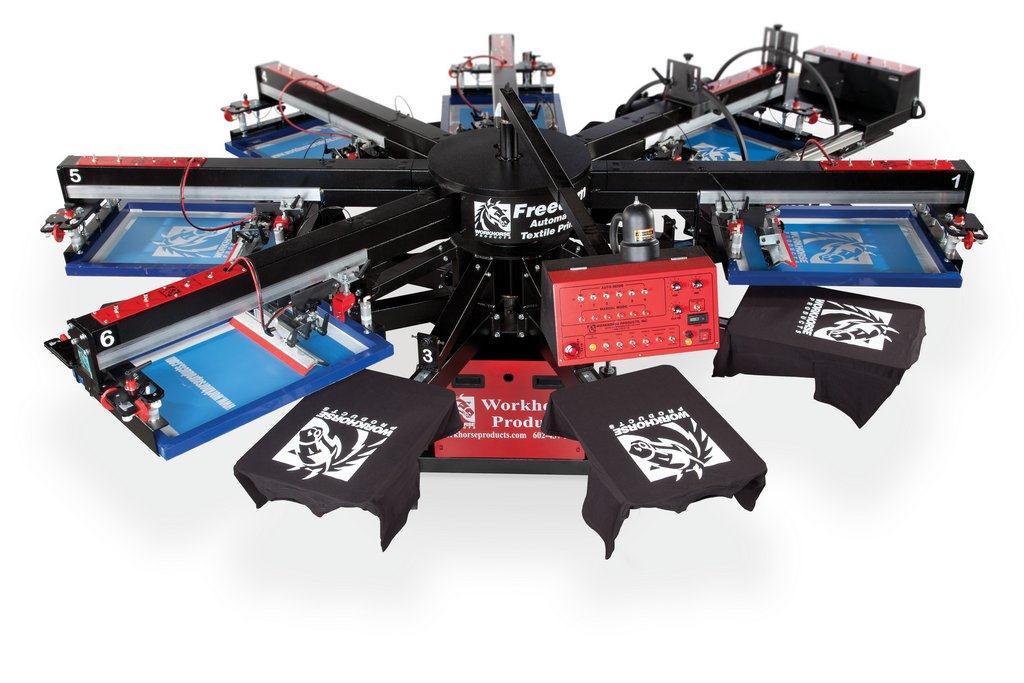
3 Introduction: The Freedom is the epitome of simple as it relates to screen printing. It s simple to set up, simple to operate, and simple to maintain. That said, The Freedom does not limit you to simple designs or small jobs. This machine turns any manual press operator into a mass producing printer. Freedom s fast indexing speed, simple to use controls and precise micro registration ensure that setups are as fast and easy as with your manual press. Add our patented Flashback to the Freedom and Workhorse has re-written the book on affordable high production while keeping it simple. Automating your manual shop gives you freedom from: long hours at the press, aching elbows and wrists, late deliveries, high labor costs, and the list goes on. Features and Specs: Power Options: 110v Single Phase, 50-60hz, 10 amps Air Requirements: 6-8: 120psi Construction: All steel construction. Polyurethane Airline Standard Print Size: 16 x 18 (41 x 46cm) Features: Fast squeegee and flood angle, pressure adjustment Double print stroke per screen for more opacity on dark garments Independent head control for easy job setup and registration Non-warping solid aluminum platen Double index, run two jobs simultaneously Adjustable print stroke Micro registration front & back for fast setups One knob quick change squeegee Precision milled Registration fork on every print head for exact registration Easy release platens Fast production rate - 60 doz./hr. Two year limited warranty 3
 Weight: Freedom 6-8:")
4 Dimensions: Freedom 6-8: 10.5ft (4m) Weight: Freedom 6-8: 2900lbs built 4

5 Standard Operating Guide: Print Head Selector Switch: Each print head has its own selection switch that is independent of all others and may be set in any one of the following positions; OFF - Single, Print Stroke & Double Stroke. During a print cycle those heads in the OFF position will remain at rest. The remaining head(s) will print after the pallet table has raised up, then upon completion the pallet table will lower and rotate to the next station while the flood stroke is occurring. If a double print stroke is required for any head(s), the pallet table will not rotate after lowering but will rise again in the same position for the second print cycle before continuing to the next station. 2. Manual Print Buttons: Each print head has its own numbered button, when one is depressed the pallet table will raise and the corresponding print head will print. The table will then lower but no table rotation will occur (used primarily to check registration). 3. Emergency Stop Button: When activated the air pump valve will cycle and release all air from the printer and cut power to all systems. (Note It is very important that the table be in alignment before reenergizing the emergency stop). 4. In Position Indicator: Before the press can begin any cycle or command the press must be in position meaning the correct sensors are reading for the command to begin. 5. Front/ Rear: Front Position; The squeegees will remain in the printed-rear position to leave the screen flooded for air dry inks. Rear Position; The squeegees will remain in the flood-front position to leave the screen opened and not flooded, used for most non air-dry inks such as plastisol. 6. Table Up/Down: In manual mode this will manually raise the table or lower the table, generally used during setup or registration. 7. Print On/ Off: If a squeegee requires service, the activation of this switch will release the air to the print cylinders so that the squeegee may be removed for cleaning, revised, replaced or to be able to adjust the squeegee angle and pressure adjustment. Flipping the switch to the original position will again supply air to the heads allowing operations to continue. 8. Sample: After registering a job it may be necessary to run a single sample to verify proper registration. Load test canvas, turn the sample on and the machine will print once on ever head that is turned on. 5
6 9. Begin/ End Production: Begin Production is used when first starting a production run. Engage Auto Start, then push Production Begin/End Button within 3 seconds. The pallet table will rotate and activate each head in turn as it proceeds around. When all heads have begun printing Auto Mode automatically begins. End Production: When finishing with a run, load your last shirt at Load On Station and push Production Begin/End Button. As the machine indexes, each head will deactivate in turn after printing and the machine will stop when the last shirt is completed. 10. Auto On/ Off: ON; Will start the printer into production run (flood, rotate and print). The table will begin rotation within 3 seconds of switching to Auto/On. Speed is controlled by the delay timer or the foot switch. OFF; In the manual stop position the table may be raised and lowered using the Table Up/Down Switch. The table can be rotated manually by hand. To print a desired head, select the number of the appropriate head and push that number switch. The table must be in the down position when printing a head. 11. Fuse: Used for circuit/ equipment protection if a fault occurs. For trouble shooting see question #1 in the FAQ section. 12. Power Indicator: Inline with the fuse above it, if a fault occurs blowing the fuse this light will be off. Under normal conditions this light will be on for the entire duration the press is on. 13. Main Power Switch: On Position: 110 Volt is supplied to the DC converter, computer and main air valve supplying air to the system. Off Position: Power is cut to main controls and air is released through main dump valve. (Note it is very important the table be in the proper alignment before energizing the main power switch). 14. Counter: Reset before each production run to keep track of the number of shirts printed. 15. Foot Pedal On/ Off: On position: To begin the production cycle, push the foot pedal down. When each print cycle is completed, the foot pedal must again be depressed in order for the cycle to start. Off Position: The delay Timer will energize and control the start of the next cycle. 16. Print Timer: This timer controls the time the pallets will remain in the up position while printing. Set the knob to the number that allows the slowest squeegee to complete its print stroke before the table lowers. 17. Delay Timer: After the print cycle is completed, the pallet table will lower and delay timer will be energized. Adjust the knob to the desired time for loading and unloading between print cycles. After the preset time is reached the table will rotate and begin the next print cycle. The delay timer is calculated in 1=1 sec. 18. Flood Timer: This timer controls the time the pallets will remain in the up position while printing. Set the knob to the number that allows the slowest squeegee to complete its print stroke before the table lowers. 6


7 Front Screen Hanger Micro Front Plate Part A Screen Clamp Part B Rear Screen Hanger Rear Screen Hanger Part C Screen Clamp Part B 7


8 Micro Adjustments (Left Side) Large Lever Part D Fitting Elbow Part E Fender Washer Part F Flange Nut Part I Micro Lock Cap Part J Knurled Knob Part G Micro Target Label Part H Micro Adjustments (Right Side) Large Lever Part D Flange Nut Part I Fitting Elbow Part E Fender Washer Part F Micro Lock Cap Part J Knurled Knob Part G Knurled Knob Part G Micro Target Label Part H 8
 Hex Bolt Part K Flange Nut Part I Nylon Lock")
 Right Side) Flange Nut Part H Nylon Lock Nut")

9 Micro Adjustments Disassembled (Front Screen Hanger Left Side) Hex Bolt Part K Flange Nut Part I Nylon Lock Nut Part L Micro Lock Cap Part J Close Up View (Picture Above) Micro Adjustments Disassembled (Front Screen Hanger Right Side) Flange Nut Part H Nylon Lock Nut Part L Flat Washer Part M Wave Washer Part N Micro Lock Cap Part J 9
 Part T Hex Bolt Part R Knurled Knob Part G Hex Bolt Part S")
 Part Q Hex Bolt Part S Knurled Knob Part G Hex Bolt Part R")
10 Micro Adjustments (Front Screen Hanger Left Side) Jam Nut Spring Part O Part P Rod End (RH) Part Q Jam Nut Part O Wave Washer Part U Rod End (LH) Part T Hex Bolt Part R Knurled Knob Part G Hex Bolt Part S Micro Adjustments (Front Screen Hanger Right Side) Jam Nut Part O Wave Washer Part U Rod End (LH) Part T Jam Nut Spring Part O Part P Rod End (RH) Part Q Hex Bolt Part S Knurled Knob Part G Hex Bolt Part R 10
 Part Q Hex Bolt Part R Micro Top Plate Part V Hex Bolt Part X Micro Adjustments")
 Part Q Micro Bottom Plate Part W Hex Bolt Part X Micro Top Plate Part V Hex Bolt Part R")
11 Micro Adjustments (Front Screen Hanger Left Side) Rod End (LH) Part T Hex Bolt Part S Micro Bottom Plate Part W Knurled Knob Part G Rod End (RH) Part Q Hex Bolt Part R Micro Top Plate Part V Hex Bolt Part X Micro Adjustments (Front Screen Hanger Right Side) Hex Bolt Part S Rod End (LH) Part T Hex Bolt Part S Rod End (LH) Part T Knurled Knob Part G Rod End (RH) Part Q Micro Bottom Plate Part W Hex Bolt Part X Micro Top Plate Part V Hex Bolt Part R 11


12 Micro Adjustments (Rear Screen Hanger Right Side) Flange Nut Part I Hex Bolt Part X Flange Nut Part Y U-Bracket Hex Bolt Part Z Part AA 4 Prong Knob Part AB Micro Adjustments (Front Screen Hanger Right Side) Bottom View U-Bracket Part Z Jam Nut Part AC Hex Bolt Part AA Spring Part AD 12


13 Micro Adjustments (Rear Screen Hanger Left Side) Lever Rear Screen Hanger Part AE Part C U-Bracket Stopper Part AF Flange Nut Flange Nut Hex Bolt Flange Nut Part I Part I Part X Part Y Part AG Micro Adjustments (Rear Screen Hanger, Left Side, Front View) Flange Nut Part I Hex Bolt Part X Flange Nut Part Y Shoulder Bolt Part AH Female Rod End Part AI 13

14 Print Head Control Panel (Top Half) Flow Plate Part AJ Plastic Snap Bushing Part AK Toggle Valve Part AL Toggle Valve Part AL 14

15 Print Head Control Panel (Bottom Half) Flow Plate Part AJ Flow Control Part AM Flow Control Part AM 15

 Flow Control Part AM Male Tube Fitting Part AQ Male Tube Fitting Part")
16 Print Head Control Panel (Internal Top Half) Flow Plate Part AJ Branch Tee Part AN Fitting Elbow Part AP Toggle Valve Part AL Black Poly Air Line 1/4 Part AO Fitting Elbow Part AP Part AN Toggle Valve Part AL Print Head Control Panel (Internal Bottom Half) Flow Control Part AM Male Tube Fitting Part AQ Male Tube Fitting Part AQ 16


17 Front Screen Hanger Plate (View From Underneath) Socket Head Screw Part AR Micro Bottom Plate Part W Rear Stroke Stops, Squeegee Rail Lever Part AE Rear Screen Hanger Part C Lever Part AE Alum. Squeegee Track Part AT Squeegee Stop Part AS 17


18 Rear Screen Hanger Lever Part AE Rear Screen Hanger Part C Lever Part AE Rear Stroke Stop Lever Part AE Spring Part AU Squeegee Stop Part AS Spring Part AU Vinyl Cap Part AV Swivel Pad Part AW Lever Part AE 18
 Hex Bolt")

19 Squeegee Carriage Carriage Wheels Part AX Squeegee Carriage Part AY Stroke Cylinder (Mounted) Hex Bolt Part AZ Stroke Cyl. Mount Bracket Part BD Stroke Cyl. 20 Part BA Hose Clamp Part BB Fitting Elbow Compact Part BC 19


20 Stroke Cylinder to Squeegee, Shoulder Bolt Assy. Flat Washer Part M Female Rod End Part AI Spring Part BE Nylon Lock Nut Part BF Stroke Cylinder to Squeegee Carriage Mounting Shoulder Bolt Part EP Flat Washer Part M Female Rod End Part AI Spring Part BE 20


21 Assembled Squeegee carriage (Front View) Male Rod End Part BJ Flipper Block Part BG Squeegee Pin Part BH Angle Stop Barrel Part BI Flip Cylinder, Clevis and Spade Bolt Hex Nut Part BK Clevis Kit Part BL Spade Bolt Part BM Jam Nut Part BN 21

22 Flip Cylinder (View from Below) Fitting Elbow Compact Part BC Flip Cylinder Part BO Fitting Elbow Compact Part BC Flange Nut Part BP Hex Bolt Part BQ 22


23 Flipper Frame Assembled (Right View) 4 Prong Knob Part BU X-Large Lever Part BV Bronze Bushing Flanged Part BR Shoulder Bolt Part BS Squeegee Adj. Weldment Part BT Flipper Frame Assembled (Left View) Bronze Bushing Flanged Part BR Shoulder Bolt Part BS Squeegee Adj. Weldment Part BT Shoulder Bolt Part BS 23
 4 Prong Knob Part BU Male Rode End Part BJ X-Large")

24 Squeegee Pressure Assy. (Installed) 4 Prong Knob Part BU Male Rode End Part BJ X-Large Lever Part BV Sq. Pressure Adj. Assy. Part BW Squeegee Pressure Assy. 4 Prong Knob Part BU Male Rod End Part BJ Jam Nut Part BX Shoulder Bolt Part BY Sq. Pressure Adj. Assy. Part BW 24
 Part CF")
25 Complete Control Box Lamp Part CD Control Panel Part CE Control Box (empty) Part CF 25


26 Complete Control Box (Left Half) Toggle Switch Part CI Button Switch Part CJ Button Switch Part CJ E-Stop Switch Part CG Lamp Part CH Toggle Switch Part CI Complete Control Box (Right Half) Potentiometer Part CK Toggle Switch Part CL Digital Counter Part CM Part CN Toggle Switch Part CL Lamp Part CH Fuse Holder Part CO 26
 Part")
27 Complete Control Box (Rear View) Flange Bolt Part BZ Flat Washer Part CB Pan Head Screw Part CA Control Arm (Inner) Part CC 27

 Part CT Socket Head Screw Part CQ")
28 Table Up Switch Flat Washer Part CB Pan Head Screw Part CA Snap Action Switch Part CP Main Shaft Bushings Socket Head Screw Part CQ Hex Bolt Jam Nut Hex Nut Part CR Part BX Part CS Bearing Set (3) Part CT Socket Head Screw Part CQ 28

29 Wheel, and Print Arm Assembly Flange Bolt Part CU Flange Bolt Part CU Flange Bolt Part CU Flange Bolt Part CU Flange Bolt Part CU Flange Bolt Part CU Flange Bolt Part CU Flange Bolt Part CU 29

30 Registration Fork Flat Washer Part CV Flange Bolt Part CW Registration Fork Part CX Flat Washer Part CV Flange Bolt Part CW 30

31 Registration Fork, Cam Bearing (Rear View) Flange Bolt Part CW Flange Nut Part BP Flat Washer Part CV Flange Bolt Part CW Flat Washer Part CV Flange Nut Part BP Hex Nut Part CY Flat Washer Part CZ 31

32 Cam Bearing Assy. Square Head Bolt Part DA Square Head Bolt Part DA Jam Nut Part BX Jam Nut Part BX Registration Bearing Part DC Number Label (1-12) Part DB 32
 Square Head Bolt Part DA Square Head Bolt Part DA Jam")
33 Cam Bearing Assy. (To View of Arm) Square Head Bolt Part DA Square Head Bolt Part DA Jam Nut Part BX Jam Nut Part BX Vertical Mylar Ruler Part DD 33

34 Platen Bracket Hex Nut Part DE Hex Nut Part DE Hex Bolt Part DF Hex Bolt Part DF Flat Washer Part M Flat Washer Part M Hex Bolt Part DG Hex Bolt Part DG Cam Lever Left Part DH Cam Lever Right Part DI Flat Washer Part M Flat Washer Part M Hex Bolt Part DG Hex Bolt Part DG Cam Lever Left Part DH Cam Lever Right Part DI Flange Nut Part BP 34

35 Platen Bracket (Side View) Flat Washer Part M Nylon Lock Nut Part DC Flange Nut Part BP Flat Washer Part M Flange Nut Part BP Flange Nut Part BP Flat Washer Part M Hex Bolt Part DF Hex Bolt Part DF 35


36 Communication Switch, Dummy Plug (Installed) Flat Washer Part CB Pan Head Screw Part CA Communicator Bracket Part DK Communicator Plug Part DJ Snap Action Switch Part CP Communicator Plug Part DJ 36


37 Table Up Switch Flat Washer Part CB Pan Head Screw Part CA Snap Action Switch Part CP In Location Switch (Installed) Snap Action Switch Part CP Pan Head Screw Part CA Flat Washer Part CB 37
 Black Air Line 3/8 Part DO Red Air Line 3/8 Part DP Fitting")
 Flow")

38 Index Cylinder, Clevis (Installed) Index Cylinder Flow Controls (Installed) Black Air Line 3/8 Part DO Red Air Line 3/8 Part DP Fitting Elbow Part DL Index Cylinder Part DM Clevis Kit Part DN Male Connector Part DQ Index Cylinder Rear Mount, Fork, and All thread (Installed) Flow Control Part AM Male Connector Part DQ Part DM All Thread Part DR Hex Nut Part CY Rear Index Clevis Part DS Index Cyl. Rear Mount Part DT Fitting Elbow Part DL 38


39 Index Block (Installed) Socket Head Screw Part DU Socket Head Screw Part DU Index Fork Part DV Index Block Mount Plate/ Hardware (Installed) Nylon Lock Nut Part DW Nylon Lock Nut Part DW 39
 Index Shock")

40 Index Shock (Installed) Lift Cylinder (Installed) Index Shock Part DX Fitting Elbow Part DL Lift Cylinder Part DY Connect- Part DZ 40

41 Index Block Cylinder, Clevis (Installed) Index Cylinder Part DM Fitting Elbow Part DL Clevis Kit Part BL Fitting Elbow Part E Flip Cylinder Part BO Fitting Elbow Part E Red Air line 1/4 Part EA Black Air Line 1/4 Part EB 41
42 Index Block Cylinder, (Lower Mounting Hardware, Installed) Fitting Elbow Part E Flange Bolt Part CU Flange Nut Part CU Hex Bolt Part EC 42


43 Male Connector Part DQ Muffler Part EE Valve Single Part ED Muffler Part EE Male Connector Part DQ Muffler Part EE Flow Control 1/4 Part EF Flow Control 3/8 Part EG 43

 Power Supply")
44 Dump Valve (Installed) Dump Valve Part EH Male Connector Part DZ Male Connector Part DZ Muffler Part EI Power Supply (Installed) Power Supply Part EJ 44
")

45 PLC (BNR Box, Installed) Complete PLC Part EK Prog. Memory Card Part EA 45
 Fitting Elbow Part BC Male Connector Part DQ LockOut Valve")
46 Main Air Assy. (Installed) Fitting Elbow Part BC Male Connector Part DQ LockOut Valve Part EM Filter/ Regulator Part EN Secondary Filter Part EO 46
47 WARNING! RISK OF ELECTRICAL SHOCK! Turn ALL power to unit OFF before service. All service should be done by or under the supervision of a trained technician Javelin Control Box, Non Touch Screen: 47
48 48
49 50 Wire Cable, Wiring: 49
50 50
51 51

52 7/10 Stack Wiring: 52
53 Head Plumbing/ Wiring: 53
54 Screen Clamp Plumbing: 54
55 Flip Cylinder Plumbing: 55
56 Print Arm Plumbing: 56


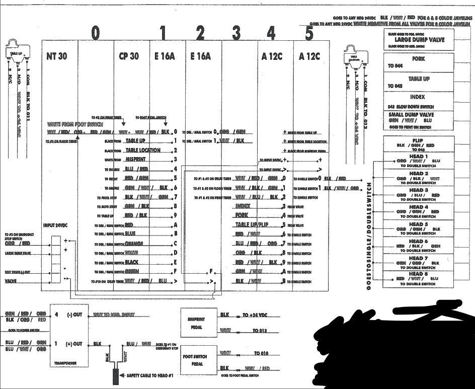
57 FAQ: WARNING! RISK OF ELECTRICAL SHOCK! Turn ALL power to unit OFF before service. All service should be done by or under the supervision of a trained technician 1. My Freedom will not turn on. If there is no air, the press will give the appearance that there is no power, but actually there is no air. Turn the Main Power switch on. The emergency stop button should be in the out position, on newer machines the light should be off when it is set correctly Make sure the safety cable is plugged in correctly Make sure the power cable is plugged in, you can check that the machine has power by turning the registration lamp on Image 1 Check the fuse to the left of the power switch Check the Fuse at the power supply on earlier models, Located in the base, attached to the frame. If all of these things are good we can begin to trouble shoot. Start with bypassing the safety cable for the first test. On newer machines you will need to pull the flow plate off the top of the print arm and find the connection point for the cables. Use wire nuts and connect the wires together this will close the circuit. If this fixes the problem you will need to figure out what is wrong with the cables, on older machines the safety cable makes the main connection near the center of the machine. You will need to pull the hole plugs off the top of the print arms and pull the wires through, remove the blue wire nuts and twist the wires together. Early Style Power Supply Output Image 3 Current Style Power Supply Input Input output If this does not correct the problem will need to get a digital volt meter. Using a digital Volt/Ohm meter in the ACV setting ( ) verify there is 110 volts AC going to into the power supply. If the power supply is getting the correct input voltage next check for 24VDC coming on the out of the power supply. If the correct voltage is coming from the power supply we need to go the PLC where the connections are and see if we have 24vdc there, On older Javelins the -24vdc is connected direct to the PLC and the +24 vdc goes through safety circuit. On javelin pro the +24vdc is connected direct to PLC and the -24 vdc goes through safety circuit. 57

 showing it has made Contact and it is ok to begin the print stroke.")
58 2. The Press tables up but will not print. The normal sequence for this process is the table raises then just sits there waiting to print and nothing happens until you turn the power off. Then you start all over and it still just sits there again. The machine will not print if the table up sensor (Image 4) is not making a connection to the PLC, on older javelins and on Freedoms this sensor will register under green lights #1 This is in the first bank of Green lights in the E16A The input is #1 to the PLC (Image 5) showing it has made Contact and it is ok to begin the print stroke. Image 4 Image 5 On either PLC if the connections are not being made, the table up switch will need to be adjusted or replaced. With machine off locate the table up switch, note the location of the current position of the black and white wires, remove the wires. Next using a digital Volt/Ohm meter in the resistance setting (omega symbol Ω) to test the switch for continuity place one probe on COM terminal of the switch and the other probe on the NO terminal. With the probes in place depress the switch, the meter should have a low reading or produce a beep, if the meter reads zero or does not produce a beep the switch will need to be replaced. If the switch is functioning properly a simple adjustment may be needed. To adjust the switch, with your thumb on the base of the tab where it connects to the switch body, bend the tab down towards the floor just enough that it makes adequate contact with surface of the carousel when the press tables up. Adjust as needed until press functions properly. 3. Table will not lower after printing This normally only on older Javelins and Freedoms, After the Press has made the print stroke the PLC is looking for the print timer to finish, once this happens it sends a input to the input labeled 0 in the E16A (Image 6) if the #2 yellow light is on under the A12C this is output to the print timer. If that light is still on your print timer has not cycled. Image 6 58
59 3. (Continued) You should open the control box and make sure the connections are secure at the timer and the speed pot. If all the connections look good will need to get a VOM and check for the 24vdc going to the timer and through the timer back to base. On the orange power lamp, there are 2 purple wires one is the -24vdc leg this is normally connected with a White blue red wire. Expose this connection by removing the blue wire nut. Then with the machine still in the middle of the cycle we can to see if there is +24vdc going to the delay timer and coming out of the timer. If this all test good then we need to test the wire that comes from the timer and runs to the input #0 under the E16A If it test bad we can switch the timer around with one of the other timers in the control box, I would use the delay timer so we are able to get past the flood time with a manual stroke. If this still does not correct your problem or at least move it the it is most likely a bad wire 4. My Freedom will not table up Depending on the command we give the machine will direct us on where to start trouble shooting. Say we hit manual print and the squeegee does not move it just sits there and the press does nothing, then we should check that the press is in location and that the PLC is showing location light is on. Freedom s and older Javelin will have Green light #2 on under the E16A. If the sensor is not made the machine will not perform. Image 7 Say we hit the manual print and the squeegee moves forward and then the table just sits there, then we should then check if we turn the machine off and back on will it table up? If so, then we need to check on the PLC is the orange light #1 on and the flood timer not timing out? This will be on older javelins and Freedoms. If the light is on then the flood timer has not cycled, and we need to diagnose the flood timer and see if we have a loose connection. You should open the control box and make sure the connections are secure at the timer and the speed pot. If all the connections look good will need to get a VOM and check for the 24vdc going to the timer and through the timer back to base. On the orange power lamp, there are 2 purple wires one is the -24vdc leg this is normally connected with a White blue red wire. Expose this connection by removing the blue wire nut. Then with the machine still in the middle of the cycle we can to see if there is +24vdc going to the Flood timer and coming out of the timer. If this all test good then we need to test the wire that comes from the timer and runs to the input #0 under the E16A Another Scenario is you just hit table up and nothing happens machine will do other functions but just will not table up, Then we start looking at other items for example Flashbacks on the machine interfering with the output, first step is to check the simplest thing. Are the air supplies turned on to the flashbacks, if not turn them on as this allows the element tray to drift forward. 59
60 Are all the Flashback cables plugged in and Dummy plug in the last Flashback? If this is correct is the #5 orange light on? If yes at this point put the dummy plug in to the base of the machine and then try to table up again if this corrects the problem then we know it is somewhere in the flashbacks if not then we need to go directly to the valve and check it for 24vdc. If the valve has 24vdc then we have a bad valve. If the Dummy plug in the base solved the problem we need to go to the Flashback trouble shooting for more in depth testing of the Flashbacks. Refer to the Flashback Tech Guide for further testing. 5. The press will not print. Press tables up then just sits there until you turn the power off. When the machine raises it hits a switch that then sends a signal to a PLC that the table is up. If the switch is not making contact, the machine will not finish it needs the switch to continue on. Normally just lowering the switch or fixing a loose connection will cure the problem however you may need to change the switch if it is damaged or covered in spray adhesive. On some machines it is in between the #3 and #4 print heads on others it is in front of the on Load and un-load stations. With the machine off locate the table up switch, note the location of the current position of the black and white wires, remove the wires. Next using a digital Volt/Ohm meter in the resistance setting (Upside down omega symbol) to test the switch for continuity place one probe on COM terminal of the switch and the other probe on the NO terminal. With the probes in place depress the switch, the meter should have a low reading or produce a beep, if the meter reads zero or does not produce a beep the switch will need to be replaced. If the switch is functioning properly a simple adjustment may be needed. To adjust the switch, with your thumb on the base of the tab where it connects to the switch body, bend the tab down towards the floor just enough that it makes adequate contact with surface of the carousel when the press tables up. Adjust as needed until press functions properly. 6. My machine spins before I am ready for it to. This requires you to add more Delay time, turn the delay time up for longer flash times especially if your using Flashback. You can also turn the foot pedal on and step on the pedal when ready for the machine to turn 7. The Press tables down before completing the print. Adjust the print timer on the control box to a higher number to increase print dwell time. Pull the base panel off the press an locate the PLC. With the press powered on, and the pallet table down check the PLC for green light 1.1 If the 1.1 light is on the table up switch is stuck in the on position. Check the condition of the switch and replace if required. With machine off locate the table up switch, note the location of the current position of the black and white wires, remove the wires. Next using a digital Volt/Ohm meter in the resistance setting (omega symbol Ω) to test the switch for continuity place one probe on COM terminal of the switch and the other probe on the NO terminal. With the probes in place depress the switch, the meter should have a low reading or produce a beep, if the meter reads zero or does not produce a beep the switch will need to be replaced. 60

61 7. (Continued) If the switch is functioning properly a simple adjustment may be needed. To adjust the switch, with your thumb on the base of the tab where it connects to the switch body, bend the tab down towards the floor just enough that it makes adequate contact with surface of the carousel when the press tables up. Adjust as needed until press functions properly. (Older Javelins) If the switch is working properly, you may have a defective print timer. Locate the print timer inside the control box by following the two wires from the print timer control to the print timer. Replace the print timer. The print timer may be timing out early also from static discharge and it may need to be grounded out with a resistor to drain any left over power in the line. See wiring diagrams section for resistor wiring specs. 8. The Squeegee s Flip to hard or not fast enough When the squeegee flips it is controlled by the flip valve it the valve is set to fast it can cause the squeegee to snap over to fast slinging the ink forward (make sure print head is not running to fast forward causing the ink to fly forward) Adjust the flow controls on the flip valve to make squeegee flip at a controlled speed, by turning clockwise it will slow the flip. Counter clock wise will speed it up To test the flipping motion put the machine in automatic with 2 strokes and make sure the flip is fast enough on the table down after the first print stroke and when the table raises for second print stroke. Remember though that the motion does not need to be super fast, nice and controlled motion is ideal. 61


62 9. The Squeegee s lose pressure before completing the print stroke. This condition is usually a defective flip cylinder. It is usually worse on one head, but can affect other heads as well. You may hear an unusual flow of air. The head with a defective flip cylinder may not even be one of the heads you are using, but it can still affect other heads ability to hold pressure. If you can hear air leaking when you have the print toggle switch in the on position we will need to find what is causing the leak. A weak cylinder can cause loss of pressure on a print stroke excessive pressure can cause it and ink that is really thick will give the same result as well. Printing with white ink is usually the biggest culprit for loss of pressure if this is the case we need to make sure the ink has been mixed really well before adding it to the screen. If a leak has been heard we need to check the flip cylinders to see if one or two are causing a exhaust of air. The reason for this is all the flip cylinders are branched together off the same valve and one being bad can cause issues at all the others. The best way to test is to raise the tables with the print on and if you have excessive air loss turn the print off and see if that stops the leak of air. If it does, turn the print back on and see if it continues to leak. If it does not, lower the tables and then raise the tables again. At this point if it begins to leak air start by kinking the red and black airlines that come out of the top of the flow plates and wrap with masking tape. Until you stop the leak, then open the airlines one at a time and see which one causes the leak keeping in mind more than one could be bad. Once you have found the bad cylinder it will need to be replaced. You could have a weak cylinder also and you can test for a weak one by just putting a ¾ wrench on the flip block and rotate the block back and forth and compare the weak ones with heads that are printing well you may see some variance in the pressure from head to head using your best judgment on which one is stronger you will want to change the weaker cylinder. It is not a bad idea to change out all flip cylinders at one time when pressure problems arise. If you had a leak with the print on and table up and you kinked all the airlines at every head and left them taped and the leak continued you may have a bad air valve that needs replacing. Locate the flip valve and kink the red and black coming off the top of it and see if that does not stop the leak before deciding to replace the valve. 10. The heads flood but will not print. This condition usually indicates a defective stroke cylinder. While this head is hung in the flooded position, after other heads have completed there print stroke. You will usually here air leaking. If you hear air leaking, turn both flow controls on top of the print head all the way clockwise. if this stops the air leak you more than likely have a defective stroke cylinder and will need to replace it. But you may also have a valve that is causing it and the easiest method to test that is move airlines blue and green from valve with bad head to valve with good head remembering to open the flow controls that we had closed previously if the problem stays on the effected head it is a bad cylinder, but if the problem then moves to a different head it is a bad valve. If you do not hear any airflow when the print head is hung in the flooded position after all other heads have finished printing and table has come down. You may have a stuck valve and you can test this also by moving the airlines from known working head and the bad one and if you do move the problem you will know for sure the valve is bad. You may also be able to add to tool oil into the valve and get it to function, this may loosen the valve up and keep it running to get through a job. But this is not a permanent fix the valve will need to be replaced 62
63 Freedom indexer is jumping out of capture block: When the machine cycles its stopping point is the index shock. If the press is jumping past the stopping point the vertical cylinder that holds the capture block to the bottom of the pallet arm may have come loose or the speed of the indexer is set to fast. When the vertical cylinder is mounted to the angle iron of the capture arm assembly it will normally cut in to the powder and you will see a gap in between the bottom bolt and the mounting bolt of the cylinder. This needs to be adjusted so the cylinder can pull the capture block to the pallet arm where the block has a good hold on it. Once this has been adjusted cycle the machine a couple of times to test If the speed has been set to fast adjust the flow control on the red airline of the horizontal cylinder by screwing it in and then test the machine by cycling it 63
64 Freedom index adjustments: The speed of the index is controlled by adjusting the flow control with red air lines located under the index cylinder. The flow control with black air lines controls the speed at which the indexer retracts to start position. The shock absorber catches the indexer and brings it to a stop. The shock absorber should be set to #2. If the shock absorber is in good working order this setting will work. Adjust the flow control with the red air lines, located under the index cylinder. Clockwise to slow the index down, and counter clockwise to speed it up. Let the press run a few indexes then re-adjust so that the pallet table comes to nice stop. If you cannot get the pallet table to stop correctly after the above steps, make a slight adjustment to the index shock setting. Going below a setting of #2 will make the shock stiffer, and going above #2 will make to shock softer. 64

65 Index Shock Adjustment: The type 1 shock has a scale engraved on the ring at the end of the shock. This ring butts against the threaded body of the shock where there is a dimple indicating the setting of the shock. When the table indexes the shock should be adjusted to bring the table to a stop, bottoming out all the way without shaking. If the shock is to stiff it will not compress enough on impact causing registration problems the same issues can occur if the shock is set to soft as well as damage to the press. The shock is very sensitive to change, adjust with caution moving is fractions between the numbers. The lower the number the stiffer the shock gets. Note: the number indicated in the picture above does NOT reflect what the shock setting is on each press. Always consult a trained Workhorse products technician before any adjustments are made. 65
66 Comprehensive Parts List. Description P/N Description P/N A. Front Micro Assembly SA-0060 AG. Kep Nut (1/4-20) 42-KEPS B. Screen Clamp I-0003 C. Rear Screen Clamp Hanger T-0210 D. Large Lever (5/16-18 THD) K-0006 E. Fitting Elbow 5/32T X 1/8 NPT F. Fender Washer 43-FND G. Knurled Knob SA-0103 H. Micro Target Label I. Flange Nut 42-FLG J. Micro Lock Cap I-0514 K. Hex Bolt (5/16-18 x 2) 41-HTB L. Nylon Lock Nut 42-NYL M. Flat Washer 43-FLT N. Wave Washer 43-WAV-M8-10 O. Jam Nut 42-JAM P. Spring Q. Rod End (RH) I-0265 R. Hex Bolt (3/8-16 x 1.5) 41-HB S. Shoulder Bolt T-1977 T. Rod End, (LH) I-0266 U. Wave Washer 43-WAV V. Screen Clamp Cylinder A-0119 W. Screen Clamp Cylinder Foot F-0106Z X. Hex Bolt (1/2-13 x 3") 41-HTB Y. Flange Nut 42-FLG Z. U-Bracket Weldment WA-0128 AA. Hex Bolt (1/4-20 x 1) 41-HTB AB. 4 Prong Knob (5/16-24 THD) K-0002 AC. Jam Nut 42-JAM AD. Spring M-0319 AE Lever ( 5/16-18 x 1-9/16 STD) K-0005 AF. U-Bracket, Stopper I-0302 AH. Shoulder Bolt (5/16 x 1.75 ) 41-SB AI. Female Rod End (5/16-24) B-0004 AJ. Flow Plate I-0139-SCR AK. Plastic Snap Bushing 1" F-0154 AL. Toggle Valve AM. Flow Control A-0971 AN. Branch Tee (5/32 T x 10-32) A-0003 AO. Black Poly Air Line (5/32) PER FT A-0301 AP. Fitting Elbow (10-32 NPT x 5/32TUBE ) AQ. Male Tube Fitting (1/4 x 1/4) A-0032 AR. Button Head Screw (5/16-18 X 1) 41-BHCS AS. Squeegee Stop Assy. SA-0025 AT. Aluminum Squeegee Track T-0167 AU. Spring, Squeegee Stop M-0045 AV. Vinyl Cap F-0904 AW. Swivel Pad F-0902 AX. Squeegee Carriage Wheel B-0101 AY. Squeegee Carriage WA-0153 AZ. Hex Bolt (1/4-20 x 1/2 ) 41-HB BA. Stroke Cylinder 20" A-0140 BB. Hose Clamp A-0910 BC. Fitting Elbow Compact (1/4 T x 1/8) A-0015 BD. Stroke Cylinder Mount I-0294 BE. Spring, Stroke Cylinder M-0402 BF. Nylon Lock Nut 42-NYL BG. Flipper Block T-0201 BH. Squeegee Pin SA-0004 BI. Squeegee Angle Stop Barrel T-0095 BJ. Male Rod End (1/2-20) B-0006 BK. Hex Nut 42-HEX BL. Clevis Kit A
67 Comprehensive Parts List. Description P/N Description P/N BO. Flip Cylinder A-0102 CU. Flange Bolt (3/8-16 x 3/4) 41-FLG BP. Flange Nut 42-FLG BQ. Hex Bolt (3/8-16 x 4) 42-HB BR. Bronze Bushing, Flanged (3/8) B-0022 BS. Shoulder Bolt (3/8 x 3/4) 41-SB BT. Squeegee Angle Adj. Weldment WA-0101 CV. Flat Washer 43-FLT CW. Flange Bolt (3/8-16 x 1 1/2) 41-FLG CX. Registration Fork T-0059 CY. Hex Nut 42-HEX CZ. Flat Washer 43-FLT BU. 4 Prong Knob (1/2-20 THD) K-0017 DA. Hex Bolt Square Head (5/16-18 x 2) 41-SQH BV. X-Large Lever (3/8-16 THD) K-0014 BW. Squeegee Pressure Adj. Assy. SA-0005 BX. Jam Nut 42-JAM BY. Shoulder Bolt T-0913 BZ. Flange Bolt (5/16-18 x 1) 41-FLG CA. Flat Washer 43-FLT-8-10 CB Pan Head Screw (#6-32 x 1-1/4) 41-PHMS-6-50 CC. Control Arm (Inner) WA-0129 CD. Lamp DB. Number Label (1-12) (1-12) DC. Registration Bearing B-0012 DD. Vertical Mylar Ruler DE. Hex Nut 42-HEX DF. Hex Bolt (3/8-16 x 2-1/2) 41-HTB DG. Hex Bolt (5/16-18 x 2) 41-HB DH. Cam Lever, Left DI. Cam Lever, Right DJ. Harness, Communicator Cable CE Control Panel (Empty) I-0017-SCR DK. Communicator Bracket CF. Control Box (Empty) WA-0089 CG. Illuminated E-stop Switch CH. Lamp E-0901 CI. Toggle Switch (sp/st) E-0106 CJ. Button Switch, Red E-0991 CK. Potentiometer (110k ohm) E CL. Toggle Switch (sp/dt) E-0901 CM. Digital Counter E-0903 CN. ON/OFF Switch Main E-0104 CO. Fuse Holder, Panel Mount E-0912 CP. Snap Action Switch E-0982 DL. Fitting, Elbow, Male (3/8t x 3/8 npt) DM. Index Cylinder A-0104 DN. Clevis Kit A-0905 DO. Black Poly Air Line (3/8) A-0056 DP. Red Poly Air Line (3/8) A-0306 DQ. Male Connector (3/8 x 1/4p) A-0022 DR. All Thread T-0904 DS. Rear Index Clevis A-0904 DT. Index Cylinder Rear Mount A-0902 DU. Socket Head Screw(3/8-16x1-1/4) 41-SHCS DV. Index Fork T-2035 CQ. Socket Head Screw (3/8-16 x 1-1/2) 41-SHCS DW. Nylon Lock Nut 42-NYL CR. Hex Bolt (5/16 x 2) 41-HTB CS. Hex Nut 42-hex CT. Bearing Set (3pcs) I-0523 DX. Index Shock A-0962 DY. Lift Cylinder A-0106 DZ. Connector Male(3/8t x 3/8npt) A
68 Comprehensive Parts List. Description P/N Description P/N EA. Red Poly Air line (1/4) A-0054 EB. Black Poly Air line (1/4) A-0055 EC. Hex Bolt (3/8-16 x 2) 41-HTB ED. Valve Single A EF. Flow Control Fitting (1/4) A-0042 EG. Flow Control Fitting (3/8) A-0043 EH. Dump Valve A-0210 EI. Muffler (3/8) A-0031 EJ. Power Supply EK. Complete PLC E-0241 EL. Programmed Memory Card E-0059-P EM. Lockout Valve A-0097 EN. Filter Regulator, 1/2 gauge A-0143 EO. Secondary Filter A-0142 EP. Knob K-0008 EQ. Hex Nut 42-HEX ER. All Thread T-0915 ES. All Thread T-0901 ET. Hex Nut 42-HEX EU. Flow Control (Old Style) A-0201 EV. Pem Stud 44-FH EW. Lock Washer 43-LOK EX. Hex Nut 43-HEX EY. E-Clip F-0957 EZ. Shoulder Bolt 41-SB FA. Disc Washer 43-DIS
REV: 000. Super Seca Flash Cure Units
 REV: 000 Super Seca Flash Cure Units Table Of Contents Introduction 2 Standard Operating Guide 2 Features & Specs 2 External Layout 4-15 Internal Layout 16-24 Plug Guide 25 Wiring Diagrams 26-28 F.A.Q.
Table Of Contents. Introduction 3. Features and Specs 3-4. Standard Operating Guide 5. External Layout Internal Layout 35-47
 REV: 000 Javelin Table Of Contents Introduction 3 Features and Specs 3-4 Standard Operating Guide 5 External Layout 6-34 Internal Layout 35-47 Wiring/ Plumbing Diagrams 48-62 F.A.Q. 63-69 Screen Shots
TM ETRS-TM35FIN-ETRS89 WTG
 Noise calculation model: ISO 9613-2 General Wind speed: 8,0 m/s Ground attenuation: General, Ground factor: 0,4 Meteorological coefficient, C0: 0,0 db Type of demand in calculation: 1: WTG noise is compared
Installation, Maintenance & Parts Manual
 Installation, Maintenance & Parts Manual 2100 Series Center Drive Conveyors Table of Contents Warnings General Safety........................... 2 Introduction....................................... 2
SPARE CONNECTORS 2008
 SPARE PARTS MANUAL ART.NO.: 3208201 ENGLISH INDEX SPARE CONNECTORS AA-AR SPARE CONNECTORS AS-BK SPARE CONNECTORS BL-BZ SPARE CONNECTORS CA-CP 1x 2x 3x 4x SPARE CONNECTORS CQ-DM SPARE CONNECTORS DN-EL
Installation, Maintenance & Parts Manual
 Installation, Maintenance & Parts Manual Flat Belt Center Drive LPZ Conveyors Table of Contents Warnings General Safety........................... 2 Introduction.......................................
Set-up, Operation & Maintenance Manual
 Set-up, Operation & Maintenance Manual 2100 Series Center Drive Conveyors Table of Contents Warnings General Safety.................... 2 Introduction................................ 2 Product Description..........................
SELECTION LIST REVISION This book contains the following models: Chevy/GMC Dodge Ford
 SELECTION LIST ---------- REVISION 0 ---------- This book contains the following models: 1973-2002 Chevy/GMC 1994-2002 Dodge 1980-2002 Ford Form #64135-120102 WESTERN PRODUCTS P.O. BOX 245038 MILWAUKEE,
Flat Belt Center Drive LPZ Conveyors
 Flat Belt Center Drive LPZ Conveyors Installation, Maintenance & Parts Manual DORNER MFG. CORP. INSIDE THE USA OUTSIDE THE USA P.O. Box 20 975 Cottonwood Ave. TEL: 1-800-397-8664 TEL: 262-367-7600 Hartland,
Partner for Change : Appendix A
 11/8/217 Partner for Change - 218: Appendix A Practice Greenhealth Awards Probo.CI CEC_HOSPITAL no.35321 Partner for Change - 218: Appendix A Introduction Completion of Appendix A mandatory. Please indicate
Installation, Maintenance & Parts Manual
 Installation, Maintenance & Parts Manual 00 Series Center Drive Conveyors Table of Contents Warnings General Safety........................... Introduction....................................... Product
AUTUMN 2013 TIME SCHEDULE
 AUTUMN 2013 TIME SCHEDULE Instructor 110 A LC 3 M W F 830-920 195 L EEB 105 CRAIG 11903 11904 AA QZ T 930-1020 25 L MUS 219 11905 # AB QZ T 1030-1120 25 L DEN 213 11906 AC QZ T 1230-120 25 L SMI 107 11907
2200 Series Center Drive Conveyors
 2200 Series Center Drive Conveyors Installation, Maintenance & Parts Manual DORNER MFG. CORP. INSIDE THE USA OUTSIDE THE USA P.O. Box 20 975 Cottonwood Ave. TEL: 1-800-397-8664 TEL: 262-367-7600 Hartland,
Vacuum Automation 2.1. The future depends on good product choices
 Vacuum Automation 2.1 The future depends on good product choices Combined pump and gripper 432 433 Combined pump and gripper Introduction...434 Small...436 Medium...438 Large...452 Accessories...455 434
Table 1d - FSA for All Returns, Females Tax Year
 PR 10 Newfoundland and Labrador A0A 20,250 597,345 1,920 1,720 2,580 3,150 1,960 1,610 1,360 1,030 1,020 740 550 460 630 470 410 290 290 70 20 A0B 8,850 249,804 780 740 1,200 1,520 1,010 790 540 430 370
Guide blocks for ISO/VDMA cylinders
 Actuators Guide blocks or ISO/VDMA cylinders QA/8/51/ QA/8/61/ QA/8/81/ (long coupling) QA/8/85/ (short coupling) Ø 32 to 1 mm QA/8/61/ QA/8/51/ Conorms to ISO 6431, VDMA 24562 and NFE 49 3 1 Ensures protection
QA/8000. Guide blocks with plain bearings/ roller bearings Ø 32 to 100 mm
 Guide blocks with plain bearings/ roller bearings Ø 3 to mm Conorms to ISO 643, VDMA 46 and NFE 49 3 Ensures protection against external rotary and bending orces Guide rods run through bearings protected
SELECT 3-BURNER PROPANE BARBECUE Assembly Manual
 SELECT 3-BURNER PROPANE BARBECUE Assembly Manual 85-3096-2 (G31221) Propane 1 Year limited Warranty Read and save manual for future reference. Assemble your grill immediately. Missing or damaged parts
Parts List, Wiring Diagrams
 Parts List, Wiring Diagrams PAS180-300 SERIES PACKAGE GAS ELECTRIC UNITS TABLE OF CONTENTS PARTS LIST----------- 2-16 PARTS DRAWING - - - - - 17-28 WIRING DIAGRAMS - - - 29-52 Printed in U.S.A. 5/22/08
Installation, Maintenance & Parts Manual
 Installation, Maintenance & Parts Manual 3200 Series Flat Belt LPZ Conveyors Table of Contents Warnings General Safety........................... 2 Introduction....................................... 2
Combined pump and gripper Medium
 VGS 3010 H D W Dimension and connection W D H Feed pressure Vacuum Exhaust/blow mm mm mm 1 Housing VGS3010 23 30 Ø6 mm, 3x G1/8", M5 2 COAX cartridge 2:1 No COAX cartridge 65 2:2 COAX cartridge 2-stage
Push Button Units and Indicator Lights
 3SB3, Inscriptions, 22 mm Insert labels Push Button Units and Indicator Lights Push buttons (clear) and illuminated push buttons with a flat button can be fitted with insert labels for identification purposes,
Issue/Rev. 0.3 (2/04) Bulletin P
 Bulletin P") Form No. P0906.03 E-Type Transmitter Parts List Issue/Rev. 0.3 (2/04) Bulletin P0906.03 (Previous Design) Switch and Network Assembly The Switch and Network Assembly is no longer available. To replace
Form No. P0906.03 E-Type Transmitter Parts List Issue/Rev. 0.3 (2/04) Bulletin P0906.03 (Previous Design) Switch and Network Assembly The Switch and Network Assembly is no longer available. To replace
Tamil Nadu Public Service Commission
 ASSISTANT CONSERVATOR OF FORESTS DOE :02.12.2014 TO 09.12.2014 _ Subjcct:AGRICULTURE ~ Codc:ACFAG ~........ B X 41 AX 81 DX 121 o A 161 c l< 2 cy 42 CY' 82 Dy 122 13 x 162 B ~ J ox 4J c \ 83 D..( 123 c
MCC omponents Itasca Street Chatsworth
 omponents 21201 Itasca Street Chatsworth!"# $%!"# SMBJ5.0 THRU SMBJ170CA Features For surface mount applications in order to optimize board space Low profile package Fast response time: typical less than
KNOCK CYLINDERS CONTENTS ACTUATORS GENERAL CATALOG. Caution KNOCK CYLINDERS
 CAD drawing data catalog is available. ACTUATORS GENERAL CATALOG CONTENTS Features/Introductions of Variations 79 Double Acting Type Specifications 81 Order s 82 Inner Construction and Major Parts 83 Dimensions
The Product Range. Technical Data
 The Product Range Section 3.1 - Basic Cylinder Bore sizes (mm): 10, 16, 25, 32, 40, 50 The basic cylinder series satisfies the support and guidance requirements of a great diversity of applications. Various
Installation, Maintenance & Parts Manual
 Installation, Maintenance & Parts Manual 6100 Series Industrial Center Drive Conveyors Table of Contents Warnings General Safety......................... 2 Introduction....................................
CUSTOM ADD-ONS FOR ENGLISH UNITS
 Spindles Flange Piloted Slot Collet Jacobs Taper Morse Taper See note on next page for location in the Specification Code No. Description A B C AA Flange 2.625 3.619/3.621 5.313 AB Piloted Slot 2.3125
3200 Series End Drive Flat and Cleated Belt Conveyors
 00 Series End Drive Flat and Cleated Belt Conveyors Installation, Maintenance & Parts Manual DORNER MFG. CORP. INSIDE THE USA OUTSIDE THE USA P.O. Box 0 975 Cottonwood Ave. TEL: -800-97-8664 TEL: 6-67-7600
Safety 14 ga. Welded Plastic Bin Security Fire Resistant Gas Cylinder
 All Cabinets Ship Flyer CAB07B...Many in 48 hrs. Heavy Duty All Welded CABINETS 40 Models Safety 14 ga. Welded Plastic Bin Security Fire Resistant Gas Cylinder Powder Coated Finish Safety Cabinets are
Florida Dept. of State Summary Data 2016 Overvote-Undervote Report
 Florida Dept. of State Summary Data 6 Overvote-Undervote Report 5 6 9 5 6 9 5 6 9 5 6 9 5 6 9 5 5 5 5 5 A B C D E F G H 6 GENERAL ELECTION REPORT ON OVERVOTES AND UNDERVOTES Tabulation Device County EV
SMB5.0A(CA) - SMB440A(CA)
 - SMB440A(CA)") SMB5.0A(CA) - SMB440A(CA) SURFACE MOUNT TRANSIENT VOLAGE SUPPESSOR DIODE VOLTAGE RANGE: 5.0-440 V POWER: 600Wa t t s Features Mechanical Data Glass Passivated Die Construction Uni- and Bi-Directional Versions
SMB5.0A(CA) - SMB440A(CA) SURFACE MOUNT TRANSIENT VOLAGE SUPPESSOR DIODE VOLTAGE RANGE: 5.0-440 V POWER: 600Wa t t s Features Mechanical Data Glass Passivated Die Construction Uni- and Bi-Directional Versions
MODELS SA5000AC, SA7000AC, SA9000AC, SA12000AC
 OWNER S MANUAL MODELS SA5000AC, SA7000AC, SA9000AC, SA12000AC dead WEIGHT CaPaCITY (LBS.)* WARNING: READ INSTRUCTIONS CAREFULLY BEFORE ATTEMPTING TO INSTALL, OPERATE OR SERVICE THE STRONGARM ELECTRIC WINCH.
Microbore Hose, Assemblies & accessories
 bar DN2 and DN4 High pressure Microbore hose Technical data Microbore hose The microbore hose assembly, most commonly used to connect to a Minimess test point for pressure testing, has many other diverse
Triple Play Ramp Door OWNER'S MANUAL
 Triple Play Ramp Door OWNER'S MANUAL TABLE OF CONTENTS Introduction 2 Safety Information 3 Operation 4 To Operate the Triple Play Ramp Door Touchpad: 5 Patio Mode 5 Ramp Mode 5 Closing the Triple Play
Application. Additional Features. Description. Features
 1199 Series Packaged Valve and Motor Assemblies Bulletin 1199 January 2010 Direct coupled / packaged assembly no linkage to adjust. Easy setup. Accurate, consistent response. Wide selection of valve types
Heavy Duty Actuators CONTROLS. Pneumatic Actuators for Quarter-Turn Valves and Dampers Torques to 1,600,000 in. lbs. Double Acting and Spring Return
 CONTROLS Division of A-T Controls Heavy Duty Actuators Pneumatic Actuators for Quarter-Turn Valves and Dampers Torques to,600,000 in. lbs. Double Acting and Spring Return THD S E R I E S The Triac line
400W, 5V - 188V Surface Mount Transient Voltage Suppressor
 400W, 5V - 188V Surface Mount Transient Voltage Suppressor FEATURES Low profile package Ideal for automated placement Glass passivated junction Excellent clamping capability Fast response time: Typically
Installation, Maintenance & Parts Manual
 Installation, Maintenance & Parts Manual 4100 Series End Drive Table of Contents Warnings General Safety........................ 2 Introduction.................................... 2 Product Description..............................
SAMYANG ELECTRONICS SMBJ SMBJ440CA TRANSIENT VOLTAGE SUPPRESSOR. Features. Mechanical Characteristics
 SAM YANG SAMYANG ELECTRONICS TRANSIENT VOLTAGE SUPPRESSOR BREAKDOWN VOLTAGE: 5.0 --- 440 V PEAK PULSE POWER: 600 W SMB (DO-214AA) Features Working peak reverse voltage range 5.0V to 440V. power dissipation
THD. Series. Heavy Duty Actuators. Pneumatic Actuators for Quarter-Turn Valves and Dampers CONTROLS. Torques to 1,600,000 In-lbs
 CONTROLS Division of A-T Controls, Inc. THD Series Heavy Duty Actuators Pneumatic Actuators for Quarter-Turn Valves and Dampers Torques to 1,600,000 In-lbs Double Acting and Spring Return Symmetric and
PRIME 3-BURNER PROPANE BARBECUE Assembly Manual
 PRIME -BURNER PROPANE RBECUE Assembly Manual 85-15-0 / G2012 1 YEAR LIMITED WARRANTY READ AND SAVE MANUAL FOR FUTURE REFERENCE. Assemble your grill immediately. Missing or damaged parts claims must be
MCC SMBJ5.0 THRU SMBJ440CA. Features. Transient Voltage Suppressor 5.0 to 440 Volts 600 Watt. Mechanical Data
 omponents 20736 Marilla Street Chatsworth!"# $%!"# SMBJ5.0 THRU SMBJ440CA Features For surface mount applications in order to optimize board space Low profile package Fast response time: typical less than
Installation, Maintenance & Parts Manual
 Installation, Maintenance & Parts Manual 4100 Series End Drive Conveyors Table of Contents Warnings General Safety......................... 2 Introduction..................................... 2 Product
REGISTRATION MAKE/MODEL DEPARTMENT LOCATION LIVERY ROOF
 REGISTRATION MAKE/MODEL DEPARTMENT LOCATION LIVERY ROOF NX12ABN BMW 330D ROAD POLICING WYNYARD/DURHAM Marked TAO NU63JWO BMW 330D AC Touring ROAD POLICING WYNYARD/DURHAM Marked TAM NU63JWW BMW 330D AC
4100 Series End Drive Conveyors
 4100 Series End Drive Conveyors Installation, Maintenance & Parts Manual DORNER MFG. CORP. INSIDE THE USA OUTSIDE THE USA P.O. Box 20 975 Cottonwood Ave. TEL: 1-800-397-8664 TEL: 262-367-7600 Hartland,
Air Cylinders. Fine Quality. Precision Engineered. Advanced Design. Excellent Prices S T C. Tel:
 Air Cylinders Precision Engineered Fine Quality Excellent Prices Advanced Design connects fluid power to industrial automation Tel: 650-856 8833 www.stcvalve.com H1 83 Contents Air Cylinder Numbering System
SMA6J5.0A(CA) - SMA6J440A(CA)
 - SMA6J440A(CA)") SMA6J5.0A(CA) - SMA6J440A(CA) SURFACE MOUNT TRANSIENT VOLAGE SUPPESSOR DIODE VOLTAGE RANGE: 5.0-440 V POWER: 600Wa t t s Features Glass Passivated Die Construction Uni- and Bi-Directional Versions Available
SMA6J5.0A(CA) - SMA6J440A(CA) SURFACE MOUNT TRANSIENT VOLAGE SUPPESSOR DIODE VOLTAGE RANGE: 5.0-440 V POWER: 600Wa t t s Features Glass Passivated Die Construction Uni- and Bi-Directional Versions Available
PRIME 3-BURNER PROPANE BARBECUE Assembly Manual
 PRIME 3-BURNER PROPANE BARBECUE Assembly Manual 85-3135-0 / G32010 1 Year limited Warranty Read and save manual for future reference. Assemble your grill immediately. Missing or damaged parts claims must
PRA/182000, PRA/182000/M
 Profile barrel with concealed tie rods Pneumatic Profile Cylinders ISO 6431, VDMA 24562 and NFE 49-003-1 Non-magnetic and Magnetic Piston Double Acting Ø 32 to 125 mm M/50 Switches can be mounted flush
SST-90 LED Binning and Labeling
 SST-90 LED Binning and Labeling Introduction This document describes the binning and labeling nomenclature for PhlatLight LED products as well as the orderable bin kits for each part. With each build of
S: With magnet. Bore x stroke (basic type) Cushion P: pneumatic adjustable
 Cushion P: pneumatic adjustable") series MK Standard cylinders according to ISO 15552 How to order? M K A P S 50 x 100 M: Marani A: Double acting S: With magnet Bore x stroke (basic type) K: According to ISO 15552, Mickey-mouse type Cushion
series MK Standard cylinders according to ISO 15552 How to order? M K A P S 50 x 100 M: Marani A: Double acting S: With magnet Bore x stroke (basic type) K: According to ISO 15552, Mickey-mouse type Cushion
Direct solenoid and solenoid pilot operated valves
 Direct solenoid and solenoid pilot operated valves Individual mounting Series Inline Sub-base non plug-in 4 6 Air return Manual operator Solenoid 4-way pilot with balanced poppet Bonded spool 2 7 8 2 67
6-3 [D5A0] WIRING DIAGRAM. 5. Wiring Diagram. 5. Wiring Diagram A: POWER SUPPLY ROUTING SU01-04A
![6-3 [D5A0] WIRING DIAGRAM. 5. Wiring Diagram. 5. Wiring Diagram A: POWER SUPPLY ROUTING SU01-04A](/thumbs/95/126021946.jpg "6-3 [D5A0] WIRING DIAGRAM. 5. Wiring Diagram. 5. Wiring Diagram A: POWER SUPPLY ROUTING SU01-04A") 6-3 [D5A0] WIRING DIAGRAM A: POWER SUPPLY ROUTING SU01-04A 12 WIRING DIAGRAM [D5A0] 6-3 SU01-04B 13 6-3 [D5A0] WIRING DIAGRAM No. Load No. Load MB-1 MB-2 MB-3 MB-4 MB-5 MB-6 MB-7 MB-8 MB-9 MB-10 SBF-7
6-3 [D5A0] WIRING DIAGRAM A: POWER SUPPLY ROUTING SU01-04A 12 WIRING DIAGRAM [D5A0] 6-3 SU01-04B 13 6-3 [D5A0] WIRING DIAGRAM No. Load No. Load MB-1 MB-2 MB-3 MB-4 MB-5 MB-6 MB-7 MB-8 MB-9 MB-10 SBF-7
Components for Machine Building. Power Feed Units
 Components for Machine Building Power Feed Units Standard and Custom Components to Fit Your Needs Exactly If you re building equipment to drill, tap, chamfer or thread, Hause Machines can help you create
Level-Up (Towable) System
 System") Level-Up (Towable) System OWNER'S MANUAL Rev: 12.21.2017 Page 1 Level-Up Towable Owner's Manual TABLE OF CONTENTS System and Safety Information 2 Introduction 3 Touch Pad Diagram 3 Prior to Operation 4
Level-Up (Towable) System OWNER'S MANUAL Rev: 12.21.2017 Page 1 Level-Up Towable Owner's Manual TABLE OF CONTENTS System and Safety Information 2 Introduction 3 Touch Pad Diagram 3 Prior to Operation 4
Tube Data. For HEATHKIT TT-1A. Tube Tester
 Tube Data For HEATHKIT TT-1A Tube Tester November 1978 CHART ABBREVIATIONS REMARKS COLUMN Specifies information pertaining to testing of the tube. F Meter should indicate short when LEAKAGE switch is in
CAT. No. KS-570E. SCS Single Action Push Type. SCD Double Action Type. super. cylinder FUJIKURA RUBBER LTD.
 CAT. No. KS-570E SC SCS Single Action Push Type SCD Double Action Type super cylinder FUJIKURA RUBBER LTD. General Description of BF Cylinders FC Series : Single/Double Action Standard Cylinders SC Series
ROTARY SHAFT / OIL SEALS GASKETS LINER RINGS REPAIR KITS BONDED SEALS O RINGS. Automotive Seals VW BARNWELL THE SEAL OF APPROVAL
 ROTARY SHAFT / OIL SEALS GASKETS LINER RINGS REPAIR KITS BONDED SEALS O RINGS Automotive Seals VW BARNWELL THE SEAL OF APPROVAL QUALITY AND SERVICE GUARANTEED Total Sealing Solutions Founded in 1972, M
Selection. Radiator Caps. Recovery Caps (double seal) Non Recovery Caps (single seal) Pressure Rating. Safety Lever Radiator Caps. Pressure Conversion
 Non Recovery Caps (single seal) Pressure Rating. Safety Lever Radiator Caps. Pressure Conversion") Radiator Caps The Tridon radiator cap range has been developed to operate within original equipment manufacturer s specifications. Photographs and technical specifications are shown for each Tridon part
Radiator Caps The Tridon radiator cap range has been developed to operate within original equipment manufacturer s specifications. Photographs and technical specifications are shown for each Tridon part
EuroLoft Bed Lift OWNER'S MANUAL
 EuroLoft Bed Lift OWNER'S MANUAL TABLE OF CONTENTS System Information 2 Safety Information 2 Important Safety Information 2 Operation 3 Prior to Operating the EuroLoft Bed Lift System 3 Lowering the Bed
Summary of estimated process emissions from identified cement production Richard Heede Climate Accountability Institute
 0 A B C D E F G H I J K L M N O P Q R S T U V W Cemex Summary of estimated process emissions from identified cement production Climate Accountability Institute dataset marker Cement Notes China, PRC 0
VACUUM PRESSURE PUMPS INSTALLATION CAUTIONS AND INFORMATION READ AND FOLLOW CAREFULLY!
 F.A.A.-P.M.A. MODEL 1U128A AND 1U128B REVISION 17 February 21, 2002 VACUUM PRESSURE PUMPS INSTALLATION CAUTIONS AND INFORMATION READ AND FOLLOW CAREFULLY! The following information applies to all installations
SIGNAGE & SAFETY ACCESSORIES
 SIGNAGE & SAFETY ACCESSORIES Tab 18 SUBSTATION MIMIC KEYBOARD SUBSTATION MIMIC KEYBOARD Item Code DSSB-SSA-SMK343 DSSB-SSA-SMK363 500kV Size 3' x 4' x 3" 3' x 6' x 3" Power Plant 275kV (AIS) SUBSTATION
AIR CYLINDER Series A23, A24
 A23 - Magnetic A24 - Non-magnetic Double Acting s (Square type) Ø32-125 mm As per ISO 15552 / VDMA 24562 standards. Features Adjustable cushioning at both ends with elastomer pads Wide varieties of mountings
Type SJK Test Switches
 Type SJK Test Switches No-barrier design Self-extinguishing materials Front-connected, back-connected and flush-mounted styles Blades operate independently or can be ganged together DESCRIPTION STATES
MODEL H-2000-E HIGH PRESSURE PROPORTIONING UNIT. Parts Identification
 55942-ID Issue 9 November 99 MODEL H-2000-E HIGH PRESSURE PROPORTIONING UNIT GUSMER EUROPE, S.A. A SUBSIDIARY OF THE GUSMER MACHINERY GROUP, INC. Rambla Torre de l Onclet, 7 Sector Industrial Masia d en
WIRING DIAGRAM 106 C D I H18 H15 H11. br-bl. ye-re. ye wh-gn S6 S7. ye re. ye-bl 2.1. bl-wh. ye-bl ye-re. bu-wh K2 L2. ye-bl H13.
 t WIRIN DIARAM 06 WIRIN DIARAM.Wiring diagram (EXC-F EU, EXC F SIX DAYS) H H H8 P H CX/ CZ/ DB/ CW/ CY/ DA/ S v CW/ D/ CW/ AK/ AH/ B - CX/ BP/ CX/ - -. EH/ EI/ gr - 6 5 BA/ BC/6 AC/6 BF/ S6 S7 BA/ - -
Electric Through Frame Slide-Out
 Electric Through Frame Slide-Out OWNER'S MANUAL Rev: 11.13.2017 Page 1 Electric Through Frame Slide-out Owner's Manual TABLE OF CONTENTS Warning, Safety, and System Requirement Information 2 Description
Model H-3500 Proportioning Unit
 "Teamwork & Communication" Model H-3500 Proportioning Unit Parts Identification Manual 15942-ID-35 June 4, 1997 Issue 2 GUSMER CORPORATION A Subsidiary of Gusmer Machinery Group, Inc. One Gusmer Drive
SITRANS F flowmeters. SITRANS F O delta p - Primary differential pressure devices. Orifice plate with annular chambers. 4/358 Siemens FI
 Application Dimensional drawings Suitable for non-corrosive and corrosive gases, vapors and liquids; permissible operating temperature -60 to +550 C. Design Two support rings with replaceable orifice disk
Heavy Duty. All Welded CABINETS. 5 Types - 36 Models. Safety. Spill Containment Gas Cylinder Fire Resistant Medical Gas Cylinder.
 Flyer All Cabinets Ship CAB...Many in 4 hrs. Heavy Duty All Welded CABINETS Types - Models Safety Spill Containment Gas Cylinder Fire Resistant Medical Gas Cylinder Plus Models of Medical Gas Cylinder
MAC VALVES, INC. Rev. T
 REVISION LEVEL DATE RELEASED CHANGE DESCRIPTION ECN NUMBER P.E. APPROVAL P.D APPROVAL A 5-11-95 ENGINEERING RELEASE 12727 EPJ B 1-15-96 ADDED 35 SERIES 13228 EPJ ADDED MOD 2938 TO 6500 SERIES, MODS 2910
Grain Flow Calc-U-Dri Controls. Owner s Manual PNEG Model 84. Date: Version: 3.0 PNEG-1148
 Display temperature Display moisture Display calibration Calibration adjustment Display moisture Display set point Set point adjustment 35 40 AUTO 30 25 45 50 Drying time Extended X3 Control mode MANUAL
SELECTION LIST REVISION Form #
 SELECTION LIST ---------- REVISION 0 ---------- Form #64136-120102 WESTERN PRODUCTS P.O. BOX 245038 MILWAUKEE, WISCONSIN 53224-9538 A Division of Douglas Dynamics, L.L.C. Printed in the U.S.A. The following
DATE: May 19, 2000 Service Instruction No. 1443E (Supersedes Service Instruction No. 1443D) Engineering Aspects are FAA Approved
 Engineering Aspects are FAA Approved") DATE: May 19, 2000 (Supersedes Service Instruction No. 1443D) Engineering Aspects are FAA Approved SUBJECT: MODELS AFFECTED: TIME OF COMPLIANCE: Approved Slick Magnetos on Textron Lycoming Engines See
DATE: May 19, 2000 (Supersedes Service Instruction No. 1443D) Engineering Aspects are FAA Approved SUBJECT: MODELS AFFECTED: TIME OF COMPLIANCE: Approved Slick Magnetos on Textron Lycoming Engines See
COMPACT RACK TYPE DISHWASHER
 SPARE PARTS CATALOG ELECTROLUX PROFESSIONAL COMPACT RACK TYPE DISHWASHER 44 66 Models Affected: Electrolux Part Number Description 534034 ECRT66R208 534035 ECRT66L208 534036 ECRT66R240 534037 ECRT66L240
Castle Model TSM-21 Standard Screw Pocket Machine
 Castle Model TSM-21 Standard Screw Pocket Machine "For Models with Serial Number 62481 and Above" Items Included with Machine Part No. Description Qty B00964 Castle 9/64 Cobalt Drill Bit w 1/4" Shank 1
Retro it Steering Column
 Retro it Steering Column INSTALLATION INSTRUCTIONS for 1976-86 CJ5 & CJ7 FOR PART NUMBER S: 1520800010, 1520800020, 1520800051, 1526800010, 1526800020, 1526800051 S I NCE 1986 Instruction # 8000000010
Engine. Parts Catalog OL16 OL18 OL20 P216G P218G P220G LX720 LX770 LX790
 Engine Parts Catalog P216G P218G P220G OL16 OL18 OL20 LX720 LX770 LX790 To avoid errors or delay in filling your parts order, always give the MODEL, SPEC NO. and SERIAL NO. from the Onan nameplate. For
FedEx Express Rates. Effective Sept. 15, 2008
 FedEx Express Rates Effective Sept. 15, 2008 Table of Contents FedEx Express Intra-Canada Rates 2 Postal Code Index 3 FedEx First Overnight 4 FedEx Intra-Canada Index 12 FedEx Priority Overnight 14 FedEx
Airflex Rotorseal Description
 Airflex Rotorseal The Airflex rotorseal is a rotary union (rotary joint) which permits the transfer of gases or liquids, under pressure or vacuum, into or out of the exposed end of a rotating shaft or
D Series. Technical Information. OpenCircuitGear. Cast Iron Gear Pumps MEMBER OF THE SAUER-DANFOSS GROUP
 D Series Cast Iron Gear Pumps Revisions History of Revisions Table of Revisions Date Page Changed Rev. Jun, 2010 - First edition A December 2010 all Major update B April 2011 all Major update C October
ELITE 2-BURNER PROPANE BARBECUE Assembly Manual
 ELITE 2-BURNER PROPANE BARBECUE Assembly Manual 85-3136-8 (G36402) Propane 1 Year limited Warranty Read and save manual for future reference. Assemble your grill immediately. Missing or damaged parts claims
PARTS LIST WRANGLER 2625 DB
 PARTS LIST WRANGLER 2625 DB 1 NOTES 2 BRUSH GEAR MOTOR ITEM PART NO. PART DESCRIPTION QTY. 2393501 COMPLETE MOTOR ASSEMBLY 1 101 3391221 NEGATIVE LEAD 1 102 3391201 1/4-20 X 7 3/4THRU BOLT 2 103 10-24
Direct solenoid and solenoid pilot operated valves
 Direct solenoid and solenoid pilot operated valves Individual mounting Series Inline Manual operator Solenoid 4-way pilot with balanced poppet Inlet (1) Exhaust (3) Cylinder () 33 34 36 3 37 38 5 67 69
EB Conveyor Maintenance Guide
 EB Conveyor Maintenance Guide EN-0037 Rev A EB Conveyor Maintenance Guide www.qdraw.com Table of Contents Overview Page 3 Exploded View Of A Standard EB Conveyor Page 4 Preventative Maintenance Page 5
SELECT 4-BURNER PROPANE BARBECUE Assembly Manual
 SELECT 4-BURNER PROPANE RBECUE Assembly Manual 85-3064-8 (G43257) Propane 1 Year limited Warranty Read and save manual for future reference. Assemble your grill immediately. Missing or damaged parts claims
Rodless cylinders. Standard magnetic version. High reliability and long lifetime. Low friction and good resistance to loads
 Rodless cylinders Standard magnetic version High reliability and long lifetime Low friction and good resistance to loads Installation in any position Mounting elements and switches can be ordered separately
APPENDIX A Instruction Set. Op Code. T states Flags Main Effects. Instructions
 APPENDIX A 8085 Instruction Set Instructions ACI byte CE 7 ALL A A + CY + byte ADC A 8F 4 ALL A A + A + CY ADC B 88 4 ALL A A + B + CY ADC C 89 4 ALL A A + C + CY ADC D 8A 4 ALL A A + D + CY ADC E 8B 4
RA/28000, RA/ Pneumatic Cylinders ISO 6431, VDMA and NFE Non-magnetic and Magnetic, Single Acting 32 to 100 mm
 Pneumatic Cylinders ISO 6431, VDMA 24562 and NFE 49-003-1 Non-magnetic and Magnetic, Single Acting 32 to 100 mm ugged tie rod construction Polyurethane seals ensure efficient low friction operation and
FlexJet Carriage Circuit Board (PCB) Replacement
 Replacement") P/N: 111484 R0 14140 NE 200th St. Woodinville, WA. 98072 PH: (425) 398-8282 FX: (425) 398-8383 ioline.com FlexJet Carriage Circuit Board (PCB) Replacement Notices: Warning! Ensure that all AC power cables
P/N: 111484 R0 14140 NE 200th St. Woodinville, WA. 98072 PH: (425) 398-8282 FX: (425) 398-8383 ioline.com FlexJet Carriage Circuit Board (PCB) Replacement Notices: Warning! Ensure that all AC power cables
AIR CLEANERS Model MC 3000 OWNER S MANUAL CAUTION Read complete instructions before operating. Please file for future reference.
 AIR CLEANERS Model MC 3000 OWNER S MANUAL CAUTION Read complete instructions before operating. Please file for future reference. MODEL MC 3000 SPECIFICATION Input Volts: 208-230/430 VAC, 60Hz, 3 Phase
Product series extended even more! Non-rotating Type. Offers 3 types of non-rotating operation types. push type cylinders. pull type cylinders
 The Pen Cylinder s compactness and easy handling make production lines in a broad range of industries. new release with even lighter weight and more PEN CYLINDERS Product series extended even more! The
Troubleshooting Bosch Proportional Valves
 Troubleshooting Bosch Proportional Valves An Informative Webinar Developed by GPM Hydraulic Consulting, Inc. Instructed By Copyright, 2009 GPM Hydraulic Consulting, Inc. TABLE OF CONTENTS Bosch Valves
STC Air Cylinders. Fine Quality. Precision Engineered. Advanced Design. Excellent Prices. Air Cylinders
 Catalog: PUB 06 CYL STC Advanced Design Precision Engineered Fine Quality Excellent Prices connects fluid power to industrial automation F1 Table of Contents STC Air Cylinder Numbering System............F2
Compact cylinders series NYD Double acting with magnetic piston, ISO M5 to G1/8 Piston Ø 20 to 100 mm
 Compact cylinders series NYD Double acting with magnetic piston, ISO 21287 M5 to G1/8 Piston Ø 20 to 100 mm 200, 210 220 600, 610 620 Order code NYD-032-125-210 High force cylinder series NYDK and multiple
AIR CYLINDER Series A12, A13
 A12 - Non magnetic A13 - Magnetic S Double Acting ( Ø32-100 ) mm As per ISO 6431 / CETOP RP43P, RP53P standards Features Adjustable cushioning at both ends Wide varieties of mountings Low friction Long
G3 UNIVERSAL GRIP CONFIGURATION GUIDE
 G3 UNIVERSAL GRIP CONFIGURATION GUIDE www.ottoexcellence.com Industrial Grips for Demanding Applications OTTO serves agriculture, construction, off-highway, material handling and specialized industrial