Level-Up (Towable) System
|
|
|
- Gregory Banks
- 6 years ago
- Views:
Transcription
1 Level-Up (Towable) System OWNER'S MANUAL Rev: Page 1 Level-Up Towable Owner's Manual
2 TABLE OF CONTENTS System and Safety Information 2 Introduction 3 Touch Pad Diagram 3 Prior to Operation 4 Operation 4 Basic Jack Operation 4 5th Wheel Operation 4 Unhitching Instructions 4 Auto Level 5 Auto Level Sequence 5 Hitch Recognition 5 Travel Trailer Operation 6 Unhitching Instructions 6 Auto Level 6 Auto Level Sequence 6 Hitch Recognition 6 Manual Operation 7 Zero Point Calibration 8 Maintenance 9 Fluid Recommendation 9 Troubleshooting 9 Error Display in LCD Screen 9 Manual Override 10 Fifth Wheel Level-Up 4 Point Assembly 11 Travel Trailer Level-up 4 Point Assembly 12 Fifth Wheel Level-Up 6 Point Assembly 13 Level-Up Electronic Components 14 Level-Up Components 15 Level-Up Components 16 Level-Up Components 17 Level-Up Components 18 Level-Up Components 19 Notes System and Safety Information Be sure to park the unit on solid, level ground. Ensure all jack landing locations are cleared of debris and obstructions and also free of depressions. When parking the unit on extremely soft surfaces, utilize load distribution pads under each jack. People and pets should be clear of unit while operating leveling system. Be sure to keep hands and other body parts clear of fluid leaks. Oil leaks in the Lippert Leveling System may be under high pressure and can cause serious skin-penetrating injuries. Rev: Page 2 Level-Up Towable Owner's Manual

3 Lippert Components Inc. recommends that a trained professional be employed to change the tires on the unit. Ensure that the unit is properly supported with jack stands, or other adequate devices, under the frame of the unit prior to commencing any service or repair procedure. Any attempts to change the tires or perform other service while unit is supported solely by the LCI Level-Up with Automatic Leveling System could result in death, serious injury, unit or property damage. Introduction Level-Up is an Automatic Leveling system. This system is equipped with 14K aluminum landing gear and 8K aluminum leveling jacks. The jacks in the Level-Up system work in pairs. Touch Pad Diagram Fig. 1 A B E K C G D F H I J Callout A B C D E F G H I J K Description Up Arrow - Scrolls up through the menu on LCD. Down Arrow - Scrolls down through the menu on LCD. Enter - Activates modes and procedures indicated on LCD. Retract - Places leveling system into retract mode - Manual mode ONLY. LCD Display - Displays procedures and results. Auto Level - Places leveling system into auto level mode. Front Button - Activates both front jacks. Left Button - Activates left leveling jack(s) in manual mode. Right Button - Activates right leveling jack(s) in manual mode. Rear Button - Activates leveling jacks in manual mode. Power Button - Turns leveling system on and off. Rev: Page 3 Level-Up Towable Owner's Manual

4 Prior to Operation The leveling system shall only be operated under the following conditions: 1. The unit is parked on a reasonably level surface. 2. Be sure all persons, pets and property are clear of the unit while LCI Level-Up Automatic System is in operation. 3. Ensure the battery of the unit is fully charged or that the unit is plugged into shore power prior to attempting to operate the system. Level-Up requires a minimum of 12 VDC from the battery for proper operation. Operation Basic Jack Operation 1. Landing gear Jacks Landing gear jacks can be operated any time the system is ON but NOT in the AUTO MODE. By pushing the FRONT button (Fig. 1G), both front or landing gear jacks can be extended. If the touch pad is put in the RETRACT mode, indicated by the orange illuminated LED next to the RETRACT button (Fig. 1D), the front jacks can be retracted together by pushing the FRONT button. 2. Level-Up jacks The Level-Up jacks operate when the AUTO MODE is activated or the touch pad is in the MANUAL MODE. Once system is in MANUAL MODE, pressing the REAR button (Fig. 1J) will extend all Level-Up jacks at the same time. Press the LEFT or RIGHT buttons (Fig. 1H and 1I) to operate Level-Up jacks on the left or right side of the unit, respectively. 5th Wheel Operation Unhitching Instructions 1. Push touch panel ON/OFF, (Fig. 1K) to turn system on. LCD Screen (Fig. 1E) lights up. 2. LCD will display status NOT LEVEL JACKS: UP" (Fig. 2A). Note: Orange arrow lights (Fig. 2B) may come on, indicating the current disposition of the unit. 3. Push "FRONT" button (Fig. 1G) to extend landing gear jacks and lift front of unit to take the weight of the 5th wheel off of the hitch. 4. Uncouple the 5th wheel connection on the tow vehicle. 5. Pull tow vehicle away and park at a safe distance. Fig. 2 A B Rev: Page 4 Level-Up Towable Owner's Manual
5 Auto Level Note: Prior to unhitching from the tow vehicle, ensure unit is parked on a level surface and chock the tires of the unit. 1. After unhitching from tow vehicle press "AUTO LEVEL" (Fig. 1F). Note: Pressing any button during an Auto Level sequence will abort the auto leveling cycle. Note: In order for hitch recognition feature to function, the auto level sequence MUST be started with the front of the unit above level. Auto Level Sequence 1. Front landing gear retract, lowering the front of the unit below level, stopping, then lifting the front end to level the unit front to back. 2. The left side leveling jack(s) extend and raise the roadside of the unit. 3. The right side leveling jack(s) extend and raise the curbside of the unit, beginning side to side leveling. 4. The front landing gear extend to complete the leveling cycle. Note: Additional left to right or front to back leveling may occur if the controller deems necessary. Note: If the auto level sequence does not happen as stated above, check to ensure proper manual function in all zones. Hitch Recognition 1. Turn on touch pad. 2. Press the "LEFT" and "RIGHT" buttons simultaneously (Fig. 1H and 1I). 3. The front of the unit will raise to the height where the auto level sequence was started. Note: If the auto level sequence was started with the front of the unit in a below level condition, the Hitch Recognition will not function and the LCD will display Feature Disabled." In order for the hitch recognition feature to function, the auto level sequence MUST be started with the front of the unit above level. 4. Connect tow vehicle and make sure 5th wheel and hitch are connected and locked. 5. Push UP arrow (Fig. 1A) until AUTO RETRACT appears in LCD screen. 6. Push ENTER (Fig. 1C). System will immediately retract all jacks. Rev: Page 5 Level-Up Towable Owner's Manual
 to turn system ON (green light). 2. Push UP (Fig. 1A) or DOWN arrow (Fig. 1B) to scroll through features to MANUAL MODE in display. 3. Push ENTER (Fig. 1C). 4. Push FRONT button (Fig.")
6 Travel Trailer Operation Unhitching Instructions Note: Prior to unhitching from the tow vehicle, ensure unit is parked on a level surface and chock the tires of the unit. 1. Push ON/OFF button (Fig. 1K) to turn system ON (green light). 2. Push UP (Fig. 1A) or DOWN arrow (Fig. 1B) to scroll through features to MANUAL MODE in display. 3. Push ENTER (Fig. 1C). 4. Push FRONT button (Fig. 1G) to extend front jacks to the ground until the trailer is unhitched from the tow vehicle. Note: The Power Tongue Jack should ONLY be used when storing the trailer. Auto Level Note: The Power Tongue Jack MUST be retracted prior to starting auto level sequence (Fig. 3 shows the LCD alert). 1. After unhitching from tow vehicle press "AUTO LEVEL" (Fig. 1F). Fig. 3 Note: Pressing any button during an Auto Level sequence will abort the auto leveling cycle. Note: In order for hitch recognition feature to function, the auto level sequence MUST be started with the front of the unit above level. Auto Level Sequence 1. Front jacks retract, lowering the front of the unit below level, stopping, then lifting the front end to level the unit front to back. 2. The rear left side leveling jack extends and raises the roadside of the unit. 3. The rear right side leveling jack extends and raises the curbside of the unit, beginning side to side leveling. 4. The front jacks extend to complete the leveling cycle. Note: Additional left to right or front to back leveling may occur if the controller deems necessary. Note: If the auto level sequence does not happen as stated above, check to ensure proper manual function in all zones. Hitch Recognition 1. Turn on touch pad. 2. Press the left and right buttons simultaneously (Fig. 1H and 1I). 3. The front of the unit will raise to the height where the auto level sequence was started. Rev: Page 6 Level-Up Towable Owner's Manual


7 Note: If the auto level sequence was started with the front of the unit in a below level condition, the Hitch Recognition will not function and the LCD will display Feature Disabled. In order for hitch recognition feature to function, the auto level sequence MUST be started with the front of the unit above level. 4. Connect tow vehicle and make sure travel trailer and hitch are connected and locked. 5. Push UP arrow until AUTO RETRACT appears in LCD screen. 6. Push ENTER. System will immediately retract all jacks. Manual Operation 1. Front landing gear (5th Wheels) or Front jacks (Travel Trailers) Note: The landing gear or front jacks will operate manually any time system is ON except in AUTO MODE. A. Push ON/OFF (Fig. 1K) to turn system on. B. Push UP arrow (Fig. 1A) once or until screen reads MANUAL MODE (Fig. 4). C. Push ENTER (Fig. 1C) once while screen reads MANUAL MODE" (Fig. 4). D. Push FRONT (Fig. 1G) to extend front landing gear or front jacks. E. Push RETRACT" (Fig. 1D) and orange LED (Fig. 5) comes on. F. Push FRONT (Fig. 1G) to retract front landing gear or front jacks. NOTE: If orange LED (Fig. 5) is on, landing gear or jacks will retract. If orange LED (Fig. 5) is off, landing gear or jacks will extend. G. Push ON/OFF to turn system off. H. After 3 minutes system will turn off by itself. Fig. 4 Fig Level-Up jacks - EXTEND A. Turn ON/OFF button ON." B. Push scroll arrow to display MANUAL MODE (Fig. 4). C. Push ENTER" button, MANUAL MODE displayed (Fig. 4). Note: By pushing RIGHT, passenger side Level-Up jacks operate. By pushing LEFT, driver side Level-Up jacks operate, and so on. 3. Level-Up jacks - RETRACT A. Push RETRACT" and orange LED (Fig. 5) will come on. B. Push REAR to retract all Level-Up jacks. C. To extend, the RETRACT light (Fig. 5) should be off. NOTE: The side to side movement in manual mode is limited to 5 o of tilt. Rev: Page 7 Level-Up Towable Owner's Manual


8 Zero Point Calibration The Zero Point is the programmed point that the unit will return to each time the Auto Level feature is used. The Zero Point must be programmed prior to using the Auto Level feature to ensure the proper operation of the system. Note: Prior to starting this procedure, double check all connections on the controller, jacks, and touch pad. 1. Manually run the jacks to level the unit. This is best achieved by placing a level in the center of the unit and leveling it both front to back and then side to side. (See Basic Jack Operation for instructions on how to manually operate the system). 2. Once the unit is level, turn off the touch pad. 3. With the touch pad off, press and release the FRONT button (Fig. 1G) ten (10) times and then press and release the REAR button (Fig. 1J) ten (10) times. 4. The touch pad will flash and beep and the display will read ZERO POINT CALIBRATION ENTER to set, Power to Exit (Fig. 5). 5. To set the current position as the zero point, press the ENTER button (Fig. 1C). Fig LCD display will read Zero Point stability check (Fig. 6). Fig LCD display will read Zero point set successfully once process is complete (Fig. 7). Fig The system will set this point as its level state and the touch pad will turn off. Rev: Page 8 Level-Up Towable Owner's Manual
9 Maintenance 1. Each month, check that the fluid level is within 1/4" of the fill spout lip while jacks and slide-outs are fully retracted. Note: Always fill the reservoir with the jacks and slide-outs in the fully retracted position. Filling reservoir when jacks and slide-outs are extended will cause reservoir to overflow into its compartment when jacks and slide-outs are retracted. 2. Inspect and clean all power unit electrical connections prior to the first use of the unit of the season and prior to storing the unit. If corrosion is evident, clean all corrosion with a wire brush and apply dielectric grease to the connections. 3. Remove dirt and road debris from jacks as needed. 4. If jacks are down for extended periods, it is recommended to spray exposed leveling jack rods with a silicone lubricant every three months for protection. If the unit is located in a salty air environment, it is recommended to spray the rods every 4 to 6 weeks. Fluid Recommendation The Lippert Electronic Leveling System is pre-filled, primed and ready to operate direct from the manufacturer. Type A Automatic Transmission Fluid (ATF) is utilized and will work. ATF with Dexron III or Mercon 5 or a blend of both is recommended by Lippert Components, Inc. In colder temperatures (less than 10 F) the jacks may extend and retract slowly due to the fluid s molecular nature. For cold weather operation, fluid specially formulated for low temperatures may be desirable. For a list of approved fluid specifications, see TI-188. Troubleshooting Error Display in LCD Screen Note: To clear Error Code, push "ENTER" - If error remains, the code will appear again. LCD Message What's Happening? What Should I Do? Unsecured controller. Check and secure controller placement. "EXCESS ANGLE" Uneven or sloped site. Relocate the unit. "BAD CALIBRATION" Unit zero point was not set correctly. Reset zero point. See "Calibration." "FEATURE DISABLED" "LOW VOLTAGE" "OUT OF STROKE" "EXTERNAL SENSOR" "JACK TIME OUT" "AUTO LEVEL FAILURE" Front of unit below level when starting Auto Level process. Bad connection or wiring. Discharged or bad battery. Unsecured controller. Uneven or sloped site. Bad connection or wiring. System could not level in expected time. Unsecured controller. Voltage drop. Raise front of unit above level and restart Auto Level process. Check wiring - repair or replace. Test battery voltage under load - charge or replace. Check and secure controller placement. Relocate the unit. Replace or repair connection to rear remote sensor. Check for obstructions, leaks, fluid level and voltage to power unit motor under load. Check and secure controller placement. Test battery voltage under load - charge or replace. Rev: Page 9 Level-Up Towable Owner's Manual


. B.")

 from power unit to reveal the manual override coupler. 4.")
. A.")
. B.")
10 Manual Override The LCI Level-Up Automatic Leveling System can be manually operated with an electric drill. In the event of electrical or system failure, this manual method of extending and retracting the jacks can be used. See the instructions below. Note: Unhook the power unit motor from the power source prior to attempting the manual override procedure. 1. Locate the valves that are paired with the landing gear or leveling jack to be manually overridden. A. Landing Gear - Valve located on the landing gear (Fig. 8). B. Leveling Jacks - Valve located on manifold (Fig. 9). 2. Using a 5/32 hex wrench, open the valve by turning the manual override set screw clockwise (Fig. 10A). 3. Remove protective label (Fig. 11A) from power unit to reveal the manual override coupler. 4. Using an electric drill with a 1/4" hex bit, insert the hex bit into the manual override coupler to manually operate the Level-Up system (Fig. 12). A. Run the drill forward (clockwise) to retract the landing gear or leveling jack (Fig. 12A). B. Run the drill in reverse (counterclockwise) to extend the landing gear or leveling jack (Fig. 12B). 5. Be sure to turn the manual override set screw on the valve (Fig. 13A) back to the counterclockwise position after extending or retracting the landing gear or leveling jack. Fig. 8Fig. 9Fig. 10 A Fig. 11Fig. 12Fig. 13 A A A B Rev: Page 10 Level-Up Towable Owner's Manual


 537-8900 - Email: customerservice@lci1.")
11 FIFTH WHEEL LEVEL-UP 4 POINT ASSEMBLY LEVELING AND STABILIZATION Landing Gear x2 Leveling Jacks x2 Power Unit Assembly Manifold Landing Gear Bracket x2 Leveling Jack Bracket x2 Hollow Hex Plug x2 Swivel Straight Fitting x2 Quick Disconnect x2 90 Elbow Fitting x15 Hollow Hex Plug x2 Hex Plug Bolt 1/2" x20 Cartridge Valve x3 Rev: Spade Coil x3 T-Fitting x2 Nut 1/2" x20 Contact us: Lippert Components Inc Phone: (574) customerservice@lci1.com Page 11 of 22


12 TRAVEL TRAILER LEVEL-UP 4 POINT ASSEMBLY LEVELING AND STABILIZATION Leveling Jacks x4 Power Unit Assembly Swivel Straight Fitting x8 Bolt 1/2" x20 Cartridge Valve x3 Nut 1/2" x20 Hollow Hex Plug x2 90 Elbow Fitting x21 Spade Coil x3 Rev: Contact us: Lippert Components Inc Phone: (574) customerservice@lci1.com Page 12 of 22


13 FIFTH WHEEL LEVEL-UP 6 POINT ASSEMBLY LEVELING AND STABILIZATION Landing Gear x2 Leveling Jacks x4 Manifold Landing Gear Bracket x2 12v Deutsch Coil Power Unit Assembly Leveling Jack Bracket x4 Quick Disconnect x2 Swivel Straight Fitting x13 90 Elbow Fitting x17 Hollow Hex Plug x2 Hex Plug Bolt 1/2" x20 Cartridge Valve x3 Rev: Spade Coil x3 T-Fitting x2 Nut 1/2" x20 Contact us: Lippert Components Inc Phone: (574) customerservice@lci1.com Page 13 of 22


 537-8900 - Email:")
14 LEVEL-UP ELECTRONIC COMPONENTS LEVELING AND STABILIZATION Rear Sensor Harness Pressure Switch Controller Touchpad Harness Controller Harness Touchpad 80 AMP 12V Breaker Rear Sensor Mounting Plate Remote Rear Sensor Rev: Contact us: Lippert Components Inc Phone: (574) customerservice@lci1.com Page 14 of 22


15 LEVEL-UP COMPONENTS LEVELING AND STABILIZATION B C A D E F G H I Callout Part # Description A Vertical Power Unit B Horizontal Power Unit C Dual Polarity Solenoid D Deutsch Coil E Spade Coil F Cartridge Valve G Pressure Switch H Power Unit Motor I Fill Cap Rev: Contact us: Lippert Components Inc Phone: (574) customerservice@lci1.com Page 15 of 22


")
16 LEVEL-UP COMPONENTS LEVELING AND STABILIZATION J K L O M N R P Q Callout Part # Description J Touchpad K Touchpad Harness L Deutsch 2 Wire Pigtail Harness M Controller N AMP 12V Breaker O Controller Harness P Rear Sensor Q Rear Sensor Mounting Plate R Rear Sensor Harness Rev: Contact us: Lippert Components Inc Phone: (574) customerservice@lci1.com Page 16 of 22


17 LEVEL-UP COMPONENTS LEVELING AND STABILIZATION V U S T W X Y AA AB Z Callout Part # Description S Right 14k lb. Rated Landing Gear, Aluminum T Left 14k lb. Rated Landing Gear, Aluminum U k lb. Rated Leveling Jack, Aluminum V Footpad W Footpad O-Ring X Footpad Washer Y Bolt; 1/2" - 20 Z Nut; 1/2" - 20 AA Mount Bracket AB Mount Bracket Rev: Contact us: Lippert Components Inc Phone: (574) customerservice@lci1.com Page 17 of 22


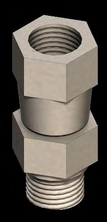
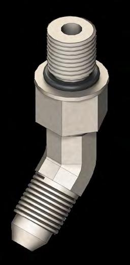
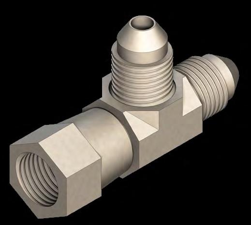
18 LEVEL-UP COMPONENTS LEVELING AND STABILIZATION AF AD AC AG AE AH AI AK AJ AL AQ AM AO AN AP AS AR Callout AC AD AE AF AG AH AI AJ AK AL AM AN AO AP AQ AR AS Rev: Part # Description Hose Union Fitting Straight Fitting JIC to O-Ring 90 Degree Elbow Fitting T-Fitting with O-Ring on Run Swivel Elbow Fitting Swivel T-Fitting 45 Degree Elbow Fitting Swivel Straight Fitting Swivel Elbow Fitting Steel Cap Fitting Long Straight Fitting Union T-Fitting Cross Fitting Hose Coupling Quick Disconnect Hex Plug Hollow Hex Plug Contact us: Lippert Components Inc Phone: (574) customerservice@lci1.com Page 18 of 22


 537-8900")
19 LEVEL-UP COMPONENTS LEVELING AND STABILIZATION AT AU AT AV AT AX AY AT AW Callout Part # Description AT Manifold AU Restricted Manifold AV Port Header Block AW Orange Hose AX Black Hose AY Position Eirc Block w/ Mounting Holes and Pass Through Rev: Contact us: Lippert Components Inc Phone: (574) customerservice@lci1.com Page 19 of 22
20 Notes Rev: Page 20 Level-Up Towable Owner's Manual
21 Notes Rev: Page 21 Level-Up Towable Owner's Manual


22 The contents of this manual are proprietary and copyright protected by Lippert Components, Inc. ( LCI ). LCI prohibits the copying or dissemination of portions of this manual unless prior written consent from an authorized LCI representative has been provided. Any unauthorized use shall void any applicable warranty. The information contained in this manual is subject to change without notice and at the sole discretion of LCI. Revised editions are available for free download from Please recycle all obsolete materials. For all concerns or questions, please contact Lippert Components, Inc. Ph: (574) Web: lci1.com customerservice@lci1.com Rev: Page 22 Level-Up Towable Owner's Manual
Level-Up With OneControl Touch Panel OWNER'S MANUAL
 Level-Up With OneControl Touch Panel OWNER'S MNUL Table of Contents System Information 2 Safety Information 3 Touch Pad Diagram - uto Leveling Control 3 Red/Green LED Indicator 3 Operation - uto Leveling
Patriot Jack Systems OWNER'S MANUAL
 Patriot Jack Systems OWNER'S MANUAL TABLE OF CONTENTS Introduction 2 Operation 3 Dual Jack Two-Valve System 3 Dual Jack One-Valve System 3 Single Jack One-Valve System 3 Preventive Maintenance 4 Adding
Level-Up LCD 5th Wheel TROUBLESHOOTING GUIDE
 Level-Up LCD 5th Wheel TROULESHOOTING GUIDE TLE OF CONTENTS Introduction 2 System and Safety Information 2 Prior to Operation 2 Components 3 5 th Wheel Operation 5 Unhitching the Trailer From Tow Vehicle
LCI4A3LCD Hydraulic Leveling
 LCI4A3LCD Hydraulic Leveling OWNER'S MANUAL with LCD Touch Pad (4-Point/3-Valve - Motorized) TABLE OF CONTENTS System Information 3 Component Description 3 Safety Information 3 Operation 4 Selecting A
Ground Control 3.0 (5th Wheel) 4 Point and 6 Point
 4 Point and 6 Point") Ground Control 3.0 (5th Wheel) 4 Point and 6 Point OEM INSTLLTION MNUL Rev: 11.13.2017 Page 1 Ground Control 3.0 5th Wheel OEM Installation Manual (2) TLE OF CONTENTS System and Safety Information 2 Preparation
Ground Control 3.0 (5th Wheel) 4 Point and 6 Point OEM INSTLLTION MNUL Rev: 11.13.2017 Page 1 Ground Control 3.0 5th Wheel OEM Installation Manual (2) TLE OF CONTENTS System and Safety Information 2 Preparation
Ground Control TT Leveling System OWNER'S MANUAL
 Ground Control TT Leveling System OWNER'S MNUL TBLE OF CONTENTS System Information 2 Features 2 Safety Information 2 Touch Pad Diagram 3 Operation 4 Basic Jack Operation 4 Unhitching From Tow Vehicle 4
ULTRA LEVEL MOTORIZED LEVELING
 ULTRA LEVEL MOTORIZED LEVELING OWNER'S MANUAL Page 1 TABLE OF CONTENTS SYSTEM 3 Prior to Operation 3 System Description 3 Features 3 Fluid Recommendation 4 Component Description 4 System Wiring Requirements
LCI Motorized Leveling - Unidirectional (2009-Present)
") LCI Motorized Leveling - Unidirectional (2009-Present) OWNER'S MANUAL Rev: 07.09.2018 LCI Motorized Leveling (2009 - Present) Owner's Manual TABLE OF CONTENTS SYSTEM 3 Prior to Operation 3 System Description
LCI Motorized Leveling - Unidirectional (2009-Present) OWNER'S MANUAL Rev: 07.09.2018 LCI Motorized Leveling (2009 - Present) Owner's Manual TABLE OF CONTENTS SYSTEM 3 Prior to Operation 3 System Description
Patriot Jack Systems OEM INSTALLATION MANUAL
 Patriot Jack Systems OEM INSTALLATION MANUAL TABLE OF CONTENTS Introduction 2 Resources Required 2 Jack, Switch Installation 3 Dual Jack Two-Valve System 4 Connect Hoses 4 Electrical Connections 4 Operation
Ground Control 3.0 (5th Wheel) 4 Point and 6 Point OneControl Touch Panel OWNER'S MANUAL
 4 Point and 6 Point OneControl Touch Panel OWNER'S MANUAL") Ground Control 3.0 (5th Wheel) 4 Point and 6 Point OneControl Touch Panel OWNER'S MNUL TBLE OF CONTENTS System Information 3 Safety Information 3 Touch Pad Diagram - uto Leveling Control Touch Pad 3 Operation
Ground Control 3.0 (5th Wheel) 4 Point and 6 Point OneControl Touch Panel OWNER'S MNUL TBLE OF CONTENTS System Information 3 Safety Information 3 Touch Pad Diagram - uto Leveling Control Touch Pad 3 Operation
Easy Approach OEM INSTALLATION MANUAL (FOREST RIVER)
") Easy pproach OEM INSTLLTION MNUL (FOREST RIVER) Introduction TBLE OF CONTENTS Introduction 2 Safety 3 Resources Required 3 Installation 4 Fully ssembled xle Sub-Frame 4 Installing the Hydraulic System
Easy pproach OEM INSTLLTION MNUL (FOREST RIVER) Introduction TBLE OF CONTENTS Introduction 2 Safety 3 Resources Required 3 Installation 4 Fully ssembled xle Sub-Frame 4 Installing the Hydraulic System
OEM INSTALLATION MANUAL
 Ground Control 3.0 (5th Wheel) 4 Point and 6 Point OEM INSTLLTION MNUL Rev: 06.15.2016 Page 1 Ground Control 3.0 5th Wheel OEM Installation Manual TLE OF CONTENTS System and Safety Information 2 Preparation
LCI Level-Up Motorhome Leveling (2013-Present) OWNER'S MANUAL. Rev: Page 1 LCILevel-Up MotorhomeLeveling (2013-Present)OwnersManual
 OWNER'S MANUAL. Rev: Page 1 LCILevel-Up MotorhomeLeveling (2013-Present)OwnersManual") LCI Level-Up Motorhome Leveling (2013-Present) OWNER'S MANUAL Rev: 05.23.2016 Page 1 LCILevel-Up MotorhomeLeveling (2013-Present)OwnersManual TABLE OF CONTENTS System Information 3 Prior To Operation 3
LCI Level-Up Motorhome Leveling (2013-Present) OWNER'S MANUAL Rev: 05.23.2016 Page 1 LCILevel-Up MotorhomeLeveling (2013-Present)OwnersManual TABLE OF CONTENTS System Information 3 Prior To Operation 3
LCI Motorized Leveling ( )
") ED U TI N LCI Motorized Leveling (2002-2008) D IS C O N OWNER'S MANUAL Rev: 12.27.2017 Page 1 LCI Motorized Leveling (02-08) Owner's Manual TABLE OF CONTENTS System 3 System Description 3 Component Description
ED U TI N LCI Motorized Leveling (2002-2008) D IS C O N OWNER'S MANUAL Rev: 12.27.2017 Page 1 LCI Motorized Leveling (02-08) Owner's Manual TABLE OF CONTENTS System 3 System Description 3 Component Description
OEM INSTALLATION MANUAL
 G C 3.0 4 P 6 P OEM INSTLLTION MNUL Rev: 03.13.2015 Page 1 Ground Control 3.0 OEM Installation Manual System and Safety Information TLE OF CONTENTS System and Safety Information 2 Preparation 2 Criteria
Level Up. Level Up Installation and Owner s Manual. Installation and Owner s Manual (For Aftermarket Applications)
") Level Up Installation and Owner s Manual (For Aftermarket Applications) THE LEVEL UP SYSTEM FOR 5TH WHEELS IS ONLY AUTHORIZED FOR INSTALLATION ON LCI BRAND FRAMES WITH AN I-BEAM OF 8 INCHES OR GREATER
Level Up Installation and Owner s Manual (For Aftermarket Applications) THE LEVEL UP SYSTEM FOR 5TH WHEELS IS ONLY AUTHORIZED FOR INSTALLATION ON LCI BRAND FRAMES WITH AN I-BEAM OF 8 INCHES OR GREATER
PSX2 (Power Stabilizing System) OWNER'S MANUAL
 OWNER'S MANUAL") PSX2 (Power Stabilizing System) OWNER'S MANUAL TABLE OF CONTENTS Safety Information 2 System Description 3 Operation 3 Preparation 3 Extending Stabilizers 4 Retracting Stabilizers 4 Stabilizing System
PSX2 (Power Stabilizing System) OWNER'S MANUAL TABLE OF CONTENTS Safety Information 2 System Description 3 Operation 3 Preparation 3 Extending Stabilizers 4 Retracting Stabilizers 4 Stabilizing System
Level Up. Level Up Installation and Owner s Manual. Installation and Owner s Manual (For Aftermarket Applications) Table of Contents
 Table of Contents") Level Up Installation and Owner s Manual (For Aftermarket Applications) The Aftermarket Level Up system can only be installed on a Lippert chassis. Table of Contents System and Safety Information... 2
Level Up Installation and Owner s Manual (For Aftermarket Applications) The Aftermarket Level Up system can only be installed on a Lippert chassis. Table of Contents System and Safety Information... 2
Level-Up Motorhome Leveling
 Level-Up Motorhome Leveling Rev: 08.06.18 Page 1 CCD-0001751 TABLE OF CONTENTS Introduction 3 Components 3 Operation 5 Selecting a Site 5 Automatic Leveling Procedure 5 Automatic Leveling Descriptive Logic
Aftermarket Manual. Aftermarket Manual. Level-Up. Table of Contents. Level-Up
 Level-Up Aftermarket Manual Table of Contents Quoting Level Up Systems.... 2 Preparation.... 2 Installation... 4 Rear Jacks... 4 Rear Sensor... 6 Front Landing Gear... 7 Power Unit... 8 Assembling and
Electric Stabilizer Jack
 Electric Stabilizer Jack OWNER'S MANUAL Rev: 10.09.2017 Page 1 Electric Stabilizer Jack Owners Manual TABLE OF CONTENTS System 2 System Description 3 Operation 3 Extending Stabilizer Jack 3 Retracting
Ground Control 3.0 Landing Gear OWNER'S MANUAL
 Ground Control 3.0 Landing Gear OWNER'S MANUAL Rev: 07.02.2018 TABLE OF CONTENTS System Information 2 Operation 2 Prior to Operation 2 Extending Landing Gear 3 Retracting Landing Gear 3 Troubleshooting
Hydro-Sync Slide-Out System
 Hydro-Sync Slide-Out System SERVICE MANUAL Rev: 08.14.2018 Hydro-Sync Slide-out System Service Manual TABLE OF CONTENTS Safety Information 3 Product Information 3 Operation 4 Extending Slide-Out Room 4
Ground Control 3.0 Landing Gear
 Ground Control 3.0 Landing Gear OEM INSTALLATION MANUAL Rev: 12.28.2017 Page 1 TABLE OF CONTENTS Safety and System Information 2 Installation 3 Landing Gear 3 Wiring Landing Gear 4 Wiring Diagram 5 Operation
Power Tongue Jack OWNER'S MANUAL
 Power Tongue Jack OWNER'S MANUAL TABLE OF CONTENTS Product Information 2 Safety 3 Operation 4 Unhitching From Tow Vehicle 4 Hitching to Tow Vehicle 4 Manual Operation 5 Troubleshooting 6 Fuse 6 Clutch
EuroLoft Bed Lift OWNER'S MANUAL
 EuroLoft Bed Lift OWNER'S MANUAL TABLE OF CONTENTS System Information 2 Safety Information 2 Important Safety Information 2 Operation 3 Prior to Operating the EuroLoft Bed Lift System 3 Lowering the Bed
SCHWINTEK TV LIFT (AUSTRALIA) INSTALLATION MANUAL
 INSTALLATION MANUAL") SCHWINTEK TV LIFT (AUSTRALIA) INSTALLATION MANUAL TABLE OF CONTENTS Safety Information 2 Resources Required 2 Schwintek TV Lift Installation 3-4 Programming the Extend and Retract Stops 5 Operation 5 Schwintek
SCHWINTEK TV LIFT (AUSTRALIA) INSTALLATION MANUAL TABLE OF CONTENTS Safety Information 2 Resources Required 2 Schwintek TV Lift Installation 3-4 Programming the Extend and Retract Stops 5 Operation 5 Schwintek
Ground Control 3.0 Landing Gear OEM INSTALLATION MANUAL
 Ground Control 3.0 Landing Gear OEM INSTALLATION MANUAL TABLE OF CONTENTS Safety and System Information 2 Installation 3 Landing Gear 3 Wiring Landing Gear 4 Wiring Diagram 5 Operation 6 Prior to Operation
In-Wall Slide-Out OWNER'S MANUAL. Rev: Page 1 In-Wall Slide-out Owner's Manual
 In-Wall Slide-Out OWNER'S MANUAL Rev: 04.12.2017 Page 1 In-Wall Slide-out Owner's Manual TABLE OF CONTENTS Safety Information 3 Operation 3 Prior To Operation 3 Extending Slide-Out Room 4 Retracting Slide-Out
Standalone Smart Jack OEM INSTALL MANUAL. Rev: Page 1 Standalone Smart Jack OEM Install Manual
 Standalone Smart Jack OEM INSTLL MNUL Rev: 09.23.2016 Page 1 Standalone Smart Jack OEM Install Manual TBLE OF CONTENTS Safety Information 2 Product Information 2 Resources Required 2 Preparation 3 Installation
Ground Control TT Leveling with LCD Touch Pad
 Ground Control TT Leveling with LCD Touch Pad OEM INSTLLTION MNUL Rev: 11.29.2018 Page 1 TLE OF CONTENTS Safety Information 3 Resources Required 3 Measuring Departure and pproach ngle 4 Installation 5
SlimRack Bed Lift System OEM INSTALLATION MANUAL
 SlimRack Bed Lift System OEM INSTALLATION MANUAL Rev: 07.11.2018 TABLE OF CONTENTS System Information 2 Safety Information 3 Resources Required 3 General Requirements 3 Installation 4 SlimRack Bed Lift
LCI4A3LCD Hydraulic Leveling (Sprinter Bolt- On Mounting Bracket) OEM INSTALLATION MANUAL
 OEM INSTALLATION MANUAL") LCI4A3LCD Hydraulic Leveling (Sprinter Bolt- On Mounting Bracket) OEM INSTALLATION MANUAL TABLE OF CONTENTS System Information 3 Component Description 3 Safety Information 4 Preparation 5 Tools Required
LCI4A3LCD Hydraulic Leveling (Sprinter Bolt- On Mounting Bracket) OEM INSTALLATION MANUAL TABLE OF CONTENTS System Information 3 Component Description 3 Safety Information 4 Preparation 5 Tools Required
X-Ramp Hydraulic Lowering System OEM INSTALLATION MANUAL
 X-Ramp Hydraulic Lowering System OEM INSTLLTION MNUL TBLE OF CONTENTS Introduction 2 Safety Requirements 2 Resources Required 3 Preparation 3 Installation 3 Fully ssembled xle Sub-Frame 3 Welding xle Sub-Frame
HYDRAULIC LEVELING SYSTEMS OPERATIONS MANUAL
 HYDRAULIC LEVELING SYSTEMS OPERATIONS MANUAL (For systems with touch pad part number 500675) touchpad 500675 82-L0140-00 REV.3 WARNING DO NOT USE THE POWER GEAR HYDRAULIC LEVELING SYSTEM (OR AIR SUSPENSION)
PSX2 (Power Stabilizing System) OEM INSTALLATION MANUAL
 OEM INSTALLATION MANUAL") PSX2 (Power Stabilizing System) OEM INSTLLTION MNUL Rev: 10.24.2018 PSX2 OEM TLE OF CONTENTS Safety Information 2 System Description 3 Installation 3 Resources Required 3 Determine Stabilizer Locations
PSX2 (Power Stabilizing System) OEM INSTLLTION MNUL Rev: 10.24.2018 PSX2 OEM TLE OF CONTENTS Safety Information 2 System Description 3 Installation 3 Resources Required 3 Determine Stabilizer Locations
Electric Through Frame Slide-Out
 Electric Through Frame Slide-Out OWNER'S MANUAL Rev: 11.13.2017 Page 1 Electric Through Frame Slide-out Owner's Manual TABLE OF CONTENTS Warning, Safety, and System Requirement Information 2 Description
Flip Automatic Jack Foot
 Flip Automatic Jack Foot OEM INSTALLATION MANUAL Rev: 12.28.2017 Page 1 Flip Automatic Jack Foot OEM Installation Manual TABLE OF CONTENTS System Information 2 Safety Information 2 Resources Required 2
Class C Hydraulic Leveling System OEM INSTALLATION MANUAL
 Class C Hydraulic Leveling System OEM INSTALLATION MANUAL TABLE OF CONTENTS System Information 3 Component Description 3 Safety Information 3 Prior to Operation 4 Preparation 4 Installation 5 Prior to
OPERATORS MANUAL for AUTOMATIC RV SYSTEM. Comment [KO1]:
![OPERATORS MANUAL for AUTOMATIC RV SYSTEM. Comment [KO1]:](/thumbs/80/81800064.jpg "OPERATORS MANUAL for AUTOMATIC RV SYSTEM. Comment [KO1]:") OPERATORS MANUAL for AUTOMATIC RV SYSTEM Comment [KO1]: 82 L0130 00 Rev. 2 July 2003 TABLE OF CONTENTS OPERATION AND MAINTENANCE...1 OPERATION CAUTION NOTES...1 BEFORE YOU OPERATE THE SYSTEM...2 SELECTING
OPERATORS MANUAL for AUTOMATIC RV SYSTEM Comment [KO1]: 82 L0130 00 Rev. 2 July 2003 TABLE OF CONTENTS OPERATION AND MAINTENANCE...1 OPERATION CAUTION NOTES...1 BEFORE YOU OPERATE THE SYSTEM...2 SELECTING
Aftermarket Manual. Aftermarket Manual. Table Of Contents. Ground Control 3.0
 ftermarket Manual Ground Control 3.0 ftermarket Manual Table Of Contents Introduction................................... 2 Fully utomatic Electric Leveling System 2 Quick Facts 2 Parts List......................................
In-Wall Slide-Out (Winnebago Version) OWNER'S MANUAL
 OWNER'S MANUAL") In-Wall Slide-Out (Winnebago Version) OWNER'S MANUAL TABLE OF CONTENTS System and Safety Information 2 Safety Information 2 Operation 3 Prior to Operation 3 Extending Slide-out Room 3 Retracting Slide-out
In-Wall Slide-Out (Winnebago Version) OWNER'S MANUAL TABLE OF CONTENTS System and Safety Information 2 Safety Information 2 Operation 3 Prior to Operation 3 Extending Slide-out Room 3 Retracting Slide-out
Class C Hydraulic Leveling System OEM INSTALLATION MANUAL
 Class C Hydraulic Leveling System OEM INSTALLATION MANUAL TABLE OF CONTENTS System Information 3 Component Description 3 Safety Information 3 Prior to Operation 4 Preparation 4 Installation 5 Prior to
HYDRAULIC LANDING GEAR REPLACEMENT
 Purpose This kit outlines the procedure to replace existing square hydraulic landing gear jacks, including square and round hydraulic, pin-less jacks. Square landing gear is no longer available. Required
Coachstep OWNER'S MANUAL
 Coachstep OWNER'S MANUAL TABLE OF CONTENTS System and Safety Information 3 Operation 4 Maintenance 4 How to Adjust Cams 4 Lubrication 4 Coachstep Gear Plate and Bolt Replacement 5 Coachstep Motor Replacement
Hitch Receiver OEM INSTALLATION MANUAL
 Hitch Receiver OEM INSTALLATION MANUAL TABLE OF CONTENTS Introduction 2 Safety 3 Resources Required 3 Installation 4 2" and 2 1/2" Accessory Hitch Receiver 4 Bike Rack /Accessory Hitch Receiver 6 Boat
EuroLoft Bed Lift OWNER'S MANUAL
 EuroLoft Bed Lift OWNER'S MANUAL TABLE OF CONTENTS System Information 2 Safety Information 2 Important Safety Information 2 Operation 3 Prior to Operating the EuroLoft Bed Lift System 3 Lowering the Bed
Ground Control and 6 Point OneControl Touch Panel
 Ground Control 3.0 4 and 6 Point OneControl Touch Panel OEM INSTLLTION MNUL (For systems installed after June 1, 2018) TLE OF CONTENTS System Information 3 Safety Information 3 Resources Required 3 Preparation
LIPPERTCOMPONENTS, INC. HYDRAULIC SLIDEOUT AND HYDRAULIC LANDING GEAR (HLG) SYSTEM OPERATION AND SERVICE MANUAL
 SYSTEM OPERATION AND SERVICE MANUAL") LIPPERTCOMPONENTS, INC. HYDRAULIC SLIDEOUT AND HYDRAULIC LANDING GEAR (HLG) SYSTEM OPERATION AND SERVICE MANUAL TABLE OF CONTENTS SYSTEM...... Warning...... Prior to Operation... Description..... Preventative
LIPPERTCOMPONENTS, INC. HYDRAULIC SLIDEOUT AND HYDRAULIC LANDING GEAR (HLG) SYSTEM OPERATION AND SERVICE MANUAL TABLE OF CONTENTS SYSTEM...... Warning...... Prior to Operation... Description..... Preventative
SlimRack Bed Lift System OWNER'S MANUAL
 SlimRack Bed Lift System OWNER'S MANUAL TABLE OF CONTENTS System Information 2 Features 2 Operation 3 Prior to Operating the SlimRack Bed Lift System 3 Raising the Bed 3 Lowering the Bed 3 Troubleshooting
Sway Command Tow Control System OWNER'S MANUAL
 Sway Command Tow Control System OWNER'S MANUAL TABLE OF CONTENTS System Components 2 Introduction 3 Causes of Sway 3 Prior to Operation 3 Sway Command Controller Operation 4 Light Codes and Troubleshooting
Tire Linc OEM INSTALLATION MANUAL
 Tire Linc OEM INSTLLTION MNUL Introduction The Tire Linc tire pressure monitoring system is a wireless system that automatically monitors tire pressure and temperature. If any abnormalities are detected,
G C G III. OE Installation Manual
 G C G III OE Installation Manual 2 Table of Contents Installing Rear Jacks/Sensor 3 Installing Control Module/Interface 4 Programming the System 5 Parts Diagram and BOM 6 Wiring Diagram 7 NOTE: The front
Embedded Rack Slide-out System
 Embedded Rack Slide-out System SERVICE MANUAL Rev: 02.16.2017 Page 1 Electric Embedded Rack Slide-out System TABLE OF CONTENTS Safety Information 3 Product Information 3 Operation 4 Extending Slide-Out
Equa-Flex Tandem and Triple OEM INSTALLATION MANUAL
 Equa-Flex Tandem and Triple OEM INSTALLATION MANUAL TABLE OF CONTENTS System Information 2 Tandem Axle Options 2 Triple Axle Options 2 Safety Information 2 Resources Required 3 Installation 3 Tandem Axle
LIPPERTCOMPONENTS 5TH WHEEL HYDRAULIC SLIDEOUT AND LANDING GEAR (HLG) SYSTEM OPERATION AND SERVICE MANUAL
 SYSTEM OPERATION AND SERVICE MANUAL") LIPPERTCOMPONENTS 5TH WHEEL HYDRAULIC SLIDEOUT AND LANDING GEAR (HLG) SYSTEM OPERATION AND SERVICE MANUAL TABLE OF CONTENTS SYSTEM...... Warning...... Prior to Operation... Description..... Preventative
LIPPERTCOMPONENTS 5TH WHEEL HYDRAULIC SLIDEOUT AND LANDING GEAR (HLG) SYSTEM OPERATION AND SERVICE MANUAL TABLE OF CONTENTS SYSTEM...... Warning...... Prior to Operation... Description..... Preventative
HYDRAULIC LEVELING SYSTEMS OPERATIONS MANUAL (For systems with touch pad part number , , , , or no number at all)
") HYDRAULIC LEVELING SYSTEMS OPERATIONS MANUAL (For systems with touch pad part number 500089, 500105, 500210, 500456, 500535 or no number at all) Visit us on the web at www.lci1.com 82-L0040-01 Rev. 1 WARNING
HYDRAULIC LEVELING SYSTEMS OPERATIONS MANUAL (For systems with touch pad part number 500089, 500105, 500210, 500456, 500535 or no number at all) Visit us on the web at www.lci1.com 82-L0040-01 Rev. 1 WARNING
Intelli-view Tank Monitor
 Intelli-view Tank Monitor INSTALLATION MANUAL Rev: 02.17.2017 Page 1 Intelliview Tank Monitor Install Manual TABLE OF CONTENTS System 2 Safety Information 2 Intelli-view Tank Monitor Panel Installation
Lexington L-Shaped Expandable Lounge OWNER'S MANUAL
 Lexington L-Shaped Expandable Lounge OWNER'S MANUAL TABLE OF CONTENTS Introduction 2 Safety 2 Operation 2 Expanding L-Lounge 2 Retracting L-Lounge 5 Notes 9 Introduction This owner's manual describes the
F.A.S.T. Track Flush Floor Slide-out. (Fast Assembly Self Tensioning) OWNER'S MANUAL
 OWNER'S MANUAL") F..S.T. (Fast ssembly Self Tensioning) Track Flush Floor Slide-out OWNER'S MNUL TBLE OF CONTENTS System Information 2 Major Components 2 Safety Information 3 Prior to Operation 3 Operation 4 Extending
F..S.T. (Fast ssembly Self Tensioning) Track Flush Floor Slide-out OWNER'S MNUL TBLE OF CONTENTS System Information 2 Major Components 2 Safety Information 3 Prior to Operation 3 Operation 4 Extending
Kwikee Revolution Step Series
 Kwikee Revolution Step Series OWNER'S MANUAL (3010002262) Rev: 07.26.2018 Kwikee Revolution Step Series Owner's Manual 3010002262 TABLE OF CONTENTS Safety Information 2 Product Information 2 General Service
DISCONTINUED. OPERATORS MANUAL for SEMI AUTOMATIC RV SYSTEM. 82 L Rev. 0 September 3, Comment [KO1]:
![DISCONTINUED. OPERATORS MANUAL for SEMI AUTOMATIC RV SYSTEM. 82 L Rev. 0 September 3, Comment [KO1]:](/thumbs/86/93070832.jpg "DISCONTINUED. OPERATORS MANUAL for SEMI AUTOMATIC RV SYSTEM. 82 L Rev. 0 September 3, Comment [KO1]:") OPERATORS MANUAL for SEMI AUTOMATIC RV SYSTEM 82 L0100 00 Rev. 0 September 3, 1999 Comment [KO1]: TABLE OF CONTENTS OPERATION AND MAINTENANCE...1 OPERATION CAUTION NOTES...1 BEFORE YOU OPERATE THE SYSTEM...2
OPERATORS MANUAL for SEMI AUTOMATIC RV SYSTEM 82 L0100 00 Rev. 0 September 3, 1999 Comment [KO1]: TABLE OF CONTENTS OPERATION AND MAINTENANCE...1 OPERATION CAUTION NOTES...1 BEFORE YOU OPERATE THE SYSTEM...2
DISCONTINUED. OPERATORS MANUAL for SEMI AUTOMATIC RV SYSTEM. 82 L Rev. 0. Comment [KO1]:
![DISCONTINUED. OPERATORS MANUAL for SEMI AUTOMATIC RV SYSTEM. 82 L Rev. 0. Comment [KO1]:](/thumbs/89/97984779.jpg "DISCONTINUED. OPERATORS MANUAL for SEMI AUTOMATIC RV SYSTEM. 82 L Rev. 0. Comment [KO1]:") OPERATORS MANUAL for SEMI AUTOMATIC RV SYSTEM 82 L0020 00 Rev. 0 Comment [KO1]: TABLE OF CONTENTS OPERATION AND MAINTENANCE...1 OPERATION CAUTION NOTES...1 BEFORE YOU OPERATE THE SYSTEM...2 EXCESS SLOPE...2
OPERATORS MANUAL for SEMI AUTOMATIC RV SYSTEM 82 L0020 00 Rev. 0 Comment [KO1]: TABLE OF CONTENTS OPERATION AND MAINTENANCE...1 OPERATION CAUTION NOTES...1 BEFORE YOU OPERATE THE SYSTEM...2 EXCESS SLOPE...2
OPERATORS AND SERVICE MANUAL for SEMI AUTOMATIC RV SYSTEM. Comment [KO1]:
![OPERATORS AND SERVICE MANUAL for SEMI AUTOMATIC RV SYSTEM. Comment [KO1]:](/thumbs/94/119004342.jpg "OPERATORS AND SERVICE MANUAL for SEMI AUTOMATIC RV SYSTEM. Comment [KO1]:") OPERATORS AND SERVICE MANUAL for SEMI AUTOMATIC RV SYSTEM Comment [KO1]: 82 L0331 Rev. 1 July 2003 TABLE OF CONTENTS OPERATION AND MAINTENANCE...1 OPERATION CAUTION NOTES...1 BEFORE YOU OPERATE THE SYSTEM...2
OPERATORS AND SERVICE MANUAL for SEMI AUTOMATIC RV SYSTEM Comment [KO1]: 82 L0331 Rev. 1 July 2003 TABLE OF CONTENTS OPERATION AND MAINTENANCE...1 OPERATION CAUTION NOTES...1 BEFORE YOU OPERATE THE SYSTEM...2
Sway Command Tow Control System (For Travel Trailer) OEM INSTALL MANUAL. Rev: Page 1 Sway Command OEM Install Manual
 OEM INSTALL MANUAL. Rev: Page 1 Sway Command OEM Install Manual") Sway Command Tow Control System (For Travel Trailer) OEM INSTLL MNUL Rev: 09.17.2015 Page 1 Sway Command OEM Install Manual TBLE OF CONTENTS Introduction 2 Causes of Sway 2 Preparation 3 Tools and Hardware
Sway Command Tow Control System (For Travel Trailer) OEM INSTLL MNUL Rev: 09.17.2015 Page 1 Sway Command OEM Install Manual TBLE OF CONTENTS Introduction 2 Causes of Sway 2 Preparation 3 Tools and Hardware
OPERATORS MANUAL for MANUAL RV LEVELING SYSTEM. Comment [KO1]:
![OPERATORS MANUAL for MANUAL RV LEVELING SYSTEM. Comment [KO1]:](/thumbs/80/81800032.jpg "OPERATORS MANUAL for MANUAL RV LEVELING SYSTEM. Comment [KO1]:") OPERATORS MANUAL for MANUAL RV LEVELING SYSTEM Comment [KO1]: 82 L0356 Rev. 0 June 2003 TABLE OF CONTENTS OPERATION AND MAINTENANCE...1 OPERATION CAUTION NOTES...1 BEFORE YOU OPERATE THE SYSTEM...2 SELECTING
OPERATORS MANUAL for MANUAL RV LEVELING SYSTEM Comment [KO1]: 82 L0356 Rev. 0 June 2003 TABLE OF CONTENTS OPERATION AND MAINTENANCE...1 OPERATION CAUTION NOTES...1 BEFORE YOU OPERATE THE SYSTEM...2 SELECTING
F.A.S.T. Ramp Rear Door SERVICE MANUAL
 F..S.T. Ramp Rear Door SERVICE MNUL TBLE OF CONTENTS Introduction 2 Safety Information 2 Resources Required 3 Operation 3 Removing Old Cable 3 Inserting New Cable 5 Notes 7 Introduction The following information
Kwikee Platinum Series OWNER'S MANUAL
 Kwikee Platinum Series OWNER'S MANUAL TABLE OF CONTENTS Safety Information 2 Product Information 2 General Service Notes 3 Prior To Operation 3 Operation 4 Step with Control Unit 4 Troubleshooting 5 Step
Triple Play Ramp Door OWNER'S MANUAL
 Triple Play Ramp Door OWNER'S MANUAL TABLE OF CONTENTS Introduction 2 Safety Information 3 Operation 4 To Operate the Triple Play Ramp Door Touchpad: 5 Patio Mode 5 Ramp Mode 5 Closing the Triple Play
Hydraulic Through Frame Slide-out SERVICE MANUAL
 Hydraulic Through Frame Slide-out SERVICE MNUL TBLE OF CONTENTS Warning, Safety, and System Requirement Information 3 Description 3 Safety Information 3 Prior to Operation 4 Operation 4 Extending Slide-Out
OPERATION MANUAL for MANUAL LEVELING SYSTEMS with square foot pads on jacks
 OPERATION MANUAL for MANUAL LEVELING SYSTEMS with square foot pads on jacks Dewald manual system touchpad #140-1179 Visit us on the web at www.powergearus.com 82-L0377 REV.0B 2 TABLE OF CONTENTS Page 3:
5th Wheel Electric Leveling System
 LEVELING SYSTEM MADE IN USA MADE IN U.S.A. R V PR ODUC T S NORCO INDUSTRIES, INC. 5th Wheel Electric Leveling System 20300513 TABLE OF CONTENTS...2 STANDARD PROCEDURES & AUTOMATED FUNCTIONS...3 UNIT DETACHMENT
Sway Command Tow Control System
 Sway Command Tow Control System (For Travel Trailer) OEM INSTLLTION MNUL TBLE OF CONTENTS Introduction 2 Causes of Sway 2 Preparation (Non-Prepped Trailer) 3 Resources Required 3 Components Required 3
Kwikee IMGL Step Control Testing Procedure #82-ST0500
 Kwikee IMGL Step Control Testing Procedure #82-ST0500 TABLE OF CONTENTS Introduction 2 Resources Required 2 General Service Notes 3 Preparation 5 Troubleshooting and Test Procedures 5 Testing the Step
Kwikee # Series Step OWNER'S MANUAL ( )
") Kwikee #842 42 Series Step OWNER'S MANUAL (1422258) TABLE OF CONTENTS Safety Information 2 Product Information 3 Step with Control Unit 3 Operation 3 General Service 4 Prior To Operation 4 Adjusting Cam
Kwikee #842 42 Series Step OWNER'S MANUAL (1422258) TABLE OF CONTENTS Safety Information 2 Product Information 3 Step with Control Unit 3 Operation 3 General Service 4 Prior To Operation 4 Adjusting Cam
In-Wall Slide-out COMPONENT ASSEMBLY MANUAL
 In-Wall Slide-out COMPONENT SSEMLY MNUL TLE OF CONTENTS System Information 2 Safety Information 2 Resources Required 2 Motor Removal 2 Timing Procedure 3 Installing Shipping ngles 4 Notes 5 System Information
Compact Triple Electric Step OWNERS MANUAL
 Compact Triple Electric Step OWNERS MANUAL TABLE OF CONTENTS Safety Information 2 Product Information 3 Operation 3 Installation 3 Removal of Existing Step 3 Extending Step Assembly 3 Wiring the Step 4
KWIKEE #888 ELECTRIC STEP. Owner's Manual ( )
") KWIKEE #888 ELECTRIC STEP Owner's Manual (1422279) TABLE OF CONTENTS Safety Information 2 Motor Assembly Identification 3 Product Information 4 Steps With Control Unit 4 Steps Without Control Unit 4 General
KWIKEE #888 ELECTRIC STEP Owner's Manual (1422279) TABLE OF CONTENTS Safety Information 2 Motor Assembly Identification 3 Product Information 4 Steps With Control Unit 4 Steps Without Control Unit 4 General
Turning Point Pin Box. by Trailair OWNER'S MANUAL
 Turning Point Pin Box by Trailair OWNER'S MANUAL TABLE OF CONTENTS Product and Safety Information 2 Preparation 3 Tow Rating Weights Check For 10,000 lbs Pin Box (Fig. 1) 3 Tow Rating Weights Check For
DISCONTINUED. OPERATORS MANUAL for MANUAL RV SYSTEM REV. 1 August, Comment [KO1]:
![DISCONTINUED. OPERATORS MANUAL for MANUAL RV SYSTEM REV. 1 August, Comment [KO1]:](/thumbs/92/110074047.jpg "DISCONTINUED. OPERATORS MANUAL for MANUAL RV SYSTEM REV. 1 August, Comment [KO1]:") OPERATORS MANUAL for MANUAL RV SYSTEM 81 1297 REV. 1 August, 1997 Comment [KO1]: TABLE OF CONTENTS OPERATION AND MAINTENANCE... 1 LEVELING PROCEDURES...2 RETRACTION PROCEDURES...3 RECOMMENDED FLUIDS...3
OPERATORS MANUAL for MANUAL RV SYSTEM 81 1297 REV. 1 August, 1997 Comment [KO1]: TABLE OF CONTENTS OPERATION AND MAINTENANCE... 1 LEVELING PROCEDURES...2 RETRACTION PROCEDURES...3 RECOMMENDED FLUIDS...3
PARTS AND SERVICE MANUAL FOR LEVELING SYSTEMS WITH TOUCH PAD PART NUMBERS , , , , or no number at all
 PARTS AND SERVICE MANUAL FOR LEVELING SYSTEMS WITH TOUCH PAD PART NUMBERS 500089, 500105, 500210, 500456, 500535 or no number at all Visit us on the web at www.powergearus.com! 82 L0051 00 Rev. 3 1 WARNING
Solera Power Awning TROUBLESHOOTING AND SERVICE MANUAL
 Solera Power Awning TROUBLESHOOTING AND SERVICE MANUAL Table of Contents System and Safety Information 2 Basic Troubleshooting 3 Service and Replacement 4 Support Arm Assembly Replacement 4 Changing (Remove
OEM INSTALLATION MANUAL
 Waste Master OEM INSTALLATION MANUAL Rev: 09.04.2015 Page 1 Waste Master Installation Manual TABLE OF CONTENTS Introduction 2 Installation of System 3 Prior To Storage Box Installation 4 Storage Box Installation
Road Armor Triple Axle Equalizer by Trailair
 Road Armor Triple Axle by Trailair OEM INSTALLATION MANUAL Rev: 06.26.2017 Page 1 TABLE OF CONTENTS System Information 2 Triple Axle Options 2 Safety Information 2 Resources Required 2 Installation 3 Rear
SlimRack Slide-out COMPONENTS ASSEMBLY MANUAL. Rev: Page 1 SlimRack Components Assembly Manual
 SlimRack Slide-out COMPONENTS ASSEMBLY MANUAL Rev: 11.16.2017 Page 1 SlimRack Components Assembly Manual TABLE OF CONTENTS Product Information 2 Additional Warranty Exclusions 2 Safety Information 2 Resources
Schwintek Bunk Lift INSTALLATION MANUAL. Rev: Page 1 Schwintek Bunk Lift OEM Installation Manual
 Schwintek Bunk Lift INSTALLATION MANUAL Rev: 02.03.2017 Page 1 Schwintek Bunk Lift OEM Installation Manual TABLE OF CONTENTS Introduction 3 Required Components 3 Important Notes 3 Installation 4 Bearing
HYDRAULIC LEVELING SYSTEMS OPERATIONS MANUAL (For systems with touch pad part number , , , , or no number at all)
") HYDRAULIC LEVELING SYSTEMS OPERATIONS MANUAL (For systems with touch pad part number 500089, 500105, 500210, 500456, 500535 or no number at all) Visit us on the web at www.powergearus.com 82-L0040-01 Rev.
HYDRAULIC LEVELING SYSTEMS OPERATIONS MANUAL (For systems with touch pad part number 500089, 500105, 500210, 500456, 500535 or no number at all) Visit us on the web at www.powergearus.com 82-L0040-01 Rev.
Triple Play Ramp Door OEM INSTALLATION MANUAL
 Triple Play Ramp Door OEM INSTLLTION MNUL TLE OF CONTENTS Introduction 2 Safety Information 3 Resources Required 3 Installation 4 Doorjamb 4 Hidden Hinge Installation 7 Door Cable System 8 Electrical Connections
Bauer NE Lock OWNER'S MANUAL
 Bauer NE Lock OWNER'S MNUL TBLE OF CONTENTS Product Information 2 Features 2 Operation 3 Calibration and Programming 3 Preset Factory Code 3 Programming New Code 3 Maintenance 3 Installation 4 Bauer NE
IMGL and 9510 Control Replacement Kit #214 INSTALLATION MANUAL
 IMGL and 9510 Control Replacement Kit #214 INSTALLATION MANUAL TABLE OF CONTENTS Safety Information 2 Product Information 2 Removal and Replacement of IMGL Assembly 4 Removal and Replacement of The Control
Trailer Axle Beam Replacement SERVICE MANUAL
 Trailer Axle Beam Replacement SERVICE MANUAL September 20, 2017 Trailer Axle Beam Service Manual TABLE OF CONTENTS System Information 2 Safety Information 2 Required Resources 2 Hub Removal 3 Axle Beam
Self-Deploying Rail Kit OEM INSTALLATION MANUAL
 Self-Deploying Rail Kit OEM INSTLLTION MNUL TLE OF ONTENTS Introduction 2 Safety Information 2 Resources Required 3 Prior to Installation 3 Installation 3 Doorjamb 3 Setting the Doorjamb 3 inch Latch 4
Ice House Axle OEM INSTALLATION MANUAL
 Ice House xle OEM INSTLLTION MNUL TLE OF CONTENTS System Information 2 Tools required 2 Hardware Required 2 Grease Specifications 2 Prior to Installation 3 Installation 4 Maintenance Schedule 8 Notes 9
# & Automatic Touchpad. # & Semi-Auto Touchpad. # Manual Touchpad
 # 500629 & 140-1226 Automatic Touchpad # 500675 & 140-1231 Semi-Auto Touchpad # 500731 Manual Touchpad Parts and Service Manual for Hydraulic Leveling Systems with Touch Pad Part Numbers 500675, 140-1231,
PowerLevel s e r i e s
 Owner s Manual Hydraulic Leveling CONTENTS Introduction Operation Control Panel Automatic Leveling Manual Leveling Retracting Jacks Remote Operation Care & Maintenance Troubleshooting Error Codes 1 2 2
LC I LIPPERT COMPONENTS HYDRAULIC FULL WALL SLIDEOUT SYSTEM OPERATION AND SERVICE MANUAL
 LC I LIPPERT COMPONENTS HYDRAULIC FULL WALL SLIDEOUT SYSTEM OPERATION AND SERVICE MANUAL TABLE OF CONTENTS SYSTEM...... 3 Warning...... 3 Description..... 3 Prior to Operation... 4 4 OPERATION... Main
OPERATORS MANUAL for MANUAL RV LEVELING SYSTEM. Comment [KO1]:
![OPERATORS MANUAL for MANUAL RV LEVELING SYSTEM. Comment [KO1]:](/thumbs/88/117097014.jpg "OPERATORS MANUAL for MANUAL RV LEVELING SYSTEM. Comment [KO1]:") OPERATORS MANUAL for MANUAL RV LEVELING SYSTEM Comment [KO1]: 82 L0356 Rev. 0 June 2003 TABLE OF CONTENTS OPERATION AND MAINTENANCE...1 OPERATION CAUTION NOTES...1 BEFORE YOU OPERATE THE SYSTEM...2 SELECTING
OPERATORS MANUAL for MANUAL RV LEVELING SYSTEM Comment [KO1]: 82 L0356 Rev. 0 June 2003 TABLE OF CONTENTS OPERATION AND MAINTENANCE...1 OPERATION CAUTION NOTES...1 BEFORE YOU OPERATE THE SYSTEM...2 SELECTING
HYDRAULIC SLIDEOUT SYSTEM OPERATION AND SERVICE MANUAL
 HYDRAULIC SLIDEOUT SYSTEM OPERATION AND SERVICE MANUAL TABLE OF CONTENTS SYSTEM...... Warning...... Description..... Prior to Operation... Preventative Maintenance..... OPERATION... Warning... Extending
Operator s Manual. Automatic Electric Jack Leveling. The leveling system shall only be operated under the following conditions:
 Operator s Manual with Automatic Leveling Touchpad #140-1226 Control Box #140-1224 co Copyright PowerGear 1/07 #82-L0368 Rev. 0D Contents Before You Level Your Coach 1 Caution 1 Leveling System Operating
Waste Master OWNER'S MANUAL. Rev: Page 1 Waste Master Owner's Manual
 Waste Master OWNER'S MANUAL Rev: 06.15.2015 Page 1 Waste Master Owner's Manual TABLE OF CONTENTS Introduction 2 Operation 3 Service 4 Removing The Hose Assembly 4 Field Changing Of Waste Master Nozzle