Types. Fixed-mounted circuitbreaker. NXPLUS C is a factoryassembled,
|
|
|
- Patience Henderson
- 6 years ago
- Views:
Transcription
1


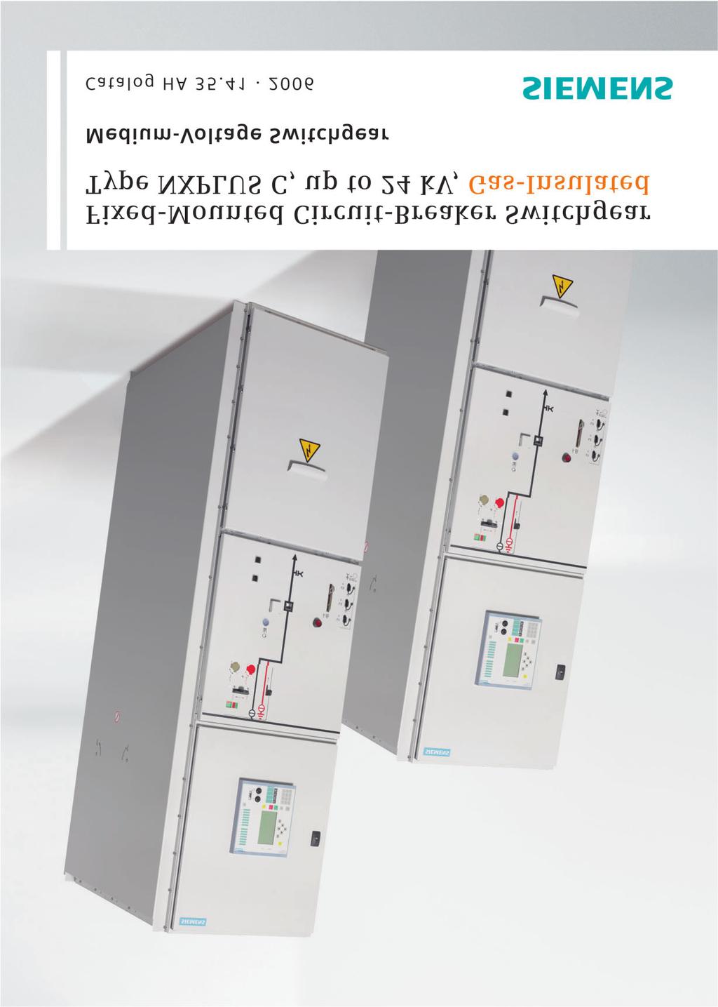
2 R-HA5-05a eps Fixed-Mounted Circuit-Breaker Switchgear Type NXPLUS C, up to kv, Gas-Insulated Contents Application Page Types Application Types, typical uses, ratings to Requirements Features, safety, technology and 5 Technical Data Electrical data 6 and 7 Room planning 8 Shipping data, classification 9 Dimensions Front views, sections, flo openings, fixing points 0 to 6 Product Range Single-busbar panels 7 to 9 Double-busbar panels 0 Design Basic panel design Components Vacuum circuit-breaker and Three-position switch and 5 HV HRC fuse assembly 6 and 7 Vacuum contact, mot protection 8 Busbars 9 Current and voltage transfmers 0 and Panel connection to 5 Indicating and measuring equipment 6 to 9 Standards Standards, specifications, guidelines 0 and Fixed-mounted circuitbreaker switchgear NXPLUS C is a factyassembled, type-tested, metal-enclosed, metal-clad, SF 6 -insulated switchgear f single-busbar and double-busbar applications f indo installation. Circuit-breaker panel (example) Siemens AG 006 Siemens HA

3 R-HA5-07.eps R-HA5-.eps R-HA5-06.eps R-HA5-.tif Fixed-Mounted Circuit-Breaker Switchgear Type NXPLUS C, up to kv, Gas-Insulated Application Typical uses Application: Public power supply system R-HA5-09.eps Application: Industry NXPLUS C switchgear 0 kv (example) Application: Industry and offshe Siemens HA
4 Fixed-Mounted Circuit-Breaker Switchgear Type NXPLUS C, up to kv, Gas-Insulated Application Requirements Typical uses, ratings Fixed-mounted circuit-breaker switchgear NXPLUS C is used in transfmer and switching substations, e.g., in: Power supply companies Power stations Cement industry Automobile industry Iron and steel wks Rolling mills Mining industry Textile, paper and food industries Chemical industry Petroleum industry Pipeline installations Offshe installations Electrochemical plants Petrochemical plants Shipbuilding industry Diesel power plants Emergency power supply installations Lignite open-cast mines Traction power supply systems Electrical data (maximum values) and dimensions Rated voltage kv Rated frequency Hz 50/60 50/60 50/60 50/60 50/60 Rated sht-duration powerfrequency kv 0 8 ) withstand voltage Rated lightning impulse kv ) withstand voltage Ratedpeakwithstandcurrent ka Rated sht-circuit making ka current Rated sht-time ka withstand current s Rated sht-circuit breaking current ka Rated nmal current of busbar A Rated nmal current of feeders A Width mm ) ) ) ) ) Depth without pressure reliefductattherear with pressure reliefductattherear mm mm Height mm Features Environmental independence Welded switchgear vessels made of stainless steel without seals make NXPLUS C switchgear Insensitive to aggressive ambient conditions, such as Salt water Air humidity Dust Temperature Hermetically tight to ingress of feign bodies, such as Dust Dirt Small animals Independent of site altitude Compact design Thanks to the SF 6 -insulation, compact dimensions are possible Thus, Existing switchgear rooms can be used effectively New constructions cost little Costly city-area space is saved Maintenance-free design Switchgear vessels designed as sealed pressure systems, maintenance-free switching devices and enclosed cable plugs ensure Maximized power supply reliability Personnel safety Sealed-f-life design accding to IEC (sealed pressure system) Installation, operation, extension and replacement without SF 6 -gas wk Reduced operating costs Cost-efficient investment No maintenance cycles Innovations The use of digital secondary systems and combined protection and control devices ensures Clear integration in process control systems Flexible and highly simplified adaptation to new system conditions and thus to cost-efficient operation ) kv/95 kv accding to some national requirements ) 00 mm f rated nmal feeder currents of 000 A, 00 A and 500 A Siemens HA
5 Fixed-Mounted Circuit-Breaker Switchgear Type NXPLUS C, up to kv, Gas-Insulated Requirements Safety Technology Personal safety Safe-to-touch and hermetically sealed primary enclosure Cable terminations, busbars and voltage transfmers are surrounded by earthed layers All high-voltage parts including the cable terminations, busbars and voltage transfmers are metal enclosed Capacitive voltage detection system f verification of safe isolation from supply Operating mechanisms and auxiliary switches safely accessible outside the primary enclosure (switchgear vessel) Due to design an operation is only possible with closed enclosure Standard degree of protection IP 65 f all high-voltage parts of the primary circuit, IP XD f the switchgear enclosure accding to IEC and VDE 070- High resistance to internal arcs by logical mechanical interlocks and tested switchgear enclosure Arc-fault tested panels up to.5 ka Logical mechanical interlocks prevent maloperation Make-proof earthing by means of the vacuum circuitbreaker Security of operation Hermetically sealed primary enclosure independent of environmental effects (dirt, moisture and small animals) Maintenance-free in an indo environment (IEC and VDE ) Operating mechanisms of switching devices accessible outside the primary enclosure (switchgear vessel) Metal-coated, plug-in inductive voltage transfmers mounted outside the gas compartments Ring-ce current transfmers mounted outside the gas compartments Complete logical mechanical interlocking system Welded switchgear vessels, sealed f life Minimum fire load Type and routine-tested Standardized, NC production processes Quality assurance in accdance with DIN EN ISO 900 Me than 00,000 switchgear panels of Siemens in operation wldwide f many years Option: Aseismic design Reliability Type and routine-tested Standardized, NC production processes Quality assurance in accdance with DIN EN ISO 900 Me than 00,000 switchgear panels of Siemens in operation wldwide f many years General Three-pole enclosure of the primary part consisting of a switchgear vessel made of stainless steel Insulating gas SF 6 Three-position switch as busbar disconnect and feeder earthing switch Make-proof earthing by means of the vacuum circuitbreaker Compact dimensions due to SF 6 -insulation Hermetically welded switchgear vessel made of stainless steel without seals Single-pole, solid-insulated, screened busbars, plug-in type Cable connection with outside-cone plug-in system, f connection of solid-insulated bars Wall-standing free-standing arrangement Cable connection access from front Option: Cable connection access from rear (only circuitbreaker panel 50 A) Installation and extension of existing switchgear on both sides without gas wk and without modification of existing panels Interlocks Accding to IEC and VDE Logical mechanical interlocks prevent maloperation Three-position disconnect can only be operated with circuit-breaker in OPEN position Circuit-breakercontact can only be operated with three-position switch in end position and operating lever removed Switch-disconnect, contact, ring-main and metering panels are not interlocked due to their own switching capacity Three-position disconnect interlocked against the circuit-breaker in circuit-breaker panels and in bus sectionalizers with one panel width Locking device f feeder Locking device f threeposition switch Cable compartment cover (access to HV HRC fuses) always interlocked against the three-position switchdisconnect in panels with HV HRC fuses (switch-disconnect panel, metering panel and contact panel with fuses) Option: Cable compartment cover interlocked against the three-position switch (circuitbreaker panel, disconnect panel, contact panel without fuses, ring-main panel) Option: Electromagnetic interlocks Option: Actuating openings canbelockedwithpadlocks Option: Locking device f feeder earthed Modular design Panel replacement possible without SF 6 -gas wk Low-voltage compartment can be removed, plug-in bus wires Transfmers Current transfmers not subjected to dielectric stress Easy replacement of ring-ce current transfmers Metal-coated, plug-in and disconnectable voltage transfmers Vacuum circuit-breaker Maintenance-free under nmal ambient conditions accding to IEC and VDE No relubrication readjustment Up to 0,000 operating cycles Vacuum-tight f life Secondary systems Standard protection, measuring and control equipment Option: Digital multifunction protection relay with integrated protection, control, communication, operating and moniting functions Can be integrated in process control systems Siemens HA
6 Fixed-Mounted Circuit-Breaker Switchgear Type NXPLUS C, up to kv, Gas-Insulated Technical Data Electrical data, filling pressure, temperature f single-busbar switchgear Common electrical data, filling pressure and temperature Rated insulation level Rated voltage U r kv Rated sht-duration power-freq. withstand voltage U d : phase-to-phase, phase-to-earth, open contact gap kv 0 8 ) across the isolating distance kv ) Rated lightning impulse withstand voltage U p : phase-to-phase, phase-to-earth, open contact gap kv ) across the isolating distance kv ) Rated frequency f r 50/60 Hz Rated nmal current I ) r f the busbar up to A Rated filling pressure p ) re 50 kpa (absolute) at 0 C Minimum operating pressure p ) me 0 kpa (absolute) at 0 C Ambienttemperature 5 Cto+55 C Panel data Circuit-breaker panel 60 A Circuit-breaker panel and bus sectionalizer 0 A ) 50 A 5) 000 A 00 A 500 A Switchdisconnect panel (with HV HRC fuses) Ring-main panel (switchdisconnect panel without HV HRC fuses) Disconnect panel 0 A ) 50 A 000 A 00 A 500 A Contact panel (with HV HRC fuses) Rated nmal current I ) r A Rated sht-time fswitchgearwitht k =s uptoka withstand current I k fswitchgearwitht k =s uptoka Rated peak withstand current I p up to ka Rated sht-circuit making current I ma up to ka Rated sht-circuit breaking current I sc up to ka Electrical service life of at rated nmal current 0,000 operating cycles vacuum circuit-breakers at rated sht-circuit breaking current 50 breaking operations Rated nmal current I r ) Rated sht-time fswitchgearwitht k =s uptoka withstand current I k fswitchgearwitht k =s uptoka Rated peak withstand current I p up to ka Rated sht-circuit making current I ma up to ka Rated sht-circuit breaking current I sc up to ka Electrical service life of at rated nmal current 0,000 operating cycles vacuum circuit-breakers at rated sht-circuit breaking current 50 breaking operations =s Rated nmal current I ) r f feeder 6) A Rated sht-time fswitchgearwitht uptoka withstand current I k k fswitchgearwitht k =s uptoka Rated peak withstand current I 6) p up to ka Rated sht-circuit making current I 6) ma up to ka Dimension e of HV HRC fuse links mm 9 7) 9 7) =s Rated nmal current I ) r f feeder A Rated sht-time fswitchgearwitht uptoka withstand current I k k fswitchgearwitht k =s uptoka Rated peak withstand current I p up to ka Rated sht-circuit making current I ma up to ka Rated nmal current I r ) Rated sht-time fswitchgearwitht k =s uptoka withstand current I k fswitchgearwitht k =s uptoka Rated peak withstand current I p up to ka =s 8) 8) 8) Rated nmal current I ) r f feeder 6) A Rated sht-time fswitchgearwitht uptoka ) 5 8) withstand current I k k fswitchgearwitht k =s uptoka.5 8).5 8).5 8) 5 8) 5 8) Rated peak withstand current I 6) p up to ka Rated sht-circuit making current I 6) ma up to ka Electrical service life at rated nmal current, ,000 operating cycles Dimension e of HV HRC fuse links mm 9 7) 9 7) A A A A A A A A A A Metering panel (with HV HRC fuses) 6 Siemens HA Rated sht-time fswitchgearwitht k =s uptoka withstand current I k fswitchgearwitht k =s uptoka Rated peak withstand current I 6) p up to ka Dimension e of HV HRC fuse links mm 9 7) 9 7)
7 Fixed-Mounted Circuit-Breaker Switchgear Type NXPLUS C, up to kv, Gas-Insulated Technical Data Electrical data, filling pressure, temperature f double-busbar switchgear Common electrical data, filling pressure and temperature Rated insulation level Rated voltage U r kv Rated sht-duration power-freq. withstand voltage U d : phase-to-phase, phase-to-earth, open contact gap kv 0 8 ) across the isolating distance kv ) Rated lightning impulse withstand voltage U p : phase-to-phase, phase-to-earth, open contact gap kv ) across the isolating distance kv ) Rated frequency f r 50/60 Hz Rated nmal current I ) r f the busbar up to A Rated filling pressure p ) re 50 kpa (absolute) at 0 C Minimum operating pressure p ) me 0 kpa (absolute) at 0 C Ambienttemperature 5 Cto+55 C Panel data Circuit-breaker panel, bus coupler 0 A Incoming sectionalizer 50 A Further panel types Rated nmal current I ) r A Rated sht-time fswitchgearwitht k =s uptoka withstand current I k fswitchgearwitht k =s uptoka Rated peak withstand current I p up to ka Rated sht-circuit making current I ma up to ka Rated sht-circuit breaking current I sc up to ka Electrical service life of at rated nmal current 0,000 operating cycles vacuum circuit-breakers at rated sht-circuit breaking current 50 breaking operations Rated nmal current I ) r A Rated sht-time fswitchgearwitht k =s uptoka withstand current I k fswitchgearwitht k =s uptoka Rated peak withstand current I p up to ka Rated sht-circuit making current I ma up to ka Rated sht-circuit breaking current I sc up to ka Electrical service life of at rated nmal current 0,000 operating cycles vacuum circuit-breakers at rated sht-circuit breaking current 50 breaking operations The above-mentioned panel types can on request be combined with panel types of the single-busbar range. Footnotes f pages 6 and 7 ) Higher values f rated shtduration power-frequency withstand voltage available with: kvfphase-to-phase, phase-to-earth, open contact gap as well as 8 kv across the isolating distance Higher values f rated lightning impulse withstand voltage: 95kVfphase-to-phase,phase-toearth, open contact gap as well as 0 kv across the isolating distance ) The rated nmal currents apply to ambient temperatures of max. 0 C. The -hour mean value is max. 5 C (acc. to IEC / VDE ) 00 A with natural ventilation 500 A with fced ventilation ) Pressure values f SF 6 -insulated switchgear vessels ) Bus sectionalizer panel 0 A and disconnect panel 0 A only possible with rated sht-time withstand current I k 5kA,sands,ratedpeakwithstand current I p 6 ka and rated shtcircuit breaking current I SC 5 ka 5) Bus sectionalizer panel 50 A in panel width only possible with rated sht-time withstand current I k 5 ka, sands,ratedpeakwithstandcurrenti p 6 ka and rated sht-circuit breaking current I SC 5 ka 6) Depending on the HV HRC fuse link, observe max. permissible cut-off current I D of HV HRC fuse links 7) Extension tube (50 mm long) required additionally 8) Applies to vacuum contact and HV HRC fuse combination: Vacuum contact without HV HRC fuse reaches rated sht-time withstand current I k 8kA,s,andratedpeak withstand current I p 0 ka (applies to thecompleteswitchgear) Siemens HA
8 5* eps eps eps HA5-5b HA5-50b HA5-59e ³800** 70 ³800** ³800** 5 ³500 ³800** 5 5 ³ 50 5* Fixed-Mounted Circuit-Breaker Switchgear Type NXPLUS C, up to kv, Gas-Insulated B**** B**** 5 5 ³50*** ³50*** B**** B**** 5 5 ³50*** ³500*** Room planning f double-busbar ** F panel replacement: Control aisle W mm necessary *** Lateralwalldistance W 50 mm optionally switchgear Technical Data Room planning Switchgear arrangement F single-busbar applications: Room planning f single-busbar Wall-standing arrangement Free-standing arrangement Face-to-face arrangement accdingly F double-busbar applications: Back-to-back arrangement (free-standing arrangement) Room height 800 mm Room dimensions See opposite dimension Wall-standing arrangement (top view) Wall-standing arrangement drawings Panels without pressure relief duct (same as left side), but panels with pressure relief duct Do dimensions The do dimensions depend on the dimensions of the individual panels (see pages 0 to 6) * 5-mm-deep pressure relief duct at the rear Switchgear fastening Depending on national requirements; f extension/panel F flo openings and fixing replacement: points of the switchgear, Control aisle mm see pages 0 to 6 recommended Foundations: Lateralwalldistances: Steel structure Room height On the left right W 500 mm recommended Steel-reinfced concrete 800 mm with foundation rails, **** F panel width B, see dimensions on pages 0 to 6 welded bolted on Free-standing arrangement (top view) Panel dimensions Panels with pressure relief duct See pages 0 to 6 Weights Single-busbar panels Panels f 50 A: Approx. 800 kg Panels f > 50 A: Approx. kg Double-busbar panels Panels f 50 A: Approx. kg 5 Room height 5 ³50*** 800 mm ³500*** possible on the left right Free-standing arrangement (top view) 8 Siemens HA
9 Fixed-Mounted Circuit-Breaker Switchgear Type NXPLUS C, up to kv, Gas-Insulated Technical Data Shipping data, classification Transpt NXPLUS C switchgear is delivered in fm of individual panels. The following must be noted: Transpt facilities on site Transpt dimensions and weights Size of do openings in building In case of double-busbar panels the A and B sides are supplied separately. Packing Place of destination inside Germany other European countries Method of transpt: Rail and truck Type of packing: Panels on open pallets Open packing with PE protective foil Place of destination overseas Method of transpt: Ship Type of packing: Panels on open pallets In closed crates with sealed upper and lower PE protective foil With desiccant bags With sealed wooden flo Max. stage time: 6 months Transpt dimensions, transpt weights ) Panel width Transpt dimensions Width x Height x Depth mm mm x mm x mm Transpt weight with packing approx. kg Single-busbar switchgear Transpt inside Germany to other European countries x x 70 x x x 70 x x (cable connection top rear) x 70 x Transpt overseas x 0 x 650 x x x 650 x x (cable connection top rear) 0 x 650 x Double-busbar switchgear Transpt inside Germany to other European countries x x 70 x Transpt overseas x 0 x 650 x Classification of the NXPLUS C switchgear accding to IEC Internal arc classification Class Free-standing arrangement Wall-standing arrangement Degree of accessibility A F L R Testcurrent Test duration 7. kv, kv, 5 kv IACAFLR.5kA,s IACAFL.5kA,s Switchgear in closed electrical service location, access only f properly instructed personnel Front Lateral Rear 5kA,.5kA s 7.5 kv, kv IAC A FLR 5 ka, s IAC A FL 5 ka, s without packing approx. kg Construction and design Partition class Loss of service continuity categy ) Panels Without HV HRC fuses WithHVHRCfuses Accessibility to compartments Busbar compartment Switching-device compartment Low-voltage compartment Cable connection compartment Without HV HRC fuses WithHVHRCfuses PM LSC B LSC A Tool-based Not accessible Tool-based Tool-based Interlock-based and tool-based ) Average values depending on thedegreetowhichpanelsare equipped ) The loss of service continuity categy always refers to the complete switchgear, i.e. the panel with the lowest categy determines the loss of service continuity categy of the complete switchgear. Siemens HA
10 Fixed-Mounted Circuit-Breaker Switchgear Type NXPLUS C, up to kv, Gas-Insulated HA5-57 eps ³ Dimensions Front views, sections, flo openings, fixing points f single-busbar switchgear Circuit-breaker panels A 0 A 50 A Flo opening f control cables Option: Pressure relief duct Mounting hole f M8 / M0 Flo opening f high-voltage cables Cable connection from the top rear HA5-57 eps * 50 A 00 ³ HA5-505d eps A, 00 A and 500 A 70 Flo opening f control cables Option: Pressure relief duct Mounting hole f M8 / M0 Flo opening f high-voltage cables 85* ³ * * * 0 Flo opening f control cables Cable connection compartment/pressure relief duct Mounting hole f M8 / M0 * When connecting only one cable, the dimension isreducedby75mm 0 Siemens HA
11 09 HA5-506e eps Fixed-Mounted Circuit-Breaker Switchgear Type NXPLUS C, up to kv, Gas-Insulated Dimensions Front views, sections, flo openings, fixing points f single-busbar switchgear Disconnect panels ³ A 50 A Flo opening f control cables Option: Pressure relief duct Mounting hole f M8 / M0 Flo opening f high-voltage cables 09 HA5-507d eps ³ A, 00 A and 500 A Flo opening f control cables Option: Pressure relief duct Mounting hole f M8 / M0 Flo opening f high-voltage cables Siemens HA
12 Fixed-Mounted Circuit-Breaker Switchgear Type NXPLUS C, up to kv, Gas-Insulated Dimensions Front views, sections, flo openings, fixing points f single-busbar switchgear Bus sectionalizers with disconnect at the left at the left and right of the circuit-breaker HA5-575 eps ³ Flo opening f control cables Option: Pressure relief duct Mounting hole f M8 / M0 0 A 50 A ³ HA5-509d eps A, 00 A and 500 A panelwidth Flo opening f control cables Option: Pressure relief duct Mounting hole f M8 / M0 00 ³ HA5-5d eps A panel widths Flo opening f control cables Option: Pressure relief duct Mounting hole f M8 / M0 Siemens HA
13 Fixed-Mounted Circuit-Breaker Switchgear Type NXPLUS C, up to kv, Gas-Insulated Front views, sections, flo openings, fixing points f single-busbar switchgear Switch-disconnect panel with HV HRC fuses HA5-5c eps HA5-5d eps ³ ³ HA5-5d eps HA5-55c eps Dimensions Ring-main panel (switch-disconnect panel without HV HRC fuses) Flo opening f control cables Option: Pressure relief duct Mounting hole f M8 / M0 Flo opening f high-voltage cables Flo opening f control cables Option: Pressure relief duct Mounting hole f M8 / M0 Flo opening f high-voltage cables Contact panel with HV HRC fuses Metering panel ³ Flo opening f control cables Option: Pressure relief duct Mounting hole f M8 / M0 Flo opening f high-voltage cables 5 Option: HV HRC fuses 00 ³ Flo opening f control cables Option: Pressure relief duct Mounting hole f M8 / M0 Siemens HA
14 Fixed-Mounted Circuit-Breaker Switchgear Type NXPLUS C, up to kv, Gas-Insulated Dimensions Front views, sections, flo openings, fixing points f double-busbar switchgear Circuit-breaker panels HA5-568b eps A Flo opening f control cables Pressure relief duct Mounting hole f M8 / M0 Flo opening f high-voltage cables 5 6 Siemens HA
15 Fixed-Mounted Circuit-Breaker Switchgear Type NXPLUS C, up to kv, Gas-Insulated Dimensions Front views, sections, flo openings, fixing points f double-busbar switchgear Incoming sectionalizer HA5-569b eps A Flo opening f control cables Pressure relief duct Mounting hole f M8 / M0 Flo opening f high-voltage cables 5 6 Siemens HA
16 Fixed-Mounted Circuit-Breaker Switchgear Type NXPLUS C, up to kv, Gas-Insulated Dimensions Front views, sections, flo openings, fixing points f double-busbar switchgear Bus coupler 0 09 HA5-570b eps A Flo opening f control cables Pressure relief duct Mounting hole f M8 / M Siemens HA
17 HA5-5b eps Fixed-Mounted Circuit-Breaker Switchgear Type NXPLUS C, up to kv, Gas-Insulated Product Range Single-busbar panels Circuit-breaker panels Three-position disconnect Three-position switch-disconnect Vacuum circuit-breaker Plug-in voltage transfmer Disconnectable and plug-in voltage transfmer HA5-88d eps HA5-90b eps Current transfmer 60 A 000 A, 00 A and 500 A Capacitive voltage detection system Fced ventilation at 500 A Busbar earthing switch ) Surge arrester limiter Cable connection with outside-cone plugs (not included in the scope of supply) HA5-89b eps 0 A and 50 A HA5-576 eps 50 A, cable connection from the top rear Cable connection with outside-cone plugs (not included in the scope of supply) ) Only f 50 A Siemens HA
18 HA5-5b eps Fixed-Mounted Circuit-Breaker Switchgear Type NXPLUS C, up to kv, Gas-Insulated Product Range Single-busbar panels Disconnect panels Bus sectionalizers Three-position disconnect Vacuum circuit-breaker Plug-in voltage transfmer ) HA5-9c eps 50 A, panel width Disconnectable and plug-in voltage transfmer Current transfmer HA5-9b eps Capacitive voltage detection system 0 A and 50 A Fced ventilation at 500 A Surge arrester limiter HA5-9a eps Cable connection with outside-cone plugs (not included in the scope of supply) 50 A, panel widths Cable connection with outside-cone plugs (not included in the scope of supply) HA5-9b eps 000 A, 00 A and 500 A ) Only f 50 A HA5-95a eps 000 A, 00 A and 500 A, panel width 8 Siemens HA
19 HA5-5b eps Fixed-Mounted Circuit-Breaker Switchgear Type NXPLUS C, up to kv, Gas-Insulated Product Range Single-busbar panels Switch-disconnect panel Ring-main panel Three-position switch-disconnect Vacuum contact HV HRC fuses Plug-in voltage transfmer Disconnectable and plug-in voltage transfmer HA5-96b eps HA5-98c eps Current transfmer Capacitive voltage detection system Contact panel Metering panel nd earthing switch f fuses Surge arrester limiter ) Cable connection with outside-cone plugs (not included in the scope of supply) HA5-97c eps HA5-99c eps ) Only possible when contact panel is designed without fuse Siemens HA
20 HA5-5b eps Fixed-Mounted Circuit-Breaker Switchgear Type NXPLUS C, up to kv, Gas-Insulated Product Range Double-busbar panels Circuit-breaker panels Incoming sectionalizer SS SS SS SS Three-position disconnect Vacuum circuit-breaker Plug-in voltage transfmer Disconnectable and plug-in voltage transfmer Plug-in voltage transfmer, mounted separately HA5-500b eps HA5-50b eps Current transfmer 0 A Single-busbar panel, prepared f later extension to double-busbar panel: 50 A Bus coupler Capacitive voltage detection system SS SS Panel bars Surge arrester limiter Cable connection with outside-cone plugs (not included in the scope of supply) HA5-50b eps 0 A Abbreviations SS=Busbar SS=Busbar HA5-50a eps 0 A 0 Siemens HA
21 Fixed-Mounted Circuit-Breaker Switchgear Type NXPLUS C, up to kv, Gas-Insulated Design Basic panel design Insulating system Switchgear vessel filled with SF 6 -gas Features of SF 6 -gas: Non-toxic Odourless and colourless Non-inflammable Inert Heavier than air Electronegative (high-quality insulat) Pressure of SF 6 -gas in the switchgear vessel (absolute values): Rated filling pressure: 50 kpa Design pressure: 80 kpa Design temperature of SF 6 -gas: 80 C Operating pressure of rupture diaphragm: 00 kpa Bursting pressure: 550 kpa Panel design Facty-assembled, type-tested Metal-enclosed, metal-clad Hermetically welded switchgear vessel made of stainless steel, without seals Single-pole, solid-insulated, screened busbars, plug-in type Maintenance-free Degree of protection IP 65 f all high-voltage parts of the primary circuit IP XD f the switchgear enclosure Vacuum circuit-breaker vacuum contact Three-position disconnect f disconnecting and earthing by means of the circuit-breaker Make-proof earthing by means of the vacuum circuit-breaker Three-position switch-disconnect Cable connection with outside-cone plug-in system accdingtodinen508 Wall-standing free-standing arrangement Installation and possible later extension of existing panels without gas wk Replacement of switchgear vessel without gas wk Replacement of instrument transfmers without gas wk, as they are mounted outside the gas compartments Enclosure made of galvanized sheetsteel, front cover, rear cover and end walls painted in colour light basic (SN 700) Low-voltage compartment removable, plug-in bus wires Lateral, metallic wiring ducts f control cables Z HA5-56c eps Circuit-breaker panel (example) Front view Detail Z: Low-voltage compartment Multifunction protection relay SIPROTEC (example) Switch position indication f circuit-breaker Actuating opening f charging the circuitbreaker springs 5 ON pushbutton f circuit-breaker 6 Spring charged indication 7 Operating cycle counter f circuit-breaker 8 Switch position indication f disconnecting function of three-position switch 9 Ready-f-service indication Sectional view (cable connection from the front) 0 Switch position indication f ready-toearth function of three-position switch Control gate and locking device f disconnecting/earthing functions of threeposition switch Interrogation lever Actuating opening f disconnecting function of three-position switch Actuating opening f ready-to-earth function of three-position switch 5 Option: Busbar voltage transfmer, plug-in type 6 Busbars, single-pole, fully-insulated, plug-in type, earthed on the outside 7 Option: Busbar current transfmer 8 Switchgear vessel, hermetically welded, filled with SF 6 -gas 9 Three-position disconnect 0 OFF pushbutton f circuit-breaker 0 6 Vacuum interrupter of circuit-breaker Pressure relief (rupture diaphragm) Capacitive voltage detection system Locking device f feeder (suitable f locking with padlock) 5 Disconnecting facility f feeder voltage transfmer 6 Bushing f feeder voltage transfmer 7 Option: Feeder voltage transfmer 8 Option: Pressure relief duct 9 Cable connection compartment 0 Operating mechanism f three-position switch Operating mechanism f circuit-breaker Feeder current transfmer Cable connection with outside-cone T-plug Operation of disconnecting facility of the feeder voltage transfmer 5 Earthing busbar with earthing connection 6 Air guides cable connection Siemens HA

22 R-HA5-050 eps Fixed-Mounted Circuit-Breaker Switchgear Type NXPLUS C, up to kv, Gas-Insulated Components Vacuum circuit-breaker Features Accding to IEC 6 7- and VDE 067- (standards see page 0) Application in hermetically welded switchgear vessel in confmity with the system Climate-independent vacuum interrupter poles in the SF 6 -filled switchgear vessel Maintenance-free f use indos accding to IEC and VDE Individual secondary equipment A metal bellows is used f gasketless separation of the SF 6 -insulation and the operating mechanism as already used with success f over million vacuum interrupters Trip-free mechanism The vacuum circuit-breaker is fitted with a trip-free mechanism accding to IEC 6 7 and VDE 067. Switching duties and operating mechanisms The switching duties of the vacuum circuit-breaker are dependent, among other facts, on its type of operating mechanism. Mot operating mechanism Mot operating stedenergy mechanism Fauto-reclosure(K) F synchronization and rapid load transfer (U) Further operating mechanism features Located outside the switchgear vessel in the operating mechanism box and behind the control board Sted-energy springoperated mechanism f 0,000 operating cycles Operating mechanism functions Mot operating mechanism ) (M *) Inthecaseofmotoperating mechanism, the closing spring is charged by means of a mot and latched in the charged position ( spring charged indication is visible). Closing is effected by an ON pushbutton a closing solenoid. The closing spring is recharged automatically (f auteclosure). Vacuum circuit-breaker 5 6 Vacuum circuit-breaker (operating mechanism open) Gear with mot (M *) Position switch (S *) Closing spring Closing spring charged indication 5 Closing solenoid (Y9 *) 6 Operating cycle counter Auxiliary switch 6NO+6NC (S *), option: NO+NC 8 Switch position indication CLOSED/OPEN f circuit-breaker 9 Option: nd release (Y *) 0 st release (Y *) Locking device f feeder Switching class of circuit-breaker Function Class Standard Characteristic of NXPLUS C SWITCHING M IEC 6 7-0,000 x mechanically without maintenance E IEC 6 7-0,000 x rated nmal current without maintenance 50 x rated sht-circuit breaking current without maintenance C IEC 6 7- Very low probability of restrikes Switching times Closing time Closing solenoid < 75 ms Opening time st release nd release <65ms <50ms Arcing time at 50 Hz < 5 ms Break time Dead time Total charging time Abbreviations f switching duties and applications: U = Synchronization and rapid load transfer (make time 90 ms) K = Auto-reclosure st release nd release <80ms <65ms 00 ms < 5 s ) Mot rating at V to 0 V DC: 50 W 0 V and 0 V AC: 00 VA * Equipment identification code HA5-76d eps Section through the vacuum circuit-breaker Fixed terminal Pole suppt Vacuum interrupter 5 Moving terminal 6 Metal bellows 7 Switchgear vessel, SF 6 -insulated, with vacuum interrupter 8 Operating mechanism box (see figure above) 9 Operating kinematics F further technical data and description of typical applications, please refer also to Catalog HG. AH Vacuum Circuit-Breakers 9 Siemens HA
23 Fixed-Mounted Circuit-Breaker Switchgear Type NXPLUS C, up to kv, Gas-Insulated Components Vacuum circuit-breaker Secondary equipment Thescopeofthesecondary equipment of the vacuum circuit-breaker depends on the type of application and offers a wide range of variations, thus allowing even the highest requirements to be satisfied: Closing solenoid TypeAY50(Y9*) F electrical closing Shunt releases Types: Standard:AY50(Y*) Option: AX0(Y*), with energy ste Tripping by protection relay electrical actuation Current-transfmer operated release Type AX 0 (Y*), 0.5 A TypeAX0(Y6*)f tripping pulse W 0. Ws with suitable protection systems Used where no external auxiliary voltage is available, tripping by protection relay Undervoltage release TypeAX0(Y7*) Comprising: Energy ste and unlatching mechanism Electromagnetic system, to which voltage is permanently applied in the CLOSED position of the vacuum circuitbreaker; tripping is initiated when this voltage drops Connection to voltage transfmers possible Anti-pumping (mechanical and electrical) Function: If CLOSE and OPEN commands are applied simul- 5 combination possibilities of the releases Release Release combination 5 st shunt release type AY5 0 nd shunt release type AX 0 Current-transfmer operated release type AX 0, 0.5 A type AX 0, 0. Ws taneously and continuously to the vacuum circuit-breaker, this reverts to its OPEN position subsequent to closing. The circuit-breaker remains in this position until a new CLOSE command is given. Thus continuous closing and opening (= pumping) is obviated. Circuit-breaker tripping signal F electrical signalling (aspulse>0ms),e.g.temote control systems, in the case of spontaneous tripping (e.g. protection) Via limit switch (S6 *) and cut-out switch (S7 *) Varist module To limit overvoltages to approx. 500 V f protection devices (when inductive devices are mounted in the vacuum circuit-breaker) F auxiliary voltages W 60 V DC Auxiliary switch Type SV9 (S *) Standard: 6NO+6NC, of which NO+NC contacts are free ) Option: NO+NC, of which 9NO+6NC contacts are free ) Position switch Type SE (S *) F signalling closing spring charged Mechanical interlocking Mechanical interlocking to the three-position disconnect During operation of the three-position switch, the vacuum circuit-breaker cannot be operated Undervoltage release type AX 0 Permissible operating cycles ka 50 5 Breaking current (r.m.s. value) Electrical data Rated voltage kv Rated sht-circuit breaking current 5 ka Rated nmal current 000 A Permissible operating cycles Switching frequency of the vacuum interrupter ka 50.5 Breaking current (r.m.s. value) Electrical data Rated voltage 5 kv Rated sht-circuit breaking current.5 ka Rated nmal current 500 A Rated switching sequences Rapid load transfer (U): O-t-CO-t'-CO (t, t' min) Auto-reclosing (K): O-t-CO-t'-CO (t 0. s, t' min) Multiple-shot reclosing: O-t-CO-t'-CO-t'-CO-t'-CO (t 0. s, t' 5s) HA5-59 eps HA5-50 en eps per release; only releases can be combined ) F utilization by the customer * Equipment identification code Abbreviations: NO = nmally-open contact NC = nmally-closed contact O = OPEN operation CO = CLOSE operation with subsequent OPEN operation at the shtest internal closeopen time of the vacuum circuit-breaker Siemens HA
 Application in hermetically welded switchgear vesselinconfmitywith the system Climate-independent switching elements in the SF 6 -filled switchgear vessel Maintenance-free f")

24 R-HA5-07 eps R-HA5-00a eps Fixed-Mounted Circuit-Breaker Switchgear Type NXPLUS C, up to kv, Gas-Insulated Components Three-position switch Common features Accding to IEC and VDE (standards see page 0) Application in hermetically welded switchgear vesselinconfmitywith the system Climate-independent switching elements in the SF 6 -filled switchgear vessel Maintenance-free f use indos accding to IEC and VDE Individual secondary equipment A metal bellows is used f gasketless separation of the SF 6 -insulation and the operating mechanism as already used with success f over million vacuum interrupters Compact design due to sht contact gaps in SF 6 -gas Operation via gas-tight welded metal bellows at the front of the switchgear vessel Reliable switch position up to the operating front of the panel Three-position disconnect Application in Circuit-breaker panel from 0 A to 500 A (with interlock against the circuit-breaker) Disconnect panel from 0 A to 500 A Bus sectionalizer from 0 A to 500 A 0 mechanical operating cycles f CLOSED / OPEN / READY-TO-EARTH Three-position switch-disconnect Application in Circuit-breaker panel 60 A (as disconnect with interlock against the circuit-breaker) Switch-disconnect panel Ring-main panel Contact panel Metering panel 0 mechanical operating cycles f CLOSED / OPEN / EARTHED Switching functions as general-purpose switchdisconnect accding to IEC VDE IEC VDE (Standards see page 0) Designed as a multi-chamber switch incpating the functions Switch-disconnect and Make-proof earthing switch Additional switch-disconnect functions: 0 closing operations at rated sht-circuit making current (demanded accding to IEC / VDE: closing operations) operating cycles at rated nmal current Switch positions of the three-position switches Three-position disconnect Switch positions (in OPEN position) with vacuum circuit-breaker arranged below (view into the switchgear vessel opened at the rear) Fixed contact at the busbar Swinging contact blade Fixed contact f feeder EARTHED Operating shaft Three-position switch-disconnect (exploded view) 5 Fixed contacts to earth 6 Rotary contact blade 7 Operating shaft 8 Fixed contact to the feeder 9 Fixed contact to the busbar 8 9 HA5-58 eps HA5-59 eps CLOSED OPEN Feeder EARTHED CLOSED OPEN Feeder EARTHED Switch positions Siemens HA
25 Fixed-Mounted Circuit-Breaker Switchgear Type NXPLUS C, up to kv, Gas-Insulated Components Three-position switch Interlocks Selection of permissible switching operations by means of a control gate with mechanically interlocked vacuum circuitbreaker Cresponding operating shafts are not released at the operating front until they have been preselected with the control gate Operating lever cannot be removed until switching operation has been completed Circuit-breakercannotbe closed until control gate is in neutral position again Switchgear interlocking system also possible with electromechanical interlocks if switchgear is equipped with mot operating mechanisms (mechanical interlocking f manual operation remains) Switch positions CLOSED, OPEN, EARTHED READY-TO-EARTH In circuit-breaker panels, the cable connection is earthed and shtcircuited by closing the vacuum circuit-breaker Operating mechanism Spring-operated mechanism operated via operating lever at the operating frontofthepanel Separate operating shafts f the functions DISCONNECTING and EARTHING READY-TO- EARTH Option: Mot operating mechanism f the functions DISCONNECTING and EARTHING READY-TO- EARTH Spring-operated/stedenergy mechanism f the switch-disconnect function with fuses: Opening spring precharged (after closing) Maintenance-free due to non-rusting design of parts subjected to mechanical stress Bearings which require no lubrication Transmission principle f operating mechanisms (see opposite drawings) Transmission of operating power from outside into the gas-filled switchgear vessel by means of a metal bellows Gas-tight Maintenance-free HA5-50 eps HA5-5 eps Transmission principle f operating mechanisms Three-position disconnect Gas-filled switchgear vessel Gas-tight welded metal bellows Switching class of three-position disconnect Function Class Standard Characteristic of NXPLUS C DISCONNECTING M0 IEC READY-TO- EARTH EARTHING E ) IEC x mechanically without maintenance 0 x mechanically without maintenance 50 x rated sht-circuit making current I ma without maintenance Switching class of three-position switch-disconnect Function Class Standard Characteristic of NXPLUS C DISCONNECTING M0 IEC LOAD M IEC SWITCHING E IEC EARTHING E IEC ) By closing the circuit-breaker 0 x mechanically without maintenance 0 x mechanically without maintenance x rated mainly active load breaking current I without maintenance 5 x rated sht-circuit making current I ma without maintenance 5 x rated sht-circuit making current I ma without maintenance Three-position switch-disconnect Gas-filled switchgear vessel Gas-tight welded metal bellows Siemens HA
26 Fixed-Mounted Circuit-Breaker Switchgear Type NXPLUS C, up to kv, Gas-Insulated Components HV HRC fuse assembly Features Application in Switch-disconnect panel Contact panel Metering panel HV HRC fuse links accding to DIN 65 (main dimensions) with striker pin in medium version acc. to IEC 60 8 / VDE As sht-circuit protection befe transfmers in the switch-disconnect panel As sht-circuit protection befe mots in the contact panel As sht-circuit protection befe voltage transfmers in the metering panel With selectivity (depending on crect selection) to upstream and downstream connected equipment Single-pole insulated Requirements accding to IEC and VDE fulfilled by combination of HV HRC fuses with the three-position switchdisconnect Climate-independent and maintenance-free, with fuse boxes made of cast resin Fuse assembly connected to the three-position switch-disconnect via welded bushings and connecting bars Location of fuse assembly below the switchgear vessel Fuse can only be replaced if feeder is earthed Option: Fuse tripped indication f remote electrical indication with one nmallyopen contact (NO) Mode of operation In the event that an HV HRC fuse link has tripped, the switch is tripped via an articulation which is integrated into the cover of the fuse box (see figure). In the event that the fuse tripping fails, e.g. if the fuse has been inserted increctly, the fuse box is protected by thermal protection. The overpressure generated by overheating trips the switch via the diaphragm in the cover of the fuse box and via an articulation. This breaks the current befe the fuse box incurs irreparable damage. The above thermal protection wks independently of thetypeanddesignofthe HV HRC fuse used. Like the fuse itself, it is maintenancefree and independent of any outside climatic effects. Furtherme, the Siemens HV HRC fuses release the striker pin independently of the temperature and trip the three-position switch-disconnect as early as in the fuse overload range. Impermissibleheatingofthefuse box can be avoided in this way. Replacement of HV HRC fuse links Isolating and earthing of the transfmer feeder Subsequent manual replacement of the HV HRC fuse link after removing the cable compartment cover HA5-5 eps HA5-5 eps HV HRC fuse assembly Basic design Bushing Switchgear vessel Sealing cover with seal Tripping pin f spring-operated/ sted-energy mechanism 5 Fuse box 6 HV HRC fuse link 7 Striker pin of the HV HRC fuse link and articulation f tripping of the spring-operated/sted-energy mechanism Schematic sketches ffusetripping Fuse link in service condition Fuse tripped by striker pin Fuse tripped by overpressure, e.g. if HV HRC fuse link has been inserted increctly 6 Siemens HA
27 Fixed-Mounted Circuit-Breaker Switchgear Type NXPLUS C, up to kv, Gas-Insulated Components Allocation of three-position switch-disconnect with HV HRC fuses, transfmer ratings The opposite table shows the recommended HV HRC fuse links GD (electrical data valid f ambient temperatures of up to 0 C) f fuse protection of transfmers. Recommendation The three-position switch-disconnect in the transfmer feeder (transfmer switch) was combined with Siemens HV HRC fuse links of type GD and tested in accdance with IEC Higher transfmer ratings on request. Standards HV HRC fuse links with striker pin medium version accding to IEC 60 8 VDE and 0 DIN 65 main dimensions Rated Transfmer system Rating voltage S N kv kva 6 to to to Relative impedance voltage u k % 5to6 5to6 5to6 5to6 5to6 5to6 5to6 5to6 5to6 5to6 5to6 5to6 5to6 Rated current I A Rated nmal current of the HV HRC fuse Lowest value A Highest value A Siemens HA

28 Fixed-Mounted Circuit-Breaker Switchgear Type NXPLUS C, up to kv, Gas-Insulated Components Vacuum contact, mot protection Features Accding to IEC and VDE (standards see page 0) Application in hermetically welded switchgear vessel in confmity with the system Climate-independent vacuum interrupter poles in the SF 6 -filled switchgear vessel Maintenance-free f use indos accding to IEC and VDE Individual secondary equipment A metal bellows is used f gasketless separation of the SF 6 insulation and the operating mechanism as already used with success f over million vacuum interrupters Magnet coil f operation located outside the switchgear vessel, ,000 operating cycles at rated nmal current Option: (only with,000 operating cycles) Electromechanical closing latch with electrical unlocking Sht-circuit and overload protection in connection with mots In circuits subjected to shtcircuit currents, HV HRC fuse links protect switching devices without sht-circuit breaking capacity (e.g. vacuum contacts). The max. stress f HV HRC fuses arises during mot starting (starting currents, starting times and starting frequency). Fusesmustnotoperatebe pre-damaged during mot starting. The opposite table shows the permissible mot starting currents accding to the starting time and starting frequency of downstream connected HV mots with the associated HV HRC fuses. R-HA5-0 eps HA5-5a eps HA5-55 eps Vacuum contact Vacuum contact (operating mechanism open) Metal bellows Pole suppt Vacuum interrupter Section through the vacuum contact Mot protection table M ~ HV mots with starting times up to 5 s HV mots with starting times up to 5 s HV mots with starting times up to 0 s Number of starts per hour Operating mechanism box with magnet coil 5 Base plate (welded into the switchgear vessel) 6 Fixed terminal 7 Pole suppt 8 Vacuum interrupter 9 Moving terminal 0 Switchgear vessel, SF 6 -insulated, with vacuum interrupter Metal bellows Operating mechanism box (see figure above) Operating kinematics Maximum permissible mot starting current in A at rated nmal current of fuse 0 A 6 A A 5 A 60 A 50 A Siemens HA
 Safe-to-touch by earthing the external layers")
29 eps R-HA5-05 eps HA5-57 HA5-8d Busbars Features Single-pole, plug-in design Consisting of round-bar copper, insulated by means of silicone rubber Busbar joints with cross and end adapters, insulated by means of silicone rubber Field control by means of electrically conductive layers on the silicone-rubber insulation (both internally and externally) Safe-to-touch by earthing the external layers with the switchgear vessel Insensitive to pollution and condensation Safe-to-touch as a result of use of metallic covers Switchgear extension panel replacement without SF 6 -gas wk Possible fittings Current transfmers Voltage transfmers Surge arresters Cables with Straight plug T-plug Fixed-Mounted Circuit-Breaker Switchgear Type NXPLUS C, up to kv, Gas-Insulated Components Siemens HA Fully-insulated bars (e.g. make Duresca) Legend Cap Busbar insulation made of silicone rubber Clamps Busbar (round-bar copper) 5 End adapter 6 Switchgear vessel 7 Metal cover of busbars 8 Cross adapter 9 Earthing connection 0 Bushing Plug-in busbars (example) Busbars 50 A, plug-in type, fully insulated (as front view of three panels, without low-voltage compartments) Section of busbar 50 A (basic design) (panel width mm) Section of tandem busbar A, 000 A 500 A (basic design) (panel width mm)
 Insulation class E Inductive type Certifiable Climate-independent Secondary connection by means of a terminal strip inside")
30 Fixed-Mounted Circuit-Breaker Switchgear Type NXPLUS C, up to kv, Gas-Insulated Components Current transfmers Features Accding to IEC and VDE 0- Designed as ring-ce current transfmers, single-pole Free of dielectrically stressed cast-resin parts (due to design) Insulation class E Inductive type Certifiable Climate-independent Secondary connection by means of a terminal strip inside the panel Installation Arranged outside the primary enclosure (switchgear vessel) R-HA5-05 eps Current transfmers Busbar current transfmers Example 50 A Front views: Busbar current transfmer Feeder current transfmer at the panel connection Cable-type current transfmer Bus-type current transfmer Side views: Panel with busbar 50 A HA5-577 eps Mounting locations At the busbar () At the panel connection () Around the cable () Current transfmer types Busbar current transfmer (): Inside diameter of transfmer 56 mm / 50 A and 56 x 00 mm / > 50 A Usable height max. 70 mm Feeder current transfmer (): Inside diameter of transfmer 06 mm / 50 A and 06 x 0 mm / > 50 A Max. usable height mm Cable-type current transfmer () f shielded cables: Inside diameter of transfmer 55 mm Max. usable height 70 mm Bus-type current transfmer () underneath the panels (included in the scope of supply); on-site installation Electrical data Designation Operating voltage Rated sht-duration power-frequency withstand voltage (winding test) Rated frequency Rated continuous thermal current Rated thermal sht-time current, max.s Rated current 60 A, 0 A 000 A, 00 A and 500 A Panel with busbar and 50 A 500 A Current transfmer fitting (basic design) dynamic primary secondary Type MC max. 0.8 kv kv 50/60 Hz max.. x rated current (primary) max..5 ka unlimited 0 A to 500 A Aand5A Designation Multiratio (secondary) Ce data accding to rated primary current: Measuring Rating ce Class Overcurrent fact Protection Rating ce Class Overcurrent fact Permissible ambient temperature Insulation class Type MC 00 A to A max. ces.5 VA to 0 VA 0. to FS 5, FS 0.5 VA to 0 VA 5P0P 0 to 0 max. 60 C E HA5-578 eps 0 Siemens HA

31 Fixed-Mounted Circuit-Breaker Switchgear Type NXPLUS C, up to kv, Gas-Insulated Components Voltage transfmers Features Accding to IEC and VDE 0- Single-pole, plug-in design Connection system with plug-in contact Inductive type Safe-to-touch as a result of use of metallic covers Certifiable Climate-independent Secondary connection by means of plugs inside the panel Cast-resin insulated Arranged outside the primary enclosure (switchgear vessel) Mounting locations: Atthebusbar At the panel connection R-HA5-0 eps Voltage transfmers Feeder voltage transfmer (metal-coated) Front view: Side view: Busbar voltage transfmer Feeder voltage transfmer at the panel connection Operating lever f disconnecting facility Panel connection 5 Switchgear vessel wall (earthed) 5 CLOSED Voltage transfmer types Busbar voltage transfmer MT: Pluggable in the cross adapters of the busbar 50 A using additional adapters (> 50 A on request) No separate metering panel required Suitablef80%ofthe rated sht-duration powerfrequency withstand voltage at rated frequency Repeat test at 80 % of the rated sht-duration powerfrequency withstand voltage possible with mounted voltage transfmer Feeder voltage transfmer MT at the panel connection: Switchable through an SF 6 -insulated disconnecting facility in the switchgear vessel Switch positions: CLOSED and Transfmer bushing EARTHED Operation of the disconnecting facility from outside throughametalbellows welded in the switchgear vessel Voltage testing of switchgear and cables possible with mounted and earthed voltage transfmer Electrical data Primary data Rated voltage Rated voltage... at rated shtduration powerfrequency withstand voltage Rated voltage fact U n /8 h U n /continuous HA5-57b eps Z Voltage transfmer fitting (basic design) F types MT and MT. to kv 0 kv.6/ kv 0 kv.8/ kv 5.0/ kv 6.0/ kv 6./ kv 6.6/ kv 7./ kv 8 kv 0 / kv / kv 8 kv./ kv.8/ kv 5 / kv 50 kv 7.5/ kv 0 / kv / kv.9. Secondary data Rated voltage Auxiliary winding Thermal limit current (measuring winding) Rated long-time current, 8h Rating at accuracy class 5 F type MT / V 0/ V 0/ V / V 0/ V 0/ V 6A A F type MT / V 0/ V 0/ V / V 0/ V 0/ V 8A 6A 0. 0, 5, 5, 0 VA 0, 5, 5 VA 0.5 0, 5, 5, 0, 50, 60 VA 0, 5, 5, 0, 50, 60, 75,, 0, 50 VA 0, 5, 5, 0, 50, 75,, 0, 50 VA OPEN and EARTHED 0, 5, 5, 0, 5 VA HA5-58b eps Disconnecting facility f feeder voltage transfmer (details Z) 0, 5, 5, 0, 50, 75, VA Siemens HA
32 Fixed-Mounted Circuit-Breaker Switchgear Type NXPLUS C, up to kv, Gas-Insulated Components Panel connection Features Bushings with outside cone With bolted contact (M6) as interface type C accding to EN / EN 50 8 Cable connection height: 70 mm (f switch-disconnect panels and contact panels with HV HRC fuses: 50 mm) Max. connection depth: 7 mm with standard cable compartment cover 75 mm with deeper cable compartment cover With cable bracket, e.g. type C0 accd. to DIN EN 50 0 Option: Access to the cable connection compartment only if the feeder has been isolated and earthed F thermoplastic-insulated cables FcableT-plugscable elbow plugs with bolted contact F connection cross-sections up to 60 mm Cable routing downwards, cable connection from the front Option: Cable routing to the rear top, cable connection from the rear (only f circuit-breaker panel 50 A) F rated nmal currents up to 500 A Cable plugs, cable sealing ends and cable clamps are not included in the scope of supply HA5-5a eps HA5-5a eps HA5-5a eps Cable connection compartment 05 L L L Panel width mm L L L Panel width mm L L L Panel width mm 70 (50*) 70 (50*) 70 Connectable cables Connection with cable per phase Connection with cables per phase Connection with cables per phase Legend Cable T-plug Cable elbow plug Screwed coupling insert * Cable connection height of 50 mm f switch-disconnect panels and contact panels with HV HRC fuses Surge arresters Can be plugged into the cable T-plug Surge arresters are recommended if, at the same time The cable system is directly connected to the overhead line, The protective range of the arrester at the terminal tower of the overhead line does not cover the switchgear HA5-55b eps L L L Panel width 00 mm 70 Connection with cables per phase Surge limiters Can be plugged into the cable T-plug Surge limiters are recommended if mots with starting currents < A are connected HA5-56b eps L L L Panel width 00 mm 70 Connection with 6 cables per phase Siemens HA
33 Fixed-Mounted Circuit-Breaker Switchgear Type NXPLUS C, up to kv, Gas-Insulated Components Installation possibilities f cable connections and surge arresters Number of cables per panel and phase Make Ce crosssection ) mm Insulation Cable elbow plugs bolted Cable T-plugs bolted Coupling inserts / coupling plugs bolted Surge arresters with coupling inserts Arresters Coupling inserts additionally additionally Circuit-breaker panel 60 A, 0 A Switch-disconnect panel 60 A Disconnect panel 0 A Ring-main panel 60 A Contact panel Circuit-breaker panel with cable connection from the rear top 50 A Euromold 5 to 00 EPDM x(k)00 TB/G x56sa-x x00pb-5/0-sa-x 85 to 60 EPDM x(k)0 TB/G x56sa-x x00pb-5/0-sa-x up to 0 Silicone xagt 0(0), metal housing K00RTPA K00RTPA up to 0 Silicone xagtl0(0), w/o metal housing up to 00 EPDM x(k)00 LB/G Südkabel (ABB) 5 to 0 Silicone xset xmut 5 to 0 Silicone xset xmut 00 to 500 Silicone xsehdt xmut xku 00 to 500 Silicone xsehdt xmut xku nkt cables 5 to 00 Silicone xcb/ab 60 xcsa/asa 00 to 60 Silicone xcb 6/60 xcsa /-x Tyco Electronics 5 to 00 Silicone xrsti-l56xx xrsti-cc-l56saxx05/0 Raychem 00 to 60 Silicone xrsti-xxlxx xrsti-l56saxx05/0 xrsti-66cp-m6 ) Euromold 5 to 00 EPDM x(k)00 TB/G x(k)00cp up to 00 EPDM x(k)00 LB/G x(k)00 TB/G x(k)00cp-lb 85 to 60 EPDM x(k)0 TB/G x(k)0cp up to 0 Silicone xagt 0(0), xcp-agt(l) metal housing up to 0 Silicone xagt 0(0), xcp-agt(l) w/o metal housing Südkabel (ABB) 5 to 0 Silicone xset xku. xmut 5 to 0 Silicone xset xku. xmut 00 to 500 Silicone xsehdt xku 00 to 500 Silicone xsehdt xku nkt cables 5 to 00 Silicone xcb/ab 60 xcp60c/a xcsa/asa 5 to 00 Silicone xcb/ab 60+ xcsa/asa xcc/ac to 60 Silicone xcb 6/60 xcp60c xcsa /x 00 to 60 Silicone xcb 6/60+ xcc 6/60 xcsa /x Tyco Electronics 5 to 00 Silicone xrsti-l56xx xrsti-cc-l56xx xrsti-cc-l56saxx05/0 Raychem 00 to 60 Silicone xrsti-xxlxx xrsti-66cp-m6 xrsti-l56saxx05/0 xrsti-66cp-m6 Circuit-breaker panel 50 A ) Disconnect panel 50 A ) Same combination options as in the table above Euromold 5 to 00 EPDM x(k)00 TB/G x(k)00cp x56sa-x 85 to 60 EPDM x(k)0 TB/G x(k)0cp x00pb-5/0-sa-x Otherwise same combination options as in the table above Euromold 5 to 00 ) EPDM x(k)00 TB/G x(k)0cp Südkabel (ABB) 5 to 0 Silicone xset xku. xmut 5 to 0 Silicone xset xku. xmut nkt cables 5 to 00 Silicone xcb/ab /60+ xcsa/asa xcc/ac /60 00 to 60 Silicone xcb 6/60+ xcsa/asa xcc 6/60 Tyco Electronics 5 to 00 Silicone xrsti-l56xx xrsti-cc-l56xx xrsti-cc-l56saxx05/0 Raychem 00 to 60 Silicone xrsti-xxlxx xrsti-66cp-m6 xrsti-l56saxx05/0 xrsti-66cp-m6 ) Observe the actual sht-circuit and current carrying capacity of the cables and sealing ends. ) The use of arresters is not possible f cable connection panels 50 A with cable connection from the rear/top. ) F the 50 A version only sealing ends with silver-plated nickel-plated cable lugs are permissible. ) Only possible with deeper cable compartment cover. Siemens HA
34 Fixed-Mounted Circuit-Breaker Switchgear Type NXPLUS C, up to kv, Gas-Insulated Components Installation possibilities f cable connections and surge arresters Number of cables per panel and phase Make Ce crosssection ) mm Insulation Cable elbow plugs bolted Cable T-plugs bolted Coupling inserts / coupling plugs bolted Surge arresters with coupling inserts Arresters Coupling inserts additionally additionally Circuit-breaker and disconnect panel 000 A, 00 A, 500 A ) Euromold 5 to 00 EPDM x(k)00 TB/G x(k)00cp x56sa-x K00RTPA x00pb-5/0-sa-x 85 to 60 EPDM x(k)0 TB/G x(k)00cp x56sa-x K00RTPA x00pb-5/0-sa-x up to 0 Silicone xagt 0(0), xcp-agt(l) metal housing up to 0 Silicone xagtl0(0), xcp-agt(l) w/o metal housing up to 00 EPDM x(k)00 LB/G x(k)00 TB/G x(k)00cp-lb Südkabel (ABB) 5 to 0 Silicone xset xku. xmut 5 to 0 Silicone xset xku. xmut 00 to 500 Silicone xsehdt xku 00 to 500 Silicone xsehdt xku nkt cables 5 to 00 Silicone xcb/ab 60 xcp60c/a xcsa/asa -5 up to 00 Silicone xcb/ab 60+ xcsa/asa xcc/ac to 60 Silicone xcb 6/60+ xcc 6/60 xcsa/asa Tyco Electronics 5 to 00 Silicone xrsti-l56xx xrsti-cc-l56xx xrsti-cc-l56saxx05/0 Raychem 00 to 60 Silicone xrsti-xx-lxx+ xrsti-66cp-m6 xrsti-l56saxx05/0 xrsti-66cp-m6 6 Euromold 5 to 00 ) EPDM 6x(K)00 TB/G (K)0CP/ (K)00CP Südkabel (ABB) 5 to 0 Silicone 6xSET xku. xmut 5 to 0 Silicone 6xSET xku. xmut nkt cables 5 to 00 Silicone 6xCB/AB 60 xcp60c/a xcsa/asa 5 to 00 Silicone xcb/ab 60+ xcsa/asa xcc/ac to 60 Silicone xcb 6/60+ xcc 6/60 xcsa/asa Tyco Electronics 5 to 00 Silicone xrsti-l56xx xrsti-cc-l56xx xrsti-cc-l56saxx05/0 Raychem 00 to 60 Silicone 6xRSTI-xxLxx xrsti-66cp-m6 xrsti-l56saxx05/0 xrsti-66cp-m6 ) Observe the actual sht-circuit and current carrying capacity of the cables and sealing ends. ) F the 00 A and 500 A version only sealing ends with silver-plated nickel-plated cable lugs are permissible. ) Only possible with deeper cable compartment cover. Siemens HA
35 Fixed-Mounted Circuit-Breaker Switchgear Type NXPLUS C, up to kv, Gas-Insulated Components Panel connection (cable sealing ends available on the market) Cable type Cable sealing end (further types on request) Comment Make Type Design Cross-section T/W ) mm Thermoplastic-insulated cables kv accding to IEC and VDE ce cable, PE and XLPE-insulated NYSY (Cu) and NXSY (Cu) NAYSY (AI) and NAXSY (AI) Euromold 00 TB/G T 5 00 EPDM (conductive) 00 LB/G W 5 00 EPDM (conductive) 0 TB/G T EPDM (conductive) AGT 0 T up to 0 Silicone with metal housing AGTL 0 T up to 0 Silicone (conductive) nkt cables CB -60 T 5 00 Silicone (conductive), option: with metal housing Südkabel (ABB) SET T 5 0 Silicone (conductive), option: with metal housing SEHDT T Silicone (conductive), option: with metal housing Tyco Electronics RSTI L56.. T 5 00 Silicone (conductive), with capacitive measuring point Raychem RSTI-xxLxx.. T Silicone (conductive), with capacitive measuring point Thermoplastic-insulated cables 5/7.5/ kv accding to IEC and VDE ce cable, PE and XLPE-insulated NYSY (Cu) and NXSY (Cu) NAYSY (AI) and NAXSY (AI) Euromold K00 TB/G T 5 00 EPDM (conductive) K00 LB/G W 5 00 EPDM (conductive) K0 TB/G T EPDM (conductive) AGT 0 T up to 0 Silicone with metal housing, multi-range design AGTL 0 T up to 0 Silicone (conductive) nkt cables CB -60 T 5 00 Silicone (conductive), option: with metal housing Südkabel (ABB) SET T 5 0 Silicone (conductive), option: with metal housing SEHDT T Silicone (conductive), option: with metal housing Tyco f single-ce cables RSTI L56.. T 5 00 Silicone (conductive), with capacitive measuring point Electronics Raychem RSTI-xxLxx.. T Silicone (conductive), with capacitive measuring point ) T = Cable T-plug, W = Cable elbow plug Siemens HA


36 R-HA0-0a eps R-HA0-0 eps R-HA0-0 eps Fixed-Mounted Circuit-Breaker Switchgear Type NXPLUS C, up to kv, Gas-Insulated Components Indicating and measuring equipment Voltage detection systems acc. to IEC 6-5 VDE To verify safe isolation from supply Detection systems LRM system with plug-in indicat LRM system with integrated indicat type VOIS+ LRM system with integrated indicat, with integrated repeat test of the interface, with integrated function test type CAPDIS-S+ LRM system with integrated indicat, with integrated repeat test of the interface, with integrated function test, with integrated signalling relay type CAPDIS-S+ LRM system Verification of safe isolation from supply phase by phase by insertion in each socket pair Indicat suitable f continuous operation Safe-to-touch Routine-tested Measuring system and voltage indicat can be tested Voltage indicat flashes when high voltage is present VOIS+ Integrated display, without auxiliary power With indication A to A, (see legend) Maintenance-free With integrated -phase test socket f phase comparison (also suitable f plug-in voltage indicat) Degree of protection IP 67, temperature range -5 C to +55 C CAPDIS-Sx+ Common features Maintenance-free Integrated display, without auxiliary power Integrated repeat test of the interfaces (self-testing) With integrated function test (without auxiliary power) by pressing the Device-Function-Test pushbutton HA5-57 eps Voltage indicats and detection systems Integrated voltage indicat VOIS+ Plug-in voltage indicat per phase at the panel front Integrated voltage detection system CAPDIS-S+, -S+ C U LE C U plugged-in LRM system Voltage indication with capacitive voltage divider (principle) C Capacity integrated into bushing C Capacity of the connection leads and of the voltage indicat to earth With integrated -phase test socket f phase comparison (also suitable f plug-in voltage indicat) Degree of protection IP 5, temperature range 5 C to +55 C With circuit capacity Features of CAPDIS-S+ Without auxiliary power With indication A to A5 (see legend) Without ready-f-service moniting Without signalling relay (thus without auxiliary contacts) mounted CAPDIS L L L Symbols shown VOIS+ CAPDIS-S+ CAPDIS-S+ L L L L L L L L L A0 A A A A A5 A6 Features of CAPDIS-S+ With indication A0 to A6 (see legend) Only by pressing the Device-Function-Test pushbutton: ERROR indication(a6),e.g.incaseof missing auxiliary voltage With ready-f-service moniting (external auxiliary power required) Separate circuit capacity ERROR A0 CAPDIS-S+: Operating voltage not present A Operating voltage present A Operating voltage not present F CAPDIS-S+: Auxiliary power not present A Failure in phase L, operating voltage at L and L (f CAPDIS-Sx+ also indication: Earth fault) A Voltage (not operating voltage) present A5 Indication Device-Function-Test passed A6 Indication ERROR, e.g. in case of missing auxiliary voltage (see: err indication M ) U LE = U N / during rated operation inthethree-phasesystem U = U A = Voltage at the capacitive interface of the switchgear at the voltage indicat HA5-579 eps With integrated signalling relay f signalling M to M (auxiliary power required): M : Operating voltage present at phases L, L, L M : Voltage not present at L, L and L (= active zero indication) M : Earth fault voltage failure, e.g. in one phase M : External auxiliary power missing (operating voltage present not) 6 Siemens HA

 Safe-to-touch handling of the phase comparison test unit by inserting it into the capacitive taps (socket pairs) of the switchgear Phase")

37 R-HA5-.eps R-HA0-059 eps R-HA0-089 eps Fixed-Mounted Circuit-Breaker Switchgear Type NXPLUS C, up to kv, Gas-Insulated Components Indicating and measuring equipment Verification of crect terminal-phase connections Verification of crect terminal-phase connections possible by means of a phase comparison test unit (can be dered separately) Safe-to-touch handling of the phase comparison test unit by inserting it into the capacitive taps (socket pairs) of the switchgear Phase comparison test units Phase comparison test unit Make: Pfisterer, type EPV Phase comparison test unit Make: Hstmann, type ORION.0 as combined test unit f: Phase comparison Interface testing at switchgear Voltage detection f LRM system Phase comparison test unit Make: Kries, type CAP-Phase as combined test unit (HR and LRM) f: Voltage detection Repeat test Phase comparison Phase sequence test Self-test The unit doesn't require any battery other makes Siemens HA


38 R-HA5-a eps R-HA5-05 eps Fixed-Mounted Circuit-Breaker Switchgear Type NXPLUS C, up to kv, Gas-Insulated Components Indicating and measuring equipment Ready-f-service indicat Features Self-moniting; easy to read Independent of temperature and pressure variations Independent of site altitude Only responds to changes in gas density Option: Alarm switch NO + NC f remote electrical indication Gas moniting Low-voltage compartment Mode of operation F the ready-f-service indicat, a gas-tight measurement box is installed inside the switchgear vessel. A coupling magnet, which is fitted to the bottom end of the measurement box, transmits its position to an outside armature through the non-magnetizable stainless-steel switchgear vessel. This armature moves the ready-f-service indicat of the switchgear. While changes in the gas density during the loss of gas, which are decisive f the insulating capacity, are displayed, temperature-dependent changes in the gas pressure are not. The gas in the measurement box has the same temperature as that in the switchgear. The temperature effect is compensated via the same pressure change in both gas volumes. Low-voltage compartment Accommodates equipment f protection, control, measuring and metering Separated from the highvoltage part of the panel, safe-to-touch Low-voltage compartment can be removed, bus wires and control cables are plugged in Option: High low-voltage compartment (6 mm instead of 76 mm) possible HA5-58 eps Control board (detail) with red/green ready-f-service indicat Stainless-steel vessel filled with SF 6 -gas, gauge pressure 50 kpa at 0 C Principle of operation of gas moniting with ready-f-service indicat Ready-f-service indicat Measurement box Magnetic coupling Red indication: not ready f service 5 Green indication: ready f service 5 Ready-fservice indicat Low-voltage compartment with multifunction protection relay SIPROTEC 7SJ6 (example) Description of the SIPROTEC multifunction protection relays, see page 9. 8 Siemens HA

 and keyboard f local operation, configuration and display Four user-programmable LEDs f displaying any desired data Operation and fault")

39 Fixed-Mounted Circuit-Breaker Switchgear Type NXPLUS C, up to kv, Gas-Insulated Components Protection, control, indicating and measuring equipment The low-voltage compartment can accommodate all customary protection, control, measuring and moniting equipment available on the market. Examples: Multifunction protection relay SIPROTEC 7SJ/7SJ60 User-friendly operating program DIGSI f configuration and analysis Communications and bus capability Functions: control, protection, indicating, communications and measuring LCD ( text lines) and keyboard f local operation, configuration and display Four user-programmable LEDs f displaying any desired data Operation and fault indication memy Fault recding Circuit-breaker control Multifunction protection relay SIPROTEC 7SJ6/7SJ6 F stand-alone master operation Communications and bus capability Functions: control, protection, indicating, communications and measuring LCD ( text lines) f process and equipment data, in the fm of a feeder mimic diagram and as text,e.g.f Measuring and metering values Infmation on status of switchgear and switching device Protectiondata General indications Alarms Four user-programmable function keys f frequently perfmed actions Seven user-programmable LEDs f displaying any desired data Keys f navigation in menus and f entering values Multifunction protection relay SIPROTEC 7SJ6 F stand-alone master operation Communications and bus capability Functions: control, protection, indicating, communications and measuring LCD f process and equipment data, in the fm of a feeder mimic diagram and as text, e.g. f Measuring and metering values Infmation on status of switchgear and switching device Protectiondata General indications Alarms Four user-programmable function keys f frequently perfmed actions Fourteen user-programmable LEDs f displaying any desired data Two key-operated switches to switch between local and remote control and interlocked and non-interlocked operation Keys f navigation in menus and f entering values Integrated mot control by special relays with enhanced perfmance Legend LCD LEDs Key-operated switches Navigation keys 5 Control keys 6 Function keys 7 LCD (text display) 7 7 R-HA5-0 eps R-HA5-0 eps R-HA5-0 eps Multifunction protection relays SIPROTEC Multifunction protection relay SIPROTEC 7SJ/7SJ60 6 Multifunction protection relay SIPROTEC 7SJ6/7SJ6 5 6 Multifunction protection relay SIPROTEC 7SJ6 Siemens HA
Fixed-Mounted Circuit-Breaker Switchgear Type NXPLUS up to 40.5 kv, Gas-Insulated
 www.siemens.com/medium-voltage-switchgear Fixed-Mounted Circuit-Breaker Switchgear Type NXPLUS up to 40.5 kv, Gas-Insulated Medium-Voltage Switchgear Catalog HA 35.5 203 Answers f infrastructure and cities.
Fixed-Mounted Circuit-Breaker Switchgear Type NXPLUS C up to 24 kv, SF 6 -Insulated. Medium-Voltage Switchgear Catalog HA 35.
 Fixed-Mounted Circuit-Breaker Switchgear Type NXPLUS C up to kv, SF 6 -Insulated Medium-Voltage Switchgear Catalog HA 5. 00 Invalid: Catalog HA 5. 00 R-HA5-05 eps Fixed-Mounted Circuit-Breaker Switchgear
Fixed-Mounted Circuit-Breaker Switchgear Type 8DA and 8DB up to 40.5 kv, Gas-Insulated
 www.siemens.com/medium-voltage-switchgear Fixed-Mounted Circuit-Breaker Switchgear Type 8D and 8DB up to 0.5 kv, Gas-Insulated Medium-Voltage Switchgear Catalog H 35.11 201 nswers for infrastructure and
Fixed-Mounted Circuit-Breaker Switchgear Type 8DA and 8DB up to 40.5 kv, Gas-Insulated
 Fixed-Mounted Circuit-Breaker Switchgear Type 8D and 8DB up to 0.5 kv, Gas-Insulated Medium-Voltage Switchgear Catalog H 35. 00 nswers for energy. R-H35-30.eps pplication Public power supply system R-H35-3.eps
 medium voltage switchgear manufacturer VACUUM CIRCUIT-BREAKER SWITCHGEAR TYPE SIMOPRIME, UP TO 17.5kV, AIR INSULATED MEDIUM-VOLTAGE SWITCHGEAR. UNDER LICENSE BY SIEMENS. www.simosynergy.com/simoprime VACUUM
NXPLUS C Single busbar. Maintenance-free for lifetime
 NXPLUS C Single busbar Maintenance-free for lifetime Energy Distribution Welcome! Page 2 Content Overview Technical data Typicals Panel design Circuit-Breaker panel Busbar Operation Metering Low-voltage
Power Transmission and Distribution. NXPLUS C double busbar. The economical solution when replacing old systems
 Power Transmission and Distribution NXPLUS C double busbar The economical solution when replacing old systems The compact switchgear system NXPLUS C double busbar up to kv, up to 5 ka and up to 500A the
Fixed-Mounted Circuit-Breaker Switchgear up to 36 kv, SF 6 -Insulated
 Medium- Switchgear Catalog HA 35.51 2000 Supersedes: Catalog HA 35.51 1998 Contents General Infmation Page Application, features, requirements General Infmation Application, features, 2 requirements Technical
Switchgear Type 8DJH 36 for Secondary
 Catalog HA 40.3 Edition 2017 Switchgear Type 8DJH 36 for Secondary Distribution Systems up to 36 kv, Gas-Insulated Medium-Voltage Switchgear siemens.com/8djh36 Application Typical uses R-HA40-135.tif R_HA40-150a
Catalog HA Edition up to 24 kv, Air-Insulated, Extendable. Medium-Voltage Switchgear. siemens.com/simosec
 Catalog HA 41.43 Edition 2018 Switchgear Type SIMOSEC, up to 24 kv, Air-Insulated, Extendable Medium-Voltage Switchgear siemens.com/simosec Application Typical uses R-HA41-135.tif R-HA40-112.tif R-HA41-115.tif
Switchgear Type SIMOSEC, up to 24 kv, Air-Insulated, Extendable
 www.siemens.com/medium-voltage-switchgear Switchgear Type SIMOSEC, up to 24 kv, Air-Insulated, Extendable Medium-Voltage Switchgear Catalog HA 41.43 2012 Answers for infrastructure and cities. Neue Bilder
Switchgear Type SIMOSEC, up to 24 kv, Air-Insulated, Extendable
 Switchgear Type SIMOSEC, up to 24 kv, Air-Insulated, Extendable Medium-Voltage Switchgear Totally Integrated Power SIMOSEC Catalog HA 41.43 Edition Sept. 2014 Answers for infrastructure and cities. Neue
Switchgear Type 8DJH for Secondary Distribution Systems up to 24 kv, Gas-Insulated
 Switchgear Type 8DJH for Secondary Distribution Systems up to 24 kv, Gas-Insulated Medium-Voltage Switchgear Catalog HA 40.2 2009 Answers for energy. -HA40-111.eps -HA40-110.eps -HA40-109.eps -HA40-112.eps
Type SIMOPRIME A4, up to 24 kv, Air-Insulated Medium-Voltage Switchgear
 Circuit-Breaker www.siemens.com/energy Switchgear Type SIMOPRIME A4, up to 24 kv, Air-Insulated Medium-Voltage Switchgear s Technology Circuit-Breaker Switchgear Type SIMOPRIME, up to 17.5 kv, Air-Insulated
Circuit-Breaker Switchgear Type SIMOPRIME, up to 17.5 kv, Air-Insulated
 Circuit-Breaker Switchgear Type SIMOPRIME, up to 17.5 kv, Air-Insulated Medium-Voltage Switchgear Catalog HA 26.11 2008 Answers f energy. R-HA26-010c.eps Contents Application Benefits, typical uses Application
Switchgear Type 8DJH for Secondary Distribution Systems up to 24 kv, Gas-Insulated
 Catalog HA 40.2 Edition 2017 Switchgear Type 8DJH for Secondary Distribution Systems up to 24 kv, Gas-Insulated Medium-Voltage Switchgear siemens.com/8djh Application Typical uses R-HA40-111.tif R-HA40-112.tif
Switchgear Type 8DJH for Secondary Distribution Systems up to 24 kv, Gas-Insulated
 Switchgear Type 8DJH for Secondary Distribution Systems up to 24 kv, Gas-Insulated Medium-Voltage Switchgear Catalog HA 40.2 2010 Answers for energy. -HA40-110.eps -HA40-109.eps -HA40-112.eps -HA40-111.eps
Switchgear Type 8BT1, up to 24 kv, air-insulated. Medium Voltage Switchgear Catalog HA 26.
 www.siemens.com/medium-voltage-switchgear Switchgear Type 8BT1, up to 24 kv, air-insulated Medium Voltage Switchgear Catalog HA 26.31 2012 Answers for infrastructure and cities. R-HA26-013. eps Contents
Benefits, typical uses
 R-HA26-013. eps Switchgear Type 8BT1, up to 24kV,Air-Insulated Contents Application Page Application Benefits 2 Typical uses 2 and 3 Technical Data Ratings 4 Classification, dimensions, 5 room planning
NXAirS Withdrawable Medium-Voltage Switchgear up to 24kV Air-Insulated
 NXAirS Withdrawable Medium- Switchgear up to 24kV Air-Insulated Contents Application Types Application Types Typical uses Classification Requirements Customer benefits and features Circuit-breaker switchgear
Circuit-Breaker Switchgear Type SIMOPRIME, up to 17.5 kv, Air-Insulated Medium-Voltage Switchgear.
 Circuit-Breaker Switchgear Type SIMOPRIME, up to 17.5 kv, Air-Insulated Medium-Voltage Switchgear www.siemens.com/energy Technology s Contents Application Page Benefits 2 Typical uses 2 and 3 Technical
8DJ. Maintenance-free for lifetime
 8DJ Maintenance-free for lifetime Energy Distribution Welcome! Page 2 October 1 st 2008 8DJ Main Applications for Medium-Voltage Switchgear Power generation Power stations G Power transmission High and
Air-Insulated Medium-Voltage Switchgear NXAIR, up to 24 kv
 Catalog HA 25.71 Edition 2016 Air-Insulated Medium-Voltage Switchgear NXAIR, up to 24 kv Medium-Voltage Switchgear siemens.com/nxair Application Typical applications R-HA25-366.tif R-HA25-362.tif NXAIR
Catalog HA Edition Medium-Voltage Switchgear. siemens.com/nxair
 Catalog HA 25.71 Edition 2017 Air-Insulated Medium-Voltage Switchgear NXAIR, up to 24 kv Medium-Voltage Switchgear siemens.com/nxair Application Typical applications NXAIR circuit-breaker switchgear is
Switchgear Type 8DH10 up to 24 kv, Gas-Insulated, Extendable
 Switchgear Type DH0 up to kv, Gas-Insulated, Extendable Medium-Voltage Switchgear Catalog HA. 00 Answers for energy. Contents Application, Requirements Features Application, Requirements Page Features,
SION Vacuum Circuit-Breakers. Answers for energy. Medium-Voltage Equipment Selection and Ordering Data. Catalog HG
 Medium-Voltage Equipment Selection and Ordering Data Catalog HG 11.0 008 Answers for energy. R-HG11-17.tif Siemens HG 11.0 008 Contents Contents Page SION Vacuum Circuit-Breakers Description General Construction
Vacuum Circuit Breaker
 Vacuum Circuit Breaker 12/24kV VECTOR series Vacuum Circuit Breaker VMS series Metal-clad Switchgear Medium Voltage Systems 003 FM 73638 12/24kV VECTOR VCB Features of the VECTOR Vacuum Circuit Breaker:
AIR INSULATED EXTENDABLE SWITCHGEAR UP TO 12KV GUIDE
 AIR INSULATED EXTENDABLE SWITCHGEAR UP TO 12KV GUIDE Certificate Number FM35831 APPLICATION Typical Uses and Classification The MSGair switchgear is used in transformer and switching substations mainly
SION Vacuum Circuit-Breakers. Answers for energy. Medium-Voltage Equipment Selection and Ordering Data. Catalog HG
 Medium-Voltage Equipment Selection and Ordering Data Catalog HG 11.02 2011 Answers for energy. R-HG11-172.tif 2 Siemens HG 11.02 2011 Contents SION Vacuum Circuit-Breakers Medium-Voltage Equipment Catalog
HB1 and VB1 Generator Circuit-Breaker Switchgear. Medium-Voltage Switchgear. siemens.com/generatorswitchgear. Catalog HB1 and VB1 Edition 2017
 Catalog HB1 and VB1 Edition 2017 HB1 and VB1 Generat Circuit-Breaker Switchgear edium-voltage Switchgear siemens.com/generatswitchgear Application Typical uses R-HB1-001.tif R-HB1VB1-003.tif R-HB1VB1-002.tif
General. Main electric circuits Fuses compartment Operating mechanisms Cables connection compartment
 General The switchgear must be suitable for 36 kv rated voltage and specifically conceived for the secondary distribution substations in M.V. with either ring or radial type networks. The switchgear must
Air Insulated Switchgear NXAirS, 40.5kV Answers for infrastructure and cities.
 www.siemens.com.cn/medium-voltage-switchgear Air Insulated Switchgear NXAirS, Answers for infrastructure and cities. Applications Page Application Type 2 Typical uses 3 Classification 3 Type NXAirS withdrawable
Features. 2 Siemens HA Page. 8DJ10 switchgear is a factoryassembled,
 Switchgear Type 8DJ0 up to 4 kv, Gas-Insulated Contents Application, Requirements Application, Requirements Features Designs, typical application Technical Data, Shipping Electrical data, temperature,
HB3 Generator Circuit-Breaker Switchgear
 Catalog HB3 Edition 2017 HB3 Generator Circuit-Breaker Switchgear Medium-Voltage Switchgear siemens.com/generatorswitchgear R-HB1-001.tif R-HB3 001.tif R-HB3 003.tif R-HB3 002.jpg 2 HB3 Generator Circuit-Breaker
Gas Insulated Metal-clad Switchgear, HMGS!
 Medium Voltage HMGS-G10 HYUNDAI Medium Voltage Gas Insulated Metal-clad Switchgear, HMGS! SF6 Gas Insulated Metal-clad Switchgear is an integrated assembly of vacuum circuit breaker, 3-position switch,
Vacuum Circuit-Breaker Modules
 Vacuum s Medium-Voltage Equipment Catalog HG.5 998 Vacuum s Medium-Voltage Equipment Description Catalog HG.5 998 Siemens AG 998 NXACT Vacuum vacuum circuit-breaker module, kv Features DIN EN ISO 900
CPG.0 Single busbar gas-insulated cubicles
 MV Switchgear Primary Distribution CPG.0 Single busbar gas-insulated cubicles Up to 36 kv CPG System The quality of products designed, manufactured and installed by Ormazabal is underpinned by the implementation
Voltage Rated operating voltage [kv] Rated power frequency withstand voltage [kv] Rated lightning impulse withstand voltage [kv]
![Voltage Rated operating voltage [kv] Rated power frequency withstand voltage [kv] Rated lightning impulse withstand voltage [kv]](/thumbs/80/82203973.jpg "Voltage Rated operating voltage [kv] Rated power frequency withstand voltage [kv] Rated lightning impulse withstand voltage [kv]") BasisBlock MC 1 Standards and Regulations IEC 62271-200 ; VDE 0671-200 ; BS EN 62271-200 Technical Data MC1-12 MC1-24 Voltage Rated operating voltage [kv] 12 24 Rated power frequency withstand voltage
BasisBlock MC 1 Standards and Regulations IEC 62271-200 ; VDE 0671-200 ; BS EN 62271-200 Technical Data MC1-12 MC1-24 Voltage Rated operating voltage [kv] 12 24 Rated power frequency withstand voltage
CPG.1 Gas insulated, single busbar cubicle range Up to 27 kv / 2000 A / 31.5 ka Up to 38 kv / 2000 A / 31.5 ka IEEE Standards
 Medium Voltage Switchgear Primary Distribution CPG.1 Gas insulated, single busbar cubicle range Up to 27 kv / 2000 A / 31.5 ka General description Presentation Ormazabal s CPG System includes the CPG.1
AIR INSULATED METAL ENCLOSED SWITCHGEAR AND CONTROLGEAR
 AIR INSULATED METAL ENCLOSED SWITCHGEAR AND CONTROLGEAR ANGLER SWITCHING DEVICES CONTENTS 1. General 2. Switchgear Types - Switch Disconnector - Disconnector 3. Cubicle Types - Cubicle with Switch Disconnector
Metal-Enclosed Interrupter Switchgear Type SIMOSEC, up to 27.6 kv, ANSI, Air-Insulated, Extendable
 Metal-Enclosed Interrupter Switchgear Type SIMOSEC, up to 7.6 kv, ANSI, Air-Insulated, Extendable Medium-Voltage Switchgear Catalog HA 4.3 008 Answers for energy. R-HA4-086 eps Contents Application Application,
GE Consumer & Industrial Power Protection. New. SecoGear kV Metal-clad Switchgear. GE imagination at work
 GE Consumer & Industrial Power Protection New SecoGear 12-24kV GE imagination at work General SecoGear metal-clad switchgear is designed and manufactured with advance technology and has been comprehensively
Medium-Voltage Switchgear
 Medium-Voltage Switchgear Type SIMOSEC 12 up to 12 kv, Extendable, up to 1250 A Medium-Voltage Switchgear INSTALLATION AND OPERATING INSTRUCTIONS Order No.: 834-6001.9 Revision: 01 Issue: 21-09-2009 About
HB3-80 Generator Circuit-Breaker Switchgear. Medium-Voltage Switchgear. Totally Integrated Power HB3-80. Catalog HB3-80.
 HB3-80 Generator Circuit-Breaker Switchgear Medium-Voltage Switchgear Totally Integrated Power HB3-80 Catalog HB3-80 Edition 2014 www.siemens.com/generatorswitchgear R-HB1-001.tif R-HB3-001.tif R-HB3-003.tif
3TM Vacuum Contactors
 Catalog Extract HG 11.23 Edition 2016 Catalog Extract Medium-Voltage Equipment siemens.com/3tm R-HG11-343.psd 2 Siemens HG 11.23 2016 Contents Medium-Voltage Equipment Catalog Extract HG 11.23 2016 Contents
Reliable medium-voltage switchgear for fail-safe operation, up to 24 kv siemens.com/simoprime-partner
 SIMOPRIME partnering Reliable medium-voltage switchgear for fail-safe operation, up to 24 kv siemens.com/simoprime-partner SIMOPRIME partnering Typical applications SIMOPRIME technology partner: air insulated
HIGS Highly Integrated Generator Circuit-Breaker Switchgear
 Catalog HIGS Edition 2018 HIGS Highly Integrated Generator Circuit-Breaker Switchgear Medium-Voltage Switchgear siemens.com/generatorswitchgear HIGS_2 tif HIGS_1 jpg HIGS_3 tif Application: Gas-fired steam
UP TO 17,5 kv LSC 2B PM (METAL-CLAD) WITHDRAWABLE VACUUM CIRCUIT BREAKER MEDIUM VOLTAGE CUBICLES
 WITHDRAWABLE VACUUM CIRCUIT BREAKER MEDIUM VOLTAGE CUBICLES") UP TO 17,5 kv LSC 2B PM (METAL-CLAD) WITHDRAWABLE VACUUM CIRCUIT BREAKER MEDIUM VOLTAGE CUBICLES 1 TABLE OF CONTENTS 1. SCOPE 2. GENERAL 2.1 STANDARDS AND REGULATIONS 2.2 OPERATING CONDITIONS 2.3 DOCUMENTATION
UP TO 17,5 kv LSC 2B PM (METAL-CLAD) WITHDRAWABLE VACUUM CIRCUIT BREAKER MEDIUM VOLTAGE CUBICLES 1 TABLE OF CONTENTS 1. SCOPE 2. GENERAL 2.1 STANDARDS AND REGULATIONS 2.2 OPERATING CONDITIONS 2.3 DOCUMENTATION
PIX-H Metal-clad switchgear up to 17.5kV
 AIR INSULATED SWITCHGEAR PIX-H Metal-clad switchgear up to 17.5kV for high rated applications Technical Specifications AREVA T&D Summary - Technical description... 3 - Standards... 6 - PIX in detail...
TECHNICAL SPECIFICATION OF 11KV SF6 / VCB METAL ENCLOSED, INDOOR (PANEL TYPE) / OUTDOOR RING MAIN UNIT (RMU). (IEC standard equipment)
 / OUTDOOR RING MAIN UNIT (RMU). (IEC standard equipment)") TECHNICAL SPECIFICATION OF 11KV SF6 / VCB METAL ENCLOSED, INDOOR (PANEL TYPE) / OUTDOOR RING MAIN UNIT (RMU). (IEC standard equipment) 1 SCOPE OF SUPPLY This specification covers design, manufacture, shop
TECHNICAL SPECIFICATION OF 11KV SF6 / VCB METAL ENCLOSED, INDOOR (PANEL TYPE) / OUTDOOR RING MAIN UNIT (RMU). (IEC standard equipment) 1 SCOPE OF SUPPLY This specification covers design, manufacture, shop
ZX1.5-R. Gas-insulated medium voltage for railway application DISTRIBUTION SOLUTIONS. Gas-insulated medium voltage for railway application ZX1.
 DISTRIBUTION SOLUTIONS ZX1.5-R Gas-insulated medium voltage for railway application Safety and reliability 20% footprint saving Easy operation Complete solution ZX1.5-R Gas-insulated medium voltage for
VB1-D Generator Circuit-Breaker Switchgear
 Catalog VB1-D Edition 2016 VB1-D Generator Circuit-Breaker Switchgear Medium-Voltage Switchgear siemens.com/generatorswitchgear 05_VB1_D_ECI tif 11_VB1_D_ECI tif R-HB1-001 tif R-HB3-001 tif Application:
Siemens AG Catalog HG11.07 Edition 10/ AE6 Medium-Voltage Equipment. siemens.com/sion
 Siemens AG 2018 Catalog HG11.07 Edition 10/ 2018 SION Lateral Vacuum Circuit-B Breaker with Laterrall Operating Mechaniism m 3AE6 Medium-Voltage Equipment siemens.com/sion 2 Catalog HG11.07 10 / 2018 SION
>> WI. up to 52 kv. Gas-Insulated Switchgear with Vacuum Circuit-Breaker 1, 2 or 3-phase. System configuration AREVA T&D
 GAS-INSULATED SWITCHGEAR UNITS >> WI up to 52 Gas-Insulated Switchgear with Vacuum Circuit-Breaker 1, 2 or 3-phase System configuration AREVA T&D Conditions of Delivery The General Conditions of Delivery
Gas-insulated medium-voltage switchgear. For the mining industry. Answers for energy.
 Gas-insulated medium-voltage switchgear For the mining industry Answers for energy. Full power even under extreme conditions Reliable All over the world, the demand for mineral resources is increasing.
DISTRIBUTION SOLUTIONS. GSec Gas-insulated switching and isolating apparatus
 DISTRIBUTION SOLUTIONS GSec Gas-insulated switching and isolating apparatus GSec is a three-position SF6 gas-insulated switchdisconnector designed for use in medium voltage switchgear for secondary distribution
DIRECT CONTACT. Switchgear Sales Team TEL : ~9 CHANGWON PLANT Switchgear Design Team TEL : ~9
 HEAD OFFICE 450, Gongdeok-Dong, Mapo-Gu, Seoul, Korea 121-720 TEL : 82-2-707-7000 R&D CENTER 183, Hogye-Dong, Dongan-Gu, Anyang-Shi, Gyeonggi-Do, Korea 431-080 TEL : 82-31-428-1000 CHANGWON PLANT 454-2,
Medium-Voltage Switchgear OPERATING INSTRUCTIONS
 Medium-Voltage Switchgear Circuit-Breaker Switchgear Type NXAIR: Factory-Assembled, Type-Tested and Metal- Enclosed Switchgear for Indoor Installation, Air-Insulated Loss of Service Continuity Category:
UniGear. Technical Guide
 UniGear Technical Guide CONTENTS 0 CONTENTS 1.1 Compartments 1/2 1.2 Components of the structure 1/3 1.2.1 Hot-galvanized steel sheet 1/3 1.2.2 Painted steel sheet 1/4 1.2.3 Copper 1/5 1.2.4 Insulating
MESG 12 / 17.5 / 24 / 36 KV
 MESG 12 / 17.5 / 24 / 36 KV Medium Voltage Air Insulated Metal Enclosed Switchgear up to 36 kv- up to 1250 A - up to 25 ka for 1 sec. with SF6 or vacuum circuit breakers. 750 METAL ENCLOSED 1 1 ) GENERAL
Medium-Voltage Switchgear Type 8DH10 up to 24 kv, Gas-Insulated, Extendable
 Medium-Voltage Switchgear Type 8DH10 up to 24 kv, Gas-Insulated, Extendable Medium-Voltage Switchgear INSTALLATION AND OPERATING INSTRUCTIONS Order No.: 818-6602.0 Revision: 05 Issue: 24-10-2008 About
Distributing Power Economically. Totally Integrated Power. Gas-insulated medium-voltage switchgear: safe, compact, and reliable
 Totally Integrated Power Distributing Power Economically Gas-insulated medium-voltage switchgear: safe, compact, and reliable www.siemens.com/mediumvoltage Totally Integrated Power (TIP) we bring power
Metal Clad Air Insulated Switchgear
 Metal Clad Air Insulated Switchgear 1/ SecoGear Metal Clad Switchgear Features Fully metal-clad Equipped with Embedded pole VCB Full Front access (can be installed against wall) Perfect interlocking system
ZX2.2 Gas-insulated medium voltage switchgear
 ZX2.2 Gas-insulated medium voltage switchgear 2 Brochure ZX2.2 Power engineering from ABB Solutions for the future As a technology group with global operations, ABB supplies the solutions of the future
EMC 24 SERIES METAL CLAD SWITCHGEAR. We engineer, we assure. Up to 24 kv - 25 ka With Withdrawable, Air-Insulated, Medium Voltage Distribution Panel
 We engineer, we assure. EMC 24 SERIES METAL CLAD SWITCHGEAR Up to 24 kv - 25 ka With Withdrawable, Air-Insulated, Medium Voltage Distribution Panel Saudi Cable Company REF: EMC24-EN-16-04 2 www.elimsan.com
B kv T&D GAS INSULATED SWITCHGEAR
 GAS INSULATED SWITCHGEAR B 105 170 300 kv The increasing demand for electrical power in cities and industrial centers necessitates the installation of a compact and efficient distribution and transmission
1. Safety practices General Introduction Standards...3
 1. Safety practices...2 2. General...3 2.1 Introduction...3 2.2 Standards...3 3. Technical data...3 3.1 Designation...3 3.2 Electrical ratings and dimensions...4 3.3 Fixation...6 3.4 Connecting terminals...6
36kV Gas Insulated Medium Voltage Switchgear
 GE Industrial Solutions 36kV Gas Insulated Medium Voltage Switchgear User Manual Safety first! Important recommendations: Switchgear should be installed in a clean, dry, ventilated room suitable for electrical
SF 6 Gas Insulated Switchgear Type SDH314 / SDHa314 for 72.5 to 145 kv
 Three Phase Encapsulated Type SF 6 Gas Insulated Switchgear Type SDH314 / SDHa314 for 72.5 to 145 kv 06B1-E-0002 Small Space Requirement, High Reliability and Safety ー 72.5 to 145 kv GIS, SDH314/SDHa314
Page. Circuit-Breakers M4 2 for motor protection. Auxiliary contacts 3 Signalling switch Auxiliary releases
 Circuit Breakers M4 Page Circuit-Breakers M4 2 for motor protection Auxiliary contacts 3 Signalling switch Auxiliary releases Insulated 3-pole busbar system 4 Terminal block DIN-rail adapters 5 Busbar
SF 6 Gas Insulated Switchgear Type SDH714 for 72.5 to 145 kv
 Three-phase Encapsulated Type SF 6 Gas Insulated Switchgear Type SDH714 for 72.5 to 145 kv 06B1-E-0020 Small Space Requirement, High Reliability and Safety ー 72.5 to 145kV GIS, SDH714 The number of application
with Vacuum Circuit Breaker HAF
 M E T A L - C L A D S W I T C H G E A R Safety and Reliability with Vacuum Circuit Breaker HAF Flexible Design and Compact with Vacuum Circuit Breaker HVF Easy Installation and Maintenance We build a better
Cost-Efficient Solution for Power Distribution. Gas-Insulated Medium-Voltage Switchgear: Safe, Compact and Reliable
 www.siemens.com/mediumvoltage Cost-Efficient Solution for Power Distribution Gas-Insulated Medium-Voltage Switchgear: Safe, Compact and Reliable Answers for infrastructure and cities. Contents Gas-insulated
SF 6. -insulated Ring Main Unit, SafeRing 36 and -insulated Compact Switchgear SafePlus kv ABB
 - Ring Main Unit, SafeRing 36 and - Compact Switchgear SafePlus 36 36 kv Contents 1. Contents 1. Application... 3 1.1 Applications SafeRing... 3 1.2 Applications SafePlus... 5 2. Design Philosophy... 7
Medium-Voltage Switchgear Medium-voltage switchgear type 8DJH, block versions Up to 24 kv, gas-insulated
 Medium-Voltage Switchgear Medium-voltage switchgear type 8DJH, block versions Up to 24 kv, gas-insulated Medium-Voltage Switchgear INSTALLATION AND OPERATING INSTRUCTIONS Order No.: 500-8067.9 Revision:
ZX2 Gas-insulated medium voltage switchgear
 Gas-insulated medium voltage switchgear Double busbar 13 8 10 12 11 10 9 8 7 2 1 3 4 5 6 2 Versatile Partitioned single or double busbar system for all applications even with the most demanding parameters
SYSclad switchboard equipped with draw out type vacuum circuit breaker closed dooroperationoperation. SYSclad 12 17,5kV A.
 SYSclad switchboard equipped with draw out type vacuum circuit breaker closed dooroperationoperation 630 3150A SYSclad 12 17,5kV 16 31,5kA Generalities SYSclad is a medium voltage switchboard metal clad
SF6 GAS INSULATED METAL ENCLOSED SWITCHGEAR (GIS)
") SF6 GAS INSULATED METAL ENCLOSED SWITCHGEAR (GIS) About company The «Elektroapparat» plant starts its operation in 1922 as a plant manufacturing high-voltage electrical equipment. During the first two
SF6 GAS INSULATED METAL ENCLOSED SWITCHGEAR (GIS) About company The «Elektroapparat» plant starts its operation in 1922 as a plant manufacturing high-voltage electrical equipment. During the first two
DATA SHEET 3VT3 MCCB ACCESSORIES
 Issued June 7 DATA SHEET VT MCCB ACCESSORIES Based on Siemens Catalog LV 8 VT Molded Case Circuit Breakers up to A 7 Accessies and Components es Overview Type designation accding to contact arrangement
Contactor-Fuse Combination 3TL62 / 63 / 66
 Contactor-Fuse Combination TL6 / 6 / 66 Medium-Voltage Equipment Selection and Ordering Data Catalog HG. 00 Answer for energy. Contactor-Fuse Combination TL6 / 6 / 66 R-HG-.tif Siemens HG. 00 Contactor-Fuse
Gas-insulated medium-voltage switchgear. For the metal industry. Answers for energy.
 Gas-insulated medium-voltage switchgear For the metal industry Answers for energy. Full power even under extreme conditions All over the world, the demand for raw materials and energy is increasing dramatically.
MEDIUM VOLTAGE CE-B METAL CLAD SWITCHBOARDS. CE-B-C-en-REV
 CE--C-en-REV.04 2016.1 MEDIUM VOLTAGE MEDIUM VOLTAGE APPLICATION CE- Metal Clad switchboards family are designed for use in public and industrial distribution system up to 40,5kV for the operation and
Outdoor live tank vacuum circuit breaker Type OVB-VBF for 24/36/40.5 kv applications
 Outdoor live tank vacuum circuit breaker Type OVB-VBF for 24/36/40.5 kv applications ABB a global leader ABB is a global leader in power and automation technologies that enable utility and industry customers
ZX-Family Gas-insulated medium voltage switchgear
 ZX-Family Gas-insulated medium voltage switchgear Minimum overall costs ZX offers maximum economy The compact design of the panels reduces the space required and therefore the size of the station. Freedom
CGMCOSMOS. Reliable innovation. Personal solutions. Fully gas insulated modular and compact (RMU)system.
system.") MV Switchgear for CGMCOSMOS Fully gas insulated modular and compact (RMU)system Up to 24 kv Up to 27 kv mediumvoltage mediumvoltageag AG Langackerstrasse Langackerstrasse 25 25 CH CH 6330 6330 Cham Cham
MV Switchgear for CGMCOSMOS Fully gas insulated modular and compact (RMU)system Up to 24 kv Up to 27 kv mediumvoltage mediumvoltageag AG Langackerstrasse Langackerstrasse 25 25 CH CH 6330 6330 Cham Cham
3AK OPERATING INSTRUCTIONS. Vacuum circuit-breaker module 3AK1 and 3AK3
 3AK Vacuum circuit-breaker module 3AK1 and 3AK3 OPERATING INSTRUCTIONS Order no.: 9229 9923 176 0B Ordering location: IC LMV LP PO P C41 AG 09.2013 en Siemens AG 2006. All rights reserved. For your safety
Medium-Voltage Switchgear INSTALLATION AND OPERATING INSTRUCTIONS
 Medium-Voltage Switchgear Type 8DA11 / 8DA12 Fixed-Mounted Circuit-Breaker Switchgear up to 27.5 kv, extendable 1/2-Pole Switchgear for AC Traction Power Supply Medium-Voltage Switchgear INSTALLATION AND
M-RING 24. SF6 Insulated Ring Main Unit Metal-Enclosed (LSC2A)
") M-RING 24 SF6 Insulated Ring Main Unit Metal-Enclosed (LSC2A) Contents General Description Advanced facilities and process Advanced design philosophy Definition of M-RING 24 Standards Service conditions
M-RING 24 SF6 Insulated Ring Main Unit Metal-Enclosed (LSC2A) Contents General Description Advanced facilities and process Advanced design philosophy Definition of M-RING 24 Standards Service conditions
Miniature Circuit-Breakers (MCBs)
") Product Overview Miniature Circuit-Breakers (MCBs) Design Tripping characteristics Rated current I n Rated breaking capacity Power supply company product range 5SP3 E 16 - A Standard product range 5SQ2
Product Overview Miniature Circuit-Breakers (MCBs) Design Tripping characteristics Rated current I n Rated breaking capacity Power supply company product range 5SP3 E 16 - A Standard product range 5SQ2
MEDIUM VOLTAGE CE-B36 METAL CLAD SWITCHBOARDS. CE - B36 - C - en - REV
 CE - B36 - C - en - REV.00 2011.9 EDIU VOLTAGE EDIU VOLTAGE APPLICATION CE-B etal Clad switchboards are designed for use in public and industrial distribution system up to 36kV for the operation and protection
PT Guna Era Manufaktura. Catalogue GAE TPS \ Medium Voltage Switchgear 12kV - 24kV \ M GAE TPS. Medium Voltage Switchgear 12kV - 24kV
 PT Guna Era Manufaktura Catalogue 2015 GAE TPS Medium Voltage Switchgear 12kV - 24kV General Description Introduction Safety GAE TPS is a complete unit range which can be equipped with SF6 disconnector
Our brand POWER DYNAMIC PASSION COMMITMENT CREATIVITY. A strong brand for strong products: 8PU Premium. MV Energy
 Our brand A strong brand for strong products: The ENERGOLINE brand represents our product portfolio of INDUSTRIAL SWITCHGEAR SYSTEMS. Our products are characterized by a high degree of safety, flexibility
GMA. Medium-voltage switchgear
 Medium-voltage switchgear Gas-insulated switchgear up to 24 kv - 2500 A - 31.5 ka Earthing without automatically CLOSE / OPEN of the Circuit Breaker Operation - Maintenance Technical Manual No. AGS 531
TECHNICAL SPECIFICATION. UP TO 36 kv METAL-CLAD. With WITHDRAWABLE VACUUM CIRCUIT BREAKER MEDIUM VOLTAGE CUBICLES
 TECHNICAL SPECIFICATION UP TO 36 kv METAL-CLAD With WITHDRAWABLE VACUUM CIRCUIT BREAKER MEDIUM VOLTAGE CUBICLES 1 TABLE OF CONTENTS 1. SCOPE 2. GENERAL 2.1 STANDARDS AND REGULATIONS 2.2 OPERATING CONDITIONS
KYN28A-12 (GZS1) A.C METALCLAD REMOVABLE SWITCHGEAR FOR INDOOR USE CHINATCS
 A.C METALCLAD REMOVABLE SWITCHGEAR FOR INDOOR USE CHINATCS") KYN28A-12 (GZS1) A.C METALCLAD REMOVABLE SWITCHGEAR FOR INDOOR USE CHINATCS 2001.09 KYN28A-12 (GZS1) A.C Metalclad Removable Switchgear for Indoor Use --------The Leader in Switchgear Up to 12kV 1. The
KYN28A-12 (GZS1) A.C METALCLAD REMOVABLE SWITCHGEAR FOR INDOOR USE CHINATCS 2001.09 KYN28A-12 (GZS1) A.C Metalclad Removable Switchgear for Indoor Use --------The Leader in Switchgear Up to 12kV 1. The
Gas-insulated medium-voltage switchgear. For marine and offshore applications. Answers for energy.
 Gas-insulated medium-voltage switchgear For marine and offshore applications Answers for energy. Full power on the high seas This much is certain: whatever happens on the surface and on the floors of the
Air-insulated switchgear UniGear type ZS1
 Air-insulated switchgear UniGear type ZS1 ABB Power Technologies / 1-7074 D 12-03-2003 - Air-insulated switchgear UniGear type ZS1 ABB Power Technologies / 2-7075 D 1 2-03-2003 - Rated voltage kv 12 17.5
Circuit-Breakers M4 166 for motor protection. Auxiliary contacts 167 Signalling switch Auxiliary releases
 Index Page Circuit-Breakers M4 166 for motor protection Auxiliary contacts 167 Signalling switch Auxiliary releases Insulated 3-pole busbar system 168 Terminal block DIN-rail adapters 169 Busbar adapters
Medium voltage compact switchgears. rated voltage 12 and 25 kv rated current 400 and 630 A
 Medium voltage compact switchgears rated voltage 12 and 25 kv rated current 400 and 630 A 1 General The new air-insulated DRIESCHER medium voltage compact switchgears are ideal for application in secondary
SafeGear Motor Control Center Arc Resistant Metal-Clad Construction Brochure
 2017 SafeGear Motor Control Center Arc Resistant Metal-Clad Construction Brochure SafeGear Motor Control Center Arc resistant Metal-Clad construction Brochure Table of Contents 1. Description 1 1 2. SafeGear