Fixed-Mounted Circuit-Breaker Switchgear Type 8DA and 8DB up to 40.5 kv, Gas-Insulated
|
|
|
- Bruno Rodgers
- 5 years ago
- Views:
Transcription


1 Fixed-Mounted Circuit-Breaker Switchgear Type 8D and 8DB up to 0.5 kv, Gas-Insulated Medium-Voltage Switchgear Catalog H nswers for energy.


2 R-H35-30.eps pplication Public power supply system R-H35-3.eps pplication Industry R-H35-3.eps pplication Traction power supply R-H35-33.eps pplication Offshore and industry R-H35-3.eps Fixed-Mounted Circuit-Breaker Switchgear Type 8D and 8DB up to 0.5 kv, Gas-Insulated Siemens H
3 Contents Fixed-Mounted Circuit- Breaker Switchgear Type 8D and 8DB up to 0.5 kv, Gas-Insulated Medium-Voltage Switchgear Catalog H Invalid: Catalog H pplication Page Types, typical uses, ratings and 5 Requirements Features, safety, technology 6 and 7 Technical data Electrical data 8 and 9 Room planning 0 and Shipping data Classification 3 Dimensions Front views, sections, floor openings, fixing points to 5 Product range Single-busbar panels 6 and 7 Double-busbar panels 8 to 35 Design Basic panel design 36 and 37 Gas compartment scheme 38 and 39 Components Vacuum circuit-breaker 0 and Three-position and 3 Control board Busbar, busbar components 5 Current and voltage transformers 6 and 7 Panel connection 8 and 9 Panel connection (commercially available cable plugs and bar connections) 50 Indicating and measuring equipment 5 to 5 Protection, control, measuring and monitoring equipment 55 NSI design 56 to 59 Standards Standards, specifications, guidelines 60 and 6 First 8D0 Year of manufacture 98 6 The products and systems described in this catalog are manufactured and sold according to a certified quality and environmental management system (acc. to ISO 900 and ISO 00). (DQS Certificate Reg. No. DQS QM UM). The certificate is accepted in all IQNet countries. Fixed-Mounted Circuit-Breaker Switchgear Type 8D and 8DB up to 0.5 kv, Gas-Insulated Siemens H


4 pplication Types R-H35-35.eps R-H35-36.eps R-H35-37.eps Circuit-breaker panel 8D0 Circuit-breaker panel 8DB0 Circuit-breaker panel 8D/ Fixed-Mounted Circuit-Breaker Switchgear Type 8D and 8DB up to 0.5 kv, Gas-Insulated Siemens H
5 pplication Typical uses, ratings Fixed-mounted circuit-breaker switchgear 8D and 8DB is indoor, factory-assembled, type-tested, single-pole metal-enclosed, metal-clad, SF 6 -insulated switchgear for single-busbar and double-busbar applications, as well as for traction power supply systems. It is used in transformer and switching substations, e.g., in: Power supply companies Power stations Cement industry utomobile industry Iron and steel works Rolling mills Mining industry Textile, paper and food industries Chemical industry Petroleum industry Pipeline installations Offshore installations Electrochemical plants Petrochemical plants Shipbuilding industry Diesel power plants Emergency power supply installations Lignite open-cast mines Traction power supply systems. Electrical data (maximum values) and dimensions Single-busbar and double-busbar switchgear Rated voltage kv Rated frequency Hz 50 / / / / 60 Rated short-duration power-frequency withstand voltage kv 8 ) ) Rated lightning impulse withstand voltage kv Rated peak withstand current k 00/0 00/0 00/0 00/0 Rated short-circuit making current k 00/0 00/0 00/0 00/0 Rated short-time withstand current 3 s k Rated short-circuit breaking current k Rated normal current of the busbar Rated normal current of feeders Width mm Depth Single busbar mm Double busbar mm Height Standard mm With high low-voltage compartment mm Single-pole and double-pole traction power supply switchgear Rated voltage kv Rated frequency Hz /60 Rated short-duration power-frequency withstand voltage kv Rated lightning impulse withstand voltage kv 5 00 Rated peak withstand current k 00 Rated short-circuit making current k 00 Rated short-time withstand current 3 s k Rated short-circuit breaking current k Rated normal current of the busbar Rated normal current of feeders Width mm Depth Single-pole traction switchgear mm Double-pole traction switchgear mm 5 5 Height Standard mm With high low-voltage compartment mm 0 0 ) kv / kv according to some national requirements ) 95 kv / 85 kv according to some national requirements Fixed-Mounted Circuit-Breaker Switchgear Type 8D and 8DB up to 0.5 kv, Gas-Insulated Siemens H
6 Requirements Features Safety Environmental independence The enclosed high-voltage part of 8D and 8DB switchgear is suitable for applications under aggressive ambient conditions, such as: Saline air ir humidity Dust Condensation. It is tight to ingress of foreign objects, such as: Dust Pollution Small animals. The application is independent of the site altitude. Compact design Thanks to the use of SF 6 insulation, compact dimensions are possible. Thus: Existing switchgear rooms can be used effectively New constructions cost little Costly city-area space is saved. Maintenance-free design Switchgear housings designed as sealed pressure systems, maintenance-free switching devices and enclosed cable plugs ensure: Maximum supply reliability Personnel safety Sealed-for-life design according to IEC (sealed pressure system) Reduced operating costs Cost-efficient investment. Innovation The use of digital secondary systems and combined protection and control devices ensures Clear integration in process control systems Flexible and highly simplified adaptation to new system conditions and thus to cost-efficient operation. Service life Under normal operating conditions, the expected service life of gas-insulated switchgear 8D and 8DB is at least 35 years, probably 0 to 50 years, taking the tightness of the enclosed high-voltage part into account. The service life is limited by the maximum number of operating cycles of the switching devices installed: For circuit-breakers, according to the endurance class defined in IEC For three-position s and earthing switches, according to the endurance class defined in IEC Personal safety Safe-to-touch and hermetically sealed primary enclosure ll high-voltage parts including the cable terminations, busbars and voltage transformers are metal-enclosed Capacitive voltage detecting system to verify safe isolation from supply Operating mechanisms and auxiliary switches safely accessible outside the primary enclosure (switchgear housings) Due to the system design, operation is only possible with closed switchgear enclosure Standard degree of protection IP 65 for all high-voltage parts of the primary circuit, IP 3XD for the switchgear enclosure according to IEC 6059 and VDE 0- High resistance to internal arcs by logical mechanical interlocks and tested switchgear enclosure Panels tested for resistance to internal faults up to 0 k Logical mechanical interlocks prevent maloperation Make-proof earthing by means of the vacuum circuit-breaker. Security of operation Hermetically sealed primary enclosure independent of environmental effects (pollution, humidity and small animals) Maintenance-free in an indoor environment according to IEC 67- and VDE 067- Two-phase and three-phase short-circuits between the primary conductors are excluded by the single-pole primary enclosure. In isolated or compensated systems, low-current earth-fault currents are self-extinguishing Operating mechanisms of switching devices accessible outside the primary enclosure (switchgear housings) Metal-enclosed, plug-in inductive voltage transformers mounted outside the SF 6 switchgear housing Current transformers as ring-core current transformers mounted outside the SF 6 switchgear housings Complete switchgear interlocking system with logical mechanical interlocks Bolted switchgear housings sealed for life Minimum fire load Option: seismic design. Reliability Type and routine-tested Standardized, NC production processes Quality assurance in accordance with DIN EN ISO 900 More than 55,000 switchgear panels of Siemens in operation worldwide for many years. 6 Fixed-Mounted Circuit-Breaker Switchgear Type 8D and 8DB up to 0.5 kv, Gas-Insulated Siemens H
7 Requirements Technology General Single-pole enclosure of the primary part by modular switchgear housings made of corrosion-resistant aluminum alloy Insulating gas SF6 Three-position as busbar and feeder earthing switch Make-proof earthing by means of the vacuum circuit-breaker Compact dimensions due to SF6 insulation Hermetically bolted switchgear housings made of corrosionresistant aluminum alloy Single-pole metal-enclosed, SF6-insulated busbars Cable connection with inside-cone plug-in system, or for connection of gas-insulated and solid-insulated bars Wall-standing or free-standing arrangement Installation and extension of existing switchgear at both ends without modification of existing panels. Interlocks ccording to IEC and VDE Logical mechanical interlocks prevent maloperation Three-position can only be operated with circuit-breaker in OPEN position Circuit-breaker can only be operated with three-position in end position and operating lever removed Locking device for circuit-breaker Locking device for three-position Feeder earthed locking device Option: Electromagnetic interlocks Option: ctuating openings can be padlocked. Modular design Replacement of the panel connection housings or the circuitbreaker possible without interrupting busbar operation. Low-voltage compartment removable, plug-in bus wires. Extension of double-busbar switchgear 8DB0 possible without interrupting operation. Option: Extension of single-busbar switchgear 8D0 possible without interrupting operation. Instrument transformers Current transformers not subjected to dielectric stress Metal-enclosed, plug-in and disconnectable voltage transformers. Vacuum circuit-breaker Maintenance-free under normal ambient conditions according to IEC 67- and VDE 067- No relubrication or readjustment Vacuum interrupters sealed for life Up to 0,000 operating cycles (maintenace-free) O ption: Up to 30,000 operating cycles (maintenance required). Secondary systems Customary protection, measuring and control equipment Option: Numerical multifunction protection relay with integrated protection, control, communication, operating and monitoring functions Can be integrated in process control systems. Fixed-Mounted Circuit-Breaker Switchgear Type 8D and 8DB up to 0.5 kv, Gas-Insulated Siemens H
8 Technical data Electrical data, filling pressure, temperature for single-busbar and double-busbar switchgear Common electrical data, filling pressure and temperature Rated insulation level Rated voltage U r kv Rated short-duration power-frequency withstand voltage U d : phase-to-earth, open contact gap kv across the isolating distance kv Rated lightning impulse withstand voltage U p : phase-to-earth, open contact gap kv across the isolating distance kv 8 ) 50 ) 3 ) 60 ) ) 90 3) 85 ) 0 ) Rated frequency f r Hz 50 / / / / 60 Rated normal current I r for the busbar 9) Rated filling level p re for the busbar 0 kpa (absolute) at 0 C Minimum functional level p me kpa (absolute) at 0 C mbient air temperature 5 C to + 55 C Data of the switchgear panels Circuit-breaker Rated normal current I 9) r panel, panel 6) Rated short-time withstand current I k t k = 3 s up to k Rated peak withstand current I 5) p up to k 00/0 00/0 00/0 00/0 Rated short-circuit making current I 5) ma up to k 00/0 00/0 00/0 00/0 Rated short-circuit breaking current I sc up to k Electrical endurance of at rated normal current operating cycles vacuum circuit-breakers at rated short-circuit breaking current 50 breaking operations Rated filling level p re for feeders kpa (absolute) at 0 C Minimum functional level p me 30 0 kpa (absolute) at 0 C Bus sectionalizer, bus coupler 7) Cable connection panel, metering panel Rated normal current I r 9) Rated short-time withstand current I k t k = 3 s up to k Rated peak withstand current I 5) p up to k 00/0 00/0 00/0 00/0 Rated short-circuit making current I 5) ma up to k 00/0 00/0 00/0 00/0 Rated short-circuit breaking current I sc up to k Electrical endurance of at rated normal current operating cycles vacuum circuit-breakers at rated short-circuit breaking current 50 breaking operations Rated filling level p re for feeders kpa (absolute) at 0 C Minimum functional level p me 30 0 kpa (absolute) at 0 C Rated normal current I 8) 9) r Rated short-time withstand current I k t k = 3 s up to k Rated peak withstand current I 5) p up to k 00/0 00/0 00/0 00/0 Rated filling level p re for feeders kpa (absolute) at 0 C Minimum functional level p me 30 0 kpa (absolute) at 0 C Fixed-Mounted Circuit-Breaker Switchgear Type 8D and 8DB up to 0.5 kv, Gas-Insulated Siemens H
9 Technical data Electrical data, filling pressure, temperature for single-pole and double-pole traction power supply switchgear Common electrical data, filling pressure and temperature Rated insulation level Rated voltage U r kv Nominal voltage according to IEC 60/EN 5063 kv 5 5 Rated short-duration power-frequency withstand voltage U d : phase-to-earth, open contact gap kv across the isolating distance kv Rated lightning impulse withstand voltage U p : phase-to-earth, open contact gap kv across the isolating distance kv ) Rated frequency f r Hz /60 Rated normal current I r for the busbar 9) Rated filling level p re for the busbar 0 kpa (absolute) at 0 C Minimum functional level p me kpa (absolute) at 0 C mbient air temperature 5 C to +55 C Data of the switchgear panels Circuit-breaker panel, panel Rated normal current I 9) r Rated short-time withstand current I k t k = 3 s up to k Rated peak withstand current I 5) p up to k 00/0 Rated short-circuit making current I 5) ma up to k 00/0 Rated short-circuit breaking current I sc up to k Electrical endurance of at rated normal current operating cycles vacuum circuit-breakers at rated short-circuit breaking current 50 breaking operations Rated filling level p re for feeders 50 0 kpa (absolute) at 0 C Minimum functional level p me kpa (absolute) at 0 C Bus sectionalizer Rated normal current I 9) r Rated short-time withstand current I k t k = 3 s up to k Rated peak withstand current I 5) p up to k 00/0 Rated short-circuit making current I 5) ma up to k 00/0 Rated short-circuit breaking current I sc up to k Electrical endurance of at rated normal current operating cycles vacuum circuit-breakers at rated short-circuit breaking current 50 breaking operations Rated filling level p re for feeders 50 0 kpa (absolute) at 0 C Minimum functional level p me kpa (absolute) at 0 C Footnotes for pages 8 and 9 ) Higher values of the rated short-duration power-frequency withstand voltage available with: - kv for phase-to-earth and open contact gap, as well as - 8 kv across the isolating distance ) Higher values of the rated short-duration power-frequency withstand voltage available with: - 65 kv for phase-to-earth and open contact gap, as well as - 75 kv across the isolating distance 3) Higher values of the rated short-duration power-frequency withstand voltage available with: - 95 kv for phase-to-earth and open contact gap, as well as - 0 kv across the isolating distance ) Higher values of the rated lightning impulse withstand voltage available with: - 90 kv for phase-to-earth and open contact gap, as well as - 30 kv across the isolating distance 5) Higher value applies to 60 Hz 6) Disconnector panel available for single-busbar switchgear 8D0 7) Bus coupler available for double-busbar switchgear 8DB0 8) Rated normal current I r for cable connection panels 9) Maximum permissible normal current dependent on ambient air temperature Fixed-Mounted Circuit-Breaker Switchgear Type 8D and 8DB up to 0.5 kv, Gas-Insulated Siemens H
10 Technical data Room planning Wall-standing arrangement (top view) Room planning for single-busbar switchgear 8D0 Free-standing arrangement (top view) 65 H eps ³00 H eps ³ ³00*** 5 ³500** ³0* 5 ³00*** 5 ³500** ³0* Room planning for traction power supply switchgear 8D H eps ³ H35-60 eps ³0 5 ³00*** 5 ³500** 5 H eps ³00 H eps ³0 ³0* ³00*** 5 ³500** ³0* Room planning for traction power supply switchgear 8D 5 ³00*** 5 ³500** ³0* 5 5 ³00*** 5 ³500** ³0* 0 Fixed-Mounted Circuit-Breaker Switchgear Type 8D and 8DB up to 0.5 kv, Gas-Insulated Siemens H
11 Technical data Room planning Wall-standing arrangement (top view) Free-standing arrangement (top view) Room planning for double-busbar switchgear 8DB H35-6 eps ³00 H35-6 eps ³0 5 ³00*** 5 ³500** ³0* 5 ³00*** 5 ³500** ³0* Switchgear installation Wall-standing arrangement without rear wall (IC FL) Free-standing arrangement without rear wall (IC FL) Free-standing arrangement with rear wall (IC FLR). Room dimensions See opposite dimension drawings. Room height: 900 mm. If there are any busbar components, the minimum room height may have to be higher. For switchable busbar components in 8DB0, free-standing arrangement is required. Door dimensions The door dimensions depend on the dimensions of the individual panels (see pages to 5). Switchgear fixing For floor openings and fixing points of the switchgear, see pages to 5 Foundations: Steel girder construction Steel-reinforced concrete with foundation rails, welded or bolted on. Panel dimensions See pages to 5. * Depending on national requirements ** Lateral wall distance 500 mm optionally required on the left or on the right *** Lateral minimum wall distance 00 mm optionally possible on the left or on the right Fixed-Mounted Circuit-Breaker Switchgear Type 8D and 8DB up to 0.5 kv, Gas-Insulated Siemens H
12 Technical data Shipping data Transport Single-busbar switchgear 8D0 and traction power supply switchgear 8D/ is delivered in transport units comprising up to four panels. Double-busbar switchgear 8DB0 is delivered in transport units comprising up to three panels. Please observe the following: Transport facilities on site Transport dimensions and transport weights Size of door openings in building. Packing Place of destination inside Germany or other European countries Means of transport: Rail and truck Type of packing: Panels on pallets Open packing with PE protective foil. Place of destination overseas Means of transport: Ship Type of packing: Panels on pallets In closed crates with sealed PE protective foil With desiccant bags With sealed wooden base Max. storage time: 6 months. Long-time packing Type of packing: Panels on pallets In closed crates with sealed, aluminum-coated PE protective foil With desiccant bags With sealed wooden base Max. storage time: months. Transport dimensions, transport weights ) Panel widths Transport dimensions Width x Height x Depth Transport weight with packing Transport weight without packing mm mm mm mm approx. kg approx. kg Transport of single-busbar switchgear 8D0 inside Germany or to European countries Transport to overseas Transport of double-busbar switchgear 8DB0 inside Germany or to European countries Transport to overseas Transport of traction power supply switchgear 8D/ inside Germany or to European countries Transport to overseas ) verage values depending on the degree to which panels are equipped Fixed-Mounted Circuit-Breaker Switchgear Type 8D and 8DB up to 0.5 kv, Gas-Insulated Siemens H
13 Technical data Classification Classification of 8D and 8DB switchgear according to IEC Design and construction Partition class PM (metallic partition) Loss of service continuity category LSC B ccessibility to compartments (enclosure) Busbar compartment Switching device compartment Low-voltage compartment Cable compartment Internal arc classification Designation of the internal arc classification IC IC class for: Wall-standing arrangement Free-standing arrangement Type of accessibility F L R Rated short-time withstand current Rated duration of short-circuit Tool-based Tool-based Tool-based Tool-based IC FL 0 k, s IC FLR 0 k, s Switchgear in closed electrical service location, access for authorized personnel only according to IEC Front Lateral Rear (for free-standing arrangement) 0 k s Classification of 8D and 8DB switchgear according to IEEE Std C Internal arc classification Designation of the internal arc classification IC IC class for: Wall-standing arrangement Free-standing arrangement Type of accessibility Type Type Type Type 0 k, 0.5 s 0 k, 0.5 s Switchgear in closed electrical service location, access for authorized personnel only according to IEEE Std C Front Lateral, rear (for free-standing arrangement) Rated short-time withstand current Rated duration of short-circuit 0 k 0.5 s Fixed-Mounted Circuit-Breaker Switchgear Type 8D and 8DB up to 0.5 kv, Gas-Insulated Siemens H
14 Dimensions Front views, sections, floor openings, fixing points for 8D0 (panel height 350 mm) Circuit-breaker panel LS up to 000 Circuit-breaker panel LS 500 H35-660a eps H35-66a eps H35-666a eps Bus sectionalizer LK up to 000 Bus sectionalizer LK 500 H eps Fixed-Mounted Circuit-Breaker Switchgear Type 8D and 8DB up to 0.5 kv, Gas-Insulated Siemens H
15 Dimensions Front views, sections, floor openings, fixing points for 8D0 (panel height 350 mm) Disconnector panel TS up to 500 Cable connection panel KF up to 500 H35- eps H35-7 eps Metering panel ME Empty panel LF H35-66a eps H35-665a eps Legend and footnotes for pages and 5 Fixing hole for 6 mm x 5 mm Base frame 3 Floor opening for high-voltage cables rea for floor openings for control cables Fixed-Mounted Circuit-Breaker Switchgear Type 8D and 8DB up to 0.5 kv, Gas-Insulated Siemens H
16 Dimensions Front views, sections, floor openings, fixing points for 8D0 (panel height 5 mm) Circuit-breaker panel LS up to 000 Circuit-breaker panel LS H35-7 eps H35-66a eps Bus sectionalizer LK up to 000 Bus sectionalizer LK 500 H35-663a eps H35-73 eps Fixed-Mounted Circuit-Breaker Switchgear Type 8D and 8DB up to 0.5 kv, Gas-Insulated Siemens H
17 Dimensions Front views, sections, floor openings, fixing points for 8D0 (panel height 5 mm) Disconnector panel TS up to 500 Cable connection panel KF up to 500 H35-7 eps H35-75 eps H35-76 eps Metering panel ME Empty panel LF H35-77 eps Legend and footnotes for pages 6 and 7 Fixing hole for 6 mm x 5 mm Base frame 3 Floor opening for high-voltage cables rea for floor openings for control cables Fixed-Mounted Circuit-Breaker Switchgear Type 8D and 8DB up to 0.5 kv, Gas-Insulated Siemens H
18 Dimensions Front views, sections, floor openings, fixing points for 8DB0 Circuit-breaker panel LS up to H eps Bus coupler QK up to 500 H eps Fixed-Mounted Circuit-Breaker Switchgear Type 8D and 8DB up to 0.5 kv, Gas-Insulated Siemens H
19 Dimensions Front views, sections, floor openings, fixing points for 8DB0 Bus sectionalizer LK up to 500 (busbar system and ) H eps Bus sectionalizer with panel connection LK L or LK R up to 500 (busbar system and ) 350 H eps Legend and footnotes for pages 8 and 9 Fixing hole for 6 mm x 5 mm Base frame 3 Floor opening for high-voltage cables rea for floor openings for control cables Fixed-Mounted Circuit-Breaker Switchgear Type 8D and 8DB up to 0.5 kv, Gas-Insulated Siemens H
20 Dimensions Front views, sections, floor openings, fixing points for 8DB0 Bus sectionalizer LK SS up to 500 (busbar system ) H35-67 eps Bus sectionalizer LK SS up to 500 (busbar system ) H eps Fixed-Mounted Circuit-Breaker Switchgear Type 8D and 8DB up to 0.5 kv, Gas-Insulated Siemens H
21 Dimensions Front views, sections, floor openings, fixing points for 8DB0 Bus sectionalizer LK 3 up to 500 (busbar system and ) 0 H35-6 eps Cable connection panel KF up to H35-78 eps Legend and footnotes for pages 0 and Fixing hole for 6 mm x 5 mm Base frame 3 Floor opening for high-voltage cables rea for floor openings for control cables Fixed-Mounted Circuit-Breaker Switchgear Type 8D and 8DB up to 0.5 kv, Gas-Insulated Siemens H
22 Dimensions Front views, sections, floor openings, fixing points for 8DB0 Metering panel ME 0 H35-67 eps Empty panel LF H35-67 eps Fixed-Mounted Circuit-Breaker Switchgear Type 8D and 8DB up to 0.5 kv, Gas-Insulated Siemens H
23 Dimensions Front views, sections, floor openings, fixing points for 8DB0 NSI Example: Circuit-breaker panel with three-position at the feeder (option) LS up to H35-79 eps Example: Circuit-breaker panel with bypass LS-TB up to H eps Legend and footnotes for pages and 3 Fixing hole for 6 mm x 5 mm Base frame 3 Floor opening for high-voltage cables rea for floor openings for control cables Fixed-Mounted Circuit-Breaker Switchgear Type 8D and 8DB up to 0.5 kv, Gas-Insulated Siemens H
24 Dimensions Front views, sections, floor openings, fixing points for 8D/ (panel height 350 mm) Single-pole circuit-breaker panel LS up to 000 Single-pole circuit-breaker panel LS 500 H35-676a eps H35-677a eps H35-75 eps Double-pole circuit-breaker panel LS up to 000 Double-pole circuit-breaker panel LS H35-68a eps Fixed-Mounted Circuit-Breaker Switchgear Type 8D and 8DB up to 0.5 kv, Gas-Insulated Siemens H
25 Dimensions Front views, sections, floor openings, fixing points for 8D/ (panel height 5 mm) Single-pole circuit-breaker panel LS up to 000 Single-pole circuit-breaker panel LS 500 H eps H35-75 eps H eps Double-pole circuit-breaker panel LS up to 000 Double-pole circuit-breaker panel LS H35-75 eps Legend and footnotes for pages and 5 Fixing hole for 6 mm x 5 mm Base frame 3 Floor opening for high-voltage cables rea for floor openings for control cables Fixed-Mounted Circuit-Breaker Switchgear Type 8D and 8DB up to 0.5 kv, Gas-Insulated Siemens H
26 Product range Single-busbar panels 8D0 Circuit-breaker panel LS Disconnector panel TS Three-position Vacuum circuit-breaker Plug-in voltage transformer (directly plugged or with cable connection) Voltage transformer with or without three-position Current transformer H35-63 eps B C D Bus sectionalizer ( panels) LK H35-6 eps B C D Capacitive voltage detecting system Busbar earthing switch and make-proof earthing switch H eps Busbar connection with or without three-position Surge arrester Panel connection with inside-cone plug or bar connection Zero-sequence current transformer H35-65 eps B Top-mounted bus sectionalizer 6 Fixed-Mounted Circuit-Breaker Switchgear Type 8D and 8DB up to 0.5 kv, Gas-Insulated Siemens H
27 Product range Single-busbar panels 8D0 Metering panel ME Cable connection panel KF Three-position Vacuum circuit-breaker H35-67 eps Plug-in voltage transformer (directly plugged or with cable connection) H35-66 eps Voltage transformer with or without three-position Current transformer Bus sectionalizer ( panels) LK Capacitive voltage detecting system Busbar earthing switch and make-proof earthing switch H eps Busbar connection with or without three-position Panel connection with inside-cone plug or bar connection H35-68 eps B Fixed-Mounted Circuit-Breaker Switchgear Type 8D and 8DB up to 0.5 kv, Gas-Insulated Siemens H
28 Product range Double-busbar panels 8DB0 Circuit-breaker panel LS Bus coupler QK Three-position Vacuum circuit-breaker Plug-in voltage transformer (directly plugged or with cable connection) B Voltage transformer with or without three-position Current transformer B C D Capacitive voltage detecting system Busbar earthing switch and make-proof earthing switch H eps Busbar connection with or without three-position H35-69 eps H eps Surge arrester Panel connection with inside-cone plug or bar connection Zero-sequence current transformer Top-mounted bus sectionalizer 8 Fixed-Mounted Circuit-Breaker Switchgear Type 8D and 8DB up to 0.5 kv, Gas-Insulated Siemens H
29 Product range Double-busbar panels 8DB0 Metering panel ME Cable connection panel KF Three-position Plug-in voltage transformer (directly plugged) H eps Voltage transformer with or without three-position Current transformer Capacitive voltage detecting system Busbar earthing switch and make-proof earthing switch H eps H35-65 eps Busbar connection with or without three-position Panel connection with inside-cone plug or bar connection Fixed-Mounted Circuit-Breaker Switchgear Type 8D and 8DB up to 0.5 kv, Gas-Insulated Siemens H
30 Product range Double-busbar panels 8DB0 Bus sectionalizer LK L and LK R Three-position Vacuum circuit-breaker Voltage transformer with or without three-position Current transformer Capacitive voltage detecting system B C D Busbar earthing switch and make-proof earthing switch Busbar connection with or without three-position H eps H eps B C D Panel connection with inside-cone plug or bar connection Zero-sequence current transformer 30 Fixed-Mounted Circuit-Breaker Switchgear Type 8D and 8DB up to 0.5 kv, Gas-Insulated Siemens H
31 Product range Double-busbar panels 8DB0 Bus sectionalizer ( panels) LK SS Three-position Vacuum circuit-breaker Voltage transformer with or without three-position Current transformer B Capacitive voltage detecting system Busbar earthing switch and make-proof earthing switch H35-65 eps H eps Busbar connection with or without three-position Fixed-Mounted Circuit-Breaker Switchgear Type 8D and 8DB up to 0.5 kv, Gas-Insulated Siemens H
32 Product range Double-busbar panels 8DB0 Bus sectionalizer ( panels) LK SS Three-position Vacuum circuit-breaker Voltage transformer with or without three-position Current transformer B Capacitive voltage detecting system Busbar earthing switch and make-proof earthing switch H eps H eps Busbar connection with or without three-position 3 Fixed-Mounted Circuit-Breaker Switchgear Type 8D and 8DB up to 0.5 kv, Gas-Insulated Siemens H
33 Product range Double-busbar panels 8DB0 Bus sectionalizer ( panels) LK Three-position Vacuum circuit-breaker Voltage transformer with or without three-position Current transformer B Capacitive voltage detecting system B Busbar earthing switch and make-proof earthing switch H35-65 eps H eps Busbar connection with or without three-position Fixed-Mounted Circuit-Breaker Switchgear Type 8D and 8DB up to 0.5 kv, Gas-Insulated Siemens H
34 Product range Double-busbar panels 8DB0 Bus sectionalizer (3 panels) LK 3 Three-position Voltage transformer with or without three-position Current transformer Capacitive voltage detecting system B Busbar earthing switch and make-proof earthing switch B Busbar connection with or without three-position H eps H eps 3 Fixed-Mounted Circuit-Breaker Switchgear Type 8D and 8DB up to 0.5 kv, Gas-Insulated Siemens H
35 Product range Single-pole and double-pole single-busbar panels 8D/ Single-pole circuit-breaker panel LS Double-pole circuit-breaker panel LS Three-position Vacuum circuit-breaker Plug-in voltage transformer (directly plugged or with cable connection) Voltage transformer with or without three-position Current transformer H eps B C D B C D Capacitive voltage detecting system Busbar earthing switch and make-proof earthing switch H eps Busbar connection with or without three-position H eps Surge arrester Panel connection with inside-cone plug or bar connection Zero-sequence current transformer Top-mounted bus sectionalizer Fixed-Mounted Circuit-Breaker Switchgear Type 8D and 8DB up to 0.5 kv, Gas-Insulated Siemens H
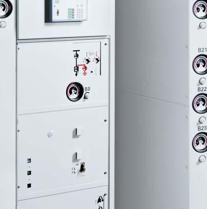
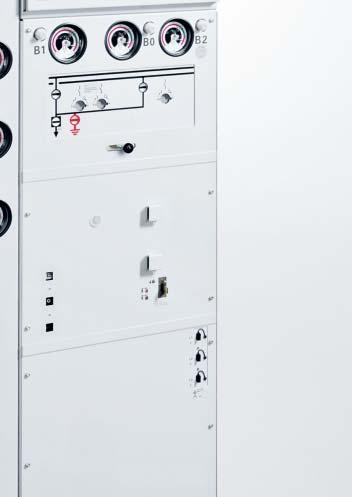
36 Design Basic panel design Insulating system Switchgear housing filled with SF6 gas Features of SF6 gas: Non-toxic Odorless and colorless Non-inflammable Chemically neutral Heavier than air Electronegative (high-quality insulator) Pressure of the SF6 gas in the switchgear housing dependent on the electrical ratings (relative pressure at 0 C): Rated filling level: 50 kpa to 30 kpa Design pressure: 90 kpa Design temperature of the SF 6 gas: 90 C Operating pressure of bursting disc: 300 kpa Bursting pressure: kpa Gas leakage rate: < 0. % per year. Panel design Factory-assembled, type-tested Single-pole metal-enclosed, metalclad Hermetically bolted switchgear housings made of corrosion-resistant aluminum alloy Switchpanel poles arranged one behind the other Maintenance-free in an indoor environment (IEC 67- and VDE 067-) Degree of protection IP 65 for all high-voltage parts of the primary circuit IP 3XD for the switchgear enclosure Option: IP 3D for the switchgear enclosure Option: IP 5 for the low-voltage compartment Vacuum circuit-breaker Three-position for disconnecting and earthing Make-proof earthing by means of the vacuum circuit-breaker Cable connection with inside-cone plug-in system according to EN 50 8 Wall-standing or free-standing arrangement Instrument transformers removable, as they are located outside the gas compartments Subframe, front cover, rear cover and end walls powder-coated in color light basic (SN 0) Low-voltage compartment removable, plug-in bus wires Standardized production processes and certified quality and environmental management system according to ISO 900 and ISO 00. Panel design (examples) D0 Panel for single-busbar switchgear 8DB0 Panel for double-busbar switchgear H35-68 eps Legend for 8D0 and 8DB0 Low-voltage compartment Electronic control board, e.g. multifunction protection 3 Operating mechanism and interlock for threeposition, as well as mechanical position indicators for three-position and circuit-breaker Manometer for gas monitoring of feeder gas compartments 5 Circuit-breaker operating mechanism 6 Voltage detecting system H eps 36 Fixed-Mounted Circuit-Breaker Switchgear Type 8D and 8DB up to 0.5 kv, Gas-Insulated Siemens H
37 Design Basic panel design Single-pole and double-pole design for C traction power supply Panel design (examples) Typical uses Single-pole and double-pole panels 8D/ for the supply of overhead contact line sections in C traction power supply systems Double-pole panels 8D for application in traction power supply systems with autotransformers, e.g. for highspeed railway traffic. Panel design Panel design based on standard version of single-busbar switchgear 8D0. 8D Single-pole switchgear panel for traction power supply. 8D Double-pole switchgear panel for traction power supply H35-68 eps Legend for 8D and 8D Low-voltage compartment Electronic control board, e.g. multifunction protection 3 Operating mechanism and interlock for threeposition, as well as mechanical position indicators for three-position and circuit-breaker Manometer for gas monitoring of feeder gas compartments 5 Circuit-breaker operating mechanism 6 Voltage detecting system 8D Single-pole switchgear panel for traction power supply H eps 8D Double-pole switchgear panel for traction power supply Fixed-Mounted Circuit-Breaker Switchgear Type 8D and 8DB up to 0.5 kv, Gas-Insulated Siemens H
38 Design Gas compartment scheme of 8D0 Gas compartment scheme Sealed pressure system (according to IEC 67-) No refilling required throughout the entire service life Gas compartments distributed to several areas Gas pressure manometers arranged at the switchgear front Gas pressure can be read with security even without auxiliary voltage supply SF6 gas filling equipment with nonreturn valve arranged at the switchgear front beside the associated gas pressure manometer Gas pressure manometers with two signaling contacts for gas pressure too low / gas pressure too high indication Option: Gas pressure manometers with three signaling contacts for gas pressure too low / very low and gas pressure too high indication Option: Gas pressure manometers with temperature and pressure compensation. H35-78 eps rrangement of gas compartments in 8D0 3 Single-busbar panel 8D0 Bushing pervious to gas Gas-tight bushing 5,, 3,, 3,, 3 H35- eps Single-busbar switchgear 8D0 Legend for 8D0 Busbar L (manometer B) Busbar L (manometer B) 3 Busbar L3 (manometer B3) Circuit-breaker L, L, L3 (manometer B0) 5 Top-mounted bus sectionalizer L, L, L3 (manometer B6) 38 Fixed-Mounted Circuit-Breaker Switchgear Type 8D and 8DB up to 0.5 kv, Gas-Insulated Siemens H
39 Design Gas compartment scheme of 8DB0 rrangement of gas compartments in 8DB H35-79 eps Double-busbar panel 8DB0 Bushing pervious to gas Gas-tight bushing 0,, 3, 5, 6,, 3, 5, 6,, 3, 5, H35-7a eps Double-busbar switchgear 8DB0 Legend for 8DB0 Busbar system, L (manometer B) Busbar system, L (manometer B) 3 Busbar system, L3 (manometer B3) Busbar system, L (manometer B) 5 Busbar system, L (manometer B) 6 Busbar system, L3 (manometer B3) 7 Three-position, busbar system, L, L, L3 (manometer B) 8 Disconnector, busbar system, L, L, L3 (manometer B) 9 Circuit-breaker L, L, L3 (manometer B0) 0 Top-mounted bus sectionalizer, busbar system, L, L, L3 (manometer B6) Top-mounted bus sectionalizer, busbar system, L, L, L3 (manometer B6) Fixed-Mounted Circuit-Breaker Switchgear Type 8D and 8DB up to 0.5 kv, Gas-Insulated Siemens H

40 Components Vacuum circuit-breaker Features ccording to IEC and VDE (for standards, see page 60) pplication in hermetically bolted switchgear housings in conformity with the system Vacuum interrupter in SF 6 -filled switchgear housing Maintenance-free for indoor installation according to IEC 67- and VDE 067- Individual secondary equipment metal bellows is used for gasketless separation of the SF 6 insulation and the operating mechanism (already used with success for over million vacuum interrupters). R-H35-38.eps Trip-free mechanism The vacuum circuit-breaker is fitted with a trip-free mechanism according to IEC and VDE Switching duties and operating mechanisms The switching duties of the vacuum circuit-breaker are dependent, among other factors, on its type of operating mechanism. Motor operating mechanism Motor-operating stored-energy mechanism For auto-reclosing (K) For synchronization and rapid load transfer (U) Further operating mechanism features Located outside the switchgear housings in the operating mechanism box and behind the control board Stored-energy spring mechanism for 0,000 operating cycles optional: Stored-energy spring mechanism for 30,000 operating cycles. Operating mechanism functions Motor operating mechanism ) (M *) In the case of motor operating mechanism, the closing spring is charged by means of a motor and latched in the charged position ( spring charged indication is visible). Closing is effected either by means of an ON pushbutton or a closing solenoid. The closing spring is recharged automatically (for auto-reclosing) Circuit-breaker operating mechanism 3H9 for 8D and 8DB Endurance class of circuit-breaker Function Class Standard Property of 8D and 8DB BREKING M IEC ,000 times mechanically without maintenance E IEC ,000 times rated normal current without maintenance 50 times short-circuit breaking current without maintenance C IEC Very low probability of restrikes Operating times Closing time Closing solenoid < 95 ms Opening time st shunt release nd shunt release Undervoltage release < 65 ms < 55 ms < 55 ms rcing time at 50 Hz at 60 Hz Break time at 50 Hz st shunt release nd shunt release Undervoltage release Dead time Total charging time < 5 ms < ms < ms < ms < ms 300 ms < 5 s ON pushbutton uxiliary switch S 3 Closing coil for CLOSE Tripping coil for OPEN 5 OFF pushbutton 6 Operating shaft for circuit-breaker 7 Opening spring 8 Operations counter 9 Position indicator for circuit-breaker 0 Closing spring charged / not charged indicator uxiliary switch Closing spring 3 Gear with hand crank coupling Rating plate bbreviations for switching duties: U = Synchronization and rapid load transfer K = uto-reclosing ) Motor rating at V to 0 V DC: 500 W 0 V and 0 V C: 650 V * Item designation For further technical data and description of typical applications, please refer also to Catalog HG.0 3H Vacuum Circuit-Breakers 0 Fixed-Mounted Circuit-Breaker Switchgear Type 8D and 8DB up to 0.5 kv, Gas-Insulated Siemens H
41 Components Vacuum circuit-breaker Secondary equipment The scope of the secondary equipment of the vacuum circuitbreaker depends on the type of application and offers a wide range of possible variations, allowing almost every requirement to be satisfied: Closing solenoid Type 3Y5 0 (Y9 *) For electrical closing. Shunt releases Types: Standard: 3Y5 0 (Y *) Option: 3X 0 (Y *), with energy store Tripping by protection relay or electrical actuation. Undervoltage release Type 3X 03 (Y7 *) Comprising: Energy store and unlatching mechanism Electromagnetic system, which is permanently connected to voltage while the vacuum circuit-breaker is closed; tripping is initiated when this voltage drops Connection to voltage transformers possible. nti-pumping Function: If constant CLOSE and OPEN commands are present at the vacuum circuit-breaker at the same time, the vacuum circuit-breaker will return to the open position after closing. It remains in this position until a new CLOSE command is given. In this manner, continuous closing and opening (= pumping) is avoided. Circuit-breaker tripping signal For electrical signaling (as pulse > 0 ms), e.g. to remote control systems, in the case of automatic tripping (e.g. protection) Via limit switch (S6 *) and cutout switch (S7 *). Varistor module To limit overvoltages to approx. 500 V for protection devices (when inductive components are mounted in the vacuum circuit-breaker) For auxiliary voltages 60 V DC. uxiliary switch Type 3SV9 (S *) Standard: 6 NO + 6 NC Option: NO + NC. Position switch Type 3SE (S *) For signaling closing spring charged. Mechanical interlock Mechanical interlocking to the three-position During operation of the three-position, the vacuum circuit-breaker cannot be closed. Operating cycle diagram Permissible operating cycles k Breaking current (r.m.s. value) Examples Electrical data (curve ) Rated short-circuit breaking current 5 k Rated normal current 50 Electrical data (curve ) Rated short-circuit breaking current 3.5 k Rated normal current 000 Electrical data (curve 3) Rated short-circuit breaking current 0 k Rated normal current 500 Rated operating sequences Rapid load transfer (U): O-t-CO-t -CO (t = 0.3 s, t = 3 min) uto-reclosing (K): O-t-CO-t -CO (t = 0.3 s, t = 3 min) O = OPEN operation CO = CLOSE operation with subsequent OPEN operation at the shortest internal close-open time of the vacuum circuit-breaker Possible release combinations Release 3 st shunt release type type 3Y5 0 nd shunt release type type 3Y 0 Undervoltage release type 3X 03 3 H35-678_en eps bbreviations: NO = normally open contact NC = normally closed contact * Item designation Fixed-Mounted Circuit-Breaker Switchgear Type 8D and 8DB up to 0.5 kv, Gas-Insulated Siemens H
42 Components Three-position Features Rated normal currents up to 500 Up to 000 operating cycles for the Option: Up to 3000 operating cycles for the Up to 000 operating cycles for the earthing switch Option: Up to 000 operating cycles for the earthing switch Operating shaft and contact blades with common center of rotation and reliable switch position up to the operating front of the panel Gas-tight bushings separate the busbar and circuit-breaker housings under the busbar contacts Cable connection and circuit-breaker housings can be removed without interrupting busbar operation Maintenance-free. Switch positions CLOSED, OPEN, ERTHED or REDY-TO-ERTH CLOSED: Contact blades connected with the busbar: Main circuit closed between busbar and circuit-breaker OPEN: Main circuit open between busbar and circuit-breaker: Test voltages for isolating distances are withstood REDY-TO-ERTH: Contact blades connected with the earthing contact ERTHED: Feeder earthed and short-circuited by closing the circuit-breaker. Operating mechanism Only permissible operations possible due to logical mechanical interlocks Mechanically coupled position indicator Separate operating shafts for the disconnecting, earthing and ready-to-earth functions With manual operating mechanism Option: With motor operating mechanism Motor rating at V to 59 V DC: W 0 V to 0 V C: V Same sense of rotation for the switching operations of the CLOSE or OPEN functions. Position indicators of 8D0 for three-position and vacuum circuit-breaker H35-73a eps H35-7a eps H35-76a eps Feeder OPEN Feeder CLOSED -Q -Q0 -Q -Q -Q0 -Q0 Feeder REDY-TO-ERTH Endurance class of three-position Function Class Standard Property of 8D and 8DB DISCONNECTING M IEC times mechanically without maintenance REDY-TO-ERTH 000 times mechanically without maintenance ERTHING E ) IEC times rated shortcircuit making current I ma without maintenance H35-75a eps -Q -Q0 Endurance class of make-proof earthing switch Function Class Standard Property of 8D and 8DB ERTHING E IEC times mechanically without maintenance times rated shortcircuit making current I ma without maintenance max. I ma = 3.5 k Feeder ERTHED ) By closing the circuit-breaker Fixed-Mounted Circuit-Breaker Switchgear Type 8D and 8DB up to 0.5 kv, Gas-Insulated Siemens H
43 Components Three-position Interlocks Selection of permissible switching operations by means of a selector key with mechanically interlocked vacuum circuitbreaker Selection of permissible switching operations in double-busbar switchgear additionally by means of a control gate with mechanically interlocked vacuum circuit-breaker Corresponding operating shafts are not released at the operating front until they have been pre-selected with the selector key or the control gate Operating lever cannot be removed until switching operation has been completed Circuit-breaker cannot be closed until selector key and control gate is in neutral position again Option: Switchgear interlocking system with electromechanical interlocks (mechanical interlocking for manual operation remains). Position indicators of 8DB0 for three-position and vacuum circuit-breaker H35-77a eps Feeder OPEN -Q -Q0 -Q -Q -Q H35-78a eps -Q0 Feeder busbar system CLOSED -Q -Q H35-79a eps -Q0 Feeder busbar system CLOSED -Q -Q H35-730a eps -Q0 Feeder REDY-TO-ERTH -Q -Q H35-73a eps -Q0 Feeder ERTHED Fixed-Mounted Circuit-Breaker Switchgear Type 8D and 8DB up to 0.5 kv, Gas-Insulated Siemens H

 and earthing function () in accordance with the circuit-breaker position ctuating openings ( and 3) cannot be opened with a selector key as long as")
44 Components Control board Features Mechanical control board below the low-voltage compartment ctuations directly at the operating mechanisms Mechanical position indicators integrated in the mimic diagram Unambiguous assignment of actuating openings and control elements to the corresponding position indicators Ergonomic height of all control elements. Interlocking Panel-internal mechanical interlocks Operation of three-position (CLOSED, OPEN, ERTHED or REDY-TO-ERTH) Vacuum circuit-breaker interlocked mechanically Selector lock () opens or locks the actuating openings for the disconnecting (3) and earthing function () in accordance with the circuit-breaker position ctuating openings ( and 3) cannot be opened with a selector key as long as the vacuum circuit-breaker is in CLOSED position Operating lever can be inserted when the actuating openings are open Operating lever cannot be removed before the definite end position of the disconnecting or earthing function is reached nor can the selector key, and it must be in neutral position Feeder de-earthing is secured by the vacuum circuit-breaker electrically via the auxiliary switch mechanically through the lever (3) of the mechanical circuit-breaker tripping block. Single-busbar panels 8D0 5 6 Double-busbar panels 8DB0 B B R-H35-39.eps R-H35-0.eps Operating mechanism of the three-position CLOSED/OPEN position indicator for disconnecting function of three-position ctuating opening for earthing function 3 ctuating opening for function ctuating opening for selector lock of respective switching operation 5 CLOSED/OPEN position indicator for earthing function of three-position 6 CLOSED/OPEN position indicator for vacuum circuit-breaker 7 CLOSED/OPEN position indicator for nd in double-busbar systems 8 ctuating opening for nd in double-busbar systems 9 Control gate for selecting the three-position or the in doublebusbar systems B Operating mechanism of the vacuum circuit-breaker 0 Mechanical ON pushbutton for vacuum circuit-breaker ctuating opening for manual charging of the circuit-breaker operating spring Mechanical OFF pushbutton for vacuum circuit-breaker 3 Lever for locking the vacuum circuit-breaker against de-earthing Circuit-breaker spring charged indicator 5 CLOSED/OPEN position indicator for vacuum circuit-breaker 6 Operating cycle counter for vacuum circuit-breaker Fixed-Mounted Circuit-Breaker Switchgear Type 8D and 8DB up to 0.5 kv, Gas-Insulated Siemens H
45 Components Busbar, busbar components Busbar features Single-pole enclosure with modular switchgear housings made of corrosion-resistant aluminum alloy Continuous SF6 insulation without plug-in connections or adapters No alteration of the insulating medium throughout the complete busbar assembly Up to 000 with copper bar connection in one busbar housing 5000 with copper bar connection in two busbar housings (twin busbar). H eps Busbar versions Busbar version up to 000 Example 8D0 H eps Busbar version 5000 (twin busbar) Example 8D0 Design of busbar components The busbars of single-busbar switchgear 8D and doublebusbar switchgear 8DB can be equipped with the following busbar components: Plug-in, metal-enclosed busbar voltage transformers with or without three-position Busbar current transformers Busbar connection with cable plug, or with solid-insulated or gas-insulated bar connection, with or without three-position Busbar earthing switch or make-proof earthing switch Capacitive voltage detecting system according to IEC 63-5 or IEC 6958 Top-mounted bus sectionalizer for distribution into two busbar sections without additional switchgear panels and space. H eps Busbar version 5000 (twin busbar) Example 8DB0 Busbar components Busbar connection with cable plug size S or size S3 Busbar connection with solidinsulated or gas-insulated bar H eps H eps H eps Top-mounted bus sectionalizer Fixed-Mounted Circuit-Breaker Switchgear Type 8D and 8DB up to 0.5 kv, Gas-Insulated Siemens H
46 Components Current transformers Features ccording to IEC - and VDE 0- Designed as ring-core current transformers, single-pole Free of dielectrically stressed cast-resin parts (due to design) Insulation class E Inductive type Certifiable Climate-independent Secondary connection by means of a terminal strip in the low-voltage compartment of the panel Cast-resin insulated. Current transformers E B Installation rranged outside the primary enclosure (switchgear housing). C C Mounting locations On the busbar On the circuit-breaker housing On the panel connection housing On the cable. H35-69 eps Current transformer installation (basic scheme) H eps D B Feeder current transformer on the circuit-breaker housing C Feeder current transformer on the panel connection housing D Feeder current transformer on the cable E Busbar current transformer Electrical data * Designation Operating voltage Rated short-duration powerfrequency withstand voltage (winding test) Rated frequency Rated continuous thermal current Rated thermal short-time current, max. 3 s Rated current dynamic primary secondary Type MC max. 0.8 kv 3 kv 50 / 60 Hz max.. rated current (primary) max. 0 k unlimited 0 to 500 and 5 Designation Multiratio (secondary) Core data according to rated primary current: Measuring core Rating Class Overcurrent factor Protection core Rating Class Overcurrent factor Permissible ambient air temperature Insulation class Type MC to max. 3 cores.5 V to 30 V 0. to FS 5, FS 0.5 V to 30 V 5 P or 0 P 0 to 30 max. 60 C E * Further electrical data on request 6 Fixed-Mounted Circuit-Breaker Switchgear Type 8D and 8DB up to 0.5 kv, Gas-Insulated Siemens H
47 Components Voltage transformers Features ccording to IEC - and VDE 0- Single-pole, plug-in design Connection system with plug-in contact according to EN 508 Inductive type Safe-to-touch due to metal enclosure Certifiable Climate-independent Secondary connection by means of plugs in the low-voltage compartment of the panel Cast-resin insulated. Installation rranged outside the primary enclosure (switchgear housing). Voltage transformers 3 Mounting locations On the busbar t the panel connection housing. Voltage transformer types Busbar voltage transformers MT3 and MU Pluggable on the busbar with plug-in system according to EN 508 No separate metering panel required O ption: Three-position for busbar voltage transformer CLOSED - OPEN - ERTHED O ption MU: Repeat test at % of the rated short-duration power-frequency withstand voltage possible with mounted voltage transformer. Feeder voltage transformers MT7 and MU3 Pluggable at the feeder with plug-in system according to EN 508 Connection of MT7 directly at the panel connection housing Connection of MU3 via flexible cable with plug size S at the panel connection housing, and metal-enclosed voltage transformer. H35-73a eps Voltage transformer installation (basic scheme) Busbar voltage transformer MT3 Feeder voltage transformer MT7 (connection at panel connection housing) 3 Busbar voltage transformer MU with threeposition Feeder voltage transformer MU3 (not in the panel, connection via flexible cable with plug size S at the panel connection housing, and metal-enclosed voltage transformer) Electrical data (maximum values) Designation MT3 MU MT7 MU3 Rated voltage kv Rated short-duration power-frequency withstand voltage kv Rated lightning impulse withstand voltage kv Rated voltage factor U n /8h =.9 U n /8h =.9 U n /8h =.9 U n /8h =.9 U n /continuous =. U n /continuous =. U n /continuous =. Standard IEC IEC IEC IEC GOST GOST GOST GOST GB GB GB GB H eps U n /continuous =. Fixed-Mounted Circuit-Breaker Switchgear Type 8D and 8DB up to 0.5 kv, Gas-Insulated Siemens H
48 Components Panel connection Features Bushings for plugs with insidecone plug-in system according to EN 508 Single and multiple connections possible per phase Connection of several cables with different plug sizes possible per phase Connection of solid-insulated or gas-insulated bar possible Connection of MT7 voltage transformer plugged in at the panel connection housing version 9 Connection of MU3 voltage transformer via flexible cable and plug size at the panel connection housing For rated normal currents up to 500. Surge arresters Pluggable via inside-cone plug-in system size or 3 Surge arresters recommended if, at the same time, the cable system is directly connected to the overhead line, the protection zone of the surge arrester at the end tower of the overhead line does not cover the switchgear. Panel connection of 8D0, 8D/ for cable plugs and bar systems 07 H eps 7 H eps 66 H eps Panel connection version Panel connection version Panel connection version 3 37 H eps 35 H35-0 eps 38 H35- eps Panel connection version Panel connection version 5 Panel connection version H35- eps 58 H35-3 eps H35- eps Panel connection version 7 Panel connection version 8 Panel connection version 9 56 H35-5 eps 577 H35-6 eps Panel connection housing Standard subframe 3 Voltage transformer MT7 Panel connection version 0 Panel connection version 8 Fixed-Mounted Circuit-Breaker Switchgear Type 8D and 8DB up to 0.5 kv, Gas-Insulated Siemens H
49 Components Panel connection 07 Panel connection of 8DB0 for cable plugs and bar systems H35-7 eps Panel connection version 7 H35-8 eps Panel connection version 66 H35-9 eps Panel connection version 3 Panel connection version 3 Size S S3 S S S3 Quantity Panel connection version 5 6 Size S S S3 Quantity H35- eps Panel connection version H35-73 eps Panel connection version 7 H35-76 eps Panel connection version H35-7 eps Panel connection version 5 H35-7 eps Panel connection version 8 H35-77 eps Panel connection version H35-7 eps Panel connection version 6 H35-75 eps Panel connection version 9 Panel connection housing Standard subframe 3 Voltage transformer MT7 3 Panel connection version 7 8 Size S S3 S S S3 Solidinsulated bar Quantity Panel connection version 9 Size MT7 S S3 Solidinsulated bar Quantity Panel connection version 0 Solid-insulated bar connection Panel connection version Gas-insulated bar connection Fixed-Mounted Circuit-Breaker Switchgear Type 8D and 8DB up to 0.5 kv, Gas-Insulated Siemens H
50 Components Panel connection (commercially available cable plugs and bar connections) Busbar and panel connection (commercially available cable plugs) Cable type Cable sealing end Remark Make Type Size Diameter across cable insulation mm Thermoplastic-insulated cables kv according to IEC and VDE Single-core cable or three-core cable, PE and XLPE-insulated, NYSY (Cu) and NXSY (Cu) or NYSY (l) and NXSY (l) Conductor cross-section mm nkt cables CPI Insulation material silicone rubber, with or without metal housing, installation without CPI special tools Pfisterer CONNEX Insulation material silicone rubber, with CONNEX metal housing CONNEX Südkabel SEIK Insulation material silicone rubber, with SEIK metal housing Thermoplastic-insulated cables kv according to IEC and VDE Single-core cable or three-core cable, PE and XLPE-insulated, NYSY (Cu) and NXSY (Cu) or NYSY (l) and NXSY (l) nkt cables CPI Insulation material silicone rubber, with or without metal housing, installation without CPI special tools Pfisterer CONNEX Insulation material silicone rubber, with CONNEX metal housing CONNEX Südkabel SEIK Insulation material silicone rubber, with SEIK metal housing Thermoplastic-insulated cables 36 kv according to IEC and VDE Single-core cable or three-core cable, PE and XLPE-insulated, NYSY (Cu) and NXSY (Cu) or NYSY (l) and NXSY (l) nkt cables CPI Insulation material silicone rubber, with or without metal housing, installation without CPI special tools Pfisterer CONNEX Insulation material silicone rubber, with CONNEX metal housing CONNEX Südkabel SEIK Insulation material silicone rubber, with SEIK metal housing Busbar and panel connection (commercially available bar systems) Bar type Bar connection Remark Make Type Conductor material Max. rated current Solid-insulated bar MGC Duresca DE luminum 500 Outer sheath made of polyamide Moser Glaser Duresca DE Copper 500 (polyamide tube) Duresca DG luminum 500 Outer sheath made of CrNi steel or Duresca DG Copper 500 aluminum (metal sheath) Preissinger ISOBUS MR ISOBUS MR luminum Copper Outer sheath made of heat shrinkable tube; insulated with cast-resin impregnated paper bandage Ritz SIS luminum 500 Outer sheath made of heat shrinkable tube (up to kv) SIS Copper 500 Gas-insulated bar MGC Gaslink Copper 500 luminum housing Moser Glaser Preissinger ISOBUS MG Copper 500 luminum housing Busbar and panel connection (commercially available dummy plugs) ccessories Dummy plug Remark Make Type Size Rated voltage Inside-cone plug-in system according to EN 508 nkt cables FPI 0.5 kv Insulation material silicone rubber, with FPI kv metal cover Pfisterer Blindstecker 0.5 kv Insulation material silicone rubber, with kv metal cover 0.5 kv Südkabel ISIK //3 / / 0.5 kv Insulation material silicone rubber, with ISIK 5/5/35 3 / / 0.5 kv metal cover 50 Fixed-Mounted Circuit-Breaker Switchgear Type 8D and 8DB up to 0.5 kv, Gas-Insulated Siemens H


51 Components Indicating and measuring equipment Voltage detecting systems according to IEC 63-5 or VDE To verify safe isolation from supply LRM detecting systems with plug-in indicator with integrated indicator, type VOIS+, VOIS R+, WEG, ZERO with integrated indicator, with integrated repeat test of the interface, with integrated function test, type CPDIS-S+, WEG., and additionally with integrated signaling relays type CPDIS-S+, WEG.. R-H0-03 eps Indicators and detecting systems Plug-in voltage indicator per phase at the panel front Symbols shown 0 3 VOIS+, VOIS R+ CPDIS-S+ CPDIS-S+ L L L3 L L L3 L L L3 Plug-in voltage indicator Verification of safe isolation from supply phase by phase Indicator suitable for continuous operation Measuring system and voltage indicator can be tested Voltage indicator flashes if high voltage is present. VOIS+, VOIS R+ Integrated display, without auxiliary power With indication "" to "3" (see legend) Maintenance-free, repeat test required With integrated 3-phase LRM test socket for phase comparison With integrated signaling relays (only VOIS R+). CPDIS-Sx+ Common features Maintenance-free Integrated display, without auxiliary power Integrated repeat test of the interfaces (self-monitoring) With integrated function test (without auxiliary power) by pressing the Display- Test pushbutton With integrated 3-phase LRM test socket for phase comparison. CPDIS-S+ Without auxiliary power With indication to 5 (see legend) Without ready-for-service monitoring Without signaling relays (thus without auxiliary contacts). CPDIS-S+ With indication "0" to "6" (see legend) Only by pressing the Display-Test pushbutton: ERROR indication (6), e.g. in case of missing auxiliary voltage With ready-for-service monitoring (external auxiliary power required) With integrated signaling relay for signals (auxiliary power required). R-H0-0 eps R-H0-0a eps Integrated voltage indicator VOIS+, VOIS R+ Integrated voltage detecting system CPDIS-S+, -S+ H35-537a eps C U LE C U LRM system plugged in Voltage indication via capacitive voltage divider (principle) 5 6 ERROR 0 CPDIS-S+: Operating voltage not present Operating voltage present Operating voltage not present, For CPDIS-S+: uxiliary power not present 3 Failure in phase L, operating voltage at L and L3 (for CPDIS-Sx+ also earth-fault indication) Voltage (not operating voltage) present 5 Indication Display-Test passed 6 Indication ERROR, e.g.: in case of missing auxiliary voltage L L L3 CPDIS/VOIS installed C Capacity integrated into bushing C Capacity of the connection leads and the voltage indicator to earth U LE = U N / 3 during rated operation in the three-phase system U = U = Voltage at the capacitive interface of the switchgear or at the voltage indicator H35-579a eps Fixed-Mounted Circuit-Breaker Switchgear Type 8D and 8DB up to 0.5 kv, Gas-Insulated Siemens H

 by pressing the \"Display-Test\" pushbutton With integrated 3-phase LRM test socket for phase comparison Without integrated signaling relay Without auxiliary power. WEG.")
52 Components Indicating and measuring equipment WEG ZERO Voltage detecting system according to IEC 6958 or VDE With indication to 3 (see legend) Maintenance-free, repeat test required With integrated 3-phase test socket for phase comparison. WEG. Voltage detecting system according to IEC 63-5 or VDE With indication to 5 (see legend) Maintenance-free Integrated repeat test of the interface (self-monitoring) With integrated function test (without auxiliary power) by pressing the "Display-Test" pushbutton With integrated 3-phase LRM test socket for phase comparison Without integrated signaling relay Without auxiliary power. WEG. Voltage detecting system according to IEC 63-5 or VDE With indication 0 to 6 (see legend) Maintenance-free Integrated repeat test of the interface (self-monitoring) With integrated function test (without auxiliary power) by pressing the Display-Test pushbutton With integrated 3-phase LRM test socket for phase comparison With integrated signaling relay uxiliary power required. Integrated voltage indicator WEG ZERO Integrated voltage detecting system WEG. Integrated voltage detecting system WEG. H35-537a eps C U LE C U LRM system plugged in Voltage indication via capacitive voltage divider (principle) L L L3 WEG installed C Capacity integrated into bushing C Capacity of the connection leads and the voltage indicator to earth U LE = U N / 3 during rated operation in the three-phase system U = U = Voltage at the capacitive interface of the switchgear or at the voltage indicator R-H35-.eps R-H35-.eps R-H35-3.eps Symbols shown WEG ZERO WEG. WEG. LC display gray: not illuminated LC display white: illuminated 0 For WEG.: Operating voltage not present, auxiliary power present, LCD illuminated Operating voltage present For WEG.: uxiliary power present, LCD illuminated Operating voltage not present For WEG.: uxiliary power not present, LCD not illuminated 3 Failure in phase L, operating voltage at L and L3 For WEG.: uxiliary power present, LCD illuminated Voltage present, current monitoring of coupling section below limit value For WEG.: uxiliary power present, LCD illuminated 5 Indication Display-Test passed For WEG.: uxiliary power present, LCD illuminated 6 For WEG.: LCD for missing auxiliary voltage is not illuminated R-H35-.eps 5 Fixed-Mounted Circuit-Breaker Switchgear Type 8D and 8DB up to 0.5 kv, Gas-Insulated Siemens H
 Safe-to-touch handling of the phase comparison test unit by inserting it into the capacitive taps (socket pairs) of the")

 for: Voltage detection Repeat test Phase comparison Phase sequence test Self-test The")
53 Components Indicating and measuring equipment Verification of correct terminal-phase connections Verification of correct terminalphase connections possible by means of a phase comparison test unit (can be ordered separately) Safe-to-touch handling of the phase comparison test unit by inserting it into the capacitive taps (socket pairs) of the switchgear. Phase comparison test units according to IEC 63-5 or VDE R-H0-059 eps R-H0-089 eps Phase comparison test unit make Pfisterer, type EPV R-H35-7.eps Phase comparison test unit make Horstmann, type ORION 3.0 as combined test unit for: Phase comparison Interface testing at the switchgear Voltage detection for LRM systems Integrated self-test Indication via LED and acoustic alarm Phase comparison test unit make Kries, type CP-Phase as combined test unit (HR and LRM) for: Voltage detection Repeat test Phase comparison Phase sequence test Self-test The unit does not require a battery. Fixed-Mounted Circuit-Breaker Switchgear Type 8D and 8DB up to 0.5 kv, Gas-Insulated Siemens H


 possible.")
 for busbar housings (arranged at the lateral switchgear termination) 3 R-H35-6.eps R-H35-8.")
54 Components Indicating and measuring equipment Ready-for-service indication Components Gas pressure manometers with two or three signaling contacts for gas pressure too low / very low and gas pressure too high indication Simple, visual check of the ready-for-service indicator by red/green indication areas Indication of gas pressure also guaranteed without auxiliary voltage supply SF6 gas filling equipment with non-return valve and bolted protective cap arranged at the switchgear front beside gas pressure manometer Option: Gas pressure manometers with temperature and pressure compensation. Low-voltage compartment For accommodation of protection, control, measuring and metering equipment Partitioned safe-to-touch from the high-voltage part of the panel Low-voltage compartment can be removed, bus wires and control cables are plugged in Option: Higher low-voltage compartment (00 mm instead of mm) possible. Gas monitoring of single-busbar switchgear 8D0/8D/8D Gas pressure manometer () for circuit-breaker housing (arranged at the panel front) Gas monitoring for double-busbar switchgear 8DB0 R-H35-5.eps R-H35-7.eps Gas pressure manometers () for busbar housings (arranged at the lateral switchgear termination) 3 R-H35-6.eps R-H35-8.eps Gas pressure manometers (3) for circuit-breaker and housings (arranged at the panel front) Gas pressure manometers () for busbar housings (arranged at the lateral switchgear termination) 5 Fixed-Mounted Circuit-Breaker Switchgear Type 8D and 8DB up to 0.5 kv, Gas-Insulated Siemens H

 and keyboard for local operation, configuration and indication Four freely programmable LEDs for displaying any desired data Operation")

55 Components Protection, control, measuring and monitoring equipment The low-voltage compartment can accommodate all customary protection, control, measuring and monitoring equipment available on the market (e.g.): Multifunction protection relay SIPROTEC 7SJ / 7SJ60 User-friendly operating program DIGSI for parameterizing and analysis Communications and bus capability Functions: Protection, control, signaling, communication and measuring LC text display ( lines) and keyboard for local operation, configuration and indication Four freely programmable LEDs for displaying any desired data Operation and fault indication memory Fault recording Circuit-breaker control. Multifunction protection relay SIPROTEC 7SJ6 / 7SJ6 For stand-alone or master operation Communications and bus capability Functions: Protection, control, signaling, communication and measuring LC text display ( lines) for process and equipment data, as text, e.g. for Measuring and metering values Information on status of switchgear and switching device Protection data General indications larms Four freely programmable function keys for frequently performed functions Seven freely programmable LEDs for displaying any desired data Keys for navigation in menus and for entering values Fault recording. 7 7 R-H35-0 eps Multifunction protection relays SIPROTEC Multifunction protection relay SIPROTEC 7SJ / 7SJ60 LC display LEDs 3 Key-operated switches Navigation keys 5 Control keys 6 Function keys 7 LC text display Multifunction protection relay SIPROTEC 7SJ63 For stand-alone or master operation Communications and bus capability Functions: Protection, control, signaling, communication and measuring LC display for process and equipment data in the form of a feeder mimic diagram and as text, e.g. for Measuring and metering values Information on status of switchgear and switching device Protection data General indications larms Four freely programmable function keys for frequently performed functions Fourteen freely programmable LEDs for displaying any desired data Two key-operated switches to switch between local and remote control and interlocked and non-interlocked operation Keys for navigation in menus and for entering values Integrated motor control by special relays with enhanced performance Fault recording. 3 R-H35-03 eps Multifunction protection relay SIPROTEC 7SJ6 / 7SJ6 6 5 R-H35-0 eps 6 Multifunction protection relay SIPROTEC 7SJ63 Fixed-Mounted Circuit-Breaker Switchgear Type 8D and 8DB up to 0.5 kv, Gas-Insulated Siemens H
 Cable connection with inside-cone plugin system according to EN 508")
56 Components NSI design Panel design Factory-assembled, type-tested according to IEC 67 Single-pole metal-enclosed, metal-clad Hermetically bolted switchgear housings made of corrosion-resistant aluminum alloy Switchpanel poles arranged one behind the other Maintenance-free in an indoor environment (IEC 67- and VDE 067-) Cable connection with inside-cone plugin system according to EN 508 Wall-standing or free-standing arrangement Subframe, front cover, rear cover and end walls powder-coated in color light basic (SN 0) Low-voltage compartment removable, plug-in bus wires Degree of protection IP 65 for all high-voltage parts of the primary circuit IP 3XD for the switchgear enclosure Option: IP 3D for the switchgear enclosure O ption: IP 5 for the low-voltage compartment Vacuum circuit-breaker Three-position for disconnecting and earthing by means of the circuit-breaker Make-proof earthing by means of the vacuum circuit-breaker Option: Three-position for disconnecting and earthing at the feeder O ption: Disconnector and make-proof earthing switch for disconnecting and make-proof earthing at the feeder For further dimensions and product range, see pages to 35. Insulating system Switchgear housing filled with SF6 gas Features of SF6 gas: Non-toxic Odorless and colorless Non-inflammable Chemically neutral Heavier than air Electronegative (high-quality insulator) Pressure of the SF6 gas in the switchgear housing dependent on the electrical ratings (relative pressure at 0 C): Rated filling level: 50 kpa to 30 kpa Gas leakage rate: < 0. % per year. Basic panel design Example 8D0 Single-busbar panel with three-position at the feeder H35-69 eps H eps Legend for 8D0 Low-voltage compartment Electronic control board, e.g. multifunction protection 3 Operating mechanism and interlock for threeposition, as well as mechanical position indicators for three-position and circuitbreaker Manometer for gas monitoring of feeder gas compartments 5 Circuit-breaker operating mechanism 6 Voltage detecting system 7 Operating mechanism and interlock for the threeposition, as well as mechanical position indicator for the three-position at the feeder 8 Operating mechanism and interlock for the makeproof earthing switch, as well as mechanical position indicator for the make-proof earthing switch at the feeder 9 Operating mechanism and interlock for the, as well as mechanical position indicator for the at the feeder Camera system Camera system for visual monitoring of the switch positions of the s and earthing switches (see also page 58). 9 UL certification For 8D and 8DB NSI design options there is a UL or cul certificate available. Example 8D0 Single-busbar panel with make-proof earthing switch at the feeder 56 Fixed-Mounted Circuit-Breaker Switchgear Type 8D and 8DB up to 0.5 kv, Gas-Insulated Siemens H
57 Components NSI design Electrical data, filling pressure, temperature for single-busbar and double-busbar switchgear according to NSI Common electrical data, filling pressure and temperature Rated insulation level Rated voltage U r kv.76 8, ) Rated short-duration powerfrequency withstand voltage U d : Phase-to-earth, open contact gap kv across the isolating distance kv Rated lightning impulse withstand voltage U p : Phase-to-earth, open contact gap kv across the isolating distance kv Rated frequency f r Hz Rated normal current I 6) r for the busbar ) Rated filling level p re for the busbar 0 kpa (absolute) at 0 C Minimum functional level p me kpa (absolute) at 0 C mbient air temperature 5 C to + 55 C ) Data of the switchgear panels Circuitbreaker panel, panel 3), Rated normal current I 6) r bus sectionalizer Rated short-time withstand current I k t k = 3 s up to k ), bus coupler 5) Rated peak withstand current I p up to k Rated short-circuit making current I ma up to k Rated short-circuit breaking current I sc up to k Electrical endurance of at rated normal current operating cycles vacuum circuit-breakers at rated short-circuit breaking current 50 breaking operations Rated filling level p re for feeders kpa (absolute) at 0 C Minimum functional level p me 30 0 kpa (absolute) at 0 C ) Higher values of the rated voltage available with kv ) Rated normal current of the busbar with UL certification up to 350 3) Disconnector panel available for single-busbar switchgear 8D0 ) Bus sectionalizer not available for rated normal current 5) Bus coupler available for double-busbar switchgear 8DB0 6) Maximum permissible normal current dependent on ambient air temperature Fixed-Mounted Circuit-Breaker Switchgear Type 8D and 8DB up to 0.5 kv, Gas-Insulated Siemens H
 software on a mobile computer.")
58 Components NSI design Camera system 8D and 8DB switchgear can be designed according to NSI requirements. For this purpose, every three-position is equipped with a digital camera monitoring system. The CLOSED - OPEN - ERTHED positions are transmitted per phase through a USB / Firewire interface and signaled to the Siemens Disconnector Tool (SDT) software on a mobile computer. Current transformer features Designed as ring-core current transformers, single-pole Free of dielectrically stressed castresin parts (due to design) Inductive type Climate-independent Secondary connection by means of a terminal strip in the low-voltage compartment of the panel Cast-resin insulated. Voltage transformer features Single-pole, plug-in design Connection system with plug-in contact according to EN 508 Inductive type Safe-to-touch due to metal enclosure Climate-independent Secondary connection by means of plugs in the low-voltage compartment of the panel Cast-resin insulated. Installation rranged outside the primary enclosure (switchgear housing). Internal arc classification Internal arcing test according to IEEE Std C (see also page 3). H35-69 eps Current transformer installation (basic scheme) B Feeder current transformer on the circuit-breaker housing C Feeder current transformer on the panel connection housing D Feeder current transformer on the cable E Busbar current transformer Option: Feeder current transformer between circuit-breaker and three-position on the busbar E B C D H35-73a eps Voltage transformer installation (basic scheme) Busbar voltage transformer GBE with primary fuses and three-position Feeder voltage transformer GBEI with primary fuses (not in the panel, connection via flexible cable with plug size at the panel connection housing and metalenclosed voltage transformer) Firewire interface USB interface R-H35-9.eps USB and Firewire interface for visual monitoring of the positions of the three-position 58 Fixed-Mounted Circuit-Breaker Switchgear Type 8D and 8DB up to 0.5 kv, Gas-Insulated Siemens H
59 Components NSI design Option: In accordance with NSI requirements, 8D and 8DB switchgear can be equipped with an additional threeposition or and make-proof earthing switch at the feeder. Features Rated normal currents up to 000 Up to 000 operating cycles for the Up to 000 operating cycles for the earthing switch Up to 000 operating cycles for the make-proof earthing switch Operating shaft and contacts with common center of rotation and reliable switch position up to the operating front of the panel Gas-tight bushings separate the busbar and circuit-breaker housings under the busbar contacts Cable connection and circuit-breaker housings can be removed without interrupting busbar operation Maintenance-free. Example: Position indicators of 8D0 with additional three-position at the feeder H35-736a eps Feeder OPEN -Q -Q0 5x -Q9 Switch positions CLOSED, OPEN, ERTHED or REDY- TO-ERTH CLOSED: Disconnector contact connected with the busbar: Main circuit closed between busbar, circuit-breaker and feeder OPEN: Main circuit open between busbar, circuit-breaker and feeder: Test voltages for isolating distances are withstood REDY-TO-ERTH: Contact blades connected with the earthing contact ERTHED: Circuit-breaker closed. Three-position at the feeder connected with earthing contact. Operating mechanism Only permissible operations possible due to logical mechanical interlocks Mechanically coupled position indicators Separate operating shafts for the disconnecting, earthing and ready-to-earth functions With manual operating mechanism O ption: With motor operating mechanism Motor rating at V to 59 V DC: W 0 V to 0 V C: V Same sense of rotation for the switching operations of the CLOSE or OPEN functions. H35-737a eps H35-738a eps Feeder CLOSED -Q -Q0 5x -Q9 -Q -Q0 5x -Q9 Feeder ERTHED Fixed-Mounted Circuit-Breaker Switchgear Type 8D and 8DB up to 0.5 kv, Gas-Insulated Siemens H
60 Standards Standards, specifications, guidelines Type of service location The switchgear can be used as indoor installation according to IEC 6936 (Power installations exceeding kv C) and VDE 00 Outside lockable electrical service locations at places which are not accessible to the public. Enclosures of switchgear can only be removed with tools In lockable electrical service locations. lockable electrical service location is a place outdoors or indoors that is reserved exclusively for housing electrical equipment and which is kept under lock and key. ccess is restricted to authorized personnel and persons who have been properly instructed in electrical engineering. Untrained or unskilled persons may only enter under the supervision of authorized personnel or properly instructed persons. Terms Make-proof earthing switches are earthing switches with short-circuit making capacity according to IEC 67-0 and VDE / EN Dielectric strength The dielectric strength is verified by testing the switchgear with rated values of short-duration power-frequency withstand voltage and lightning impulse withstand voltage according to IEC/EN 67- / VDE 067- (see table Dielectric strength ) The rated values are referred to sea level and to normal atmospheric conditions (03 hpa, 0 C, g/m 3 humidity according to IEC 7 and VDE 0). The gas insulation at a relative gas pressure of > 50 kpa permits switchgear installation at any desired altitude above sea level without the dielectric strength being adversely affected. Table Dielectric strength Single-busbar and double-busbar switchgear 8D0 and 8DB0 Rated voltage kv Rated short-duration power-frequency withstand voltage Between phases and to earth kv cross isolating distances kv Rated lightning impulse withstand voltage Between phases and to earth kv cross isolating distances kv Table Dielectric strength Traction power supply switchgear 8D/ Rated voltage according to EN 50- kv Nominal voltage according to 5 5 IEC 60 / EN 5063 kv Rated short-duration power-frequency withstand voltage Between phases and to earth kv cross isolating distances kv 60 0 Rated lighting impulse withstand voltage Between phases and to earth kv 5 00 cross isolating distances kv 5 0 Standards 8D and 8DB switchgear complies with the relevant standards and specifications applicable at the time of type tests. In accordance with the harmonization agreement reached by the countries of the European Union, their national specifications conform to the IEC standard. Overview of standards (December 009) IEC standard VDE standard EN standard Switchgear 8D and 8DB IEC 67- VDE 067- EN 6 7- IEC VDE EN Devices Circuit-breakers IEC VDE EN Disconnectors and earthing switches IEC 67-0 VDE EN Voltage detecting systems IEC 63-5 VDE EN Degree of protection IP code IEC 6059 VDE 0- EN IK code IEC 66 VDE 0-00 EN 50 0 Insulation IEC 7 VDE 0 EN Instrument Current transformers IEC - VDE 0- EN transformers Voltage transformers IEC - VDE 0- EN Installation, erection IEC VDE 00 Insulating gas SF 6 Use and handling of SF 6 IEC VDE EN Specification for new SF 6 IEC VDE EN Guidelines for the checking and treatment of SF 6 taken from electrical equipment IEC 60 VDE EN 60 Overview of standards for traction applications IEC standard EN standard Supply voltage 8D and 8D IEC 60 EN Switchgear 8D and 8D EN 50 5 Insulation 8D and 8D EN Fixed-Mounted Circuit-Breaker Switchgear Type 8D and 8DB up to 0.5 kv, Gas-Insulated Siemens H
61 Standards Standards, specifications, guidelines Current carrying capacity ccording to IEC or IEC 67-, VDE or VDE 067-, the rated normal current refers to the following ambient air temperatures: Maximum of -hour mean + 35 C Maximum + 0 C The current carrying capacity of the panels and busbars depends on the ambient air temperature outside the enclosure. Internal arc classifications Protection of operating personnel by means of tests for verifying the internal arc classification Internal arcing tests must be performed in accordance with IEC or VDE and IEEE Std C Definition of criteria according to IEC or VDE: Criterion Correctly secured doors and covers do not open, limited deformations are accepted Criterion No fragmentation of the enclosure, no projection of small parts above 60 g Criterion 3 No holes in accessible sides up to a height of m Criterion No ignition of indicators due to hot gases Criterion 5 The enclosure remains connected to its earthing point. Resistance to internal faults Due to the single-pole enclosure and the SF 6 insulation of the switchgear and the switching devices, the possibility of faults in SF 6 -insulated switchgear is a mere fraction of that typical of other switchgear types: There are no effects due to external influences, such as: Pollution layers Humidity Small animals and foreign objects Maloperation is practically excluded due to logical arrangement of operating elements Short-circuit-proof feeder earthing by means of the circuit-breaker. In the unlikely event of a fault within the switchgear housing, the energy conversion in the case of an internal arc fault is minor thanks to the SF 6 insulation and the shorter length of the arc, i.e. approximately only /3 compared to air. Resistance to short-circuits and earth faults Two-phase and three-phase short-circuits between the primary conductors are excluded by the single-pole primary enclosure. For installation on even and rigid concrete or steel structure (without considering building influences), the tested ground accelerations meet the following requirements: Uniform Building Code 997 (UBC) Zone California Building Code 998 (CBC) Zone International Building Code 006 (IBC) - 00 % merican Society of Civil Engineers 005 (SCE) - 00 % IEEE High required response spectrum (Figure.). Color of the panel front Siemens standard (SN) G, color light basic (SN0) (similar to RL 7 / gray). Climate and environmental influences 8D and 8DB switchgear is completely enclosed and insensitive to climatic influences. ll medium-voltage devices are installed in gas-tight and bolted switchgear housings made of corrosion-resistant aluminum alloy and filled with SF 6 gas Live parts inside and outside the switchgear housing are provided with single-pole enclosure t no point can creepage currents flow from high-voltage potentials to earth Operating mechanism parts which are functionally important are made of corrosion-resistant materials Bearings in the operating mechanism are designed as drytype bearings and do not require lubrication. Protection against solid foreign objects, electric shock and water 8D and 8DB switchgear fulfills according to the standards IEC 67- VDE 067-, EN 6 7- IEC VDE , EN IEC 6059 VDE 0-, EN IEC 66 VDE 0-00, EN 50 0 the following degrees of protection: Degree of protection Type of protection IP 65 for parts of the primary circuit under high voltage IP 3XD for switchgear enclosure IP 3D for switchgear enclosure (optional) IP 5 for low-voltage compartment (optional) Degree of protection IK 07 Type of protection for switchgear enclosure seismic capacity (optional) 8D and 8DB switchgear can be upgraded for regions at risk from earthquakes. For upgrading, earthquake qualification testing has been carried out in accordance with the following standards: IEC Guidance seismic test methods for equipment IEC Test Ff: Vibration Time-history method IEC Test Fc: Vibration (sinusoidal) IEEE Recommended Practice for Seismic Design of Substations IEEE 3-00 IEEE Recommended Practice for Seismic Qualification of Class E Equipment for Nuclear Power Generating Stations IEEE C IEEE Guide for Seismic Qualification of Class E Metal-Enclosed Power Switchgear ssemblies IEC Recommended practices for seismic qualification of electrical equipment of the safety system for nuclear generating stations Fixed-Mounted Circuit-Breaker Switchgear Type 8D and 8DB up to 0.5 kv, Gas-Insulated Siemens H

 R-H35-50.eps R-H35-5.")

62 First circuit-breaker switchgear 8D0 98 Up to now more than 55,000 8D and 8DB switchgear panels successfully in operation worldwide. (September 009) R-H35-50.eps R-H35-5.eps R-H35-5.eps 6 Fixed-Mounted Circuit-Breaker Switchgear Type 8D and 8DB up to 0.5 kv, Gas-Insulated Siemens H
Fixed-Mounted Circuit-Breaker Switchgear Type 8DA and 8DB up to 40.5 kv, Gas-Insulated
 www.siemens.com/medium-voltage-switchgear Fixed-Mounted Circuit-Breaker Switchgear Type 8D and 8DB up to 0.5 kv, Gas-Insulated Medium-Voltage Switchgear Catalog H 35.11 201 nswers for infrastructure and
Fixed-Mounted Circuit-Breaker Switchgear Type NXPLUS up to 40.5 kv, Gas-Insulated
 www.siemens.com/medium-voltage-switchgear Fixed-Mounted Circuit-Breaker Switchgear Type NXPLUS up to 40.5 kv, Gas-Insulated Medium-Voltage Switchgear Catalog HA 35.5 203 Answers f infrastructure and cities.
Fixed-Mounted Circuit-Breaker Switchgear Type NXPLUS C up to 24 kv, SF 6 -Insulated. Medium-Voltage Switchgear Catalog HA 35.
 Fixed-Mounted Circuit-Breaker Switchgear Type NXPLUS C up to kv, SF 6 -Insulated Medium-Voltage Switchgear Catalog HA 5. 00 Invalid: Catalog HA 5. 00 R-HA5-05 eps Fixed-Mounted Circuit-Breaker Switchgear
Catalog HA Edition up to 24 kv, Air-Insulated, Extendable. Medium-Voltage Switchgear. siemens.com/simosec
 Catalog HA 41.43 Edition 2018 Switchgear Type SIMOSEC, up to 24 kv, Air-Insulated, Extendable Medium-Voltage Switchgear siemens.com/simosec Application Typical uses R-HA41-135.tif R-HA40-112.tif R-HA41-115.tif
NXPLUS C Single busbar. Maintenance-free for lifetime
 NXPLUS C Single busbar Maintenance-free for lifetime Energy Distribution Welcome! Page 2 Content Overview Technical data Typicals Panel design Circuit-Breaker panel Busbar Operation Metering Low-voltage
Switchgear Type SIMOSEC, up to 24 kv, Air-Insulated, Extendable
 www.siemens.com/medium-voltage-switchgear Switchgear Type SIMOSEC, up to 24 kv, Air-Insulated, Extendable Medium-Voltage Switchgear Catalog HA 41.43 2012 Answers for infrastructure and cities. Neue Bilder
Type SIMOPRIME A4, up to 24 kv, Air-Insulated Medium-Voltage Switchgear
 Circuit-Breaker www.siemens.com/energy Switchgear Type SIMOPRIME A4, up to 24 kv, Air-Insulated Medium-Voltage Switchgear s Technology Circuit-Breaker Switchgear Type SIMOPRIME, up to 17.5 kv, Air-Insulated
Switchgear Type 8DJH 36 for Secondary
 Catalog HA 40.3 Edition 2017 Switchgear Type 8DJH 36 for Secondary Distribution Systems up to 36 kv, Gas-Insulated Medium-Voltage Switchgear siemens.com/8djh36 Application Typical uses R-HA40-135.tif R_HA40-150a
Circuit-Breaker Switchgear Type SIMOPRIME, up to 17.5 kv, Air-Insulated Medium-Voltage Switchgear.
 Circuit-Breaker Switchgear Type SIMOPRIME, up to 17.5 kv, Air-Insulated Medium-Voltage Switchgear www.siemens.com/energy Technology s Contents Application Page Benefits 2 Typical uses 2 and 3 Technical
8DJ. Maintenance-free for lifetime
 8DJ Maintenance-free for lifetime Energy Distribution Welcome! Page 2 October 1 st 2008 8DJ Main Applications for Medium-Voltage Switchgear Power generation Power stations G Power transmission High and
Switchgear Type 8BT1, up to 24 kv, air-insulated. Medium Voltage Switchgear Catalog HA 26.
 www.siemens.com/medium-voltage-switchgear Switchgear Type 8BT1, up to 24 kv, air-insulated Medium Voltage Switchgear Catalog HA 26.31 2012 Answers for infrastructure and cities. R-HA26-013. eps Contents
Switchgear Type SIMOSEC, up to 24 kv, Air-Insulated, Extendable
 Switchgear Type SIMOSEC, up to 24 kv, Air-Insulated, Extendable Medium-Voltage Switchgear Totally Integrated Power SIMOSEC Catalog HA 41.43 Edition Sept. 2014 Answers for infrastructure and cities. Neue
Benefits, typical uses
 R-HA26-013. eps Switchgear Type 8BT1, up to 24kV,Air-Insulated Contents Application Page Application Benefits 2 Typical uses 2 and 3 Technical Data Ratings 4 Classification, dimensions, 5 room planning
Switchgear Type 8DJH for Secondary Distribution Systems up to 24 kv, Gas-Insulated
 Catalog HA 40.2 Edition 2017 Switchgear Type 8DJH for Secondary Distribution Systems up to 24 kv, Gas-Insulated Medium-Voltage Switchgear siemens.com/8djh Application Typical uses R-HA40-111.tif R-HA40-112.tif
Switchgear Type 8DJH for Secondary Distribution Systems up to 24 kv, Gas-Insulated
 Switchgear Type 8DJH for Secondary Distribution Systems up to 24 kv, Gas-Insulated Medium-Voltage Switchgear Catalog HA 40.2 2009 Answers for energy. -HA40-111.eps -HA40-110.eps -HA40-109.eps -HA40-112.eps
SION Vacuum Circuit-Breakers. Answers for energy. Medium-Voltage Equipment Selection and Ordering Data. Catalog HG
 Medium-Voltage Equipment Selection and Ordering Data Catalog HG 11.0 008 Answers for energy. R-HG11-17.tif Siemens HG 11.0 008 Contents Contents Page SION Vacuum Circuit-Breakers Description General Construction
SION Vacuum Circuit-Breakers. Answers for energy. Medium-Voltage Equipment Selection and Ordering Data. Catalog HG
 Medium-Voltage Equipment Selection and Ordering Data Catalog HG 11.02 2011 Answers for energy. R-HG11-172.tif 2 Siemens HG 11.02 2011 Contents SION Vacuum Circuit-Breakers Medium-Voltage Equipment Catalog
Switchgear Type 8DJH for Secondary Distribution Systems up to 24 kv, Gas-Insulated
 Switchgear Type 8DJH for Secondary Distribution Systems up to 24 kv, Gas-Insulated Medium-Voltage Switchgear Catalog HA 40.2 2010 Answers for energy. -HA40-110.eps -HA40-109.eps -HA40-112.eps -HA40-111.eps
Types. Fixed-mounted circuitbreaker. NXPLUS C is a factoryassembled,
 R-HA5-05a eps Fixed-Mounted Circuit-Breaker Switchgear Type NXPLUS C, up to kv, Gas-Insulated Contents Application Page Types Application Types, typical uses, ratings to Requirements Features, safety,
CPG.1 Gas insulated, single busbar cubicle range Up to 27 kv / 2000 A / 31.5 ka Up to 38 kv / 2000 A / 31.5 ka IEEE Standards
 Medium Voltage Switchgear Primary Distribution CPG.1 Gas insulated, single busbar cubicle range Up to 27 kv / 2000 A / 31.5 ka General description Presentation Ormazabal s CPG System includes the CPG.1
 medium voltage switchgear manufacturer VACUUM CIRCUIT-BREAKER SWITCHGEAR TYPE SIMOPRIME, UP TO 17.5kV, AIR INSULATED MEDIUM-VOLTAGE SWITCHGEAR. UNDER LICENSE BY SIEMENS. www.simosynergy.com/simoprime VACUUM
Air Insulated Switchgear NXAirS, 40.5kV Answers for infrastructure and cities.
 www.siemens.com.cn/medium-voltage-switchgear Air Insulated Switchgear NXAirS, Answers for infrastructure and cities. Applications Page Application Type 2 Typical uses 3 Classification 3 Type NXAirS withdrawable
Vacuum Circuit-Breaker Modules
 Vacuum s Medium-Voltage Equipment Catalog HG.5 998 Vacuum s Medium-Voltage Equipment Description Catalog HG.5 998 Siemens AG 998 NXACT Vacuum vacuum circuit-breaker module, kv Features DIN EN ISO 900
AIR INSULATED EXTENDABLE SWITCHGEAR UP TO 12KV GUIDE
 AIR INSULATED EXTENDABLE SWITCHGEAR UP TO 12KV GUIDE Certificate Number FM35831 APPLICATION Typical Uses and Classification The MSGair switchgear is used in transformer and switching substations mainly
HB3 Generator Circuit-Breaker Switchgear
 Catalog HB3 Edition 2017 HB3 Generator Circuit-Breaker Switchgear Medium-Voltage Switchgear siemens.com/generatorswitchgear R-HB1-001.tif R-HB3 001.tif R-HB3 003.tif R-HB3 002.jpg 2 HB3 Generator Circuit-Breaker
CPG.0 Single busbar gas-insulated cubicles
 MV Switchgear Primary Distribution CPG.0 Single busbar gas-insulated cubicles Up to 36 kv CPG System The quality of products designed, manufactured and installed by Ormazabal is underpinned by the implementation
Power Transmission and Distribution. NXPLUS C double busbar. The economical solution when replacing old systems
 Power Transmission and Distribution NXPLUS C double busbar The economical solution when replacing old systems The compact switchgear system NXPLUS C double busbar up to kv, up to 5 ka and up to 500A the
Switchgear Type 8DH10 up to 24 kv, Gas-Insulated, Extendable
 Switchgear Type DH0 up to kv, Gas-Insulated, Extendable Medium-Voltage Switchgear Catalog HA. 00 Answers for energy. Contents Application, Requirements Features Application, Requirements Page Features,
General. Main electric circuits Fuses compartment Operating mechanisms Cables connection compartment
 General The switchgear must be suitable for 36 kv rated voltage and specifically conceived for the secondary distribution substations in M.V. with either ring or radial type networks. The switchgear must
>> WI. up to 52 kv. Gas-Insulated Switchgear with Vacuum Circuit-Breaker 1, 2 or 3-phase. System configuration AREVA T&D
 GAS-INSULATED SWITCHGEAR UNITS >> WI up to 52 Gas-Insulated Switchgear with Vacuum Circuit-Breaker 1, 2 or 3-phase System configuration AREVA T&D Conditions of Delivery The General Conditions of Delivery
HIGS Highly Integrated Generator Circuit-Breaker Switchgear
 Catalog HIGS Edition 2018 HIGS Highly Integrated Generator Circuit-Breaker Switchgear Medium-Voltage Switchgear siemens.com/generatorswitchgear HIGS_2 tif HIGS_1 jpg HIGS_3 tif Application: Gas-fired steam
HB3-80 Generator Circuit-Breaker Switchgear. Medium-Voltage Switchgear. Totally Integrated Power HB3-80. Catalog HB3-80.
 HB3-80 Generator Circuit-Breaker Switchgear Medium-Voltage Switchgear Totally Integrated Power HB3-80 Catalog HB3-80 Edition 2014 www.siemens.com/generatorswitchgear R-HB1-001.tif R-HB3-001.tif R-HB3-003.tif
Gas Insulated Metal-clad Switchgear, HMGS!
 Medium Voltage HMGS-G10 HYUNDAI Medium Voltage Gas Insulated Metal-clad Switchgear, HMGS! SF6 Gas Insulated Metal-clad Switchgear is an integrated assembly of vacuum circuit breaker, 3-position switch,
Features. 2 Siemens HA Page. 8DJ10 switchgear is a factoryassembled,
 Switchgear Type 8DJ0 up to 4 kv, Gas-Insulated Contents Application, Requirements Application, Requirements Features Designs, typical application Technical Data, Shipping Electrical data, temperature,
SF 6 Gas Insulated Switchgear Type SDH314 / SDHa314 for 72.5 to 145 kv
 Three Phase Encapsulated Type SF 6 Gas Insulated Switchgear Type SDH314 / SDHa314 for 72.5 to 145 kv 06B1-E-0002 Small Space Requirement, High Reliability and Safety ー 72.5 to 145 kv GIS, SDH314/SDHa314
B kv T&D GAS INSULATED SWITCHGEAR
 GAS INSULATED SWITCHGEAR B 105 170 300 kv The increasing demand for electrical power in cities and industrial centers necessitates the installation of a compact and efficient distribution and transmission
VB1-D Generator Circuit-Breaker Switchgear
 Catalog VB1-D Edition 2016 VB1-D Generator Circuit-Breaker Switchgear Medium-Voltage Switchgear siemens.com/generatorswitchgear 05_VB1_D_ECI tif 11_VB1_D_ECI tif R-HB1-001 tif R-HB3-001 tif Application:
Siemens AG Catalog HG11.07 Edition 10/ AE6 Medium-Voltage Equipment. siemens.com/sion
 Siemens AG 2018 Catalog HG11.07 Edition 10/ 2018 SION Lateral Vacuum Circuit-B Breaker with Laterrall Operating Mechaniism m 3AE6 Medium-Voltage Equipment siemens.com/sion 2 Catalog HG11.07 10 / 2018 SION
SF 6 Gas Insulated Switchgear Type SDH714 for 72.5 to 145 kv
 Three-phase Encapsulated Type SF 6 Gas Insulated Switchgear Type SDH714 for 72.5 to 145 kv 06B1-E-0020 Small Space Requirement, High Reliability and Safety ー 72.5 to 145kV GIS, SDH714 The number of application
ZX1.5-R. Gas-insulated medium voltage for railway application DISTRIBUTION SOLUTIONS. Gas-insulated medium voltage for railway application ZX1.
 DISTRIBUTION SOLUTIONS ZX1.5-R Gas-insulated medium voltage for railway application Safety and reliability 20% footprint saving Easy operation Complete solution ZX1.5-R Gas-insulated medium voltage for
Circuit-Breaker Switchgear Type SIMOPRIME, up to 17.5 kv, Air-Insulated
 Circuit-Breaker Switchgear Type SIMOPRIME, up to 17.5 kv, Air-Insulated Medium-Voltage Switchgear Catalog HA 26.11 2008 Answers f energy. R-HA26-010c.eps Contents Application Benefits, typical uses Application
3TM Vacuum Contactors
 Catalog Extract HG 11.23 Edition 2016 Catalog Extract Medium-Voltage Equipment siemens.com/3tm R-HG11-343.psd 2 Siemens HG 11.23 2016 Contents Medium-Voltage Equipment Catalog Extract HG 11.23 2016 Contents
DISTRIBUTION SOLUTIONS. GSec Gas-insulated switching and isolating apparatus
 DISTRIBUTION SOLUTIONS GSec Gas-insulated switching and isolating apparatus GSec is a three-position SF6 gas-insulated switchdisconnector designed for use in medium voltage switchgear for secondary distribution
AIR INsULATeD switchgear >> PIX. up to 24 kv. Air-insulated switchgear with vacuum circuit-breaker. system configuration.
 IR INsULTeD switchger >> PIX up to 24 kv ir-insulated switchgear with vacuum circuit-breaker system configuration ReV T&D Delivery conditions The General Conditions of Delivery as amended shall apply.
Medium voltage products UniSec DY800 New 24 kv air-insulated medium voltage switchgear to e-distribuzione specifications
 Medium voltage products UniSec Y800 New 24 kv air-insulated medium voltage switchgear to e-istribuzione specifications UniSec Y800 ubicles available Unit e-istribuzione specifications (Ed. 4) UniSec IS/1
GE Consumer & Industrial Power Protection. New. SecoGear kV Metal-clad Switchgear. GE imagination at work
 GE Consumer & Industrial Power Protection New SecoGear 12-24kV GE imagination at work General SecoGear metal-clad switchgear is designed and manufactured with advance technology and has been comprehensively
Outdoor live tank vacuum circuit breaker Type OVB-VBF for 24/36/40.5 kv applications
 Outdoor live tank vacuum circuit breaker Type OVB-VBF for 24/36/40.5 kv applications ABB a global leader ABB is a global leader in power and automation technologies that enable utility and industry customers
Fixed-Mounted Circuit-Breaker Switchgear up to 36 kv, SF 6 -Insulated
 Medium- Switchgear Catalog HA 35.51 2000 Supersedes: Catalog HA 35.51 1998 Contents General Infmation Page Application, features, requirements General Infmation Application, features, 2 requirements Technical
Reliable medium-voltage switchgear for fail-safe operation, up to 24 kv siemens.com/simoprime-partner
 SIMOPRIME partnering Reliable medium-voltage switchgear for fail-safe operation, up to 24 kv siemens.com/simoprime-partner SIMOPRIME partnering Typical applications SIMOPRIME technology partner: air insulated
TECHNICAL SPECIFICATION OF 11KV SF6 / VCB METAL ENCLOSED, INDOOR (PANEL TYPE) / OUTDOOR RING MAIN UNIT (RMU). (IEC standard equipment)
 / OUTDOOR RING MAIN UNIT (RMU). (IEC standard equipment)") TECHNICAL SPECIFICATION OF 11KV SF6 / VCB METAL ENCLOSED, INDOOR (PANEL TYPE) / OUTDOOR RING MAIN UNIT (RMU). (IEC standard equipment) 1 SCOPE OF SUPPLY This specification covers design, manufacture, shop
TECHNICAL SPECIFICATION OF 11KV SF6 / VCB METAL ENCLOSED, INDOOR (PANEL TYPE) / OUTDOOR RING MAIN UNIT (RMU). (IEC standard equipment) 1 SCOPE OF SUPPLY This specification covers design, manufacture, shop
EMC 24 SERIES METAL CLAD SWITCHGEAR. We engineer, we assure. Up to 24 kv - 25 ka With Withdrawable, Air-Insulated, Medium Voltage Distribution Panel
 We engineer, we assure. EMC 24 SERIES METAL CLAD SWITCHGEAR Up to 24 kv - 25 ka With Withdrawable, Air-Insulated, Medium Voltage Distribution Panel Saudi Cable Company REF: EMC24-EN-16-04 2 www.elimsan.com
SF6 GAS INSULATED METAL ENCLOSED SWITCHGEAR (GIS)
") SF6 GAS INSULATED METAL ENCLOSED SWITCHGEAR (GIS) About company The «Elektroapparat» plant starts its operation in 1922 as a plant manufacturing high-voltage electrical equipment. During the first two
SF6 GAS INSULATED METAL ENCLOSED SWITCHGEAR (GIS) About company The «Elektroapparat» plant starts its operation in 1922 as a plant manufacturing high-voltage electrical equipment. During the first two
PIX-H Metal-clad switchgear up to 17.5kV
 AIR INSULATED SWITCHGEAR PIX-H Metal-clad switchgear up to 17.5kV for high rated applications Technical Specifications AREVA T&D Summary - Technical description... 3 - Standards... 6 - PIX in detail...
Medium-Voltage Switchgear INSTALLATION AND OPERATING INSTRUCTIONS
 Medium-Voltage Switchgear Type 8DA11 / 8DA12 Fixed-Mounted Circuit-Breaker Switchgear up to 27.5 kv, extendable 1/2-Pole Switchgear for AC Traction Power Supply Medium-Voltage Switchgear INSTALLATION AND
MV Air Insulated Switchgear TAP17. Technical Data TGOOD
 MV Air Insulated Switchgear TAP17 Technical Data TGOOD 2017.1 Operating environmental conditions Place of installation: Indoor or outdoor Ambient temperature: 25 ~ +40 (higher or lower temperature optional)
SWITCHGEAR FOR SERVICE UP TO 36kV (CABLE AND OVERHEAD CONDUCTOR CONNECTED)
") PRODUCED BY THE OPERATIONS DIRECTORATE OF ENERGY NETWORKS ASSOCIATION Issue 3 2012 SWITCHGEAR FOR SERVICE UP TO 36kV (CABLE AND OVERHEAD CONDUCTOR CONNECTED) www.energynetworks.org 2012 Energy Networks
PRODUCED BY THE OPERATIONS DIRECTORATE OF ENERGY NETWORKS ASSOCIATION Issue 3 2012 SWITCHGEAR FOR SERVICE UP TO 36kV (CABLE AND OVERHEAD CONDUCTOR CONNECTED) www.energynetworks.org 2012 Energy Networks
MESG 12 / 17.5 / 24 / 36 KV
 MESG 12 / 17.5 / 24 / 36 KV Medium Voltage Air Insulated Metal Enclosed Switchgear up to 36 kv- up to 1250 A - up to 25 ka for 1 sec. with SF6 or vacuum circuit breakers. 750 METAL ENCLOSED 1 1 ) GENERAL
Outdoor live tank SF6 circuit breaker EDT with integrated current transformer up to 72.5 kv
 Outdoor live tank SF6 circuit breaker EDT with integrated current transformer up to 72.5 kv SF6 circuit breaker EDT with integrated current transformer ABB is a world leader in live tank circuit breaker
ZX2.2 Gas-insulated medium voltage switchgear
 ZX2.2 Gas-insulated medium voltage switchgear 2 Brochure ZX2.2 Power engineering from ABB Solutions for the future As a technology group with global operations, ABB supplies the solutions of the future
Gas-insulated medium-voltage switchgear. For the mining industry. Answers for energy.
 Gas-insulated medium-voltage switchgear For the mining industry Answers for energy. Full power even under extreme conditions Reliable All over the world, the demand for mineral resources is increasing.
Medium-Voltage Switchgear
 Medium-Voltage Switchgear Type SIMOSEC 12 up to 12 kv, Extendable, up to 1250 A Medium-Voltage Switchgear INSTALLATION AND OPERATING INSTRUCTIONS Order No.: 834-6001.9 Revision: 01 Issue: 21-09-2009 About
Cost-Efficient Solution for Power Distribution. Gas-Insulated Medium-Voltage Switchgear: Safe, Compact and Reliable
 www.siemens.com/mediumvoltage Cost-Efficient Solution for Power Distribution Gas-Insulated Medium-Voltage Switchgear: Safe, Compact and Reliable Answers for infrastructure and cities. Contents Gas-insulated
DIRECT CONTACT. Switchgear Sales Team TEL : ~9 CHANGWON PLANT Switchgear Design Team TEL : ~9
 HEAD OFFICE 450, Gongdeok-Dong, Mapo-Gu, Seoul, Korea 121-720 TEL : 82-2-707-7000 R&D CENTER 183, Hogye-Dong, Dongan-Gu, Anyang-Shi, Gyeonggi-Do, Korea 431-080 TEL : 82-31-428-1000 CHANGWON PLANT 454-2,
36kV Gas Insulated Medium Voltage Switchgear
 GE Industrial Solutions 36kV Gas Insulated Medium Voltage Switchgear User Manual Safety first! Important recommendations: Switchgear should be installed in a clean, dry, ventilated room suitable for electrical
Medium-Voltage Switchgear INSTALLATION AND OPERATING INSTRUCTIONS
 Medium-Voltage Switchgear Type 8DB Extendable Fixed-Mounted Circuit-Breaker Switchgear up to 40.5 kv Double Busbar, Single-Pole Metal-Enclosed, Gas-Insulated Medium-Voltage Switchgear INSTALLATION AND
AIR INSULATED METAL ENCLOSED SWITCHGEAR AND CONTROLGEAR
 AIR INSULATED METAL ENCLOSED SWITCHGEAR AND CONTROLGEAR ANGLER SWITCHING DEVICES CONTENTS 1. General 2. Switchgear Types - Switch Disconnector - Disconnector 3. Cubicle Types - Cubicle with Switch Disconnector
SYSclad switchboard equipped with draw out type vacuum circuit breaker closed dooroperationoperation. SYSclad 12 17,5kV A.
 SYSclad switchboard equipped with draw out type vacuum circuit breaker closed dooroperationoperation 630 3150A SYSclad 12 17,5kV 16 31,5kA Generalities SYSclad is a medium voltage switchboard metal clad
Gas-insulated medium-voltage switchgear. For the metal industry. Answers for energy.
 Gas-insulated medium-voltage switchgear For the metal industry Answers for energy. Full power even under extreme conditions All over the world, the demand for raw materials and energy is increasing dramatically.
MEDIUM VOLTAGE PRODUCTS. Powerbloc Pre-assembled modules for building medium voltage switchgear
 MEDIUM VOLTAGE PRODUCTS Powerbloc Pre-assembled modules for building medium voltage switchgear Powerbloc are the ideal solution for replacing fixed circuit breakers with withdrawable circuit breakers,
High-Voltage Circuit-Breakers 3AP1/ kv up to 550 kv. Power Transmission and Distribution
 High-Voltage Circuit-Breakers AP/ 7.5 kv up to 550 kv Power Transmission and Distribution The AP/ High-Voltage Circuit-Breakers Now Applicable for 550 kv Decades of our experience in high-voltage switching
UP TO 17,5 kv LSC 2B PM (METAL-CLAD) WITHDRAWABLE VACUUM CIRCUIT BREAKER MEDIUM VOLTAGE CUBICLES
 WITHDRAWABLE VACUUM CIRCUIT BREAKER MEDIUM VOLTAGE CUBICLES") UP TO 17,5 kv LSC 2B PM (METAL-CLAD) WITHDRAWABLE VACUUM CIRCUIT BREAKER MEDIUM VOLTAGE CUBICLES 1 TABLE OF CONTENTS 1. SCOPE 2. GENERAL 2.1 STANDARDS AND REGULATIONS 2.2 OPERATING CONDITIONS 2.3 DOCUMENTATION
UP TO 17,5 kv LSC 2B PM (METAL-CLAD) WITHDRAWABLE VACUUM CIRCUIT BREAKER MEDIUM VOLTAGE CUBICLES 1 TABLE OF CONTENTS 1. SCOPE 2. GENERAL 2.1 STANDARDS AND REGULATIONS 2.2 OPERATING CONDITIONS 2.3 DOCUMENTATION
Medium voltage vacuum circuit breaker. E-VAC series
 Medium voltage vacuum circuit breaker E-VAC series Product description E-VAC vacuum circuit breaker Contents Description Product description... Technical data... Dimensions... Wiring diagram... E-VAC series
Medium-Voltage Switchgear OPERATING INSTRUCTIONS
 Medium-Voltage Switchgear Circuit-Breaker Switchgear Type NXAIR: Factory-Assembled, Type-Tested and Metal- Enclosed Switchgear for Indoor Installation, Air-Insulated Loss of Service Continuity Category:
Medium Voltage Metal-Enclosed Switches
 Medium Voltage Metal-Enclosed Switches Outdoor Medium Voltage Switch.1 Medium Voltage Switch MVS Product Description............................................. 2 Application Description..........................................
with Vacuum Circuit Breaker HAF
 M E T A L - C L A D S W I T C H G E A R Safety and Reliability with Vacuum Circuit Breaker HAF Flexible Design and Compact with Vacuum Circuit Breaker HVF Easy Installation and Maintenance We build a better
PT Guna Era Manufaktura. Catalogue GAE TPS \ Medium Voltage Switchgear 12kV - 24kV \ M GAE TPS. Medium Voltage Switchgear 12kV - 24kV
 PT Guna Era Manufaktura Catalogue 2015 GAE TPS Medium Voltage Switchgear 12kV - 24kV General Description Introduction Safety GAE TPS is a complete unit range which can be equipped with SF6 disconnector
CGMCOSMOS. Reliable innovation. Personal solutions. Fully gas insulated modular and compact (RMU)system.
system.") MV Switchgear for CGMCOSMOS Fully gas insulated modular and compact (RMU)system Up to 24 kv Up to 27 kv mediumvoltage mediumvoltageag AG Langackerstrasse Langackerstrasse 25 25 CH CH 6330 6330 Cham Cham
MV Switchgear for CGMCOSMOS Fully gas insulated modular and compact (RMU)system Up to 24 kv Up to 27 kv mediumvoltage mediumvoltageag AG Langackerstrasse Langackerstrasse 25 25 CH CH 6330 6330 Cham Cham
SWITCHCRAFT. Switchcraft Europe GmbH SWITCHCRAFT
 SWITCHCRAFT Switchcraft Europe GmbH Switchgear Product Overview igis Gas Insulated Switchgear isis Solid Insulated Switchgear icb - Vacuum Circuit Breaker iair - Air insulated switchgear panel Switchcraft
Gas-insulated switchgear up to 420 kv, 63 ka, 5000 A Type 8DQ1. siemens.com/energy. Answers for energy.
 Gas-insulated switchgear up to 420 kv, 63 ka, 5000 A Type 8DQ1 siemens.com/energy Answers for energy. Gaining from experience Our switchgear ensures extraordinarily high availability at a low operating
Gas-Insulated Switchgear. Type 8VN1 blue GIS up to 145 kv, 40 ka, 3150 A
 Gas-Insulated Switchgear Type 8VN1 blue GIS up to 145 kv, 40 ka, 3150 A siemens.com/energy-management Table of content Gas-insulated switchgear Product portfolio 72.5 550 kv Vacuum interrupters for switching
Outdoor live tank SF 6. circuit breaker Type OHB for 24/36/40.5 kv applications
 Outdoor live tank SF 6 circuit breaker Type OHB for 24/36/40.5 kv applications ABB a global leader ABB is a global leader in Power and Automation technologies that enable utility and industry customers
ZX2 Gas-insulated medium voltage switchgear
 Gas-insulated medium voltage switchgear Double busbar 13 8 10 12 11 10 9 8 7 2 1 3 4 5 6 2 Versatile Partitioned single or double busbar system for all applications even with the most demanding parameters
Gas-insulated medium-voltage switchgear. For marine and offshore applications. Answers for energy.
 Gas-insulated medium-voltage switchgear For marine and offshore applications Answers for energy. Full power on the high seas This much is certain: whatever happens on the surface and on the floors of the
Distributing Power Economically. Totally Integrated Power. Gas-insulated medium-voltage switchgear: safe, compact, and reliable
 Totally Integrated Power Distributing Power Economically Gas-insulated medium-voltage switchgear: safe, compact, and reliable www.siemens.com/mediumvoltage Totally Integrated Power (TIP) we bring power
KYN28A-12 (GZS1) A.C METALCLAD REMOVABLE SWITCHGEAR FOR INDOOR USE CHINATCS
 A.C METALCLAD REMOVABLE SWITCHGEAR FOR INDOOR USE CHINATCS") KYN28A-12 (GZS1) A.C METALCLAD REMOVABLE SWITCHGEAR FOR INDOOR USE CHINATCS 2001.09 KYN28A-12 (GZS1) A.C Metalclad Removable Switchgear for Indoor Use --------The Leader in Switchgear Up to 12kV 1. The
KYN28A-12 (GZS1) A.C METALCLAD REMOVABLE SWITCHGEAR FOR INDOOR USE CHINATCS 2001.09 KYN28A-12 (GZS1) A.C Metalclad Removable Switchgear for Indoor Use --------The Leader in Switchgear Up to 12kV 1. The
B kv Gas-insulated Substations
 72.5 145 kv Gas-insulated Substations The increasing demand for electrical power in cities and industrial centres requires the installation of a compact and efficient distribution and transmission network.
3AK OPERATING INSTRUCTIONS. Vacuum circuit-breaker module 3AK1 and 3AK3
 3AK Vacuum circuit-breaker module 3AK1 and 3AK3 OPERATING INSTRUCTIONS Order no.: 9229 9923 176 0B Ordering location: IC LMV LP PO P C41 AG 09.2013 en Siemens AG 2006. All rights reserved. For your safety
Page. Circuit-Breakers M4 2 for motor protection. Auxiliary contacts 3 Signalling switch Auxiliary releases
 Circuit Breakers M4 Page Circuit-Breakers M4 2 for motor protection Auxiliary contacts 3 Signalling switch Auxiliary releases Insulated 3-pole busbar system 4 Terminal block DIN-rail adapters 5 Busbar
Metal-Enclosed Interrupter Switchgear Type SIMOSEC, up to 27.6 kv, ANSI, Air-Insulated, Extendable
 Metal-Enclosed Interrupter Switchgear Type SIMOSEC, up to 7.6 kv, ANSI, Air-Insulated, Extendable Medium-Voltage Switchgear Catalog HA 4.3 008 Answers for energy. R-HA4-086 eps Contents Application Application,
ZX-Family Gas-insulated medium voltage switchgear
 ZX-Family Gas-insulated medium voltage switchgear Minimum overall costs ZX offers maximum economy The compact design of the panels reduces the space required and therefore the size of the station. Freedom
Air-insulated switchgear UniGear type ZS1
 Air-insulated switchgear UniGear type ZS1 ABB Power Technologies / 1-7074 D 12-03-2003 - Air-insulated switchgear UniGear type ZS1 ABB Power Technologies / 2-7075 D 1 2-03-2003 - Rated voltage kv 12 17.5
Voltage Rated operating voltage [kv] Rated power frequency withstand voltage [kv] Rated lightning impulse withstand voltage [kv]
![Voltage Rated operating voltage [kv] Rated power frequency withstand voltage [kv] Rated lightning impulse withstand voltage [kv]](/thumbs/80/82203973.jpg "Voltage Rated operating voltage [kv] Rated power frequency withstand voltage [kv] Rated lightning impulse withstand voltage [kv]") BasisBlock MC 1 Standards and Regulations IEC 62271-200 ; VDE 0671-200 ; BS EN 62271-200 Technical Data MC1-12 MC1-24 Voltage Rated operating voltage [kv] 12 24 Rated power frequency withstand voltage
BasisBlock MC 1 Standards and Regulations IEC 62271-200 ; VDE 0671-200 ; BS EN 62271-200 Technical Data MC1-12 MC1-24 Voltage Rated operating voltage [kv] 12 24 Rated power frequency withstand voltage
NXAirS Withdrawable Medium-Voltage Switchgear up to 24kV Air-Insulated
 NXAirS Withdrawable Medium- Switchgear up to 24kV Air-Insulated Contents Application Types Application Types Typical uses Classification Requirements Customer benefits and features Circuit-breaker switchgear
3 - Protection components Motor circuit-breakers
 Contents 0 - Protection components Motor circuit-breakers protection components for the motor protection Thermal-magnetic motor circuit-breakers Selection guide..............................................page
Vacuum Circuit Breaker
 Vacuum Circuit Breaker 12/24kV VECTOR series Vacuum Circuit Breaker VMS series Metal-clad Switchgear Medium Voltage Systems 003 FM 73638 12/24kV VECTOR VCB Features of the VECTOR Vacuum Circuit Breaker:
EMPAC Metal enclosed capacitor bank for wind applications
 EMPAC Metal enclosed capacitor bank for wind applications Introduction The EMPAC is a Metal Enclosed Capacitor Bank suitable for voltages between 1 kv and 36 kv for reactive compensation in MV networks
Metal Clad Switchgears
 SNC Series Metal Clad Switchgears > up to 36 kv Rated Voltage > up to 2500 A Rated Current > up to 40 ka Rated Short Time Withstand Current > LSC-2B, PM, AFLR > In Confirmity with IEC 62271-1, 100, 102,
CONTENT. EPE METALCLAD SWITCHGEARS AMS SERIES 12kV AMS METALCLAD SWITCHGEAR 24kV AMS METALCLAD SWITCHGEAR 40.5KV AMS METALCLAD SWITCHGEAR
 CONTENT EPE METLCLD SWITCHGERS SERIES EPE 1220 / - 12KV METLCLD SWITCHGER EPE 10D - 12KV METLCLD SWITCHGER EPE 24-24KV METLCLD SWITCHGER EPE 36-36KV METLCLD SWITCHGER EPE METLCLD SWITCHGERS MS SERIES 12
MEDIUM VOLTAGE CE-B METAL CLAD SWITCHBOARDS. CE-B-C-en-REV
 CE--C-en-REV.04 2016.1 MEDIUM VOLTAGE MEDIUM VOLTAGE APPLICATION CE- Metal Clad switchboards family are designed for use in public and industrial distribution system up to 40,5kV for the operation and
GMA. Medium-voltage switchgear
 Medium-voltage switchgear Gas-insulated switchgear up to 24 kv - 2500 A - 31.5 ka Earthing without automatically CLOSE / OPEN of the Circuit Breaker Operation - Maintenance Technical Manual No. AGS 531