1. Safety practices General Introduction Standards...3
|
|
|
- Myles Craig
- 5 years ago
- Views:
Transcription
1
2 1. Safety practices General Introduction Standards Technical data Designation Electrical ratings and dimensions Fixation Connecting terminals Standard equipment and options Switching times and power consumption Operating conditions Description and operation Closing and opening operations: Closing springs (re)charge Front cover indicators Structure of the poles Operating mechanism structure Operating mechanism positions Operation Charging of closing springs Closing Opening Trip-free feature Automatic reclosing sequence Safety disposals Mechanical safety Electromechanical safety Auxiliary voltage connections Normacel panel Withdrawable versions Receipt, Transport and Storage Receipt Transport Storage Installation Preparatory activities Installation process Commissioning - Preparatory checking Inspection and Maintenance General Electrical working life Periodic inspection Lubrication Replacement parts
3 1. Safety practices The equipment described in this manual could be remote controlled and contains high-voltage parts and high-speed operating mechanisms. Disregarding the following safety instructions may result in severe physical and property damages. Carefully read this manual before attempting any installation, operation or maintenance action. The circuit-breakers described in this manual have been designed and tested to operate within their rated values. Operation outside these ratings may result in severe physical and property damages. Satisfactory performance and useful life of these breakers depend on their correct installation, and maintenance. Ensure that these procedures are carried out only by qualified personnel who are familiar with the installation and maintenance of medium voltage circuits and the contents of this manual. Do not work on a breaker with closing springs charged. The closing springs should be discharged and the breaker should be switched off (see Tab.I-A) For Normacel panels Withdrawable versions: Always leave the circuit-breaker either on Service or Test position and never in an intermediate position in the cubicle. Do not use a circuit-breaker by itself as the sole means of isolating a high voltage circuit. Place the breaker into Test position. Always remove the breaker from the panels before performing any maintenance. Divac circuit-breakers are equipped with safety interlocks providing a simple and safe operation. Do not defeat them. This manual should be kept accessible to all persons concerned with installation, operation and maintenance of these equipment. 2
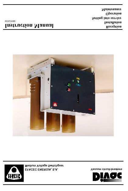
4 2. General 2.1 Introduction The Divac type vacuum circuit-breakers are indoor equipment suitable for normal operating conditions as individual units for fixed installation or as Withdrawable units for air- insulated switchboards. Due to their vacuum switching principle and simple and robust construction, Divac type circuit-breakers have high reliability and long life expectancy. The Divac range uses a stored energy spring operating mechanism. The basic version is fitted with a manual spring charging device or with an optional charging motor, making the breaker suitable for auto-reclosing and also for multishot auto-reclosing fast cycles. 2.2 Standards Divac circuit-breakers were specially designed to comply with IEC 56 and IEC 694 standards. fig. 1 - Divac circuit-breakers (fixed installation version) 3. Technical data 3.1 Designation Divac circuit-breakers range is designated by the common name Divac followed by three specification characters. Example: 6 1 B rated current breaking current rated voltage 3
5 3.2 Electrical ratings and dimensions Rated Rated insulation level Rated Short- Breaker Height Depth Width Distance voltage Power current circuit designation between Lighting frequency breaking (A) (P) (L) poles pulse ( 1 min.) current (EP) kv kv kv A ka mm mm mm mm 630 Divac 41 B Divac 41 D 630 Divac 42 B Divac 42 D Divac 42 E 2000 Divac 42 F 1250 Divac 43 D ,5 Divac 43 E Divac 43 F 630 Divac 51 B Divac 51 D 630 Divac 52 B Divac 52 D 17, Divac 52 E 2000 Divac 52 F 1250 Divac 53 D ,5 Divac 53 E Divac 53 F 630 Divac 61 B Divac 61 D 630 Divac 62 B Divac 62 D Divac 62 E 2000 Divac 62 F 1250 Divac 63 D ,5 Divac 63 E Divac 63 F Making current (ka peak) 2,5 times the breaking current for all the range Short withstand current equal to the breaking current held for 1 or 3 seconds Operating cycles O - 3 min - CO - 3 min - CO O - 0,3 s - CO - 15 s - CO - 15s - CO 4
6 fig. 2 - Divac fixed installation versions A, ka, up to 24 kv. A fig. 3 - Divac fixed installation versions A, 31,5 ka, up to 24 kv 5
7 3.3 Fixation (top views) EP EP EP EP entrada de circuitos auxiliares entrada de circuitos auxiliares fig. 4-1: Divac fixed inst. version A, fig. 4-2: Divac fixed installation version A, ka, up to 17,5 kv ka, 24 kv. M10 x 20 ISO entrada de circuitos auxiliares fig. 4-3: Divac fixed installation version A, 31,5 ka, up to 24 kv. fig. 4-4: fixation detail 3.4 Connecting terminals M16 M16 M12 Ø 16,1 mm Ø 16,1 mm máx. 36 mm fig.5-1 : up to 630 A - 16 ka fig. 5-2 : up to 1250 A - 25 ka fig.5-3 : up to 2000 A ka 6
8 3.5 Standard equipment and options Divac circuit-breakers with manual operating mechanism Opening and closing 1 mechanical push-buttons Opening solenoid Mechanical switch position indicator Mechanical closing springs charging condition indicator Auxiliary switches for shunt release and switch position signalling Divac circuit-breakers with recharging motor (in addition to manual recharging mechanism) Closing springs electrical recharging motor with protection fuses Closing solenoid Anti-pumping relay Auxiliary switches for recharging motor control Other options available Undervoltage tripping solenoid Additional opening solenoid Magnetic striker release device, working without any auxiliary energy source Mechanical switching operation counter Auxiliary switches for closing springs status indication Additional breaker position auxiliary switches Connection terminals Standard colours RAL 7032 (frame ) and RAL 7026 (front cover ) 3.6 Switching times and power consumption Divac circuit-breakers switching times (typical values ) Opening time Arcing time Breaking time Making time < 50 ms < 20 ms < 70 ms < 50 ms Closing springs charging time < 15 s Equipment power consumption VA/W Voltage range Charging motor % Un Closing solenoid % Un Opening solenoid % Un Undervoltage tripping solenoid: - switching - permanent % - 70% Un 7
9 3.7 Operating conditions Divac type vacuum circuit-breakers are indoor equipment suitable for fixed installations or Withdrawable units for air- insulated switchboards. The indoor installation place should not have excessive moisture, dust or corrosive fumes and sufficient heat and air circulation should be provided to prevent condensation. Satisfactory performance of these breakers is contingent upon proper application in accordance with IEC 694 standard: Ambient temperature range -5 to + 40 C Maximum 24-hour average temperature + 35 C Maximum installation altitude above sea level Maximum average relative humidity measured - during 24 hours - during a month 1000 m 95% 90% For any other operating conditions, please consult the manufacturer. 4. Description and operation 4.1 Closing and opening operations : manual operation, using front cover mechanical push-buttons - see fig. 6: - Closing: press the green push-button. - Opening: press the red push-button. electrical operation, using opening solenoid and optional closing solenoid ) Mechanical closing push-button 2) Mechanical opening push-button 3) Withdrawable manual charging lever 4) Switch position mechanical indicator 5) Closing springs charging condition mechanical indicator 6) Optional closing push-button key interlock 7) Optional mechanical switching operation counter 4 5 fig. 6 -front cover 7 1 On request, closing push-button can be interlocked with a key. 8
10 4.2 Closing springs (re)charge Divac circuit-breakers are fitted with a standard closing springs manual (re)charge mechanism. Manual charging operation is made applying a pumping action with the charging lever, as in fig. 7. After about ten pumping movements, the (re)charging will be completed and signalised by the charging condition indicator and lever action stops to charge closing springs. fig. 7- manual (re)charge In order to perform an automatic reclosing sequence, closing springs must be previously charged. In manual versions, a hand -made (re)charge operation is necessary. After each closing operation, automatic closing springs recharge is made in versions fitted with a recharging motor, making these versions specially suitable for auto-reclosing sequences. If power failure occurs during automatic recharge, manual recharge could be performed to complete the operation. The completion of each (re)charge operation is signalised by the charging condition indicator 10
11 4.3 Front cover indicators The possible operating mechanism positions and circuit-breaker switch positions, as well as front cover indicators meaning, are presented in Table I: Position operating mechanism switch indicator closing springs charging indicator electrical position A Breaker Open Closing springs discharged Breaker Open B Closing springs charged C Breaker Closed Closing springs discharged D Breaker Closed Closing springs charged Table I Whenever fitted, and after each cycle completion, mechanical switch counter increases by one the prior reading. 11
12 4.4 Structure of the poles Each pole is formed by an epoxy resin insulating column-form envelope (1), fixed to the breaker base frame with screws (2).The circuit-breaker live parts, including the vacuum interrupters (3), are housed inside the envelope, eliminating the possibility of phase to phase and phase to ground arcing faults. The main circuit is formed by the upper (4) and lower (5) terminals, the vacuum interrupter and rigid (6) and flexible connectors (7). The vacuum interrupters make use of the excellent dielectric properties of high vacuum, being able to ensure high insulation levels for very short contact distances. In order reduce to a negligible value the contact erosion, vacuum interrupters fitted in Divac circuit breakers produces an axial magnetic field between the contact surfaces, causing the rotation and diffusion of electrical arcs. The opening spring (8) and contact pressure spring (9) are mounted under the lower terminal. The insulating rod (10) transmit to the vacuum interrupters the operating mechanism switching motion Operating mechanism structure fig. 8 The Divac range uses a stored energy spring operating mechanism. The opening and closing operations are made applying the springs stored energy to the breaker main shaft, connected to the vacuum interrupters moveable contacts. Depending on the version, after each closing operation, closing springs (1) charge can be made either manually, using the charging lever (2), or automatically by an optional charging motor (3). The opening (4) and closing (5) shunt solenoids allow the electrical remote breaker operation, while the front panel push-buttons always provide a direct mechanical operation. The mechanical switch position indicator (6) and the charging condition indicator (7) provide information about the circuit breaker condition, fig.9 12
13 4.5.1 Operating mechanism positions According Tab. I, the operating mechanism has four possible positions: closing spring A) Breaker open B) Breaker open, closing springs discharged closing springs charged C B A D C) Breaker closed, D) Breaker closed, closing springs discharged closing springs charged fig
14 4.6 Operation Charging of closing springs In figure 10-A) the breaker is presented in the opened position with closing springs discharged.. In this situation, the operation of the closing or opening push-buttons does not make any change in the operating mechanism position. To make a closing operation, closing springs must be previously charged. After a closing operation, the (re-)charging sequence will be automatic performed in versions fitted with a charging motor. In the manual type versions, the required charging by hand is made applying a pumping action with the charging lever, as in fig. 7. After about ten pumping movements, the (re-) charging will be completed and signalised by the charging condition indicator. In either versions during the (re-)charge operation, the closing springs charging mechanism transmits the (re-)charging movement to the main cam (3) by a lever with an unidirectional roller-bearing that prevents the rotation of the main cam in a direction opposite to the (re-)charge one (B) when the closing springs are being charged. When main cam reach its final position, the charging condition indicator provide the charged closing springs information, while a micro-switch cut off the charging motor operation. Closing springs charge condition is maintained by the roller (6) and cam (8), while opening latch is recharged. An immediate closing operation is possible, as the operating mechanism has now closing springs charged (fig.10-b) Closing The closing push-button or the closing solenoid operation will cause closing latch (7) rotation in (A) direction, freeing cam (8) and the closing springs stored energy, that will be applied as a torque in main cam (3). As a result, this will rotate in (B) direction, making through connection (5) main shaft rotate in (D) direction, leading the breaker to a closed position and charging the opening latch (see fig.10-c) Opening The opening push-button or the opening solenoid operation will cause opening latch (2) rotation in (C) direction, freeing cam (4) together with connection (5). The opening and contact pressure springs stored energy will cause the main shaft rotation in an opposite to (D) direction, making the breaker open Trip-free feature The Divac operating mechanism will always make an opening command prior to a closing one (tripfree feature). If during the closing process an opening command takes place, the opening and contact pressure stored energy free by opening latch (2) will take the breaker to an opened position. 14
15 4.6.5 Automatic reclosing sequence In order to perform an automatic reclosing sequence, closing springs must be previously charged. After each closing operation, automatic closing springs recharge is made in versions fitted with a recharging motor, while manual versions need a hand-made recharge operation. After each opening operation, charged closing springs condition is kept in order to allow an immediate reclosing. 4.7 Safety disposals Mechanical safety Opening commands have always priority over closing ones (trip-free feature): if an opening command is being executed, any attempt to make the breaker close will lead to closing springs discharge without moving vacuum interrupter contacts Electromechanical safety Depending on circuit breaker switch position, validation of opening or closing solenoid commands is made by the rotating switches connected to main shaft, thus preventing closing solenoid operation if the breaker is already closed and opening solenoid operation if breaker is already opened Auxiliary voltage connections Auxiliary voltage connectors are provided in order to allow external commands. In Normacel panel Withdrawable versions, special plug-type connectors are used Normacel panel withdrawable versions Trying to insert or withdraw a closed circuit-breaker placed in a Normacel panel will cause the breaker immediate opening, thus avoiding accidental interruptions or connections of the main circuit (see Normacel Instructions Manual). 15
16 5. Receipt, Transport and Storage 5.1 Receipt The Divac circuit-breakers are mechanically and electrically inspected before despatch, in the opened position with discharged closing springs ( see Tab. I- A). They are supplied individually, sealed in plastic film and wood pallets, providing good transport and storage conditions. During goods receipts the pallet must bee untouched Nameplate Check in the nameplate the compliance between the order and the received material. 5.2 Transport The circuit-breaker should not be unpacked before installation, in order to profit from the mechanical protection of the package Use always the wooden pallet during handling. Lifting tackle must never catch on the breaker poles or the operating mechanism. The Divac circuit-breakers are supplied with lifting tools in the points marked with the symbol In fixed installation versions, after unpacking, move the circuit-breaker to the installation place using the wheels. 5.3 Storage If Divac circuit-breaker have to be stored prior to use, it should be done in the despatch positioncircuit-breaker switched off with closing springs discharged ( as Tab. I-A). Circuit-breaker should be stored in the original packing. Store indoors, in a dry, dust-free, and well ventilated room, avoiding direct sunlight. 16
17 6. Installation 6.1. Preparatory activities The construction works in the room must be finished, being the place dry, dust-free and having a good ventilation. Connect the main terminals only after the circuit-breaker fixation in the normal service position. Make a circuit-breaker general cleaning removing any contamination, specially on insulating parts. Check the integrity of primary and secondary connections and earth conductor connection Installation process ( fixed versions ) Prior to begin circuit-breaker installation, check if the primary voltage is off The operations are the following : Circuit-breaker fixation in the normal service position ( see figs. 2, 3 e 4 ), using tensile class 8.8 screws with correct thread size and conical spring washers. Apply the recommended rated tightening torque. Connect the earth conductor with recommended section to the circuit-breaker frame, using terminal with symbol ( ) - see figs. 2 e 3. In the Normacel panel Withdrawable version, the earth connection is always done when the breaker is in the panel. Connect the main terminals, avoiding any permanent tension or pressure forces exerted, for example, by the conductor bars.use tensile class 8.8 screws with conical spring washers for fastening conductor bars together. After removing the front panel, insert the auxiliary conductors in the operating mechanism compartment using the hole ( see figs. 4-1 a 4-3) in the frame base. Connect conductors according the electrical wiring scheme supplied with the circuit-breaker. The auxiliary conductors must have the necessary section and insulation for the fixed installation ( test voltage 3 kv ). Outside circuitbreaker, the auxiliary circuits should be protected and installed in gutters with an earth connection. Put the operating mechanism front cover in the original position 17
18 6.3. Commissioning - Preparatory checking Check the tightness of the connections. Check the primary and secondary connections and the earthing conductor connections. Manually charge the closing springs using the recharging handle. Perform a manual closing and opening operation on the circuit-breaker, using the front panel pushbuttons. Observe the compliance between the operation and the switch position and closing spring charge conditions indicators ( see Tab. I). Note: If the circuit-breaker is equipped with under voltage trip solenoid, it is necessary to attach the solenoid core in the spring compressed position, until the auxiliary circuits voltage be on, otherwise the circuit-breaker will open immediately after a closing operation. Check if the auxiliary circuits voltage is the same as the equipment. Connect the auxiliary voltage circuits. In versions fitted with a recharging motor, closing springs automatically recharging will be performed whenever closing are discharged.. Check for automatically recharging performance, making a closing and opening sequence. Check for opening and closing solenoids performance. After the successful completion of these preliminary checkings, the circuit-breaker is ready for service. 18
19 7. Inspection and Maintenance Maintenance work may only be performed in a careful manner by trained personal familiar with the characteristics of the circuit-breaker and safety regulations. Before any circuit-breaker maintenance activity, observe the following procedure: Ensure that circuit-breaker is switched off with closing springs discharged, as Tab.I-A (in motorised versions disconnected all auxiliary voltage sources, to prevent automatic recharge ). In fixed installation versions, disconnected the main and auxiliary voltage sources. For the Normacel panel versions, remove the circuit-breaker from the switchgear cubicle. 7.1 General Divac circuit-breakers are characterised by a high reliability and long life expectancy due to their simple and robust construction. As Divac vacuum circuit-breakers need low operation energy, the operating mechanism has low wear and that means a long useful life and longer intervals between maintenance inspection. In normal operating conditions, the poles, including the vacuum interrupters, are maintenance free 7.2 Electrical working life The vacuum interrupters electrical working life depends on the performed operating cycles number (n) and on the breaking current, as fig Number of operations (n) Breaking current (A) fig.11 19
20 7.3 Periodic inspection A long working life and the interval of inspections, are determined by operating conditions, switching frequency, number of short-circuit breaking operations and environmental influences. If the installation or operating conditions are more severe than the ones stated in this manual, the inspection interval must be shortened. To have the guaranty of a good pole insulation, it will be necessary make a periodic careful cleaning, removing all the surface contamination. The periodic inspections and preventive maintenance intervals, in a normal utilisation, are the following: After 1 year or switching operations Circuit-breaker: - Visual inspection, checking damage signals or corrosion - Carefully cleaning with a soft dry cloth, removing all the surface dust specially in the poles Operating mechanism : - Remove front cover - Visual inspection, checking for excessive wear in the mechanical components - Check the condition of lubrication Every 5 years or after switching operations Circuit-breaker: - Visual inspection, checking for damage or corrosion signals - Carefully cleaning of poles surface, removing all the dust from the poles with a soft dry cloth Operating mechanism: - Remove frontal cover - Inspection, checking the wear in the mechanical components - Clean with a cloth soaked in white-spirit the operating mechanism before lubrication - Lubricate the points marked in fig.12. After 20 years or after switching operations - Possible replacement of highly stressed parts. - Possible replacement of vacuum interrupters. For a more demanding degree of operations (e.g operations), periodic inspections and preventive maintenance intervals will be defined according each request. 20
21 7.4 Lubrication Lubricate with a thin layer of Mobilgrease Special from Mobil the points marked with in fig.12. fig Replacement parts The parts, signalled with * at the table, replacement must be performed by EFACEC Medium Voltage Switchgear Division - After-Sales department personnel. Orders for replacement parts request the following information: All the information of circuit-breaker nameplates (type of circuit-breaker, serial number, work order,etc.) Reference number ( like Tab. II) and desired parts quantity Voltage source value and kind of current (d.c. or a.c.) of auxiliary circuits Code Description 1 * Complete pole 2 * Closing solenoid 3 * Opening solenoid 4 * Additional opening solenoid 9 Undervoltage tripping solenoid (AFT) 6 Recharging motor 7 Recharging motor fuse 8 Anti-pumping relay 9 Auxiliary contacts block 10 * Damper 11 Closing interlock 12 Auxiliary contacts Tab. II - Replaceable parts 21
22 EFACEC AMT Aparelhagem de Média Tensão, S.A. Porto Arroteia Leça do Bailio Apartado S.Mamede de Infesta Codex Portugal Telef: (+351) Fax: (+351) Exportação Arroteia Leça do Bailio Apartado S.Mamede de Infesta Codex Portugal Telef: (+351) Fax: (+351) Lisboa Rua da Garagem, 1 Apartado 527 Carnaxide 2796 Linda-a-Velha Codex Portugal Telef: (+351) Fax: (+351)
VD4 Installation and service instructions kv A ka
 Medium voltage products VD4 Installation and service instructions 12... 36 kv - 630... 3150 A - 16... 50 ka Index For your safety! 1 I. Introduction 2 II. Programme for environmental protection 2 1. Packing
Vacuum Circuit-Breakers, Type HVX kv, of cassette design, cassette with motor drive
 Vacuum Circuit-Breakers, Type HVX 12 24 kv, of cassette design, cassette with motor drive Operating Instructions No. 531 321, Edition 09/00 Table of Contents 1 General 4 1.1 Operating Conditions 4 2 Design,
Air-insulated withdrawable switchboard. Medium Voltage Switchgear. Dispatch Installation Start-up Operation Maintenance. Instruction Manual MVRD30024A
 Air-insulated withdrawable switchboard Medium Voltage Switchgear Instruction Manual MVRD30024A Dispatch Installation Start-up Operation Maintenance Contents 1. Description 1.1 Safety Precautions..... Page
VD4. Installation and service instructions kv A ka
 VD4 Installation and service instructions 12... 24 kv - 630... 2500 A - 16... 31.5 ka For your safety! Make sure that the installation room (spaces, divisions and ambient) is suitable for the electrical
SION Vacuum Circuit-Breakers. Answers for energy. Medium-Voltage Equipment Selection and Ordering Data. Catalog HG
 Medium-Voltage Equipment Selection and Ordering Data Catalog HG 11.0 008 Answers for energy. R-HG11-17.tif Siemens HG 11.0 008 Contents Contents Page SION Vacuum Circuit-Breakers Description General Construction
SION Vacuum Circuit-Breakers. Answers for energy. Medium-Voltage Equipment Selection and Ordering Data. Catalog HG
 Medium-Voltage Equipment Selection and Ordering Data Catalog HG 11.02 2011 Answers for energy. R-HG11-172.tif 2 Siemens HG 11.02 2011 Contents SION Vacuum Circuit-Breakers Medium-Voltage Equipment Catalog
User manual W-VACi. W-VACi 12 / 17.5 / 24 kv IEC Vacuum Circuit Breakers
 User manual W-VACi W-VACi 12 / 17.5 / 24 kv IEC Vacuum Circuit Breakers 65A7355H01 Rev.04 January 2013 www.eaton.com 2 Table of contents 1 Safety... 5 1.1 Safety precautions...5 1.2 Safety practices...5
General. Main electric circuits Fuses compartment Operating mechanisms Cables connection compartment
 General The switchgear must be suitable for 36 kv rated voltage and specifically conceived for the secondary distribution substations in M.V. with either ring or radial type networks. The switchgear must
Voltage Rated operating voltage [kv] Rated power frequency withstand voltage [kv] Rated lightning impulse withstand voltage [kv]
![Voltage Rated operating voltage [kv] Rated power frequency withstand voltage [kv] Rated lightning impulse withstand voltage [kv]](/thumbs/80/82203973.jpg "Voltage Rated operating voltage [kv] Rated power frequency withstand voltage [kv] Rated lightning impulse withstand voltage [kv]") BasisBlock MC 1 Standards and Regulations IEC 62271-200 ; VDE 0671-200 ; BS EN 62271-200 Technical Data MC1-12 MC1-24 Voltage Rated operating voltage [kv] 12 24 Rated power frequency withstand voltage
BasisBlock MC 1 Standards and Regulations IEC 62271-200 ; VDE 0671-200 ; BS EN 62271-200 Technical Data MC1-12 MC1-24 Voltage Rated operating voltage [kv] 12 24 Rated power frequency withstand voltage
3AK OPERATING INSTRUCTIONS. Vacuum circuit-breaker module 3AK1 and 3AK3
 3AK Vacuum circuit-breaker module 3AK1 and 3AK3 OPERATING INSTRUCTIONS Order no.: 9229 9923 176 0B Ordering location: IC LMV LP PO P C41 AG 09.2013 en Siemens AG 2006. All rights reserved. For your safety
GE Consumer & Industrial Power Protection. New. SecoGear kV Metal-clad Switchgear. GE imagination at work
 GE Consumer & Industrial Power Protection New SecoGear 12-24kV GE imagination at work General SecoGear metal-clad switchgear is designed and manufactured with advance technology and has been comprehensively
Submersible Vacuum Fault Interrupters
 Submersible Vacuum Fault Interrupters UG Distribution Medium Voltage Vacuum Fault Interrupters Functional Specification Guide PS024002EN Functional Specification for 2.4kV to 17.5kV UG Distribution Medium
Outdoor live tank vacuum circuit breaker Type OVB-VBF for 24/36/40.5 kv applications
 Outdoor live tank vacuum circuit breaker Type OVB-VBF for 24/36/40.5 kv applications ABB a global leader ABB is a global leader in power and automation technologies that enable utility and industry customers
Air-insulated switchgear UniGear type ZS1
 Air-insulated switchgear UniGear type ZS1 ABB Power Technologies / 1-7074 D 12-03-2003 - Air-insulated switchgear UniGear type ZS1 ABB Power Technologies / 2-7075 D 1 2-03-2003 - Rated voltage kv 12 17.5
High-Voltage Circuit-Breakers 3AP1/ kv up to 550 kv. Power Transmission and Distribution
 High-Voltage Circuit-Breakers AP/ 7.5 kv up to 550 kv Power Transmission and Distribution The AP/ High-Voltage Circuit-Breakers Now Applicable for 550 kv Decades of our experience in high-voltage switching
GE Industrial Solutions. User/Installation Manual for 4.76kV -15kV SecoBloc
 GE Industrial Solutions User/Installation Manual for 4.76kV -15kV SecoBloc Index General Scope...3 Standards...3 Operating conditions...3 Technical specification...3 Basic structure Features...4 Operation...4
PIX-H Metal-clad switchgear up to 17.5kV
 AIR INSULATED SWITCHGEAR PIX-H Metal-clad switchgear up to 17.5kV for high rated applications Technical Specifications AREVA T&D Summary - Technical description... 3 - Standards... 6 - PIX in detail...
AIR INSULATED METAL ENCLOSED SWITCHGEAR AND CONTROLGEAR
 AIR INSULATED METAL ENCLOSED SWITCHGEAR AND CONTROLGEAR ANGLER SWITCHING DEVICES CONTENTS 1. General 2. Switchgear Types - Switch Disconnector - Disconnector 3. Cubicle Types - Cubicle with Switch Disconnector
EISHO TEK. Vacuum Circuit Breaker
 EISHO TEK Vacuum Circuit Breaker TYPE:SV1-12 INSTRUCTION MANUAL Operation and Maintenance Version TAIWAN CALSONIC SAFETY PRECAUTIONS For safety reason, this equipment should be handled by personnel who
AIR INSULATED EXTENDABLE SWITCHGEAR UP TO 12KV GUIDE
 AIR INSULATED EXTENDABLE SWITCHGEAR UP TO 12KV GUIDE Certificate Number FM35831 APPLICATION Typical Uses and Classification The MSGair switchgear is used in transformer and switching substations mainly
HVX. Vacuum circuit-breaker 12-17,5 kv ( 2500 A, 31,5 ka) Installation Operation Maintenance No. DRC NTV 142. Technical instruction.
 Installation Operation Maintenance No. DRC NTV 142. Technical instruction.") MEDIUM VOLTAGE SWITCHING DEVICE HVX Vacuum circuit-breaker 12-17,5 kv ( 2500 A, 31,5 ka) Installation Operation Maintenance No. DRC NTV 142 Issue 02/10 Technical instruction AREVA T&D IMPORTANT NOTE The
MEDIUM VOLTAGE SWITCHING DEVICE HVX Vacuum circuit-breaker 12-17,5 kv ( 2500 A, 31,5 ka) Installation Operation Maintenance No. DRC NTV 142 Issue 02/10 Technical instruction AREVA T&D IMPORTANT NOTE The
TGI Vacuum Circuit-Breaker Air isolator Earthing switch
 TGI Vacuum Circuit-Breaker Air isolator Earthing switch PATENT Versatile Visible isolation Simple Removable Index 3 in 1 2 Simple and versatile 4 Operations sequence ON Commissioning 8 Operations sequence
Vacuum Circuit Breaker (Vehicle)
") Vacuum Circuit Breaker (Vehicle) Type 5 HVU-250 4.76kV Instructions Installation Operation Maintenance SGIM-9998A Hazardous voltages and high-speed moving parts. Will cause death, serious injury or equipment
Vacuum Circuit Breaker (Vehicle) Type 5 HVU-250 4.76kV Instructions Installation Operation Maintenance SGIM-9998A Hazardous voltages and high-speed moving parts. Will cause death, serious injury or equipment
EMPAC Metal enclosed capacitor bank for wind applications
 EMPAC Metal enclosed capacitor bank for wind applications Introduction The EMPAC is a Metal Enclosed Capacitor Bank suitable for voltages between 1 kv and 36 kv for reactive compensation in MV networks
Vacuum Circuit Breakers (Vehicle) Type HKR 7.5kV to 15kV. Instructions Installation Operation Maintenance SGIM-9928C
 Type HKR 7.5kV to 15kV. Instructions Installation Operation Maintenance SGIM-9928C") Vacuum Circuit Breakers (Vehicle) Type HKR 7.5kV to 15kV Instructions Installation Operation Maintenance SGIM-9928C Hazardous voltages and high-speed moving parts. Will cause death, serious injury or equipment
Vacuum Circuit Breakers (Vehicle) Type HKR 7.5kV to 15kV Instructions Installation Operation Maintenance SGIM-9928C Hazardous voltages and high-speed moving parts. Will cause death, serious injury or equipment
Metal Clad Air Insulated Switchgear
 Metal Clad Air Insulated Switchgear 1/ SecoGear Metal Clad Switchgear Features Fully metal-clad Equipped with Embedded pole VCB Full Front access (can be installed against wall) Perfect interlocking system
VD4/R - VD4/L - VD4/UniAir - VD4/UniMix
 VD4/R - VD4/L - VD4/UniAir - VD4/UniMix Installation and maintenance instructions 12... 24 kv - 630... 1250 A - 12... 25 ka 1 For your safety! Make sure that the installation room (spaces, divisions and
MEDIUM VOLTAGE CE-B36 METAL CLAD SWITCHBOARDS. CE - B36 - C - en - REV
 CE - B36 - C - en - REV.00 2011.9 EDIU VOLTAGE EDIU VOLTAGE APPLICATION CE-B etal Clad switchboards are designed for use in public and industrial distribution system up to 36kV for the operation and protection
Longest Life Product for Electric Furnace Applications! 100,000 Operations No Routine Maintenance Required!
 DB 750-205 January 2007 Supercedes: December 2006 Now available with Vacuum Interrupter Monitor VBT Switch 15kV - 69kV VBU-T Switch 69kV - 230kV Longest Life Product for Electric Furnace Applications!
MEDIUM VOLTAGE CE-B METAL CLAD SWITCHBOARDS. CE - B - C - en - REV
 MEDIUM VOLTAGE MEDIUM VOLTAGE APPLICATION CE-B Metal Clad switchboards are designed for use in public and industrial distribution system up to 24kV for the operation and protection of lines, generators,
MEDIUM VOLTAGE CE-B METAL CLAD SWITCHBOARDS. CE-B-C-en-REV
 CE--C-en-REV.04 2016.1 MEDIUM VOLTAGE MEDIUM VOLTAGE APPLICATION CE- Metal Clad switchboards family are designed for use in public and industrial distribution system up to 40,5kV for the operation and
Medium Voltage Distribution PIX. Air Insulated Switchgear up to 24 kv PARS TABLEAU
 Medium Voltage Distribution PIX Air Insulated Switchgear up to kv PIX Air Insulated Switchgear up to kv The PIX system has been designed in accordance with international (IEC) standards, and gives an optimal
MV Air Insulated Switchgear TAP17. Technical Data TGOOD
 MV Air Insulated Switchgear TAP17 Technical Data TGOOD 2017.1 Operating environmental conditions Place of installation: Indoor or outdoor Ambient temperature: 25 ~ +40 (higher or lower temperature optional)
MEDIUM VOLTAGE SWITCHING DEVICE. Vacuum circuit-breaker 17,5 kv (> 2500 A / 50 ka) Installation Operation Maintenance
 Installation Operation Maintenance") 0 MEDIUM VOLTAGE SWITCHING DEVICE HVX Vacuum circuit-breaker 17,5 kv (> 2500 A / 50 ka) Installation Operation Maintenance HVX No. AGS 531 461-01 Edition 06/07 Technical instruction AREVA T&D AREVA T&D
0 MEDIUM VOLTAGE SWITCHING DEVICE HVX Vacuum circuit-breaker 17,5 kv (> 2500 A / 50 ka) Installation Operation Maintenance HVX No. AGS 531 461-01 Edition 06/07 Technical instruction AREVA T&D AREVA T&D
HVX Series. 36 kv Medium Voltage Vacuum circuit breaker. Make the most of your energy SM. Medium Voltage Distribution Catalogue 2015
 Medium Voltage Distribution Catalogue 205 HVX Series 36 kv Medium Voltage Vacuum circuit breaker Fixed, middle rolling and floor rolling ranges of circuit breaker and disconnector Make the most of your
NXPLUS C Single busbar. Maintenance-free for lifetime
 NXPLUS C Single busbar Maintenance-free for lifetime Energy Distribution Welcome! Page 2 Content Overview Technical data Typicals Panel design Circuit-Breaker panel Busbar Operation Metering Low-voltage
KYN28A-12 (GZS1) A.C METALCLAD REMOVABLE SWITCHGEAR FOR INDOOR USE CHINATCS
 A.C METALCLAD REMOVABLE SWITCHGEAR FOR INDOOR USE CHINATCS") KYN28A-12 (GZS1) A.C METALCLAD REMOVABLE SWITCHGEAR FOR INDOOR USE CHINATCS 2001.09 KYN28A-12 (GZS1) A.C Metalclad Removable Switchgear for Indoor Use --------The Leader in Switchgear Up to 12kV 1. The
KYN28A-12 (GZS1) A.C METALCLAD REMOVABLE SWITCHGEAR FOR INDOOR USE CHINATCS 2001.09 KYN28A-12 (GZS1) A.C Metalclad Removable Switchgear for Indoor Use --------The Leader in Switchgear Up to 12kV 1. The
Using new Magnetically Actuated Vacuum Interrupter technology for safe and reliable medium voltage circuit breaker switching in mines
 Using new Magnetically Actuated Vacuum Interrupter technology for safe and reliable medium voltage circuit breaker switching in mines Abstract: The development of the magnetically actuated vacuum interrupter
Vacuum Circuit Breakers (Vehicle)
") Vacuum Circuit Breakers (Vehicle) Type 5 HVR 4.16kV Instructions Installation Operation Maintenance SGIM-9948D Hazardous voltages and high-speed moving parts. Will cause death, serious injury or equipment
Vacuum Circuit Breakers (Vehicle) Type 5 HVR 4.16kV Instructions Installation Operation Maintenance SGIM-9948D Hazardous voltages and high-speed moving parts. Will cause death, serious injury or equipment
Medium voltage products UniSec DY800 New 24 kv air-insulated medium voltage switchgear to e-distribuzione specifications
 Medium voltage products UniSec Y800 New 24 kv air-insulated medium voltage switchgear to e-istribuzione specifications UniSec Y800 ubicles available Unit e-istribuzione specifications (Ed. 4) UniSec IS/1
33KV INDOOR SWITCHGEAR
 33KV INDOOR SWITCHGEAR September 2017 Engineering Department WEST BENGAL STATE ELECTRICITY TRANSMISSION COMPANY LIMITED Regd. Office: VidyutBhawan, Block DJ, Sector-II, Bidhannagar, Kolkata 700091. CIN:
HD4-LMT. MV SF6 Circuit Breaker Installation and Service Instructions kv 1,250 A 31.5 ka
 HD4-LMT MV SF6 Circuit Breaker Installation and Service Instructions 17.5 kv 1,250 A 31.5 ka For your safety Make sure that the installation room ( i.e. spaces, divisions and the atmosphere ) are suitable
Fixed-Mounted Circuit-Breaker Switchgear Type 8DA and 8DB up to 40.5 kv, Gas-Insulated
 www.siemens.com/medium-voltage-switchgear Fixed-Mounted Circuit-Breaker Switchgear Type 8D and 8DB up to 0.5 kv, Gas-Insulated Medium-Voltage Switchgear Catalog H 35.11 201 nswers for infrastructure and
PATENT PENDING. Phone: (877) Operation and Service Manual
 Operation and Service Manual") PATENT PENDING Phone: (877) 544-2291 Operation and Service Manual 2 IMPORTANT NOTICE This document contains information intended to aid in the proper installation, operation, and maintenance of the product
PATENT PENDING Phone: (877) 544-2291 Operation and Service Manual 2 IMPORTANT NOTICE This document contains information intended to aid in the proper installation, operation, and maintenance of the product
CPG.0 Single busbar gas-insulated cubicles
 MV Switchgear Primary Distribution CPG.0 Single busbar gas-insulated cubicles Up to 36 kv CPG System The quality of products designed, manufactured and installed by Ormazabal is underpinned by the implementation
Specification for 70mm pole pitch Air circuit breaker up to 1600 A
 Specification for 70mm pole pitch Air circuit breaker up to 1600 A Protective device for low voltage electrical installation Last update :2011-07-08-1 - Table of contents: 1 General...3 2 Compliance with
SafeGear Motor Control Center Arc Resistant Metal-Clad Construction Brochure
 2017 SafeGear Motor Control Center Arc Resistant Metal-Clad Construction Brochure SafeGear Motor Control Center Arc resistant Metal-Clad construction Brochure Table of Contents 1. Description 1 1 2. SafeGear
Instruction Booklet for the Installation, Operation and Maintenance of Type 5-15 kv VCP-WG Vacuum Circuit Breaker 4000A MiniMod
 Instruction Booklet for the Installation, Operation and Maintenance of Type 5-15 kv VCP-WG Vacuum Circuit Breaker 4000A MiniMod Eaton Corporation Moon Twp, PA. U.S.A. 15108 1 INTRODUCTION READ AND UNDERSTAND
SYSclad switchboard equipped with draw out type vacuum circuit breaker closed dooroperationoperation. SYSclad 12 17,5kV A.
 SYSclad switchboard equipped with draw out type vacuum circuit breaker closed dooroperationoperation 630 3150A SYSclad 12 17,5kV 16 31,5kA Generalities SYSclad is a medium voltage switchboard metal clad
Type 38-3AH3 38 kv vacuum circuit breaker instruction manual. Installation operation maintenance E50001-F710-A238-V1-4A00. Answers for energy.
 Type 38-3AH3 38 kv vacuum circuit breaker instruction manual Installation operation maintenance E50001-F710-A238-V1-4A00 Answers for energy. Hazardous voltages and high speed moving parts. Will cause death,
HVX Vacuum circuit-breaker kv ( 2500 A, 40 ka)
") MEDIUM VOLTAGE SWITCHING DEVICE HVX Vacuum circuit-breaker 12-24 kv ( 2500 A, 40 ka) Installation Operation Maintenance 0 HVX No. AGS 531 301-01 Edition 07/07 Technical instruction AREVA T&D AREVA T&D
MEDIUM VOLTAGE SWITCHING DEVICE HVX Vacuum circuit-breaker 12-24 kv ( 2500 A, 40 ka) Installation Operation Maintenance 0 HVX No. AGS 531 301-01 Edition 07/07 Technical instruction AREVA T&D AREVA T&D
24 k B788 ELEKTROTECHNISCHE WERKE FRITZ DRIESCHER & SÖHNE GMBH
 788 Instructions for Installation, Operation and Maintenance for DRIESCHER - Air - Insulated Medium - Voltage Compact Switchgears for Substations Rated voltage 12 kv and 24 kv Rated current 630 A 24 k
3TM Vacuum Contactors
 Catalog Extract HG 11.23 Edition 2016 Catalog Extract Medium-Voltage Equipment siemens.com/3tm R-HG11-343.psd 2 Siemens HG 11.23 2016 Contents Medium-Voltage Equipment Catalog Extract HG 11.23 2016 Contents
Vacuum Circuit Breakers (Vehicle)
") Vacuum Circuit Breakers (Vehicle) Type DTR 7.5kV to 15kV Instructions Installation Operation Maintenance SGIM-9938B Hazardous voltages and high-speed moving parts. Will cause death, serious injury or equipment
Vacuum Circuit Breakers (Vehicle) Type DTR 7.5kV to 15kV Instructions Installation Operation Maintenance SGIM-9938B Hazardous voltages and high-speed moving parts. Will cause death, serious injury or equipment
W-VACi IEC medium voltage vacuum circuit breakers 12 kv, 17,5 kv and 24 kv
 This is a photographic template your photograph should fit precisely within this rectangle. W-VACi IEC medium voltage vacuum circuit breakers 12 kv, 17,5 kv and 24 kv Mostapha Azzahimi Product Manager
VD4 Installation and service instructions 36 kv A ka
 Medium Voltage Products VD4 Installation and service instructions 36 kv -... 2500 A - ka Index I. Introduction 3 II. Programme for environmental protection 3 1. Packing and transport 3 2. Checking on receipt
SUBSTATION VACUUM CIRCUIT BREAKER (15.5KV)
") SUBSTATION VACUUM CIRCUIT BREAKER (15.5KV) For more than four decades, Myers Power Products has led the switchgear market in quality for the electric industry, delivering highly reliable products for utilities
SUBSTATION VACUUM CIRCUIT BREAKER (15.5KV) For more than four decades, Myers Power Products has led the switchgear market in quality for the electric industry, delivering highly reliable products for utilities
SUBSTATION VACUUM CIRCUIT BREAKER (38KV)
") SUBSTATION VACUUM CIRCUIT BREAKER (38KV) For more than four decades, Myers Power Products has led the switchgear market in quality for the electric industry, delivering highly reliable products for utilities
SUBSTATION VACUUM CIRCUIT BREAKER (38KV) For more than four decades, Myers Power Products has led the switchgear market in quality for the electric industry, delivering highly reliable products for utilities
SUBSTATION VACUUM CIRCUIT BREAKER (25.8 / 27KV)
") SUBSTATION VACUUM CIRCUIT BREAKER (25.8 / 27KV) For more than four decades, Myers Power Products has led the switchgear market in quality for the electric industry, delivering highly reliable products
SUBSTATION VACUUM CIRCUIT BREAKER (25.8 / 27KV) For more than four decades, Myers Power Products has led the switchgear market in quality for the electric industry, delivering highly reliable products
UniSec Maintenance solutions
 DISTRIBUTION SOLUTIONS UniSec Maintenance solutions ABB supports you to improve the reliability, safety and efficiency of your electrical equipment UniSec Maintenance solutions Table of contents 004 00
TECHNICAL SPECIFICATION OF 11KV SF6 / VCB METAL ENCLOSED, INDOOR (PANEL TYPE) / OUTDOOR RING MAIN UNIT (RMU). (IEC standard equipment)
 / OUTDOOR RING MAIN UNIT (RMU). (IEC standard equipment)") TECHNICAL SPECIFICATION OF 11KV SF6 / VCB METAL ENCLOSED, INDOOR (PANEL TYPE) / OUTDOOR RING MAIN UNIT (RMU). (IEC standard equipment) 1 SCOPE OF SUPPLY This specification covers design, manufacture, shop
TECHNICAL SPECIFICATION OF 11KV SF6 / VCB METAL ENCLOSED, INDOOR (PANEL TYPE) / OUTDOOR RING MAIN UNIT (RMU). (IEC standard equipment) 1 SCOPE OF SUPPLY This specification covers design, manufacture, shop
HD4 Installation and service instructions kv A ka
 Medium voltage products HD Installation and service instructions 12-0.5 kv 0-3600 A 16-50 ka Index 1. Packing and transport 5 2. Checking on receipt 6 3. Storage 7. Handling 8 5. Description 6. Instructions
SION OPERATING INSTRUCTIONS. Vacuum circuit-breakers kv, ka kv, 40 ka 24 kv, ka
 SION Vacuum circuit-breakers 7.2 17.5 kv, 12.5 31.5 ka 7.2 17.5 kv, 40 ka 24 kv, 12.5 25 ka OPERATING INSTRUCTIONS Order no.: 9229 0001 176 0G Ordering location: EM LP IEC PRM MVP AG 09.2015 en Siemens
VD4/R. Medium Voltage vacuum circuit-breakers for secondary distribution
 VD4/R Medium Voltage vacuum circuit-breakers for secondary distribution DESCRIPTION CIRCUIT-BREAKER SELECTION AND ORDERING SPECIFIC PRODUCT CHARACTERISTICS OVERALL DIMENSIONS ELECTRIC CIRCUIT DIAGRAM
36kV Gas Insulated Medium Voltage Switchgear
 GE Industrial Solutions 36kV Gas Insulated Medium Voltage Switchgear User Manual Safety first! Important recommendations: Switchgear should be installed in a clean, dry, ventilated room suitable for electrical
Siemens AG Catalog HG11.07 Edition 10/ AE6 Medium-Voltage Equipment. siemens.com/sion
 Siemens AG 2018 Catalog HG11.07 Edition 10/ 2018 SION Lateral Vacuum Circuit-B Breaker with Laterrall Operating Mechaniism m 3AE6 Medium-Voltage Equipment siemens.com/sion 2 Catalog HG11.07 10 / 2018 SION
The vacuum circuit breaker for commercial buildings, industrial plants and utilities
 The vacuum circuit breaker for commercial buildings, industrial plants and utilities EasyPact EXE The easy choice for more value 2 EasyPact EXE EasyPact EXE, a medium voltage vacuum circuit breaker optimizing
5kV to 38kV, 630 Amp to 4000 Amp Indoor or Outdoor Application
 The most advanced Arc-Resistant Switchgear, designed and built to provide maximum safety in the event of an Internal Arcing Fault. 5kV to 38kV, 630 Amp to 4000 Amp Indoor or Outdoor Application Page 1
All rights reserved. Neither this catalogue nor any part of it may be copied using any method or for any purposes. Most studies are legally protected.
 Issued: January 2013 Copyright by ZPUE Katowice S.A. All rights reserved. Neither this catalogue nor any part of it may be copied using any method or for any purposes. Most studies are legally protected.
SafeGear TM Motor Control Center Arc resistant metal-clad construction
 SafeGear TM Motor Control Center Arc resistant metal-clad construction Contents Description 2 SafeGear TM MCC applications 3 Electrical features 3 Standards 3 Standard service conditions 4 HCV vacuum contactor
Gas-Insulated Switchgear. Type 8VN1 blue GIS up to 145 kv, 40 ka, 3150 A
 Gas-Insulated Switchgear Type 8VN1 blue GIS up to 145 kv, 40 ka, 3150 A siemens.com/energy-management Table of content Gas-insulated switchgear Product portfolio 72.5 550 kv Vacuum interrupters for switching
PIX. Operation - Replacement of Fuses Replacement of Voltage Transformers Technical manual. Medium Voltage Distribution
 Medium Voltage Distribution PIX Withdrawable Voltage Transformer Operation - Replacement of Fuses Replacement of Voltage Transformers Technical manual Nr. Edition 11/2011 www.schneider-electric.com Schneider
MEDIUM VOLTAGE PRODUCTS. Powerbloc Pre-assembled modules for building medium voltage switchgear
 MEDIUM VOLTAGE PRODUCTS Powerbloc Pre-assembled modules for building medium voltage switchgear Powerbloc are the ideal solution for replacing fixed circuit breakers with withdrawable circuit breakers,
Vacuum Circuit-Breaker Modules
 Vacuum s Medium-Voltage Equipment Catalog HG.5 998 Vacuum s Medium-Voltage Equipment Description Catalog HG.5 998 Siemens AG 998 NXACT Vacuum vacuum circuit-breaker module, kv Features DIN EN ISO 900
SF6 Load Break Switch 2017 FIL3 - S. Indoor Medium Voltage LBS With or without fuse 12kV- 24kV FIL3 D FIL3. 24KV SF6 Load Break Switch
 FIL3 - S FIL3 D Indoor Medium Voltage LBS With or without fuse 12kV- 24kV FIL3 24KV SF6 Load Break Switch Content 1. About Us 2. Load Break Switch Introduction 3. FIL3 product overview 3.1. Advantages
Rated voltage 12 kv to 38.5 kv Rated current 630 A to 2500 A
 KUF DRIESCHER Indoor Vacuum CircuitBreaker voltage to.5 kv current to 00 A 4kV 746 Get connected http://www.driescher.com V6 ELEKTROTECHNISCHE WERKE FRITZ DRIESCHER & SÖHNE GMBH D8566 MOOSBURG TEL. +49
with Vacuum Circuit Breaker HAF
 M E T A L - C L A D S W I T C H G E A R Safety and Reliability with Vacuum Circuit Breaker HAF Flexible Design and Compact with Vacuum Circuit Breaker HVF Easy Installation and Maintenance We build a better
Medium voltage products HD4/R MV gas circuit-breakers for secondary distribution. Power and productivity for a better world TM
 Medium voltage products HD4/R MV gas circuit-breakers for secondary distribution Power and productivity for a better world TM Table of contents 4 1. Description 9 2. How to choose and order the circuit-breakers
HVX. Vacuum circuit-breaker kv ( 2500 A, 40 ka) Installation Operation Maintenance. No. AGS Issue 06/06. Technical instruction
 Installation Operation Maintenance. No. AGS Issue 06/06. Technical instruction") MEDIUM VOLTAGE SWITCHING DEVICE MEDIUM VOLTAGE SWITCHGEAR HVX Vacuum circuit-breaker 2-24 kv ( 2500 A, 40 ka) Installation Operation Maintenance HVX 0 No. AGS 53 30-0 Issue 06/06 Technical instruction
MEDIUM VOLTAGE SWITCHING DEVICE MEDIUM VOLTAGE SWITCHGEAR HVX Vacuum circuit-breaker 2-24 kv ( 2500 A, 40 ka) Installation Operation Maintenance HVX 0 No. AGS 53 30-0 Issue 06/06 Technical instruction
Unified requirements for systems with voltages above 1 kv up to 15 kv
 (1991) (Rev.1 May 2001) (Rev.2 July 2003) (Rev.3 Feb 2015) (Corr.1 June 2018) Unified requirements for systems with voltages above 1 kv up to 15 kv 1. General 1.1 Field of application The following requirements
ADVAC Medium Voltage Vacuum Circuit Breaker Installation and Operation Manual
 ADVAC Medium Voltage Vacuum Circuit Breaker Installation and Operation Manual 1 2 TABLE OF CONTENTS FORWARD... 3 INTRODUCTION & SAFE PRACTICES... 4 RECEIVING, HANDLING, & STORAGE... 5 ACCESSORIES... 6
SecoVac * R Retrofill Vacuum Circuit Breaker
 GE DEH-5000 User Manual SecoVac * R Retrofill Vacuum Circuit Breaker 5-5kV 200A & 2000A Table of Contents. Introduction...5 Definitions...5 2. Safety...6 3. Receiving...7 Inspecting for Damage...7 Filing
ISM. Vacuum Circuit Breaker 12kV, kA, A 24kV,...16kA,...800A. Technical Manual
 ISM Vacuum Circuit Breaker 12kV, 315kA, 1600A 2kV, 16kA, 800A 35 165 ± 0,5 100 112 50 ± 0,2 30 5 103 279 Technical Manual The present Technical Manual contains information necessary for the installation,
Vacuum Circuit Breaker Type VAD-3
 Instruction Bulletin Bulletin 6055-11 Vacuum Circuit Breaker Type VAD-3 4.76 kv, 29 ka (250 MVA) 4.76 kv, 41 ka (350 MVA) 8.25 kv, 33 ka (500 MVA) 15.0 kv, 18 ka (500 MVA) 15.0 kv, 28 ka (750 MVA) 15,0
Gas Insulated Metal-clad Switchgear, HMGS!
 Medium Voltage HMGS-G10 HYUNDAI Medium Voltage Gas Insulated Metal-clad Switchgear, HMGS! SF6 Gas Insulated Metal-clad Switchgear is an integrated assembly of vacuum circuit breaker, 3-position switch,
Vacuum Circuit Breakers (Vehicle) Type MSV 5kV. Instructions Installation Operation Maintenance SGIM-9988
 Type MSV 5kV. Instructions Installation Operation Maintenance SGIM-9988") Vacuum Circuit Breakers (Vehicle) Type MSV 5kV Instructions Installation Operation Maintenance SGIM-9988 Hazardous voltages and high-speed moving parts. Will cause death, serious injury or equipment damage.
Vacuum Circuit Breakers (Vehicle) Type MSV 5kV Instructions Installation Operation Maintenance SGIM-9988 Hazardous voltages and high-speed moving parts. Will cause death, serious injury or equipment damage.
GMA. Medium-voltage switchgear
 Medium-voltage switchgear Gas-insulated switchgear up to 24 kv - 2500 A - 31.5 ka Earthing without automatically CLOSE / OPEN of the Circuit Breaker Operation - Maintenance Technical Manual No. AGS 531
Instruction Manual 15kV KVAN-1125M 1200/2000A Maxi-Vac Medium-Voltage Vacuum Circuit Breaker
 Instruction Manual 15kV KVAN-1125M 1200/2000A Maxi-Vac Medium-Voltage Vacuum Circuit Breaker Circuit Breaker Sales, Inc. 1315 Columbine Drive Gainesville, TX 76241 (940) 665-4444 Revision 2 March 2012
Vacuum Circuit Breaker
 Vacuum Circuit Breaker 12/24kV VECTOR series Vacuum Circuit Breaker VMS series Metal-clad Switchgear Medium Voltage Systems 003 FM 73638 12/24kV VECTOR VCB Features of the VECTOR Vacuum Circuit Breaker:
Medium voltage vacuum circuit breaker. E-VAC series
 Medium voltage vacuum circuit breaker E-VAC series Product description E-VAC vacuum circuit breaker Contents Description Product description... Technical data... Dimensions... Wiring diagram... E-VAC series
T- VACR Fixed (up to 40kA) T-VAC Draw out (up to 40kA)
 T-VAC Draw out (up to 40kA)") Instructions for the Use, Operation and Maintenance of Types T-VAC and T-VACR Vacuum Circuit Breakers Effective November 2017 T- VACR Fixed (up to 25kA) T-VAC Draw out (up to 25kA) T- VACR Fixed (up to
Instructions for the Use, Operation and Maintenance of Types T-VAC and T-VACR Vacuum Circuit Breakers Effective November 2017 T- VACR Fixed (up to 25kA) T-VAC Draw out (up to 25kA) T- VACR Fixed (up to
HD4. Gas insulated MV circuit-breakers kv A ka
 HD4 Gas insulated MV circuit-breakers 12... 40.5 kv - 630... 3600 A - 16... 50 ka DESCRIPTION CIRCUIT-BREAKER SELECTION AND ORDERING CBE ENCLOSURE SELECTION AND ORDERING CBF FIXED PART SELECTION AND ORDERING
UniSec Operation and maintenance manual
 Medium voltage products UniSec Operation and maintenance manual Safety 3 For your safety! 3 Skilled personnel 3 Critical messages 3 Contact us! 3 1. Introduction 4 1.1 General aspects 4 1.2 Operation and
Vacuum Circuit Breakers (Vehicle)
") Vacuum Circuit Breakers (Vehicle) Type GER 5kV to 15kV Instructions Installation Operation Maintenance SGIM-9978D Hazardous voltages and high-speed moving parts. Will cause death, serious injury or equipment
Vacuum Circuit Breakers (Vehicle) Type GER 5kV to 15kV Instructions Installation Operation Maintenance SGIM-9978D Hazardous voltages and high-speed moving parts. Will cause death, serious injury or equipment
Retrofit for gas-insulated high voltage switchgear (GIS) - 8D1 and 8D2
 - 8D1 and 8D2") Retrofit for gas-insulated high voltage switchgear (GIS) - 8D1 and 8D2 Table of Contents 1 Introduction... 4 2 Description of retrofit circuit-breaker 8DN8... 5 3 Technical data for retrofit circuit-breaker
Retrofit for gas-insulated high voltage switchgear (GIS) - 8D1 and 8D2 Table of Contents 1 Introduction... 4 2 Description of retrofit circuit-breaker 8DN8... 5 3 Technical data for retrofit circuit-breaker
Air-insulated medium voltage switchgear metal-enclosed type-tested factory-assembled withdrawable-unit design 12 kv / 24 kv
 Air-insulated medium voltage switchgear metal-enclosed type-tested factory-assembled withdrawable-unit design 12 kv / 24 kv Leukhardt...switch to safety! Version 2.07.EN of 28.11.2011 page 1 of 9 Standards
GAE CLAD. Catalogue Metal - Clad Switchgear Up To 24 kv. Vacuum Circuit Breaker With Embedded Poles. PT Guna Era Manufaktura
 GAE CLAD \ METALCLAD SWITCHGEAR up to 24 kv \ M600204.15 PT Guna Era Manufaktura Catalogue 2015 GAE CLAD Vacuum Circuit Breaker With Embedded Poles Metal - Clad Switchgear Up To 24 kv General Description
ABB ADVAC TM. INSTALLATION/MAINTENANCE INSTRUCTIONS Medium Voltage Vacuum Power Circuit Breakers and Auxiliary Devices
 IB 6.2.13.7-1 1 Rev. 4, June 2000 ADVAC TM INSTALLATION/MAINTENANCE INSTRUCTIONS Medium Voltage Vacuum Power Circuit Breakers and Auxiliary Devices Power T&D Company, Inc. Distribution Systems Division
11kV Compact Switchgear. tec - range. Minimum to Zero SF6 Insulation Gas. Outec Controls
 11kV Compact Switchgear tec - range Minimum to Zero SF6 Insulation Gas. Outec Controls 1 tec xx - 11kV Switchgear Contents 1 tec CB - SF6 Free Switchgear... 3 1.1 Description:... 3 1.2 1.3 Features the
Dead Tank Circuit Breaker 145PM40-C Compact design with enhanced reliability
 Dead Tank Circuit Breaker 145PM40-C Compact design with enhanced reliability ABB innovations for changing demands ABB (www.abb.com) is a leader in power and automation technologies that enables utility