SION Vacuum Circuit-Breakers. Answers for energy. Medium-Voltage Equipment Selection and Ordering Data. Catalog HG
|
|
|
- Cecil Rodgers
- 5 years ago
- Views:
Transcription

1 Medium-Voltage Equipment Selection and Ordering Data Catalog HG Answers for energy.

2 R-HG tif 2 Siemens HG
3 Contents SION Vacuum Circuit-Breakers Medium-Voltage Equipment Catalog HG Invalid: Catalog HG Catalog HG (PDF version) Contents Page Description 5 General 6 Construction and mode of operation 8 Standards, maintenance-free design and interlocking 11 Ambient conditions, current carrying capacity and dielectric strength 12 Basic equipment 13 Equipment Selection 15 Order number structure 16 Configuration example 17 Circuit-breaker and equipment package 18 Secondary equipment 27 Accessories and spare parts Technical Data 37 Electrical data, dimensions and weights 38 Dimension drawings 52 Operating times and internal times, short-circuit protection of motors 57 Consumption data of releases 57 Circuit diagrams 58 Annex 61 Inquiry form 62 Configuration instructions 63 Configuration aid Foldout page 3 4 The products and systems described in this catalog are manufactured and sold according to a certified management system (acc. to ISO 9001, ISO and BS OHSAS 18001). DNV Certificate No.: AHSO-GER-TGA and Certificate No.: AHSO-GER-TGA. Siemens HG

4 R-HG tif 4 Siemens HG

5 Description Contents Contents Page Description 5 General 6 1 Industrial application: Refinery R-HG tif Construction and mode of operation Switching medium 8 Pole assemblies 8 Operating mechanism 8 Trip-free mechanism 8 Releases 9 Closing and anti-pumping 9 Closing spring charged indication 9 Circuit-breaker tripping signal 9 Interlocking 9 Low-voltage interface 9 Slide-in module 10 Slide-in module with make-proof earthing switch 10 Circuit-breaker on truck for retrofitting 8B switchgear 10 Standards 11 Maintenance-free design 11 Interlocking 11 Ambient and operating conditions Ambient conditions 12 Current carrying capacity 12 Dielectric strength 12 Basic equipment 13 Product range overview 13 Siemens HG


6 Description General SION Vacuum Circuit-Breakers SION vacuum circuit-breaker from 7.2 to 24 kv The Innovative 1 SION vacuum circuit-breakers control all switching duties in medium-voltage distribution systems and are suitable for installation in all customary, new, air-insulated medium-voltage switchgear types as well as for retrofitting existing switchgear. They are applicable for operation of e.g. overhead lines, cables, transformers, capacitors, filter circuits, motors and reactors. The comprehensive installation accessories enable easy integration in the panel, and form maximally equipped as a slidein module with earthing switch almost the complete circuitbreaker compartment inside the switchgear. Our comprehensive circuit-breaker product range offers a wide selection for pole-centre distances and widths across flats as well as various equipment options for voltage levels from 7.2 kv to 24 kv. The drawout element, contact arms, contacts and bushings enable easy integration in all customary mediumvoltage switchgear types. Identical dimensions and connection dimensions across several voltage levels reduce planning costs and the diversity of panel versions. High reliability and availability are just as much a matter of course as 10,000 maintenance-free operating cycles. SION circuit-breaker for fixed mounting SION circuit-breaker on drawout element The SION circuit-breaker can be adjusted to your requirements by means of various equipment options. This switching device can be mounted on a drawout element. Furthermore, mountable contact arms, contacts and bushings allow easy integration in your switchgear. R-HG tif The circuit-breaker mounted on a drawout element can be supplied both with and without contact arms and contacts. R-HG eps 6 Siemens HG


7 Description General SION circuit-breaker on drawout element with contacts Slide-in module 1 The SION circuit-breakers can be supplied with contact arms and contacts. The slide-in module contains all components required for the circuit-breaker compartment of a switchgear panel. It consists of the circuit-breaker mounted on a drawout element, with contact arms, fitted in a cartridge with side and rear walls. The slide-in module is equipped with bushings, fixed contacts, shutters and the shutter mechanism. The side and rear walls form the tested connection compartment. Slide-in module with earthing switch Circuit-breaker on truck for retrofitting 8B switchgear R-HG tif R-HG eps R-HG tif R-HG eps The slide-in module is also available with earthing switch. It contains all components required for the circuit-breaker compartment of a switchgear panel. It consists of the circuitbreaker mounted on a drawout element, with contact arms, fitted in a cartridge with side and rear walls. The slide-in module is equipped with bushings, fixed contacts, shutters and the shutter mechanism, as well as with a make-proof earthing switch. The side and rear walls form the tested connection compartment. Our retrofit solutions allow for considerable cost savings. With the consequent design of a simple plug & play principle, replacing the circuit-breaker requires extremely short operational interruptions. The retrofit solution for 8B switchgear is available up to 17.5 kv, 2500 A and 31.5 ka; for 24 kv, up to 2000 A and 25 ka. Other retrofit solutions are available on request. Siemens HG
8 Description SION Vacuum Circuit-Breakers Construction and mode of operation Switching medium The vacuum switching technology, proven and fully developed for more than 30 years, serves as arc-quenching principle by using vacuum interrupters. Operating mechanism The whole operating mechanism with motor (13), releases (11), indicators and actuating devices is mounted on the mechanism mounting plate (9). This compact design enables very fast operating times. 2 Central control board Pole structure In this way, the stored-energy mechanism stores the OPEN CLOSE OPEN operating sequence that is required for an unsuccessful auto-reclosing operation on the system side. All stored-energy mechanisms transmit the switching duties of synchronising, rapid load transfer, and auto-reclosing. 3 Separating shell to the operating mechanism The circuit-breaker operating mechanism is a stored-energy spring mechanism. The force is transmitted from the operating mechanism to the pole assemblies via operating levers. The closing spring (15) can be charged either electrically or manually, and latches automatically in when charging is complete. The closing spring (15) acts as a stored-energy mechanism. To close the breaker, the closing spring (15) can be unlatched either mechanically at the device ( ON pushbutton), or electrically by remote control. The closing spring (15) charges the opening or contact-pressure springs (17) as the breaker closes. The now discharged closing spring (15) will be charged again automatically by the drive motor (13). Front view 1 Cover of low-voltage interface The pole assemblies consist of the vacuum interrupters and the pole shells. The vacuum interrupters are air-insulated and freely accessible. The pole assemblies are fixed on the mounting plate of the operating mechanism and supported by means of the pole shell (6). The vacuum interrupter (5) is mounted rigidly to the upper interrupter support. The lower part of the interrupter is guided in the lower interrupter support, allowing axial movement. The pole shell (6) absorbs the external forces resulting from switching operations and the contact pressure. 4 Upper connection 5 Vacuum interrupter 6 Pole shell 7 Lower connection 8 Bell-type insulator 1 Pole assemblies Operating mechanism without cover 9 Mechanism mounting plate 10 Auxiliary switch 12 Terminal strip 11 1st release 13 Motor 15 Closing spring 14 Closing solenoid 16 Gear 17 Opening spring Trip-free mechanism SION vacuum circuit-breakers have a trip-free mechanism according to IEC In the event of an opening coand being given after a closing operation has been initiated, the moving contacts return to the open position and remain there even if the closing coand is sustained. This means that the contacts of the vacuum circuit-breakers are momentarily in the closed position, which is permissible according to IEC For charging the closing spring (15), the motor (13) operates in short-time duty. Therefore the voltage and power consumption might differ from the data of the motor rating plate. 8 Siemens HG
9 Description Construction and mode of operation Releases A release is a device which transfers electrical coands from an external source, such as a control room, to the latching mechanism of the vacuum circuit-breaker so that it can be opened or closed. The releases are designed for shorttime duty up to 1 minute and are reset internally. The various types of releases available are described in detail below: Closing solenoid The closing solenoid unlatches the charged closing spring of the vacuum circuit-breaker, closing it by electrical means. Shunt releases Shunt releases are used for automatic tripping of the circuitbreaker by suitable protection relays and for deliberate tripping by electrical means. They are intended for connection to an external power supply (DC or AC voltage) but, in special cases, may also be connected to a voltage transformer. Current-transformer operated releases Current-transformer operated releases comprise a storedenergy mechanism, an unlatching mechanism, and an electromagnetic system. They are used when there is no external source of auxiliary power (e.g. a battery). Tripping is effected by means of a protection relay (e.g. overcurrent-time protection) acting on the current-transformer operated release. Undervoltage releases Undervoltage releases comprise a stored-energy mechanism, an unlatching mechanism and an electromagnetic system which is permanently connected to the secondary or auxiliary voltage while the circuit-breaker is closed. If the voltage falls below a predetermined value, unlatching of the release is enabled and the circuit-breaker is opened via the storedenergy mechanism. The maximum equipment are two releases according to page 27. The consumption data of the releases is listed on page 57. Closing and anti-pumping In the standard version, the circuit-breakers can be remoteclosed electrically. In addition, they can be mechanically closed locally by direct unlatching of the closing spring. If constant CLOSE and OPEN coands are present at the circuit-breaker at the same time, the circuit-breaker will return to the open position after closing. It remains in this position until a new CLOSE coand is given. In this manner, continuous closing and opening (= pumping ) is prevented. Closing spring charged indication The charging status of the closing spring can be interrogated electrically by means of a position switch. Circuit-breaker tripping signal During electrical opening, the NO contact S6 makes brief contact. This is often used to operate a hazard warning system which should respond to automatic tripping of the circuit-breaker. In case of local control, the NO contact S6 does not close. For the corresponding circuit diagrams, refer to page 58. Interlocking Mechanical interlocking At the interface of the mechanical interlocking of the circuitbreaker, sensors on the switchgear side can check the switch position and prevent the associated disconnector from being operated while the circuit-breaker is closed. The system also prevents the circuit-breaker from being closed while the associated disconnector is in a faulty position. Circuit-breakers mounted on drawout elements are mechanically interlocked, with the result that the handle for racking the drawout element can only be inserted in the OPEN position. The lock of the drawout element can only be released in the disconnected position by operating the pushing handles. If the circuit-breaker on the drawout element is in an intermediate position (neither in the service nor in the disconnected position), operation is not possible due to the mechanical interlocking. Electrical interlocking The auxiliary and signalling contacts which show the switch position of the circuit-breaker or the position of the drawout element can be integrated in the switchgear interlocking concept in order to exclude impermissible switching sequences. Low-voltage interface The separate cover enables easy access to the low-voltage interface. All possible customer-side control and signalling connections are concentrated here. 1 Siemens HG

10 Description Construction and mode of operation SION Vacuum Circuit-Breakers 1 Slide-in module The slide-in module contains all necessary components for the circuit-breaker compartment of a switchgear panel. It consists of the circuit-breaker mounted on a drawout element, with contact arms, fitted in a cartridge with side and rear walls. The slide-in module is equipped with bushings, fixed contacts, shutters and shutter mechanism. The side and rear walls form the tested connection compartment. The vacuum circuit-breaker on the drawout element is racked into the cartridge with the associated handle by the rotary movement of the spindle. The shutter mechanism is controlled by lateral gates, and the shutters are opened for contacting. Signals for the service and disconnected positions are transmitted to the module connector at the low-voltage interface of the vacuum circuit-breaker via the position switches of the drawout element. Slide-in module with make-proof earthing switch Slide-in module The make-proof earthing switch at the cartridge has a defined making capacity up to the values stated on the circuitbreaker rating plate. It features a compact design with spring-operated mechanism and a switching angle of 90, low torques for closing and opening, as well as low maintenance. The make-proof earthing switch has been tested in the slidein module and fulfills the relevant standards for the slide-in module. Circuit-breaker on truck for retrofitting 8B switchgear With our retrofit solution it is possible to replace only the components that have been stressed the most in long years of reliable operation, instead of the complete switchgear panel. As a rule, these are the circuit-breaker truck and the circuit-breaker itself. To do this, the new truck with the circuit-breaker including contact arms with contacts, secondary equipment, interlocking, wiring and low-voltage plug connector is adjusted at Siemens in such a way that replacement in the switchgear can take place based on a plug & play principle. Solutions for other ratings or other switchgear types such as Reyrolle LMT are available on request. The switchgear documentation, e.g. circuit diagrams, must be provided by the customer. Special equipment like instrument transformers must be ordered separately. Dimension drawings for 8B retrofit are available on request. 1 Fixed contact 2 Bushing 3 Shutter 4 Contact 5 Contact arm Retrofit R-HG eps 6 Cartridge 7 Low-voltage interface 8 Circuit-breaker 9 Drawout element 10 Siemens HG
11 Description Standards, maintenance-free design and interlocking Standards The circuit-breakers conform to the following standards: IEC IEC All circuit-breakers fulfil the endurance classes C2, E2 and M2 according to IEC The slide-in modules have been tested according to IEC , and regarding Dielectric strength Temperature rise Switching capacity. Maintenance-free design The circuit-breakers are maintenance-free: Under normal ambient conditions according to IEC Up to 10,000 operating cycles, no regreasing no readjusting, the ratings are independent within their tolerances of the switching rate or standing times without switching. 1 Interlocking Vacuum circuit-breaker Disconnected position Racking Service position Switching state of vacuum circuit-breaker Interlocking of vacuum circuitbreaker against closing (optionally with key-operated interlock) Fixed-mounted OPEN Interlockable CLOSED Interlocking of drawout element in the switchgear panel (latching of locking handles) in disconnected position Interlocking of racking the drawout element (between disconnected, test and service position) Switching state of earthing switch Interlocking of earthing switch against closing Disconnecting on drawout element and in slide-in module Disconnecting on drawout element, in slide-in module and with earthing switch CLOSED Active OPEN OPEN Active Active CLOSED Active Active CLOSED Active OPEN OPEN OPEN OPEN Active Active OPEN Active CLOSED Active Active OPEN Active Earthing on drawout element, in slide-in module and with earthing switch CLOSED or OPEN CLOSED or OPEN Active OPEN OPEN Siemens HG
12 Description Ambient conditions, current carrying capacity and dielectric strength SION Vacuum Circuit-Breakers Ambient conditions 1 The circuit-breakers are designed for the normal operating conditions defined in IEC Condensation can occasionally occur under the ambient conditions shown opposite. The circuit-breakers are suitable for use in the following climatic classes according to IEC 60721, Part 3-3: Climatic ambient conditions: Class 3K4 1) Biological ambient conditions: Class 3B1 Mechanical ambient conditions: Class 3M2 Chemically-active substances: Class 3C2 2) Mechanically-active substances: Class 3S2 3) 1) Low temperature limit: 5 C 2) Without icing and wind-driven precipitation 3) Restriction: Clean insulation parts Current carrying capacity The rated normal currents specified in the diagram have been defined according to IEC for an ambient air temperature of + 40 C and apply to open switchgear. For enclosed switchgear the data of the switchgear manufacturer applies. At ambient air temperatures below + 40 C, higher normal currents can be carried (see diagram): Characteristics curve 1 = Rated normal current 800 A Characteristics curve 2 = Rated normal current 1250 A Characteristics curve 3 = Rated normal current 2000 A Characteristics curve 4 = Rated normal current 2500 A Characteristics curve 5 = Rated normal current 3150 A Dielectric strength The dielectric strength of air insulation decreases with increasing altitude due to low air density. According to IEC , the values of the rated lightning impulse withstand voltage and the rated short-duration power-frequency withstand voltage specified in the chapter Technical Data apply to a site altitude of 1000 m above sea level. For an altitude above 1000 m, the insulation level must be corrected according to the opposite diagram. The characteristic shown applies to both rated withstand voltages. To select the devices, the following applies: U U 0 x K a U Rated withstand voltage under reference atmosphere U 0 Rated withstand voltage requested for the place of installation K a Altitude correction factor according to the opposite diagram Example For a requested rated lightning impulse withstand voltage of 75 kv at an altitude of 2500 m, an insulation level of 90 kv under reference atmosphere is required as a minimum: 90 kv 75 kv x Siemens HG
13 Description Basic equipment, product range overview Basic equipment Equipment Minimum equipment Alternative equipment Remarks Operating mechanism Electrical operating mechanism None Also for manual operation Closing Closing solenoid and None mechanical manual closing 1 st release Shunt release Undervoltage release, c.t.-operated release 2 nd release Without Shunt release, undervoltage release, c.t.-operated release Combination of 2 undervoltage releases or 2 c.t.-operated releases not possible Varistor circuit Installed with 60 V DC None For limiting switching overvoltages Auxiliary switch 6 NO + 6 NC 12 NO + 12 NC Plug connection 27-pole terminal strip 24-pole plug, 64-pole plug 12 NO + 12 NC not available with 24-pole plug Anti-pumping Available None Circuit-breaker tripping signal Without Possible Operations counter Available None Position switches for 5 momentary-contact position None drawout element switches per position Mechanical interlocking Available for slide-in module Mechanical interlocking for circuit-breaker Required for slide-in module Installation accessories Fixed-mounted With drawout element, contact arms and contact, fixed contacts and bushings, complete slide-in module with and without make-proof earthing switch 1 Product range overview: Circuit-breaker without installation accessories Rated voltage Rated shortcircuit breaking current Rated normal current Pole-centre distance (in ) Width across flats (in ) Type kv ka A AE / / / / / / /3150 3AE / / / / / / /3150 3AE / / / / / / / /3150 3AE / /1250/ / / / /2500 Note: The circuit-breaker is available with various installation accessories: These versions can be configured from page 18. Siemens HG

14 R-HG tif 14 Siemens HG

15 Equipment Selection Contents Contents Page Equipment Selection 15 Order number structure 16 Configuration example 17 Circuit-breaker and equipment package Voltage level 7.2 kv 18 Voltage level 12 kv 20 Voltage level 17.5 kv 23 Fixed-mounted circuit-breaker R-HG tif Voltage level 24 kv 26 Secondary equipment Release combination 27 Operating voltage of the closing solenoid 27 Operating voltage of the 1 st release 28 Operating voltage of the 2 nd release 28 Circuit-breaker installation accessories 29 Operating voltage of the motor operating mechanism 30 Interlocking, auxiliary switch, circuit-breaker tripping signal and secondary connection 31 Languages of operating instructions and rating plate; AC frequency of operating voltages 32 Additional equipment 33 2 Accessories and spare parts Rating plate 34 Accessories catalog 34 Siemens HG
16 Equipment Selection Order number structure SION Vacuum Circuit-Breakers Order number structure The circuit-breakers consist of a primary and a secondary part. The relevant data make up the 16-digit order number. The primary part covers the main electrical data of the circuit-breaker poles. The secondary part covers the auxiliary devices which are necessary for operating and controlling the vacuum circuit-breaker. Order codes Individual equipment versions, marked with 9 or Z in the 9 th to 16 th position, are explained more in detail by a 3-digit order code. Several order codes can be added to the order number in succession and in any sequence. Special versions («) In case of special versions, -Z is added to the order number and a descriptive order code follows. If several special versions are required, the suffix -Z is listed only once. If a requested special version is not in the catalog and can therefore not be ordered via order code, it has to be identified with Y 9 9 after consultation. The agreement hereto is made directly between your responsible sales partner and the order processing department at Siemens. 2 a: alphabetical n: numerical Position: Order codes Order No.: 3 A E n n n n n a a n n n a a n «Primary part 1 st position Superior group Switching devices 2 nd position Main group Circuit-breaker 3 rd position Subgroup Circuit-breaker type series 4 th position Circuit-breaker version 5 th position Rated voltage from 7.2 kv to 24 kv 6 th position Pole-centre distance / Width across flats 7 th position Rated short-circuit breaking current from16 ka to 40 ka 8 th position Rated normal current from 800 A to 3150 A Secondary part 9 th to 16 th position Secondary equipment, operating mechanism, releases, operating voltages and further auxiliary equipment Order codes Groups of 3 after the Order No. Format: a n a Special versions () Initiated with -Z Groups of 3 after the Order No. Format: a n n 16 Siemens HG
17 Equipment Selection Configuration example Configuration example In order to simplify the selection of the correct order number for the requested circuit-breaker type, you will find two configuration examples below. Two complete circuit-breakers have been configured as an example. On the foldout page you can enter the Order No. determined for your circuit-breaker. Based on the Order No. you can request an offer from your Siemens partner. Configuration example 1: SION vacuum slide-in module (vacuum circuit-breaker on drawout element in cartridge) and cartridge Configuration example SION circuit-breaker 3 A E 1 Rated voltage U r = 24 kv, 50 / 60 Hz Rated lightning impulse withstand voltage U p = 125 kv Rated short-circuit breaking current I SC = 25 ka Rated normal current I r = 2000 A Position: Order codes Order No.: 3 A E 1 «Pole-centre distance = 275 Width across flats = st shunt release (only one shunt release) A Operating voltage of the closing solenoid 48 V DC C Operating voltage of the 1 st release 32 V DC 9 L 1 B Without 2 nd release 0 Circuit-breaker on drawout element, with cartridge, contact arm, contact, fixed contacts, bushing, shutters, make-proof earthing switch 6 Operating voltage of the motor operating mechanism 230 V AC K With mechanical interlocking, circuit-breaker tripping signal, auxiliary switch 12 NO + 12 NC and 64-pole plug N Frequency of the operating voltage 50 Hz and DC, operating instructions and rating plate in German 0 Hand crank Z F Example for Order No.: 3 A E A C K N 0 Z Order codes: L 1 B + M F 3 0 Configuration example 2: SION circuit-breaker for 8B retrofit Position: Order codes Order No.: 3 A E 1 «Configuration example SION circuit-breaker 3 A E 1 Rated voltage U r = 12 kv, 50 / 60 Hz Rated lightning impulse withstand voltage U p = 75 kv Rated short-circuit breaking current I SC = 25 ka Rated normal current I r = 1250 A Pole-centre distance = 210 Width across flats = st shunt release (only one shunt release) A Operating voltage of the closing solenoid 48 V DC C Operating voltage of the 1 st release 32 V DC 9 L 1 B Without 2 nd release 0 8B retrofit: Circuit-breaker up to 12 kv, 25 ka, 1250 A, contact arm type A 7 R 2 1 Operating voltage of the motor operating mechanism 230 V AC K With mechanical interlocking, circuit-breaker tripping signal, auxiliary switch 12 NO + 12 NC and 64-pole plug N Frequency of the operating voltage 50 Hz and DC, operating instructions and rating plate in German 0 Hand crank Z F 3 0 Example for Order No.: 3 A E A C K N 0 Z Order codes: L 1 B + R F 3 0 Siemens HG
18 Equipment Selection Circuit-breaker and equipment package SION Vacuum Circuit-Breakers 7.2 kv Position: th position Equipment package Order codes Rated voltage for 50 / 60 Hz Rated lightning impulse withstand voltage Rated short-duration powerfrequency withstand voltage Rated short-circuit breaking current at 36 % DC component Rated short-circuit making current (at 50 / 60 Hz) Pole-centre distance Order No.: 3 A E 1 «Width across flats Rated normal current See pages 27 and 28 Circuit-breaker for fixed mounting, without circuit-breaker installation accessories Orderable versions On drawout element On drawout element with complete contact system * On drawout element with complete contact system and bushings * Slide-in module without earthing switch Slide-in module with earthing switch Retrofit See pages 30 and 32 See page 33 2 U r U p U d I SC I ma I r kv kv kv ka ka A / A E V V V V A E V V V V A E V V V V A E V V V V A E V V A E V V A E V V A E V V A E V V A E V V A E V V A E V V A E V V V V A E V V V V A E V V V V A E V V V V A E V V A E V V / A E V V V V A E V V V V A E V V V V A E V V V V A E V V A E V V A E V V A E V V A E V V A E V V A E V V A E V V A E V V V V A E V V V V A E V V V V A E V V V V A E V V A E V V Special version U d = 32 kv Legend: V With contact system Without contact system Z E 1 6 *) Can also be ordered without drawout element, see page 29, 13 th position 18 Siemens HG
19 Equipment Selection Circuit-breaker and equipment package 7.2 kv Position: th position Equipment package Order codes Rated voltage for 50 / 60 Hz Rated lightning impulse withstand voltage Rated short-duration powerfrequency withstand voltage Rated short-circuit breaking current at 36 % DC component Rated short-circuit making current (at 50 / 60 Hz) Pole-centre distance Order No.: 3 A E 1 «Width across flats Rated normal current See pages 27 and 28 Circuit-breaker for fixed mounting, without circuit-breaker installation accessories Orderable versions On drawout element On drawout element with complete contact system * On drawout element with complete contact system and bushings * Slide-in module without earthing switch Slide-in module with earthing switch Retrofit See pages 30 and 32 See page 33 U r U p U d I SC I ma I r kv kv kv ka ka A / A E V V V V A E V V V V A E V V V V A E V V V V A E V V V V A E V V A E V V A E V V A E V V A E V V A E V V A E V V A E V V A E V V V V A E V V V V A E V V V V A E V V V V A E V V A E V V / A E V V V V A E V V V V A E V V V V A E V V V V A E V V V V A E V V V V A E V V A E V V A E V V A E V V A E V V A E V V A E V V A E V V A E V V V V A E V V V V A E V V V V A E V V V V A E V V A E V V / A E V V V V A E V V V V A E V V V V A E V V V V Special version U d = 32 kv Legend: V With contact system Without contact system Z E 1 6 *) Can also be ordered without drawout element, see page 29, 13 th position 2 Siemens HG
20 Equipment Selection Circuit-breaker and equipment package SION Vacuum Circuit-Breakers 12 kv Position: th position Equipment package Order codes Rated voltage for 50 / 60 Hz Rated lightning impulse withstand voltage Rated short-duration powerfrequency withstand voltage Rated short-circuit breaking current at 36 % DC component Rated short-circuit making current (at 50 / 60 Hz) Pole-centre distance Order No.: 3 A E 1 «Width across flats Rated normal current See pages 27 and 28 Circuit-breaker for fixed mounting, without circuit-breaker installation accessories Orderable versions On drawout element On drawout element with complete contact system * On drawout element with complete contact system and bushings * Slide-in module without earthing switch Slide-in module with earthing switch Retrofit See pages 30 and 32 See page 33 2 U r U p U d I SC I ma I r kv kv kv ka ka A / A E V V V V A E V V V V A E V V V V A E V V V V A E V V A E V V A E V V A E V V A E V V A E V V A E V V A E V V A E V V V V A E V V V V A E V V V V A E V V V V A E V V A E V V / A E V V V V A E V V V V A E V V V V A E V V V V A E V V A E V V A E V V A E V V A E V V A E V V A E V V A E V V A E V V V V A E V V V V A E V V V V A E V V V V A E V V A E V V Special version U d = 42 kv Legend: V With contact system Without contact system Z E 1 3 *) Can also be ordered without drawout element, see page 29, 13 th position 20 Siemens HG
21 Equipment Selection Circuit-breaker and equipment package 12 kv Position: th position Equipment package Order codes Rated voltage for 50 / 60 Hz Rated lightning impulse withstand voltage Rated short-duration powerfrequency withstand voltage Rated short-circuit breaking current at 36 % DC component Rated short-circuit making current (at 50 / 60 Hz) Pole-centre distance Order No.: 3 A E 1 «Width across flats Rated normal current See pages 27 and 28 Circuit-breaker for fixed mounting, without circuit-breaker installation accessories Orderable versions On drawout element On drawout element with complete contact system * On drawout element with complete contact system and bushings * Slide-in module without earthing switch Slide-in module with earthing switch Retrofit See pages 30 and 32 See page 33 U r U p U d I SC I ma I r kv kv kv ka ka A / A E V V V V A E V V V V s A E V V V V s A E V V V V s A E V V V V A E V V V V A E V V A E V V A E V V A E V V A E V V A E V V A E V V A E V V A E V V V V A E V V V V A E V V V V A E V V V V A E V V A E V V / A E V V V V A E V V V V s A E V V V V s A E V V V V s A E V V V V A E V V V V A E V V A E V V A E V V A E V V A E V V A E V V A E V V A E V V A E V V V V A E V V V V A E V V V V A E V V V V A E V V A E V V Special version U d = 42 kv Legend: V With contact system Without contact system s Retrofit contact system Z E 1 3 *) Can also be ordered without drawout element, see page 29, 13 th position 2 Siemens HG
22 Equipment Selection Circuit-breaker and equipment package SION Vacuum Circuit-Breakers 12 kv Position: th position Equipment package Order codes Rated voltage for 50 / 60 Hz Rated lightning impulse withstand voltage Rated short-duration powerfrequency withstand voltage Rated short-circuit breaking current at 36 % DC component Rated short-circuit making current (at 50 / 60 Hz) Pole-centre distance Order No.: 3 A E 1 «Width across flats Rated normal current See pages 27 and 28 Circuit-breaker for fixed mounting, without circuit-breaker installation accessories Orderable versions On drawout element On drawout element with complete contact system * On drawout element with complete contact system and bushings * Slide-in module without earthing switch Slide-in module with earthing switch Retrofit See pages 30 and 32 See page 33 2 U r U p U d I SC I ma I r kv kv kv ka ka A / A E V V V V A E V V V V A E V V V V A E V V V V Circuit-breaker for installation in NXAIR World 1) / A E Z W A E Z W / A E Z W A E Z W A E Z W A E Z W / A E Z W A E Z W A E Z W 6 3 Special version U d = 42 kv Z E 1 3 1) W63 ist absolutely necessary as order code *) Can also be ordered without drawout element, Legend: V With contact system see page 29, 13 th position Without contact system 22 Siemens HG
23 Equipment Selection Circuit-breaker and equipment package 17.5 kv Position: th position Equipment package Order codes Rated voltage for 50 / 60 Hz Rated lightning impulse withstand voltage Rated short-duration powerfrequency withstand voltage Rated short-circuit breaking current at 36 % DC component Rated short-circuit making current (at 50 / 60 Hz) Pole-centre distance Order No.: 3 A E 1 «Width across flats Rated normal current See pages 27 and 28 Circuit-breaker for fixed mounting, without circuit-breaker installation accessories Orderable versions On drawout element On drawout element with complete contact system * On drawout element with complete contact system and bushings * Slide-in module without earthing switch Slide-in module with earthing switch Retrofit See pages 30 and 32 See page 33 U r U p U d I SC I ma I r kv kv kv ka ka A / A E V V V V A E V V V V A E V V V V A E V V V V A E V V A E V V A E V V A E V V A E V V A E V V A E V V A E V V A E V V V V A E V V V V A E V V V V A E V V V V A E V V A E V V / A E V V V V A E V V V V A E V V V V A E V V V V A E V V A E V V A E V V A E V V A E V V A E V V A E V V A E V V A E V V V V A E V V V V A E V V V V A E V V V V A E V V A E V V / A E V V V V A E V V V V s A E V V V V s A E V V V V s Legend: V With contact system Without contact system s Retrofit contact system *) Can also be ordered without drawout element, see page 29, 13 th position 2 Siemens HG
24 Equipment Selection Circuit-breaker and equipment package SION Vacuum Circuit-Breakers 17.5 kv Position: th position Equipment package Order codes Rated voltage for 50 / 60 Hz Rated lightning impulse withstand voltage Rated short-duration powerfrequency withstand voltage Rated short-circuit breaking current at 36 % DC component Rated short-circuit making current (at 50 / 60 Hz) Pole-centre distance Order No.: 3 A E 1 «Width across flats Rated normal current See pages 27 and 28 Circuit-breaker for fixed mounting, without circuit-breaker installation accessories Orderable versions On drawout element On drawout element with complete contact system * On drawout element with complete contact system and bushings * Slide-in module without earthing switch Slide-in module with earthing switch Retrofit See pages 30 and 32 See page 33 2 U r U p U d I SC I ma I r kv kv kv ka ka A / A E V V V V A E V V V V A E V V A E V V A E V V A E V V A E V V A E V V A E V V A E V V A E V V V V A E V V V V A E V V V V A E V V V V A E V V A E V V / A E V V V V A E V V V V s A E V V V V A E V V V V s A E V V V V A E V V V V A E V V A E V V A E V V A E V V A E V V A E V V A E V V A E V V A E V V V V A E V V V V A E V V V V A E V V V V A E V V A E V V / A E V V V V A E V V V V A E V V V V A E V V V V Legend: V With contact system Without contact system s Retrofit contact system *) Can also be ordered without drawout element, see page 29, 13 th position 24 Siemens HG
25 Equipment Selection Circuit-breaker and equipment package 17.5 kv Position: th position Equipment package Order codes Rated voltage for 50 / 60 Hz Rated lightning impulse withstand voltage Rated short-duration powerfrequency withstand voltage Rated short-circuit breaking current at 36 % DC component Rated short-circuit making current (at 50 / 60 Hz) Pole-centre distance Order No.: 3 A E 1 «Width across flats U r U p U d I SC I ma I r Rated normal current See pages 27 and 28 Circuit-breaker for fixed mounting, without circuit-breaker installation accessories Orderable versions On drawout element On drawout element with complete contact system * On drawout element with complete contact system and bushings * Slide-in module without earthing switch Slide-in module with earthing switch Retrofit See pages 30 and 32 See page 33 kv kv kv ka ka A Circuit-breaker for installation in NXAIR World 1) Z W / A E Z W A E Z W / A E Z W A E Z W A E Z W A E Z W / A E Z W A E Z W A E Z W 6 3 1) W63 ist absolutely necessary as order code *) Can also be ordered without drawout element, Legend: Without contact system see page 29, 13 th position 2 Siemens HG
26 Equipment Selection Circuit-breaker and equipment package SION Vacuum Circuit-Breakers 24 kv Position: th position Equipment package Order codes Rated voltage for 50 / 60 Hz Rated lightning impulse withstand voltage Rated short-duration powerfrequency withstand voltage Rated short-circuit breaking current at 36 % DC component Rated short-circuit making current (at 50 / 60 Hz) Pole-centre distance Order No.: 3 A E 1 «Width across flats Rated normal current See pages 27 and 28 Circuit-breaker for fixed mounting, without circuit-breaker installation accessories Orderable versions On drawout element On drawout element with complete contact system * On drawout element with complete contact system and bushings * Slide-in module without earthing switch Slide-in module with earthing switch Retrofit See pages 30 and 32 See page 33 2 U r U p U d I SC I ma I r kv kv kv ka ka A / A E V V V V A E V V V V / A E V V V V A E V V V V A E V V V V A E V V V V A E V V V V A E V V V V / A E V V V V A E V V V V s A E V V V V s A E V V V V A E V V V V A E V V V V A E V V V V A E V V V V / A E V V V V A E V V V V s A E V V V V s A E V V V V A E V V V V A E V V V V A E V V V V A E V V V V Special version U d = 55 kv Special version U d = 65 kv Z E 5 5 Z E 6 5 1) 2) Circuit-breaker for installation in NXAIR 3) / A E Z B A E Z B A E Z B A E Z B 6 3 Special version U d = 55 kv Z E 5 5 1) With special version E55 (selection is possible if 13 th position 0, 1, 2, 3 and 5) 2) With special version E65 (selection is possible if 13 th position 0 and 1) 3) B63 ist absolutely necessary as order code Legend: V With contact system Without contact system s Retrofit contact system *) Can also be ordered without drawout element, see page 29, 13 th position 1) 26 Siemens HG
27 Equipment Selection Secondary equipment 9 th position Release combination 1) Position: Order codes Order No.: 3 A E 1 «1 st shunt release 2 nd shunt release Undervoltage release C.t.-operated release 0.5 A 2) C.t.-operated release 1.0 A C.t.-operated release with tripping pulse 0.1 Ws (10 Ω) C.t.-operated release with tripping pulse 0.1 Ws (20 Ω) See page 28 See page 28 See page 30 See page 31 See page 32 See page 33 A B C D G H F E N P Q J 1) Operating voltage is selected at positions K L M 2) Special version with c.t.-operated release 5 A: Can be ordered with order code A49 for all circuit-breakers (not for retrofit) with c.t.-operated release 0.5 A (4 th column) Z A th position Operating voltage of the closing solenoid Standard voltages Special voltages 24 V DC B 48 V DC C 60 V DC D 110 V DC E 220 V DC F 100 V AC 50 / 60 Hz 3) H 110 V AC 50 / 60 Hz 3) J 230 V AC 50 / 60 Hz 3) K 3) The AC frequency 50 or 60 Hz is selected at the 16 th position of the order number together with the language (see page 32) 30 V DC M 32 V DC N 120 V DC P 125 V DC Q 127 V DC R 240 V DC S 120 V AC 50 / 60 Hz 3) U 125 V AC 50 / 60 Hz 3) V 240 V AC 50 / 60 Hz 3) W Siemens HG
28 Equipment Selection Secondary equipment SION Vacuum Circuit-Breakers 11 th position Operating voltage of the 1 st release Position: Order codes Order No.: 3 A E 1 «Standard voltages Special voltages See page 30 See page 31 See page 32 See page 33 2 C.t.-operated release 0 24 V DC 1 48 V DC 2 60 V DC V DC V DC V AC 50 / 60 Hz 1) V AC 50 / 60 Hz 1) V AC 50 / 60 Hz 1) 8 30 V DC 9 Z L 1 A 32 V DC 9 Z L 1 B 120 V DC 9 Z L 1 C 125 V DC 9 Z L 1 D 127 V DC 9 Z L 1 E 240 V DC 9 Z L 1 F 120 V AC 50 / 60 Hz 1) 9 Z L 1 K 125 V AC 50 / 60 Hz 1) 9 Z L 1 L 240 V AC 50 / 60 Hz 1) 9 Z L 1 M 12 th position Operating voltage of the 2 nd release Standard voltages Special voltages Without, or c.t.-operated release 0 24 V DC 1 48 V DC 2 60 V DC V DC V DC V AC 50 / 60 Hz 1) V AC 50 / 60 Hz 1) V AC 50 / 60 Hz 1) 8 1) The AC frequency 50 or 60 Hz is selected at the 16 th position of the order number together with the language (see page 32) 30 V DC 9 Z M 1 A 32 V DC 9 Z M 1 B 120 V DC 9 Z M 1 C 125 V DC 9 Z M 1 D 127 V DC 9 Z M 1 E 240 V DC 9 Z M 1 F 120 V AC 50 / 60 Hz 1) 9 Z M 1 K 125 V AC 50 / 60 Hz 1) 9 Z M 1 L 240 V AC 50 / 60 Hz 1) 9 Z M 1 M 28 Siemens HG

, fixed contact, bushing, wiring of drawout element (loose delivery) 3 Z M 2 3 Circuit-breaker on drawout element On drawout element 1 On drawout element, with")
29 Equipment Selection Secondary equipment 13 th position Circuit-breaker installation accessories Position: Order codes Order No.: 3 A E 1 «Options See page 30 See page 31 See page 32 See page 33 Circuit-breaker for fixed mounting Without circuit-breaker installation accessories, circuit-breaker for fixed mounting Circuit-breaker prepared for separate mounting of drawout element Without drawout element, with contact arm, contact 1), wiring of drawout element (loose delivery) 0 2 Z M 2 2 Without drawout element, with contact arm, contact 1), fixed contact, bushing, wiring of drawout element (loose delivery) 3 Z M 2 3 Circuit-breaker on drawout element On drawout element 1 On drawout element, with contact arm, contact 1) 2 On drawout element, with contact arm, contact 1), 3 fixed contact, bushing Slide-in module Circuit-breaker on drawout element, with cartridge, contact arm, 5 contact 1), fixed contacts, bushing, shutters Circuit-breaker on drawout element, with cartridge, contact arm, contact 1), fixed contacts, bushing, shutters, 6 make-proof earthing switch Retrofit 8B Circuit-breaker on truck for retrofitting 8B switchgear, 7 see next page 1) Special version: Contact with 13 contact fingers (only up to 1250 A and 31.5 ka) can be ordered with order code Z-M13 2 R-HG eps R-HG tif R-HG eps R-HG eps Example: Circuit-breaker for fixed mounting Example: Circuit-breaker on drawout element with contact arms and contacts Example: Circuit-breaker with slide-in module Example: Circuit-breaker with slide-in module and earthing switch Siemens HG
30 Equipment Selection Secondary equipment SION Vacuum Circuit-Breakers 13 th position Position: Circuit-breaker installation accessories (continued) Order No.: Order codes 3 A E 1 «Options See page 31 See page 32 See page 33 Circuit-breaker on truck for retrofitting 8B switchgear 2 Ratings of your 8B swichgear Order number kv ka A Contact arm type A 3 A E Z R kv ka 1600 A Contact arm type B 3 A E Z R kv ka 2000 A Contact arm type D 3 A E Z R kv ka 2500 A Contact arm type D 3 A E Z R kv 29 (10 kv) A Contact arm type A 3 A E Z R kv 31.5 ka A Contact arm type D 3 A E Z R kv 29 (10 kv) 1600 A Contact arm type B 3 A E Z R kv 31.5 ka A Contact arm type D 3 A E Z R kv ka A Contact arm type A 3 A E Z R kv 8 25 ka A Contact arm type C 3 A E Z R kv ka 2000 A Contact arm type D 3 A E Z R kv 25 ka 2500 A Contact arm type D 3 A E Z R kv 31.5 ka A Contact arm type D 3 A E Z R kv 31.5 ka A Contact arm type D 3 A E Z R kv 8 20 ka A Contact arm type C 3 A E Z R kv 12.5 ka 1600 A Contact arm type C 3 A E Z R kv 12.5 ka 1600 A Contact arm type D 3 A E Z R kv 20 ka 2000 A Contact arm type D 3 A E Z R kv 25 ka 1250 A Contact arm type C 3 A E Z R kv 25 ka 2000 A Contact arm type D 3 A E Z R 4 0 Contact arm including contact Type Thickness of fixed contact Lower insertion height A Fixed contact B Fixed contact C Fixed contact D Fixed contact th position Operating voltage of the motor operating mechanism Standard voltages Special voltages 24 V DC B 48 V DC C 60 V DC D 110 V DC E 220 V DC F 100 V AC 50 / 60 Hz 1) H 110 V AC 50 / 60 Hz 1) J 230 V AC 50 / 60 Hz 1) K 1) The AC frequency 50 or 60 Hz is selected at the 16 th position of the order number together with the language (see page 32) 30 V DC M 32 V DC N 120 V DC P 125 V DC Q 127 V DC R 240 V DC S 120 V AC 50 / 60 Hz 1) U 125 V AC 50 / 60 Hz 1) V 240 V AC 50 / 60 Hz 1) W S. page 31 S. page 32 S. page Siemens HG
31 Equipment Selection Secondary equipment 15 th position Position: Order codes Interlocking, auxiliary switch, circuit-breaker Order No.: 3 A E 1 «tripping signal and secondary connection Auxiliary switch Secondary connection Mechanical interlocking 6 NO + 6 NC 12 NO + 12 NC Circuit-breaker tripping signal 27-pole terminal strip 1) 24-pole plug 1) If 0 6 is selected at the 13 th position: Circuit-breaker / slide-in circuit-breaker module p B 64-pole plug 2) p D p F p H p K p M p R p Q A C p E p G J L N P Standard for NXAIR World 3) p U Z W 6 3 p See page 32 See page 33 if 0 is selected at the 13 th position 2 If 7 is selected at the 13 th position: Retrofit circuit-breaker A B C D E F G Special versions H Auxiliary switch contacts 6 NO + 6 NC and pins of the 24-pole plug connector gold-plated (not for retrofit) Z A 2 0 Auxiliary switch contacts 12 NO + 12 NC and pins of the 64-pole plug connector gold-plated (not for retrofit) Z A 2 1 Key-operated interlock (lock at the circuit-breaker) Only for circuit-breakers with mechanical interlocking and without electrical closing lockout (A47) (not for retrofit) Z J 6 0 1) Electrical devices are wired to the lower part of a plug through the terminal strip. The free auxiliary switch connections are not wired. 2) Electrical devices are wired to the lower part of a plug through the terminal strip. The auxiliary switches are wired to the lower part of the plug according to the circuit diagrams. 3) W63 is absolutely necessary as order code. Siemens HG
32 Equipment Selection Secondary equipment SION Vacuum Circuit-Breakers 16 th position Languages of operating instructions and rating plate; AC frequency of operating voltages 1) Position: Order codes Order No.: 3 A E 1 «Language selection Frequency selection German English French Spanish DC or AC 50 Hz 60 Hz See page Special versions Italian, DC or AC 50 Hz 9 Z R 1 F Russian, DC or AC 50 Hz 9 Z R 1 G Russian, 60 Hz 9 Z R 1 H Polish, DC or AC 50 Hz 9 Z R 1 K Other languages on request 1) AC voltage refers to the secondary side and not to the primary part of the circuit-breaker 32 Siemens HG
33 Equipment Selection Secondary equipment Additional equipment Position: Order codes Order No.: 3 A E 1 «Options Circuit-breaker 13 th position = 0, 1, 2, 3 Slide-in module 13 th position = 5, 6 Retrofit 13 th position = 7 Wiring cables, halogen-free Z A 1 0 Condensation protection, heating for 230 V AC, 50 W Z A 3 0 Silicone-free design Z A 3 1 Circuit-breaker for operation at ambient air temperatures down to 25 C Z A 4 0 Electrical closing lock-out Z A 4 7 C.t.-operated release 5 A Z A 4 9 Additional rating plate, loose delivery Z B 0 0 Without loose delivery Z B 2 4 Prepared for NXAIR Z B 6 3 Separating shell towards contact arm side (standard version) Z D 9 0 Separating shell towards contact arm side (short version, for 24 kv) Z D 9 1 Rated short-duration power-frequency withstand voltage 32 kv (at 7.2 kv) Z E 1 6 Rated short-duration power-frequency withstand voltage 42 kv (at 12 kv) Z E 1 3 Rated short-duration power-frequency withstand voltage 55 kv (at 24 kv) Z E 5 5 Rated short-duration power-frequency withstand voltage 65 kv (at 24 kv) 1) Z E 6 5 Routine test certificate (enclosed with delivery) Z F 2 0 Routine test certificate (with stamp and signature to orderer) Z F 2 1 Routine test certificate (to orderer) Z F 2 3 Rated operating sequence O 3 min CO 3 min CO Z F 2 7 Rated operating sequence (up to 31.5 ka) O 0.3 s CO 15 s CO Z F 2 8 Hand crank (for manual charging of the closing spring) (scope of supply: one hand crank per circuit-breaker) Z F 3 0 Hand crank, long (scope of supply: one hand crank per circuit-breaker) Z F 3 1 Handle for drawout element (for racking the circuit-breaker on the drawout element) (scope of supply: one handle per circuit-breaker). Only required when a drawout element is ordered Z F 3 2 Handle for make-proof earthing switch (for operation of the earthing switch at the slide-in module) (scope of supply: one handle per circuitbreaker). Only required when a slide-in module with earthing switch is ordered Z F 3 4 Break time Y1 60 ms at rated voltage Z G 2 2 Closing time T Close < 55 ms Z G 2 3 Key-operated interlock (for circuit-breakers with mechanical interlocking and without A47) Z J 6 0 Contact with 13 contact fingers (up to 1250 A and 31.5 ka) (selection via 13 th position / page 29) Z M ,000 operating cycles for all circuit-breakers: 12 kv, 25 ka, 2000 A and 12 kv, 31.5 ka and 17.5 kv, 31.5 ka Z M 3 0 Prepared for NXAIR World Z W 6 3 1) Only for 0 and 1 at the 13 th position 2 Siemens HG
34 Equipment Selection Accessories and spare parts SION Vacuum Circuit-Breakers On request we will be pleased to send you a complete overview of the accessories and spare parts. Please take the following information into account for ordering. Note: For any query regarding spare parts, subsequent deliveries, etc., the following 3 details are necessary: Type designation Serial No. Year of manufacture Rating plate 2 Please find an extract of our accessories catalog below Position: 1 9 Designation Description Feature Order No. Handles Hand crank for circuit-breaker 3AX B Long hand crank for circuit-breaker 3AX B Handle for drawout element 3AX C Handle for earthing switch (for modules up to 31.5 ka) 3AX D Handle for earthing switch (for 40 ka modules) 3AX D Lubricant 180 g of Klüber-Isoflex Topas L32N 3AX H 1 kg of Klüber-Isoflex Topas L32N 3AX E 1 kg of Molykote grease 3AX L Accessories for (for conductor cross-section 1.5 ) plug connector Crimp pins (for lower part of plug) 24-pole 3AX A 64-pole 3AX B Crimp sockets (for upper part of plug) 64-pole 3AX C Crimping pliers 3AX D Disassembly tool 3AX G Plug connector, complete 24-pole 3AX A 64-pole 3AX A 34 Siemens HG
35 Equipment Selection Accessories and spare parts Please find an extract of our accessories catalog below Position: Designation Description Feature Order No. Language code * Rated voltage for 50 / 60 Hz Rated short-circuit breaking current at 36 % DC component Pole-centre distance Width across flats Rated normal current U r I SC I r kv ka A Drawout element With cable harness 3AX A Without cable harness 3AX A With cable harness 3AX B Without cable harness 3AX B With cable harness 3AX C Without cable harness 3AX C With cable harness 3AX D Without cable harness 3AX D Cartridge without earthing All I r 3AX H switch AX E > AX J AX F > AX K Cartridge with earthing With partition 3AX A switch With partition 3AX B Without partition 3AX C Without partition 3AX D > 1250 Without partition 3AX G All I r Without partition 3AX H With partition 3AX E > 1250 With partition 3AX J Without partition 3AX F > 1250 Without partition 3AX K 2 *) The language of the rating plate is given in the table. The individual code has to be added to the order number. A German B English C French D Spanish E Italian F Russian G Portuguese H Polish Z Open with Z =... Siemens HG

36 R-HG tif 36 Siemens HG


37 Technical Data Contents Contents Page Technical Data 37 Electrical data, dimensions and weights Voltage level 7.2 kv 38 Operating cycle diagrams for 7.2 kv 41 Voltage level 12 kv 42 Operating cycle diagrams for 12 kv 45 Voltage level 17.5 kv 46 Operating cycle diagrams for 17.5 kv 49 Voltage level 24 kv 50 Operating cycle diagrams for 24 kv 51 Dimension drawings Voltage levels 7.2 to 24 kv 52 SION circuit-breaker on drawout element, with contacts R-HG eps Operating times and internal times 57 Short-circuit protection of motors 57 Consumption data of releases 57 Circuit diagrams Standard scheme for plug connector 58 Contact assignment for auxiliary switch 58 Position switch for drawout element 58 Additional equipment 59 Additional equipment: Releases 59 3 SION circuit-breaker on drawout element, with contacts R-HG eps Siemens HG
38 Technical Data Electrical data, dimensions and weights SION Vacuum Circuit-Breakers 7.2 kv 50 / 60 Hz Order No. Rated normal current Width across flats Pole-centre distance Rated operating sequence: O 3 min CO 3 min CO O 0.3 s CO 3 min CO O 0.3 s CO 15 s CO Rated duration of short-circuit Rated short-circuit breaking current DC component in % of the rated short-circuit breaking current Asyetrical breaking current Rated short-circuit making current (at 50 / 60 Hz) Rated lightning impulse withstand voltage Rated short-duration power-frequency withstand voltage Voltage drop U between connections (according to IEC at DC 100 A) Minimum creepage distance, interrupter Minimum creepage distance, phase-to-earth Minimum clearance, phase-to-phase Minimum clearance, phase-to-earth Weight 1) (fixed-mounted circuit-breaker / slide-in module) Detailed dimension drawing (has to be ordered) Operating cycle diagram no. (see page 41) I r t k I SC I ma U p U d A s ka % ka ka kv kv kg 3AE / / S_A7E_ AE / / S_A7E_ AE / / S_A7E_ AE / / S_A7E_ AE / / S_A7E_ a 3AE / / S_A7E_ a 3AE / / S_A7E_ AE / / S_A7E_ AE / /103 S_A7E_ AE / /103 S_A7E_ AE / /103 S_A7E_ AE / /103 S_A7E_ AE / /103 S_A7E_ a 3AE / /103 S_A7E_ a 3AE / /120 S_A7E_ AE / /120 S_A7E_ AE / /103 S_A7E_ AE / /103 S_A7E_ AE / /103 S_A7E_ AE / /103 S_A7E_ AE / /103 S_A7E_ a 3AE / /103 S_A7E_ a 3AE / /120 S_A7E_ AE / /120 S_A7E_ Note: Dimension drawings from page 52 Possible with order suffix Z and order code F27 1) The weight of the fixed-mounted circuit-breaker with Standard information on rating plate drawout element increases by the values specified in the Possible with order suffix Z and order code F28 dimension drawing of the drawout element (page 54) Rated operating sequence possible up to I SC = 31.5 ka 38 Siemens HG
39 Technical Data Electrical data, dimensions and weights 7.2 kv 50 / 60 Hz Order No. Rated normal current Width across flats Pole-centre distance Rated operating sequence: O 3 min CO 3 min CO O 0.3 s CO 3 min CO O 0.3 s CO 15 s CO Rated duration of short-circuit Rated short-circuit breaking current DC component in % of the rated short-circuit breaking current Asyetrical breaking current Rated short-circuit making current (at 50 / 60 Hz) Rated lightning impulse withstand voltage Rated short-duration power-frequency withstand voltage Voltage drop U between connections (according to IEC at DC 100 A) Minimum creepage distance, interrupter Minimum creepage distance, phase-to-earth Minimum clearance, phase-to-phase Minimum clearance, phase-to-earth Weight 1) (fixed-mounted circuit-breaker / slide-in module) Detailed dimension drawing (has to be ordered) Operating cycle diagram no. (see page 41) I r t k I SC I ma U p U d A s ka % ka ka kv kv kg 3AE / / S_A7E_ AE / / S_A7E_ AE / / S_A7E_ AE / / S_A7E_ AE / / S_A7E_ a 3AE / / S_A7E_ a 3AE / / S_A7E_ AE / / S_A7E_ AE / / S_A7E_ AE / / S_A7E_ AE / / S_A7E_ AE / / S_A7E_ AE / / S_A7E_ a 3AE / / S_A7E_ a 3AE / / S_A7E_ AE / / S_A7E_ AE / /103 S_A7E_ AE / /103 S_A7E_ AE / /103 S_A7E_ AE / /103 S_A7E_ AE / /103 S_A7E_ a 3AE / /103 S_A7E_ a 3AE / S_A7E_ AE / /120 S_A7E_ AE / / S_A7E_ AE / / S_A7E_ Possible with order suffix Z and order code F27 1) The weight of the fixed-mounted circuit-breaker with Standard information on rating plate drawout element increases by the values specified in the Possible with order suffix Z and order code F28 dimension drawing of the drawout element (page 54) Rated operating sequence possible up to I SC = 31.5 ka Siemens HG
40 Technical Data Electrical data, dimensions and weights SION Vacuum Circuit-Breakers 7.2 kv 50 / 60 Hz Order No. Rated normal current Width across flats Pole-centre distance Rated operating sequence: O 3 min CO 3 min CO O 0.3 s CO 3 min CO O 0.3 s CO 15 s CO Rated duration of short-circuit Rated short-circuit breaking current DC component in % of the rated short-circuit breaking current Asyetrical breaking current Rated short-circuit making current (at 50 / 60 Hz) Rated lightning impulse withstand voltage Rated short-duration power-frequency withstand voltage Voltage drop U between connections (according to IEC at DC 100 A) Minimum creepage distance, interrupter Minimum creepage distance, phase-to-earth Minimum clearance, phase-to-phase Minimum clearance, phase-to-earth Weight 1) (fixed-mounted circuit-breaker / slide-in module) Detailed dimension drawing (has to be ordered) Operating cycle diagram no. (see page 41) I r t k I SC I ma U p U d A s ka % ka ka kv kv kg 3AE / / S_A7E_ AE / / S_A7E_ AE / / S_A7E_ a 3AE / / S_A7E_ a 3AE / / S_A7E_ AE / / S_A7E_ AE / /103 S_A7E_ AE / /103 S_A7E_ AE / /103 S_A7E_ AE / /103 S_A7E_ AE / /103 S_A7E_ a 3AE / /103 S_A7E_ a 3AE / /130 S_A7E_ AE / /130 S_A7E_ AE / /103 S_A7E_ AE / /103 S_A7E_ AE / /103 S_A7E_ AE / /103 S_A7E_ AE / /103 S_A7E_ a 3AE / /103 S_A7E_ a 3AE / /150 S_A7E_ AE / /130 S_A7E_ AE / /130 S_A7E_ AE / /150 S_A7E_ AE / /150 S_A7E_ Possible with order suffix Z and order code F27 1) The weight of the fixed-mounted circuit-breaker with Standard information on rating plate drawout element increases by the values specified in the Possible with order suffix Z and order code F28 dimension drawing of the drawout element (page 54) Rated operating sequence possible up to I SC = 31.5 ka 40 Siemens HG
41 Technical Data Electrical data, dimensions and weights 7.2 kv 50 / 60 Hz Order No. Rated normal current Width across flats Pole-centre distance Rated operating sequence: O 3 min CO 3 min CO O 0.3 s CO 3 min CO O 0.3 s CO 15 s CO Rated duration of short-circuit Rated short-circuit breaking current DC component in % of the rated short-circuit breaking current Asyetrical breaking current Rated short-circuit making current (at 50 / 60 Hz) Rated lightning impulse withstand voltage Rated short-duration power-frequency withstand voltage Voltage drop U between connections (according to IEC at DC 100 A) Minimum creepage distance, interrupter Minimum creepage distance, phase-to-earth Minimum clearance, phase-to-phase Minimum clearance, phase-to-earth Weight 1) (fixed-mounted circuit-breaker / slide-in module) Detailed dimension drawing (has to be ordered) Operating cycle diagram no. (see below) I r t k I SC I ma U p U d A s ka % ka ka kv kv kg 3AE / /160 S_A7E_ AE / /210 S_A7E_ AE / /210 S_A7E_ AE / /210 S_A7E_ Possible with order suffix Z and order code F27 1) The weight of the fixed-mounted circuit-breaker with Standard information on rating plate drawout element increases by the values specified in the Possible with order suffix Z and order code F28 dimension drawing of the drawout element (page 54) Rated operating sequence possible up to I SC = 31.5 ka Operating cycle diagrams for 7.2 kv 3 The permissible number of electrical operating cycles is shown as a function of the breaking current (r.m.s. value). All SION circuit-breakers fulfil the endurance classes E2, M2 and C2 according to IEC The curve shape beyond the parameters defined in IEC is based on average experience data. The number of operating cycles that can actually be reached can be different depending on the respective application. Siemens HG
42 Technical Data Electrical data, dimensions and weights SION Vacuum Circuit-Breakers 12 kv 50 / 60 Hz Order No. Rated normal current Width across flats Pole-centre distance Rated operating sequence: O 3 min CO 3 min CO O 0.3 s CO 3 min CO O 0.3 s CO 15 s CO Rated duration of short-circuit Rated short-circuit breaking current DC component in % of the rated short-circuit breaking current Asyetrical breaking current Rated short-circuit making current (at 50 / 60 Hz) Rated lightning impulse withstand voltage Rated short-duration power-frequency withstand voltage Voltage drop U between connections (according to IEC at DC 100 A) Minimum creepage distance, interrupter Minimum creepage distance, phase-to-earth Minimum clearance, phase-to-phase Minimum clearance, phase-to-earth Weight 1) (fixed-mounted circuit-breaker / slide-in module) Detailed dimension drawing (has to be ordered) Operating cycle diagram no. (see page 45) I r t k I SC I ma U p U d A s ka % ka ka kv kv kg 3AE / / S_A7E_ AE / / S_A7E_ AE / / S_A7E_ AE / / S_A7E_ AE / / S_A7E_ a 3AE / / S_A7E_ a 3AE / / S_A7E_ AE / / S_A7E_ AE / /103 S_A7E_ AE / /103 S_A7E_ AE / /103 S_A7E_ AE / /103 S_A7E_ AE / /103 S_A7E_ a 3AE / /103 S_A7E_ a 3AE / /120 S_A7E_ AE / /120 S_A7E_ AE / /103 S_A7E_ AE / /103 S_A7E_ AE / /103 S_A7E_ AE / /103 S_A7E_ AE / /103 S_A7E_ a 3AE / /103 S_A7E_ a 3AE / /120 S_A7E_ AE / /120 S_A7E_ AE / / S_A7E_ AE / / S_A7E_ Possible with order suffix Z and order code F27 1) The weight of the fixed-mounted circuit-breaker with Standard information on rating plate drawout element increases by the values specified in the Possible with order suffix Z and order code F28 dimension drawing of the drawout element (page 54) Rated operating sequence possible up to I SC = 31.5 ka 42 Siemens HG
43 Technical Data Electrical data, dimensions and weights 12 kv 50 / 60 Hz Order No. Rated normal current Width across flats Pole-centre distance Rated operating sequence: O 3 min CO 3 min CO O 0.3 s CO 3 min CO O 0.3 s CO 15 s CO Rated duration of short-circuit Rated short-circuit breaking current DC component in % of the rated short-circuit breaking current Asyetrical breaking current Rated short-circuit making current (at 50 / 60 Hz) Rated lightning impulse withstand voltage Rated short-duration power-frequency withstand voltage Voltage drop U between connections (according to IEC at DC 100 A) Minimum creepage distance, interrupter Minimum creepage distance, phase-to-earth Minimum clearance, phase-to-phase Minimum clearance, phase-to-earth Weight 1) (fixed-mounted circuit-breaker / slide-in module) Detailed dimension drawing (has to be ordered) Operating cycle diagram no. (see page 45) I r t k I SC I ma U p U d A s ka % ka ka kv kv kg 3AE / / S_A7E_ AE / / S_A7E_ AE / / S_A7E_ a 3AE / / S_A7E_ a 3AE / / S_A7E_ AE / / S_A7E_ AE / / S_A7E_ AE / / S_A7E_ AE / / S_A7E_ AE / / S_A7E_ AE / / S_A7E_ a 3 3AE / / S_A7E_ a 3AE / / S_A7E_ AE / / S_A7E_ AE / /103 S_A7E_ AE / /103 S_A7E_ AE / /103 S_A7E_ AE / /103 S_A7E_ AE / /103 S_A7E_ a 3AE / /103 S_A7E_ a 3AE / /120 S_A7E_ AE / /120 S_A7E_ AE / / S_A7E_ AE / / S_A7E_ AE / / S_A7E_ AE / / S_A7E_ Possible with order suffix Z and order code F27 1) The weight of the fixed-mounted circuit-breaker with Standard information on rating plate drawout element increases by the values specified in the Possible with order suffix Z and order code F28 dimension drawing of the drawout element (page 54) Rated operating sequence possible up to I SC = 31.5 ka Siemens HG
44 Technical Data Electrical data, dimensions and weights SION Vacuum Circuit-Breakers 12 kv 50 / 60 Hz Order No. Rated normal current Width across flats Pole-centre distance Rated operating sequence: O 3 min CO 3 min CO O 0.3 s CO 3 min CO O 0.3 s CO 15 s CO Rated duration of short-circuit Rated short-circuit breaking current DC component in % of the rated short-circuit breaking current Asyetrical breaking current Rated short-circuit making current (at 50 / 60 Hz) Rated lightning impulse withstand voltage Rated short-duration power-frequency withstand voltage Voltage drop U between connections (according to IEC at DC 100 A) Minimum creepage distance, interrupter Minimum creepage distance, phase-to-earth Minimum clearance, phase-to-phase Minimum clearance, phase-to-earth Weight 1) (fixed-mounted circuit-breaker / slide-in module) Detailed dimension drawing (has to be ordered) Operating cycle diagram no. (see page 45) I r t k I SC I ma U p U d A s ka % ka ka kv kv kg 3AE / / S_A7E_ a 3AE / / S_A7E_ a 3AE / / S_A7E_ AE / / S_A7E_ AE / /103 S_A7E_ AE / /103 S_A7E_ AE / /103 S_A7E_ AE / /103 S_A7E_ AE / /103 S_A7E_ a 3AE / /103 S_A7E_ a 3AE / /130 S_A7E_ AE / /130 S_A7E_ AE / /103 S_A7E_ AE / /103 S_A7E_ AE / /103 S_A7E_ AE / /103 S_A7E_ AE / /103 S_A7E_ a 3AE / /103 S_A7E_ a 3AE / /150 S_A7E_ AE / /150 S_A7E_ AE / /130 S_A7E_ AE / /130 S_A7E_ AE / /150 S_A7E_ AE / /150 S_A7E_ AE / /160 S_A7E_ AE / /210 S_A7E_ Possible with order suffix Z and order code F27 1) The weight of the fixed-mounted circuit-breaker with Standard information on rating plate drawout element increases by the values specified in the Possible with order suffix Z and order code F28 dimension drawing of the drawout element (page 54) Rated operating sequence possible up to I SC = 31.5 ka 44 Siemens HG
45 Technical Data Electrical data, dimensions and weights 12 kv 50 / 60 Hz Order No. Rated normal current Width across flats Pole-centre distance Rated operating sequence: O 3 min CO 3 min CO O 0.3 s CO 3 min CO O 0.3 s CO 15 s CO Rated duration of short-circuit Rated short-circuit breaking current DC component in % of the rated short-circuit breaking current Asyetrical breaking current Rated short-circuit making current (at 50 / 60 Hz) Rated lightning impulse withstand voltage Rated short-duration power-frequency withstand voltage Voltage drop U between connections (according to IEC at DC 100 A) Minimum creepage distance, interrupter Minimum creepage distance, phase-to-earth Minimum clearance, phase-to-phase Minimum clearance, phase-to-earth Weight 1) (fixed-mounted circuit-breaker / slide-in module) Detailed dimension drawing (has to be ordered) Operating cycle diagram no. (see below) I r t k I SC I ma U p U d A s ka % ka ka kv kv kg 3AE / /210 S_A7E_ AE / /210 S_A7E_ AE / / 8a 3AE / / 8a 3AE / / 9 3AE / / 9 3AE / / AE / AE / / AE / / AE / / Possible with order suffix Z and order code F27 1) The weight of the fixed-mounted circuit-breaker with Standard information on rating plate drawout element increases by the values specified in the Possible with order suffix Z and order code F28 dimension drawing of the drawout element (page 54) Rated operating sequence possible up to I SC = 31.5 ka Operating cycle diagrams for 12 kv The permissible number of electrical operating cycles is shown as a function of the breaking current (r.m.s. value). All SION circuit-breakers fulfil the endurance classes E2, M2 and C2 according to IEC The curve shape beyond the parameters defined in IEC is based on average experience data. The number of operating cycles that can actually be reached can be different depending on the respective application. Siemens HG
46 Technical Data Electrical data, dimensions and weights SION Vacuum Circuit-Breakers 17.5 kv 50 / 60 Hz Order No. Rated normal current Width across flats Pole-centre distance Rated operating sequence: O 3 min CO 3 min CO O 0.3 s CO 3 min CO O 0.3 s CO 15 s CO Rated duration of short-circuit Rated short-circuit breaking current DC component in % of the rated short-circuit breaking current Asyetrical breaking current Rated short-circuit making current (at 50 / 60 Hz) Rated lightning impulse withstand voltage Rated short-duration power-frequency withstand voltage Voltage drop U between connections (according to IEC at DC 100 A) Minimum creepage distance, interrupter Minimum creepage distance, phase-to-earth Minimum clearance, phase-to-phase Minimum clearance, phase-to-earth Weight 1) (fixed-mounted circuit-breaker / slide-in module) Detailed dimension drawing (has to be ordered) Operating cycle diagram no. (see page 49) I r t k I SC I ma U p U d A s ka % ka ka kv kv kg 3AE / / S_A7E_ AE / / S_A7E_ AE / / S_A7E_ AE / / S_A7E_ AE / / S_A7E_ AE / / S_A7E_ AE / / S_A7E_ AE / / S_A7E_ AE / /120 S_A7E_ AE / /120 S_A7E_ AE / /120 S_A7E_ AE / /120 S_A7E_ AE / /120 S_A7E_ AE / /120 S_A7E_ AE / /120 S_A7E_ AE / /120 S_A7E_ AE / /120 S_A7E_ AE / /120 S_A7E_ AE / /120 S_A7E_ AE / /120 S_A7E_ AE / /120 S_A7E_ AE / /120 S_A7E_ AE / /120 S_A7E_ AE / /120 S_A7E_ AE / / S_A7E_ AE / / S_A7E_ Possible with order suffix Z and order code F27 1) The weight of the fixed-mounted circuit-breaker with Standard information on rating plate drawout element increases by the values specified in the Possible with order suffix Z and order code F28 dimension drawing of the drawout element (page 54) Rated operating sequence possible up to I SC = 31.5 ka 46 Siemens HG
47 Technical Data Electrical data, dimensions and weights 17.5 kv 50 / 60 Hz Order No. Rated normal current Width across flats Pole-centre distance Rated operating sequence: O 3 min CO 3 min CO O 0.3 s CO 3 min CO O 0.3 s CO 15 s CO Rated duration of short-circuit Rated short-circuit breaking current DC component in % of the rated short-circuit breaking current Asyetrical breaking current Rated short-circuit making current (at 50 / 60 Hz) Rated lightning impulse withstand voltage Rated short-duration power-frequency withstand voltage Voltage drop U between connections (according to IEC at DC 100 A) Minimum creepage distance, interrupter Minimum creepage distance, phase-to-earth Minimum clearance, phase-to-phase Minimum clearance, phase-to-earth Weight 1) (fixed-mounted circuit-breaker / slide-in module) Detailed dimension drawing (has to be ordered) Operating cycle diagram no. (see page 49) I r t k I SC I ma U p U d A s ka % ka ka kv kv kg 3AE / / S_A7E_ AE / / S_A7E_ AE / / S_A7E_ AE / / S_A7E_ AE / / S_A7E_ AE / / S_A7E_ AE / / S_A7E_ AE / / S_A7E_ AE / / S_A7E_ AE / / S_A7E_ AE / / S_A7E_ AE / / S_A7E_ AE / / S_A7E_ AE / / S_A7E_ AE / /120 S_A7E_ AE / /120 S_A7E_ AE / /120 S_A7E_ AE / /120 S_A7E_ AE / /120 S_A7E_ AE / /120 S_A7E_ AE / /120 S_A7E_ AE / /120 S_A7E_ AE / / S_A7E_ AE / / S_A7E_ AE / / S_A7E_ AE / / S_A7E_ Possible with order suffix Z and order code F27 1) The weight of the fixed-mounted circuit-breaker with Standard information on rating plate drawout element increases by the values specified in the Possible with order suffix Z and order code F28 dimension drawing of the drawout element (page 54) Rated operating sequence possible up to I SC = 31.5 ka Siemens HG
48 Technical Data Electrical data, dimensions and weights SION Vacuum Circuit-Breakers 17.5 kv 50 / 60 Hz Order No. Rated normal current Width across flats Pole-centre distance Rated operating sequence: O 3 min CO 3 min CO O 0.3 s CO 3 min CO O 0.3 s CO 15 s CO Rated duration of short-circuit Rated short-circuit breaking current DC component in % of the rated short-circuit breaking current Asyetrical breaking current Rated short-circuit making current (at 50 / 60 Hz) Rated lightning impulse withstand voltage Rated short-duration power-frequency withstand voltage Voltage drop U between connections (according to IEC at DC 100 A) Minimum creepage distance, interrupter Minimum creepage distance, phase-to-earth Minimum clearance, phase-to-phase Minimum clearance, phase-to-earth Weight 1) (fixed-mounted circuit-breaker / slide-in module) Detailed dimension drawing (has to be ordered) Operating cycle diagram no. (see page 49) I r t k I SC I ma U p U d A s ka % ka ka kv kv kg 3AE / / S_A7E_ AE / / S_A7E_ AE / / S_A7E_ AE / / S_A7E_ AE / /130 S_A7E_ AE / /130 S_A7E_ AE / /130 S_A7E_ AE / /130 S_A7E_ AE / /130 S_A7E_ AE / /130 S_A7E_ AE / /130 S_A7E_ AE / /130 S_A7E_ AE / /130 S_A7E_ AE / /130 S_A7E_ AE / /130 S_A7E_ AE / /130 S_A7E_ AE / /130 S_A7E_ AE / /130 S_A7E_ AE / /150 S_A7E_ AE / /150 S_A7E_ AE / /130 S_A7E_ AE / /130 S_A7E_ AE / /150 S_A7E_ AE / /150 S_A7E_ AE / /160 S_A7E_ AE / /210 S_A7E_ Possible with order suffix Z and order code F27 1) The weight of the fixed-mounted circuit-breaker with Standard information on rating plate drawout element increases by the values specified in the Possible with order suffix Z and order code F28 dimension drawing of the drawout element (page 54) Rated operating sequence possible up to I SC = 31.5 ka 48 Siemens HG
49 Technical Data Electrical data, dimensions and weights 17.5 kv 50 / 60 Hz Order No. Rated normal current Width across flats Pole-centre distance Rated operating sequence: O 3 min CO 3 min CO O 0.3 s CO 3 min CO O 0.3 s CO 15 s CO Rated duration of short-circuit Rated short-circuit breaking current DC component in % of the rated short-circuit breaking current Asyetrical breaking current Rated short-circuit making current (at 50 / 60 Hz) Rated lightning impulse withstand voltage Rated short-duration power-frequency withstand voltage Voltage drop U between connections (according to IEC at DC 100 A) Minimum creepage distance, interrupter Minimum creepage distance, phase-to-earth Minimum clearance, phase-to-phase Minimum clearance, phase-to-earth Weight 1) (fixed-mounted circuit-breaker / slide-in module) Detailed dimension drawing (has to be ordered) Operating cycle diagram no. (see below) I r t k I SC I ma U p U d A s ka % ka ka kv kv kg 3AE / /210 S_A7E_ AE / /210 S_A7E_ AE / / 13 3AE / / 13 3AE / / 14 3AE / / 14 3AE / / AE / AE / / AE / / AE / / Possible with order suffix Z and order code F27 1) The weight of the fixed-mounted circuit-breaker with Standard information on rating plate drawout element increases by the values specified in the Possible with order suffix Z and order code F28 dimension drawing of the drawout element (page 54) Rated operating sequence possible up to I SC = 31.5 ka Operating cycle diagrams for 17.5 kv The permissible number of electrical operating cycles is shown as a function of the breaking current (r.m.s. value). All SION circuit-breakers fulfil the endurance classes E2, M2 and C2 according to IEC The curve shape beyond the parameters defined in IEC is based on average experience data. The number of operating cycles that can actually be reached can be different depending on the respective application. Siemens HG
50 Technical Data Electrical data, dimensions and weights SION Vacuum Circuit-Breakers 24 kv 50 / 60 Hz Order No. Rated normal current Width across flats Pole-centre distance Rated operating sequence: O 3 min CO 3 min CO O 0.3 s CO 3 min CO O 0.3 s CO 15 s CO Rated duration of short-circuit Rated short-circuit breaking current DC component in % of the rated short-circuit breaking current Asyetrical breaking current Rated short-circuit making current (at 50 / 60 Hz) Rated lightning impulse withstand voltage Rated short-duration power-frequency withstand voltage Voltage drop U between connections (according to IEC at DC 100 A) Minimum creepage distance, interrupter Minimum creepage distance, phase-to-earth Minimum clearance, phase-to-phase Minimum clearance, phase-to-earth Weight 1) (fixed-mounted circuit-breaker / slide-in module) Detailed dimension drawing (has to be ordered) Operating cycle diagram no. (see page 51) I r t k I SC I ma U p U d A s ka % ka ka kv kv kg 3AE / /160 S_A7E_ AE / /160 S_A7E_ AE / /160 S_A7E_ AE / /160 S_A7E_ AE / /180 S_A7E_ AE / /160 S_A7E_ AE / /160 S_A7E_ AE / /180 S_A7E_ AE / /180 S_A7E_ AE / /160 S_A7E_ AE / /160 S_A7E_ AE / /180 S_A7E_ AE / /180 S_A7E_ AE / /180 S_A7E_ AE / /180 S_A7E_ AE / /200 S_A7E_ AE / /180 S_A7E_ AE / /180 S_A7E_ AE / /200 S_A7E_ AE / /200 S_A7E_ Possible with order suffix Z and order code F27 1) The weight of the fixed-mounted circuit-breaker with Standard information on rating plate drawout element increases by the values specified in the Possible with order suffix Z and order code F28 dimension drawing of the drawout element (page 54) Rated operating sequence possible up to I SC = 31.5 ka 50 Siemens HG
51 Technical Data Electrical data, dimensions and weights 24 kv 50 / 60 Hz Order No. Rated normal current Width across flats Pole-centre distance Rated operating sequence: O 3 min CO 3 min CO O 0.3 s CO 3 min CO O 0.3 s CO 15 s CO Rated duration of short-circuit Rated short-circuit breaking current DC component in % of the rated short-circuit breaking current Asyetrical breaking current Rated short-circuit making current (at 50 / 60 Hz) Rated lightning impulse withstand voltage Rated short-duration power-frequency withstand voltage Voltage drop U between connections (according to IEC at DC 100 A) Minimum creepage distance, interrupter Minimum creepage distance, phase-to-earth Minimum clearance, phase-to-phase Minimum clearance, phase-to-earth Weight 1) (fixed-mounted circuit-breaker / slide-in module) Detailed dimension drawing (has to be ordered) Operating cycle diagram no. (see below) I r t k I SC I ma U p U d A s ka % ka ka kv kv kg 3AE / /180 S_A7E_ AE / /180 S_A7E_ AE / /200 S_A7E_ AE / /200 S_A7E_ AE / / 19 3AE / / 19 3AE / / 19 3AE / AE / AE / / 19 3 Possible with order suffix Z and order code F27 1) The weight of the fixed-mounted circuit-breaker with Standard information on rating plate drawout element increases by the values specified in the Possible with order suffix Z and order code F28 dimension drawing of the drawout element (page 54) Rated operating sequence possible up to I SC = 31.5 ka Operating cycle diagrams for 24 kv The permissible number of electrical operating cycles is shown as a function of the breaking current (r.m.s. value). All SION circuit-breakers fulfil the endurance classes E2, M2 and C2 according to IEC The curve shape beyond the parameters defined in IEC is based on average experience data. The number of operating cycles that can actually be reached can be different depending on the respective application. Siemens HG
52 Technical Data Dimensions drawings for voltage levels 7.2 kv to 24 kv SION Vacuum Circuit-Breakers Dimension drawings for 7.2 to 24 kv Circuit-breaker without contact arm 3 Voltage level 7.2 kv 12 kv 17.5 kv 24 kv Pole-centre distance a Width across flats b c d e f g approx approx approx approx approx approx approx approx ) 310 2) ) 370 4) 540 approx approx approx approx approx approx approx approx approx ) 310 2) ) 370 4) 540 approx approx approx approx approx approx approx approx approx ) 310 2) ) 370 4) 540 approx approx approx i l m n o p q Note: Dimension drawings for 8B retrofit (13 th position = 7) are available on request. Note: Small deviations of the dimensions are permissible 1) For 40 ka = 450 2) For 40 ka = 350 3) For 40 ka = ) For 40 ka = Siemens HG
53 SION Vacuum Circuit-Breakers Technical Data Dimensions drawings for voltage levels 7.2 kv to 24 kv Dimension drawings for 7.2 to 24 kv Circuit-breaker with contact arm Voltage level 7.2 kv 12 kv 17.5 kv 24 kv Pole-centre distance a Width across flats b c d e f g approx approx approx approx approx approx approx approx ) 310 2) ) ) 540 approx approx approx approx approx approx approx approx approx ) 310 2) ) ) 540 approx approx approx approx approx approx approx approx approx ) 310 2) ) ) 540 approx approx approx i k l m n o p q 3 Note: Small deviations of the dimensions are permissible 1) For 40 ka = 450 2) For 40 ka = 350 3) For 40 ka = ) For 40 ka = 420 Siemens HG
54 Technical Data Dimensions drawings for voltage levels 7.2 kv to 24 kv SION Vacuum Circuit-Breakers Dimension drawings for 7.2 to 24 kv Cartridge without earthing switch 3 Voltage level 7.2 kv 12 kv 17.5 kv 24 kv Pole-centre distance a Width across flats b c d e f g h approx approx approx ) ) 370 3) 540 approx approx approx approx ) ) 370 3) 540 approx approx approx approx ) ) 370 3) 540 approx approx approx h i i k l m n q h/i = up to I r = 1250 A h /i = up to I r = 2000 A, 2500 A and 3150 A Note: Small deviations of the dimensions are permissible Drawout element Voltage level 7.2 kv Pole-centre distance a b c 1) For 40 ka = 760 2) For 40 ka = 522 3) For 40 ka = 420 d e f Weight approx. 15 kg approx. 15 kg approx. 20 kg approx. 15 kg 12 kv approx. 15 kg approx. 20 kg approx. 15 kg 17.5 kv approx. 15 kg approx. 20 kg 24 kv approx. 20 kg approx. 25 kg 54 Siemens HG
55 Technical Data Dimensions drawings for voltage levels 7.2 kv to 17.5 kv Dimension drawings for 7.2 to 24 kv Cartridge with earthing switch Voltage level 7.2 kv 12 kv 17.5 kv 24 kv Pole-centre distance a Width across flats b c d e f g approx approx approx ) ) 370 3) 540 approx approx approx approx ) ) 370 3) 540 approx approx approx approx ) ) 370 3) 540 approx approx approx. 93 h h i i k l m n 3 Voltage level 7.2 kv 12 kv 17.5 kv 24 kv o p q r s t u v w h/i = up to I r = 1250 A h /i = up to I r = 2000 A, 2500 A and 3150 A Note: Small deviations of the dimensions are permissible 1) For 40 ka = 760 2) For 40 ka = 522 3) For 40 ka = 420 Siemens HG

56 R-HG tif 56 Siemens HG
57 Technical Data Operating times and internal times, short-circuit protection of motors, consumption data of releases Operating times and internal times Operating times at rated voltage of the secondary circuit Equipment of circuit-breaker Operating time of the circuit-breaker Closing time < 60 ms Opening time 1 st shunt release < 60 ms 2 nd release < 55 ms Arcing time < 15 ms Break time 1 st shunt release < 80 ms 2 nd release < 65 ms Dead time 300 ms CLOSE / OPEN contact time 1 st shunt release < 75 ms 2 nd release < 60 ms Minimum coand duration Closing solenoid 45 ms 1 st shunt release 40 ms 2 nd release 20 ms Pulse time for circuit-breaker tripping signal 1 st shunt release > 15 ms 2 nd release > 10 ms Charging time for electrical operation < 10 s Synchronism error between the poles 2 ms Short-circuit protection of motors (fuse protection of drive motors) Rated voltage of the motor Operating voltage Power consumption of the motor Smallest possible rated current 1) of the m.c.b. (miniature circuit-breaker) with C-characteristic V max. V min. V W A 24 DC DC DC DC DC AC AC ) The current inrush in the drive motor can be neglected due to its very short presence. Consumption data of releases Release Power consumption Tripping ranges DC approx. W Operation at Tripping voltage Tripping voltage or tripping current AC 50 / 60 Hz approx. VA at DC at AC 50 / 60 Hz Closing solenoid 3AY to 110 % U 85 to 110 % U 1 st shunt release (without energy store) 3AY nd shunt release (with energy store) 3AY to 110 % U 85 to 110 % U to 110 % U 85 to 110 % U Undervoltage release 3AY to 0 % U 35 to 0 % U Current-transformer operated release 3AX11 02 (rated normal current 0.5 A or 1 A) 10 2) 90 to 110 % I a Current-transformer operated release 3AX11 04 (tripping pulse 0.1 Ws) 2) Consumption at pickup current (90 % of the rated normal current) and open armature. Siemens HG
58 Technical Data Circuit diagrams SION Vacuum Circuit-Breakers Standard scheme for plug connector Position switch for drawout element 64-pole plug connector Motor operating mechanism Closing and anti-pumping for motor operating stored-energy mechanism Signal closing spring charged 1 st shunt release Contact assignment for auxiliary switch Auxiliary switch 6 NO + 6 NC 3 Auxiliary switch 12 NO + 12 NC For legend, see page Siemens HG
59 Technical Data Circuit diagrams Additional equipment Closing and anti-pumping for motor operating stored-energy mechanism Circuit-breaker tripping signal Additional equipment: Releases (For possible combinations see chapter 2 Secondary equipment ) 3 2 nd shunt release Current-transformer operated release 0.5 A or 1 A Low-energy currenttransformer operated release 0.1 Ws Undervoltage release Legend for pages 58 and 59 K1 Contactor (anti-pumping) M1 Motor operating mechanism Q0 Circuit-breaker wiring Q1 Wiring of drawout element R1 Resistance S1 Auxiliary switch S3 Position switch (anti-pumping) S4 Position switch (for closing spring charged) S5 Electrical closing lock-out S6 Circuit-breaker tripping signal S12 Mechanical interlocking S21 Position switches S22 (to de-energise the motor operating mechanism after charging) X0 X1 Y1 Y2 Y4 Plug connector, 24-pole or 64-pole Terminal strip, 27-pole 1 st shunt release 2 nd shunt release Current-transformer operated release (rated normal current 0.5 A or 1 A) Y6 Y7 Y9 Current-transformer operated release (tripping pulse W 0.1 Ws) Undervoltage release Closing solenoid Abbreviations: NC = Normally closed NO = Normally open The circuit diagrams shown here are examples from the manifold possibilities of circuit-breaker wiring. Siemens HG

60 R-HG tif 60 Siemens HG

61 Annex Contents Contents Page Annex 61 Inquiry form 62 Configuration instructions 63 Configuration aid Foldout page Switchgear Factory in Berlin, Germany R-HG eps 4 Siemens HG
62 Annex Inquiry form SION Vacuum Circuit-Breakers Please copy, fill in and return to your Siemens partner or you can use our prompted online configurator under 4 Inquiry concerning SION vacuum circuit-breaker from 7.2 to 24 kv Please Submit an offer Call us Visit us Your address Company Dept. Name Street Postal code / city Country Phone Fax Siemens AG Dept. Technical data Other values Rated voltage 7.2 kv 12 kv 17.5 kv 24 kv kv Rated lightning impulse 60 kv 75 kv 95 kv withstand voltage 125 kv kv Rated short-duration 20 kv 28 kv 38 kv power-frequency withstand voltage 42 kv 50 kv 55 kv kv Rated short-circuit 12.5 ka 16 ka 20 ka breaking current 25 ka 31.5 ka 40 ka ka Rated normal current 800 A 1250 A 2000 A 2500 A 3150 A A Pole-centre distance Width across flats Secondary equipment For possible combinations see pages 27 to 32 Circuit-breaker equipment Fixed Drawout element, contact arms mounting Drawout element, contact arms, bushings Slide-in module with earthing switch Slide-in module without earthing switch Retrofit Motor operating mechanism V DC V AC, Hz Closing solenoid V DC V AC, Hz 1 st shunt release V DC V AC, Hz nd 2 shunt release V DC V AC, Hz Current-transformer operated release Undervoltage release V DC V AC, Hz Auxiliary switch 6 NO + 6 NC 12 NO + 12 NC Low-voltage connection 27-pole 24-pole 64-pole terminal strip plug plug Mechanical interlocking Circuit-breaker tripping signal Electrical closing lock-out Operating instructions German English French Spanish Name Application and other requirements Street Postal code / city Country Fax Please check off Please fill in 62 Siemens HG
63 You prefer to configure your SION vacuum circuit-breaker on your own? Please follow the steps for configuration and enter the order number in the configuration aid. Alternatively you can also use our prompted online configurator under Instruction for configuration of the SION vacuum circuit-breaker 1 st step: Definition of the circuit-breaker and equipment package (see pages 18 to 26) Please specify the following ratings: Rated voltage (U r ) Rated lightning impulse withstand voltage (U p ) Rated short-duration power-frequency withstand voltage (U d ) Rated short-circuit breaking current (I SC ) Rated normal current (I r ) Pole-centre distance Width across flats Possible options: U r : 7.2 kv to 24 kv U p : 60 kv to 125 kv U d : 20 kv, 28 kv, 32 kv, 42 kv, 55 kv, 65 kv I SC : 16 ka to 40 ka I r : 800 A and 3150 A 150 to to 310 These ratings define the positions 5 to 8 of the order number. 2 nd step: Definition of the secondary equipment (see pages 27 to 32) Please specify the following equipment features: Release combination (position 9) Closing solenoid (position 10) Operating voltage of the releases (positions 11 / 12) Installation accessories (position 13) Motor operating mechanism (position 14) Number of auxiliary contacts (position 15) Design of the secondary connection (position 15) Mechanical interlocking, circuit-breaker tripping signal (position 15) Language of the documentation (position 16) Frequency of the operating voltage of the secondary equipment at AC (position 16) Possible options: Shunt release, current-transformer operated release and undervoltage release Operating voltages from 24 V DC to 240 V AC Operating voltages from 24 V DC to 240 V AC Fixed mounting, with drawout element, with contact, fixed contact, bushing, cartridge, with / without earthing switch, retrofit 8B Operating voltages from 24 V DC to 240 V AC 6 NO + 6 NC, 12 NO + 12 NC 27-pole terminal strip, 24-pole plug connector 64-pole plug connector With or without English, German, French, Spanish, Russian, further languages on request DC or AC 50 Hz; 60 Hz These equipment features define the positions 9 to 16 of the order number. 3 rd step: Do you have any further requirements concerning the equipment? (Please refer to page 33) Should you still need more options than the possible special equipment like halogen-free and flame-retardant or silicone-free design, condensation protection or an additional rating plate, etc., please contact your responsible sales partner. Siemens HG
64 For configuration of your SION vacuum circuit-breaker A E 1 Z See page 18 to page 26 See page 27 See page 27 See page 28 See page 28 See pages See page 30 See page 31 See page 32 See page 33 3 A E A E A E A E A E A E A E A E
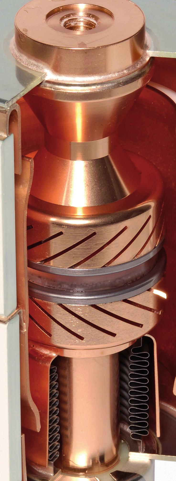
65 R-HG tif
SION Vacuum Circuit-Breakers. Answers for energy. Medium-Voltage Equipment Selection and Ordering Data. Catalog HG
 Medium-Voltage Equipment Selection and Ordering Data Catalog HG 11.0 008 Answers for energy. R-HG11-17.tif Siemens HG 11.0 008 Contents Contents Page SION Vacuum Circuit-Breakers Description General Construction
Siemens AG Catalog HG11.07 Edition 10/ AE6 Medium-Voltage Equipment. siemens.com/sion
 Siemens AG 2018 Catalog HG11.07 Edition 10/ 2018 SION Lateral Vacuum Circuit-B Breaker with Laterrall Operating Mechaniism m 3AE6 Medium-Voltage Equipment siemens.com/sion 2 Catalog HG11.07 10 / 2018 SION
3TM Vacuum Contactors
 Catalog Extract HG 11.23 Edition 2016 Catalog Extract Medium-Voltage Equipment siemens.com/3tm R-HG11-343.psd 2 Siemens HG 11.23 2016 Contents Medium-Voltage Equipment Catalog Extract HG 11.23 2016 Contents
Vacuum Circuit-Breaker Modules
 Vacuum s Medium-Voltage Equipment Catalog HG.5 998 Vacuum s Medium-Voltage Equipment Description Catalog HG.5 998 Siemens AG 998 NXACT Vacuum vacuum circuit-breaker module, kv Features DIN EN ISO 900
Fixed-Mounted Circuit-Breaker Switchgear Type 8DA and 8DB up to 40.5 kv, Gas-Insulated
 www.siemens.com/medium-voltage-switchgear Fixed-Mounted Circuit-Breaker Switchgear Type 8D and 8DB up to 0.5 kv, Gas-Insulated Medium-Voltage Switchgear Catalog H 35.11 201 nswers for infrastructure and
Catalog HA Edition up to 24 kv, Air-Insulated, Extendable. Medium-Voltage Switchgear. siemens.com/simosec
 Catalog HA 41.43 Edition 2018 Switchgear Type SIMOSEC, up to 24 kv, Air-Insulated, Extendable Medium-Voltage Switchgear siemens.com/simosec Application Typical uses R-HA41-135.tif R-HA40-112.tif R-HA41-115.tif
Outdoor live tank vacuum circuit breaker Type OVB-VBF for 24/36/40.5 kv applications
 Outdoor live tank vacuum circuit breaker Type OVB-VBF for 24/36/40.5 kv applications ABB a global leader ABB is a global leader in power and automation technologies that enable utility and industry customers
Switchgear Type SIMOSEC, up to 24 kv, Air-Insulated, Extendable
 www.siemens.com/medium-voltage-switchgear Switchgear Type SIMOSEC, up to 24 kv, Air-Insulated, Extendable Medium-Voltage Switchgear Catalog HA 41.43 2012 Answers for infrastructure and cities. Neue Bilder
Contactor-Fuse Combination 3TL62 / 63 / 66
 Contactor-Fuse Combination TL6 / 6 / 66 Medium-Voltage Equipment Selection and Ordering Data Catalog HG. 00 Answer for energy. Contactor-Fuse Combination TL6 / 6 / 66 R-HG-.tif Siemens HG. 00 Contactor-Fuse
Fixed-Mounted Circuit-Breaker Switchgear Type NXPLUS C up to 24 kv, SF 6 -Insulated. Medium-Voltage Switchgear Catalog HA 35.
 Fixed-Mounted Circuit-Breaker Switchgear Type NXPLUS C up to kv, SF 6 -Insulated Medium-Voltage Switchgear Catalog HA 5. 00 Invalid: Catalog HA 5. 00 R-HA5-05 eps Fixed-Mounted Circuit-Breaker Switchgear
HB3-80 Generator Circuit-Breaker Switchgear. Medium-Voltage Switchgear. Totally Integrated Power HB3-80. Catalog HB3-80.
 HB3-80 Generator Circuit-Breaker Switchgear Medium-Voltage Switchgear Totally Integrated Power HB3-80 Catalog HB3-80 Edition 2014 www.siemens.com/generatorswitchgear R-HB1-001.tif R-HB3-001.tif R-HB3-003.tif
HB3 Generator Circuit-Breaker Switchgear
 Catalog HB3 Edition 2017 HB3 Generator Circuit-Breaker Switchgear Medium-Voltage Switchgear siemens.com/generatorswitchgear R-HB1-001.tif R-HB3 001.tif R-HB3 003.tif R-HB3 002.jpg 2 HB3 Generator Circuit-Breaker
Switchgear Type 8DJH for Secondary Distribution Systems up to 24 kv, Gas-Insulated
 Switchgear Type 8DJH for Secondary Distribution Systems up to 24 kv, Gas-Insulated Medium-Voltage Switchgear Catalog HA 40.2 2009 Answers for energy. -HA40-111.eps -HA40-110.eps -HA40-109.eps -HA40-112.eps
Switchgear Type 8DJH 36 for Secondary
 Catalog HA 40.3 Edition 2017 Switchgear Type 8DJH 36 for Secondary Distribution Systems up to 36 kv, Gas-Insulated Medium-Voltage Switchgear siemens.com/8djh36 Application Typical uses R-HA40-135.tif R_HA40-150a
Fixed-Mounted Circuit-Breaker Switchgear Type NXPLUS up to 40.5 kv, Gas-Insulated
 www.siemens.com/medium-voltage-switchgear Fixed-Mounted Circuit-Breaker Switchgear Type NXPLUS up to 40.5 kv, Gas-Insulated Medium-Voltage Switchgear Catalog HA 35.5 203 Answers f infrastructure and cities.
Switchgear Type SIMOSEC, up to 24 kv, Air-Insulated, Extendable
 Switchgear Type SIMOSEC, up to 24 kv, Air-Insulated, Extendable Medium-Voltage Switchgear Totally Integrated Power SIMOSEC Catalog HA 41.43 Edition Sept. 2014 Answers for infrastructure and cities. Neue
Fixed-Mounted Circuit-Breaker Switchgear Type 8DA and 8DB up to 40.5 kv, Gas-Insulated
 Fixed-Mounted Circuit-Breaker Switchgear Type 8D and 8DB up to 0.5 kv, Gas-Insulated Medium-Voltage Switchgear Catalog H 35. 00 nswers for energy. R-H35-30.eps pplication Public power supply system R-H35-3.eps
Switchgear Type 8DJH for Secondary Distribution Systems up to 24 kv, Gas-Insulated
 Switchgear Type 8DJH for Secondary Distribution Systems up to 24 kv, Gas-Insulated Medium-Voltage Switchgear Catalog HA 40.2 2010 Answers for energy. -HA40-110.eps -HA40-109.eps -HA40-112.eps -HA40-111.eps
Switchgear Type 8DJH for Secondary Distribution Systems up to 24 kv, Gas-Insulated
 Catalog HA 40.2 Edition 2017 Switchgear Type 8DJH for Secondary Distribution Systems up to 24 kv, Gas-Insulated Medium-Voltage Switchgear siemens.com/8djh Application Typical uses R-HA40-111.tif R-HA40-112.tif
Switchgear Type 8BT1, up to 24 kv, air-insulated. Medium Voltage Switchgear Catalog HA 26.
 www.siemens.com/medium-voltage-switchgear Switchgear Type 8BT1, up to 24 kv, air-insulated Medium Voltage Switchgear Catalog HA 26.31 2012 Answers for infrastructure and cities. R-HA26-013. eps Contents
High-Voltage Circuit-Breakers 3AP1/ kv up to 550 kv. Power Transmission and Distribution
 High-Voltage Circuit-Breakers AP/ 7.5 kv up to 550 kv Power Transmission and Distribution The AP/ High-Voltage Circuit-Breakers Now Applicable for 550 kv Decades of our experience in high-voltage switching
SION OPERATING INSTRUCTIONS. Vacuum circuit-breakers kv, ka kv, 40 ka 24 kv, ka
 SION Vacuum circuit-breakers 7.2 17.5 kv, 12.5 31.5 ka 7.2 17.5 kv, 40 ka 24 kv, 12.5 25 ka OPERATING INSTRUCTIONS Order no.: 9229 0001 176 0G Ordering location: EM LP IEC PRM MVP AG 09.2015 en Siemens
3AK OPERATING INSTRUCTIONS. Vacuum circuit-breaker module 3AK1 and 3AK3
 3AK Vacuum circuit-breaker module 3AK1 and 3AK3 OPERATING INSTRUCTIONS Order no.: 9229 9923 176 0B Ordering location: IC LMV LP PO P C41 AG 09.2013 en Siemens AG 2006. All rights reserved. For your safety
MEDIUM VOLTAGE PRODUCTS. Powerbloc Pre-assembled modules for building medium voltage switchgear
 MEDIUM VOLTAGE PRODUCTS Powerbloc Pre-assembled modules for building medium voltage switchgear Powerbloc are the ideal solution for replacing fixed circuit breakers with withdrawable circuit breakers,
B kv T&D GAS INSULATED SWITCHGEAR
 GAS INSULATED SWITCHGEAR B 105 170 300 kv The increasing demand for electrical power in cities and industrial centers necessitates the installation of a compact and efficient distribution and transmission
NXPLUS C Single busbar. Maintenance-free for lifetime
 NXPLUS C Single busbar Maintenance-free for lifetime Energy Distribution Welcome! Page 2 Content Overview Technical data Typicals Panel design Circuit-Breaker panel Busbar Operation Metering Low-voltage
Benefits, typical uses
 R-HA26-013. eps Switchgear Type 8BT1, up to 24kV,Air-Insulated Contents Application Page Application Benefits 2 Typical uses 2 and 3 Technical Data Ratings 4 Classification, dimensions, 5 room planning
DISTRIBUTION SOLUTIONS. GSec Gas-insulated switching and isolating apparatus
 DISTRIBUTION SOLUTIONS GSec Gas-insulated switching and isolating apparatus GSec is a three-position SF6 gas-insulated switchdisconnector designed for use in medium voltage switchgear for secondary distribution
Type SIMOPRIME A4, up to 24 kv, Air-Insulated Medium-Voltage Switchgear
 Circuit-Breaker www.siemens.com/energy Switchgear Type SIMOPRIME A4, up to 24 kv, Air-Insulated Medium-Voltage Switchgear s Technology Circuit-Breaker Switchgear Type SIMOPRIME, up to 17.5 kv, Air-Insulated
Vacuum Circuit-Breakers, Type HVX kv, of cassette design, cassette with motor drive
 Vacuum Circuit-Breakers, Type HVX 12 24 kv, of cassette design, cassette with motor drive Operating Instructions No. 531 321, Edition 09/00 Table of Contents 1 General 4 1.1 Operating Conditions 4 2 Design,
HVX Series. 36 kv Medium Voltage Vacuum circuit breaker. Make the most of your energy SM. Medium Voltage Distribution Catalogue 2015
 Medium Voltage Distribution Catalogue 205 HVX Series 36 kv Medium Voltage Vacuum circuit breaker Fixed, middle rolling and floor rolling ranges of circuit breaker and disconnector Make the most of your
1. Safety practices General Introduction Standards...3
 1. Safety practices...2 2. General...3 2.1 Introduction...3 2.2 Standards...3 3. Technical data...3 3.1 Designation...3 3.2 Electrical ratings and dimensions...4 3.3 Fixation...6 3.4 Connecting terminals...6
GMA. Medium-voltage switchgear
 Medium-voltage switchgear Gas-insulated switchgear up to 24 kv - 2500 A - 31.5 ka Earthing without automatically CLOSE / OPEN of the Circuit Breaker Operation - Maintenance Technical Manual No. AGS 531
VD4/R. Medium Voltage vacuum circuit-breakers for secondary distribution
 VD4/R Medium Voltage vacuum circuit-breakers for secondary distribution DESCRIPTION CIRCUIT-BREAKER SELECTION AND ORDERING SPECIFIC PRODUCT CHARACTERISTICS OVERALL DIMENSIONS ELECTRIC CIRCUIT DIAGRAM
GE Consumer & Industrial Power Protection. New. SecoGear kV Metal-clad Switchgear. GE imagination at work
 GE Consumer & Industrial Power Protection New SecoGear 12-24kV GE imagination at work General SecoGear metal-clad switchgear is designed and manufactured with advance technology and has been comprehensively
B kv Gas-insulated Substations
 72.5 145 kv Gas-insulated Substations The increasing demand for electrical power in cities and industrial centres requires the installation of a compact and efficient distribution and transmission network.
HD4. Gas insulated MV circuit-breakers kv A ka
 HD4 Gas insulated MV circuit-breakers 12... 40.5 kv - 630... 3600 A - 16... 50 ka 1 DESCRIPTION Autopuffer breaking technique Electric arc extinction without chopped current No restriking after breaking
Circuit-Breaker Switchgear Type SIMOPRIME, up to 17.5 kv, Air-Insulated Medium-Voltage Switchgear.
 Circuit-Breaker Switchgear Type SIMOPRIME, up to 17.5 kv, Air-Insulated Medium-Voltage Switchgear www.siemens.com/energy Technology s Contents Application Page Benefits 2 Typical uses 2 and 3 Technical
Outdoor live tank SF 6. circuit breaker Type OHB for 24/36/40.5 kv applications
 Outdoor live tank SF 6 circuit breaker Type OHB for 24/36/40.5 kv applications ABB a global leader ABB is a global leader in Power and Automation technologies that enable utility and industry customers
Vacuum Circuit-Breaker 3AH1 7.2kV to 24kV 3AH1
 Vacuum Circuit-Breaker 72kV to 24kV 72kV 24 kv Operating Instruction/ Order-No:/ : 3ZX1812-0AH10-0AN2/9229 9656 174-SLC PTD MC R-HG11-074a eps All right reserved / Siemens AG 1996 & SLC PTD MC 2001 Operating
VCP-T/T-VAC medium voltage vacuum circuit breakers. Control and protect with Eaton s compact medium voltage circuit breakers
 VCP-T/T-VAC medium voltage vacuum circuit breakers Control protect with Eaton s compact medium voltage circuit breakers Eaton Corporation has dedicated years of research, design testing to create a comprehensive
Specification for 70mm pole pitch Air circuit breaker up to 1600 A
 Specification for 70mm pole pitch Air circuit breaker up to 1600 A Protective device for low voltage electrical installation Last update :2011-07-08-1 - Table of contents: 1 General...3 2 Compliance with
Rated voltage 12 kv to 38.5 kv Rated current 630 A to 2500 A
 KUF DRIESCHER Indoor Vacuum CircuitBreaker voltage to.5 kv current to 00 A 4kV 746 Get connected http://www.driescher.com V6 ELEKTROTECHNISCHE WERKE FRITZ DRIESCHER & SÖHNE GMBH D8566 MOOSBURG TEL. +49
SION vacuum circuit-breaker.
 A perfect fit for every substation: vacuum circuit-breaker. The new line in medium voltage. Power Transmission and Distribution Every innovation begins with an idea. Form, functionality and flexibility
AIR INSULATED EXTENDABLE SWITCHGEAR UP TO 12KV GUIDE
 AIR INSULATED EXTENDABLE SWITCHGEAR UP TO 12KV GUIDE Certificate Number FM35831 APPLICATION Typical Uses and Classification The MSGair switchgear is used in transformer and switching substations mainly
Vacuum Circuit Breaker VS1
 Vacuum Circuit Breaker VS1 Product features Conform to GB, IEC, DL and JB standards KEMA type test Level A certificate Ideal contact material and shape, ensuring low current carrying value and stable contact
GE Electrical Distribution. Gerapid High Speed DC Circuit Breakers. On the move. imagination at work
 GE Electrical Distribution Gerapid High Speed DC Circuit Breakers On the move imagination at work Gerapid High Speed DC Circuit Breakers To stay up and running today, you need equipment that delivers both
Outdoor vacuum breaker for railway applications - FSK II
 Outdoor vacuum breaker for railway applications - FSK II Single or two-pole outdoor vacuum breaker with magnetic actuator 27.5 kv - 250 kv BIL - 1250 A. 2000 A - 25.0 ka - 50/60 Hz 27.5 kv - 200 kv BIL
The vacuum circuit breaker for commercial buildings, industrial plants and utilities
 The vacuum circuit breaker for commercial buildings, industrial plants and utilities EasyPact EXE The easy choice for more value 2 EasyPact EXE EasyPact EXE, a medium voltage vacuum circuit breaker optimizing
Outdoor live tank SF6 circuit breaker EDT with integrated current transformer up to 72.5 kv
 Outdoor live tank SF6 circuit breaker EDT with integrated current transformer up to 72.5 kv SF6 circuit breaker EDT with integrated current transformer ABB is a world leader in live tank circuit breaker
MV Air Insulated Switchgear TAP17. Technical Data TGOOD
 MV Air Insulated Switchgear TAP17 Technical Data TGOOD 2017.1 Operating environmental conditions Place of installation: Indoor or outdoor Ambient temperature: 25 ~ +40 (higher or lower temperature optional)
R-MAG Vacuum Circuit Breaker with Magnetic Actuator Mechanism 15.5 kv - 27 kv; 1200 A A
 R-MAG Vacuum Circuit Breaker with Magnetic Actuator Mechanism 15.5 kv - 27 kv; 1200 A - 3700 A R-MAG The R-MAG is truly the next generation in vacuum circuit breakers, combining industry recognized magnetic
Medium-Voltage Switchgear OPERATING INSTRUCTIONS
 Medium-Voltage Switchgear Circuit-Breaker Switchgear Type NXAIR: Factory-Assembled, Type-Tested and Metal- Enclosed Switchgear for Indoor Installation, Air-Insulated Loss of Service Continuity Category:
Medium voltage products UniSec DY800 New 24 kv air-insulated medium voltage switchgear to e-distribuzione specifications
 Medium voltage products UniSec Y800 New 24 kv air-insulated medium voltage switchgear to e-istribuzione specifications UniSec Y800 ubicles available Unit e-istribuzione specifications (Ed. 4) UniSec IS/1
Using new Magnetically Actuated Vacuum Interrupter technology for safe and reliable medium voltage circuit breaker switching in mines
 Using new Magnetically Actuated Vacuum Interrupter technology for safe and reliable medium voltage circuit breaker switching in mines Abstract: The development of the magnetically actuated vacuum interrupter
Retrofit for gas-insulated high voltage switchgear (GIS) - 8D1 and 8D2
 - 8D1 and 8D2") Retrofit for gas-insulated high voltage switchgear (GIS) - 8D1 and 8D2 Table of Contents 1 Introduction... 4 2 Description of retrofit circuit-breaker 8DN8... 5 3 Technical data for retrofit circuit-breaker
Retrofit for gas-insulated high voltage switchgear (GIS) - 8D1 and 8D2 Table of Contents 1 Introduction... 4 2 Description of retrofit circuit-breaker 8DN8... 5 3 Technical data for retrofit circuit-breaker
TECHNICAL SPECIFICATION OF 11KV SF6 / VCB METAL ENCLOSED, INDOOR (PANEL TYPE) / OUTDOOR RING MAIN UNIT (RMU). (IEC standard equipment)
 / OUTDOOR RING MAIN UNIT (RMU). (IEC standard equipment)") TECHNICAL SPECIFICATION OF 11KV SF6 / VCB METAL ENCLOSED, INDOOR (PANEL TYPE) / OUTDOOR RING MAIN UNIT (RMU). (IEC standard equipment) 1 SCOPE OF SUPPLY This specification covers design, manufacture, shop
TECHNICAL SPECIFICATION OF 11KV SF6 / VCB METAL ENCLOSED, INDOOR (PANEL TYPE) / OUTDOOR RING MAIN UNIT (RMU). (IEC standard equipment) 1 SCOPE OF SUPPLY This specification covers design, manufacture, shop
Metal Clad Air Insulated Switchgear
 Metal Clad Air Insulated Switchgear 1/ SecoGear Metal Clad Switchgear Features Fully metal-clad Equipped with Embedded pole VCB Full Front access (can be installed against wall) Perfect interlocking system
General. Main electric circuits Fuses compartment Operating mechanisms Cables connection compartment
 General The switchgear must be suitable for 36 kv rated voltage and specifically conceived for the secondary distribution substations in M.V. with either ring or radial type networks. The switchgear must
16kA Solid Dielectric, Triple Option Reclosers Catalog VLT12
 16kA Solid Dielectric, Triple Option Reclosers Providing electronic overcurrent protection for single or three phase operation on systems rated through 27kV, 630A continuous current, 16kA symmetrical interrupting
Medium voltage vacuum circuit breaker. E-VAC series
 Medium voltage vacuum circuit breaker E-VAC series Product description E-VAC vacuum circuit breaker Contents Description Product description... Technical data... Dimensions... Wiring diagram... E-VAC series
Air Circuit Breakers
 Siemens AG 203 /2 Introduction 3WL air circuit breakers/ non-automatic air circuit breakers up to 6300 A (AC), IEC /8 Introduction /9 3-pole, fixed-mounted versions /6 3-pole, withdrawable versions /23
PIX-H Metal-clad switchgear up to 17.5kV
 AIR INSULATED SWITCHGEAR PIX-H Metal-clad switchgear up to 17.5kV for high rated applications Technical Specifications AREVA T&D Summary - Technical description... 3 - Standards... 6 - PIX in detail...
8DJ. Maintenance-free for lifetime
 8DJ Maintenance-free for lifetime Energy Distribution Welcome! Page 2 October 1 st 2008 8DJ Main Applications for Medium-Voltage Switchgear Power generation Power stations G Power transmission High and
CPG.0 Single busbar gas-insulated cubicles
 MV Switchgear Primary Distribution CPG.0 Single busbar gas-insulated cubicles Up to 36 kv CPG System The quality of products designed, manufactured and installed by Ormazabal is underpinned by the implementation
SF 6 Gas Insulated Switchgear Type SDH314 / SDHa314 for 72.5 to 145 kv
 Three Phase Encapsulated Type SF 6 Gas Insulated Switchgear Type SDH314 / SDHa314 for 72.5 to 145 kv 06B1-E-0002 Small Space Requirement, High Reliability and Safety ー 72.5 to 145 kv GIS, SDH314/SDHa314
We build a better future!
 We build a better future! C O N T E N T S 3 4 5 6 7 15 17 17 18 20 21 39 Description Application Selection Guide Arc-quenching System Type & Rating Construction & Operation Current Carrying Capacity Standard
Vmax Medium voltage vacuum circuit-breakers. IEC: kv; A; ka ANSI: kv; A; ka
 Medium voltage products Vmax Medium voltage vacuum circuit-breakers IEC:... 17.5 kv;... 1250 A;... 31.5 ka ANSI:... 15 kv;... 1200 A;... 31.5 ka The new Vmax circuit-breakers are the synthesis of ABB s
Ensuring excellent switching capability and high quality with various advantages
 VCB Vacuum Circuit Breaker Ensuring excellent switching capability and high quality with various advantages Retaining the high dielectric strength with the interrupter of the high vacuum degree of 10-7
Power systems Protection course
 Al-Balqa Applied University Power systems Protection course Department of Electrical Energy Engineering Dr.Audih 1 Part 3 Protective Devices Fuses & Circuit Breakers 2 Introduction: Fuse Is advice used
Air Circuit Breakers
 Siemens AG 204 /2 Introduction 3WL air circuit breakers/ non-automatic air circuit breakers up to 6300 A (AC), IEC /8 Introduction /9 3-pole, fixed-mounted versions /6 3-pole, withdrawable versions /23
Gas-insulated medium-voltage switchgear. For the mining industry. Answers for energy.
 Gas-insulated medium-voltage switchgear For the mining industry Answers for energy. Full power even under extreme conditions Reliable All over the world, the demand for mineral resources is increasing.
KYN28A-12 (GZS1) A.C METALCLAD REMOVABLE SWITCHGEAR FOR INDOOR USE CHINATCS
 A.C METALCLAD REMOVABLE SWITCHGEAR FOR INDOOR USE CHINATCS") KYN28A-12 (GZS1) A.C METALCLAD REMOVABLE SWITCHGEAR FOR INDOOR USE CHINATCS 2001.09 KYN28A-12 (GZS1) A.C Metalclad Removable Switchgear for Indoor Use --------The Leader in Switchgear Up to 12kV 1. The
KYN28A-12 (GZS1) A.C METALCLAD REMOVABLE SWITCHGEAR FOR INDOOR USE CHINATCS 2001.09 KYN28A-12 (GZS1) A.C Metalclad Removable Switchgear for Indoor Use --------The Leader in Switchgear Up to 12kV 1. The
R-MAG. Vacuum Circuit Breaker with Magnetic Actuator Mechanism
 R-MAG Vacuum Circuit Breaker with Magnetic Actuator Mechanism R-MAG Features: Low maintenance 10,000 mechanical operations (five times ANSI requirements) Simple magnetic actuator Vacuum interruption Definite
CPG.1 Gas insulated, single busbar cubicle range Up to 27 kv / 2000 A / 31.5 ka Up to 38 kv / 2000 A / 31.5 ka IEEE Standards
 Medium Voltage Switchgear Primary Distribution CPG.1 Gas insulated, single busbar cubicle range Up to 27 kv / 2000 A / 31.5 ka General description Presentation Ormazabal s CPG System includes the CPG.1
3 - Protection components Motor circuit-breakers
 Contents 0 - Protection components Motor circuit-breakers protection components for the motor protection Thermal-magnetic motor circuit-breakers Selection guide..............................................page
HIGS Highly Integrated Generator Circuit-Breaker Switchgear
 Catalog HIGS Edition 2018 HIGS Highly Integrated Generator Circuit-Breaker Switchgear Medium-Voltage Switchgear siemens.com/generatorswitchgear HIGS_2 tif HIGS_1 jpg HIGS_3 tif Application: Gas-fired steam
Air-insulated switchgear UniGear type ZS1
 Air-insulated switchgear UniGear type ZS1 ABB Power Technologies / 1-7074 D 12-03-2003 - Air-insulated switchgear UniGear type ZS1 ABB Power Technologies / 2-7075 D 1 2-03-2003 - Rated voltage kv 12 17.5
Types. Fixed-mounted circuitbreaker. NXPLUS C is a factoryassembled,
 R-HA5-05a eps Fixed-Mounted Circuit-Breaker Switchgear Type NXPLUS C, up to kv, Gas-Insulated Contents Application Page Types Application Types, typical uses, ratings to Requirements Features, safety,
Solid Dielectric, Triple Option Reclosers Catalog O-vlt14
 Solid Dielectric, Triple Option Reclosers Providing electronic overcurrent protection for single or three phase operation on systems rated through 27kV, 630A or 800A continuous current, 12.5 or 16kA symmetrical
Medium-Voltage Switchgear
 Medium-Voltage Switchgear Type SIMOSEC 12 up to 12 kv, Extendable, up to 1250 A Medium-Voltage Switchgear INSTALLATION AND OPERATING INSTRUCTIONS Order No.: 834-6001.9 Revision: 01 Issue: 21-09-2009 About
HD4. Gas insulated MV circuit-breakers kv A ka
 HD4 Gas insulated MV circuit-breakers 12... 40.5 kv - 630... 3600 A - 16... 50 ka DESCRIPTION CIRCUIT-BREAKER SELECTION AND ORDERING CBE ENCLOSURE SELECTION AND ORDERING CBF FIXED PART SELECTION AND ORDERING
Solid Dielectric, Triple Option Reclosers Catalog O-vlt14
 Solid Dielectric, Triple Option Reclosers Providing electronic overcurrent protection for single or three phase operation on systems rated through 27kV, 630A or 800A continuous current, 12.5 or 16kA symmetrical
Voltage Rated operating voltage [kv] Rated power frequency withstand voltage [kv] Rated lightning impulse withstand voltage [kv]
![Voltage Rated operating voltage [kv] Rated power frequency withstand voltage [kv] Rated lightning impulse withstand voltage [kv]](/thumbs/80/82203973.jpg "Voltage Rated operating voltage [kv] Rated power frequency withstand voltage [kv] Rated lightning impulse withstand voltage [kv]") BasisBlock MC 1 Standards and Regulations IEC 62271-200 ; VDE 0671-200 ; BS EN 62271-200 Technical Data MC1-12 MC1-24 Voltage Rated operating voltage [kv] 12 24 Rated power frequency withstand voltage
BasisBlock MC 1 Standards and Regulations IEC 62271-200 ; VDE 0671-200 ; BS EN 62271-200 Technical Data MC1-12 MC1-24 Voltage Rated operating voltage [kv] 12 24 Rated power frequency withstand voltage
Air Insulated Switchgear NXAirS, 40.5kV Answers for infrastructure and cities.
 www.siemens.com.cn/medium-voltage-switchgear Air Insulated Switchgear NXAirS, Answers for infrastructure and cities. Applications Page Application Type 2 Typical uses 3 Classification 3 Type NXAirS withdrawable
Indoor switches for railway lines. single-pole design rated voltage up to 27,5 kv rated current up to 4000 A
 Indoor switches for railway lines single-pole design rated voltage up to 27,5 kv rated current up to 4000 A General These Driescher indoor switching devices are specifically designed for railway applications.
W-VACi IEC medium voltage vacuum circuit breakers 12 kv, 17,5 kv and 24 kv
 This is a photographic template your photograph should fit precisely within this rectangle. W-VACi IEC medium voltage vacuum circuit breakers 12 kv, 17,5 kv and 24 kv Mostapha Azzahimi Product Manager
Contactor V-Contact VSC/P
 Argentina Buenos Aires November 30, 2006 Contactor V-Contact VSC/P 1VCP000XXX Rev.B, en Presentation - 2006.XX. V-Contact VSC Contactors QUALITY SYSTEM : Certification ISO 9001-2000 ENVIRONMENTAL MANAGEMENT
Medium Voltage Metal-Enclosed Switches
 Medium Voltage Metal-Enclosed Switches Outdoor Medium Voltage Switch.1 Medium Voltage Switch MVS Product Description............................................. 2 Application Description..........................................
The 3AH Vacuum Circuit-Breakers Versatile, High-Performing, Economical
 The 3AH Vacuum Circuit-Breakers Versatile, High-Performing, Economical Five Circuit-Breakers any Task Nowadays circuit-breakers are used for the most varied of tasks - they switch all kinds of devices,
Type SDV6 distribution circuit breaker. Top performance - proven reliability. Answers for energy.
 Type SDV6 distribution circuit breaker Top performance - proven reliability Answers for energy. Table of contents Introduction 2-4 Type 3AH3 stored-energy operating mechanism 6 Vacuum interrupters 7 Ratings
DMX 3 -I 2500 switch disconnectors
 8704 LIMOGES Cedex Telephone : 0 0 87 87 Fax : 0 0 88 88 DMX 3 200 circuit breakers DMX 3 -I 200 switch disconnectors References: 0 28 20 / 21 / 22 / 23 / 24 / 2 / 2 / 30 / 31/ 32/ 33/ 34 / 3 / 3 / 40
Horizontal Circuit Switchers
 > Transformer Protection > CIRCUIT SWITCHERS C A T A L O G B U L L E T I N General Application Southern States Types CSH and CSH-B Horizontal Circuit Switchers provide an economical, versatile, space saving
Dead Tank Circuit Breaker 145PM40-C Compact design with enhanced reliability
 Dead Tank Circuit Breaker 145PM40-C Compact design with enhanced reliability ABB innovations for changing demands ABB (www.abb.com) is a leader in power and automation technologies that enables utility
Power IT MV Live Tank Vacuum Circuit Breaker Model VBF
 Power IT MV Live Tank Vacuum Circuit Breaker Model VBF ABB - a global leader in power and automation technologies ABB (www.abb.com) is a global leader in power and automation technologies that enable utility
Switchgear Type 8DH10 up to 24 kv, Gas-Insulated, Extendable
 Switchgear Type DH0 up to kv, Gas-Insulated, Extendable Medium-Voltage Switchgear Catalog HA. 00 Answers for energy. Contents Application, Requirements Features Application, Requirements Page Features,
SWITCHGEAR FOR SERVICE UP TO 36kV (CABLE AND OVERHEAD CONDUCTOR CONNECTED)
") PRODUCED BY THE OPERATIONS DIRECTORATE OF ENERGY NETWORKS ASSOCIATION Issue 3 2012 SWITCHGEAR FOR SERVICE UP TO 36kV (CABLE AND OVERHEAD CONDUCTOR CONNECTED) www.energynetworks.org 2012 Energy Networks
PRODUCED BY THE OPERATIONS DIRECTORATE OF ENERGY NETWORKS ASSOCIATION Issue 3 2012 SWITCHGEAR FOR SERVICE UP TO 36kV (CABLE AND OVERHEAD CONDUCTOR CONNECTED) www.energynetworks.org 2012 Energy Networks
3.1. Power Breakers, Contactors and Fuses. Contents. Series NRX Low Voltage Power Circuit Breakers. Power Circuit Breakers
 .1 Series NRX Low Voltage Series NRX Low Voltage Product Description Series NRX is a low voltage power circuit breaker suitable for UL 1558, UL 891, and IEC switchgear and switchboards. The compact size
FUSES. Safety through quality
 Safety through quality HH HIGH VOLTAGE Over many decades SIBA has developed a global product line of High Voltage Fuses that are comprehensive for any and all applications. Superior engineering, advanced
Solid Dielectric, Single Phase Recloser
 Solid Dielectric, Single Phase Recloser Catalog O-vsp17 Viper-SP Viper-SP solid dielectric, single phase recloser combines the time-proven reliability of electronically controlled, vacuum fault interrupters