Service and Repair Manual
|
|
|
- Jasper Mosley
- 6 years ago
- Views:
Transcription


1 Transaxle Type RS800P Service and Repair Manual A November 2015
2 Table of content -Table of content... -Introduction -External Controls and functions.. -Product identification.... -Safety.... -Preliminary check before tearing down the transmission. -Preliminary check before re-install the transmission... -Troubleshooting.. -Transmission tear down.... -Repair procedures. -Exploded views.... -Notes to to Introduction I- General Transmissions presentation With 3 production sites, Mexico, China, France, and a policy focus on product quality and continuous innovation, General Transmission became a world leader in the design and manufacture of gearbox and transaxle, for lawn and garden equipment. II- Manual introduction The purpose of this manual is to provide service and repair information for the RS800P transaxle. Also included are exploded view, troubleshooting and repair procedures. III- RS800P transaxle general description The RS800P transaxle is design to provide an infinitely variable speed range and reverse operation thru a single pedal control. This transaxle also offer an integrate differential function and neutral automatic braking. IV- How to use this manual General Transmissions recommend, before tearing down the RS800P transaxle, to make sure that you have a clean and organize work area, as well as the required specific tools. General Transmissions also recommend to carefully read the general instructions provided in the manual (p.5), before starting any reparation. After detected the potential defective component, using the troubleshooting, follow the repair procedures. It is necessary to complete the Preliminary operation, to be able to make the Replacement operation (see troubleshooting p.7). A defective component might cause premature wear or deterioration of other components. Make sure that all necessary kit have been replaced. For all service or repair operation, respect the shop and government safety rules. 2


3 External Controls and Functions Main pulley Output shaft Output shaft Inversion/Variation control Bypass lever Brake lever Switch 3


4 Product identification -The product identification number is located on the top of the barre-code sticker and engraved on the left output shaft. Safety Personal Safety Safety precautions must be observed while servicing or repairing the transmission. This section is to be used in conjunction with all other safety material which may apply, such as: -Local and shop safety rules. -Government safety laws and regulations. Tool Safety Use the proper tools and equipment for the task. Servicing Safety Certain procedures may require the vehicle to be disabled. Do not place speed above safety. Wear appropriate clothing. Loose or hanging clothing can be hazardous. Use the appropriate safety equipment. 4
 - Check")

 Preliminary check before re-install the transmission - Ensure that the variation")
5 General Instructions Preliminary check before tearing down the transmission - Clean up the transmission - Check all the control between tractor and transmission (see owner manual) - Check the belt routing - In case of failure in cold condition, check the transmission functionality after a while in a dry place. Failure might come from a frozen controls system. - Check the correct installation of the transmission (see view below) Screwing torque: 13 ±3 Nm (9.5 ±2 lb-ft) Preliminary check before re-install the transmission - Ensure that the variation belt is in good position. 5


6 - Make sure that the inversion rod is properly seated in the inversion lever, and have its 2 springs. Inversion lever Springs - Verify the presence of the 4 springs. - Ensure that both variation levers are in correct position. 6
7 Troubleshooting Customer complaints loss of traction loss of inversion function trouble to inverse loss of automatic brake (neutral position) loss of brake function Troubleshooting checklist p. 9 p. 10 p. 11 p. 11 p. 12 p. 13 p. 14 p.17 p.18 Potential failure Item to OP1 OP2 OP3 OP4 OP5 OP6 OP7 OP8 OP9 PN replace Driver Driven ISSS Cover Variation Brake Control Bypass Inversion broken driver shaft Driver Kit GT79260 R broken control cam P P P R broken guidance rod Control Kit GT79256 P P P R broken control rods axle P P P R broken variation P R lever Variation Kit GT79254 broken variation P P P R rod loss of variation clip Hardware kit GT79323 P P loss of control rods clip Hardware kit GT79323 variator belt failure Variator belt GT37401 R Internal failure Transmission broken inversion rod P P P P P R broken inversion Inversion Kit GT79258 rod spring P P P P P R broken inversion lever 2 stop plate stuck on the control cam inversion security system failure Internal failure broken brake spring broken brake axle broken aluminium brake lever Internal failure Control Kit GT79256 P P P R Clean cam and stop plate Inversion security system set Transmission Brake Kit X P P R GT79186 P R GT79255 P P R P P R Brake Kit GT79255 P P R Transmission loss of speed range broken driven variation spring driver shaft lower bearing failure Driven Kit GT79253 R Driver Kit GT79260 R trouble to return to the neutral position can't disable the bypass with the brake pedal loss of bypass function misadjustment of Adjust speed X R the speed (screw) broken neutral Variation Kit GT79254 P P R spring broken neutral position spring broken neutral position lever broken bypass spring broken brake lever broken bypass lever Control Kit bypass Kit GT79256 GT79257 P P P R P P P R P P R P P P P R P P P P R R = Replacement operation / P = Preliminary operation 7
. - Disconnect the brake spring (3). - Activate and lock the parking brake, to slacken the belt, and remove it from the main pulley (5).")
8 Transmission Tear Down - Remove cutting deck (see owner manual) - Lift up the rear of the tractor, then remove both rear wheels. - Disconnect the variation rod (1). - Disconnect the switch (4). - Disconnect the bypass rod (2). - Disconnect the brake spring (3). - Activate and lock the parking brake, to slacken the belt, and remove it from the main pulley (5). - Remove the mounting bolt, to separate the transmission from the frame. We recommend to keep 2 bolts partially unscrewed, to prevent the transmission falls. - Lower the rear of the tractor until the transmission lightly touches the ground, then remove the 2 last bolts. - Lift up the rear of the tractor to release the transmission. 8
 - In case of speed down, the adjusting screw located at the")


9 Repair Procedures OP 1. Driver kit replacement (view p.20) - In case of speed down, the adjusting screw located at the rear of the transmission allow to slightly increase the speed. - Use a T20 Torx screwdriver. - Note: Over-adjustment of this screw can lead to the tractor creeping in Neutral! If this occurs, simply back out the screw until neutral is re-established. -Remove the 4 screws as shown below to liberate the driver kit. -At reassembling the kit, make sure that: Both variation lever are properly seated. The belt is in the pulley. The adjusting screw is accessible. Screwing torque: 3.2 ±0.1 Nm (2,4 ±0.1 lb-ft) Variation levers position 9


 -Unscrew the nut using the special")
, then remove the fixed flange.")


10 Repair Procedures OP 2. Driven kit replacement (view p.21) -Remove the 3 screws to liberate the cover, press the aluminum ramp to compress the spring and liberate the pin, then remove the aluminum ramp, spring and mobile flange Screwing torque: 2.2±0.1 Nm (1.6±0.1 lb-ft) -Unscrew the nut using the special tool P/N (see p.19), then remove the fixed flange. Screwing torque: 90 ±8 Nm (65 ±5 lb-ft) Watch out for the balls located under the flange When re-installing the components: -Make sure the 8 balls are present under the flange. -Respect the torques of the nut and screws. -Make sure the belt is properly positioned in the pulley. -Ensure that the spring is between the mobile flange and the aluminum ramp. 10


11 Repair Procedures OP 3. Inversion security system replacement (view p.24) -Remove the inversion security system. Watch out for the balls located under the flange OP 4. Remove the protection cover Screwing torque: 3.2±0.1 Nm (2.4±0.1 lb-ft) 11
 -Disconnect both brake and neutral spring.")


12 Repair Procedures OP 5. Variation kit replacement (view p.22) -Disconnect both brake and neutral spring. -Remove the e-clip to liberate the spring and variation rod. Neutral spring E-clip Brake spring When re-assembling the components, make sure that: -Both variation levers are correctly seated on the upper case. -The adjusting screw is accessible. -The variation rod and neutral spring are properly positioned. Correct position Incorrect position Variation levers Adjusting screw 12


13 Repair Procedures OP 6. Brake kit replacement (view p.23) -Disconnect the brake spring, then remove the screws, to liberate the aluminum lever. Screwing torque: 3.2±0.2 Nm (2.4 ±0.1 lb-ft) -As the aluminum lever has a conical shape, it might be hard to remove. When re-installing the components: -Verify the presence of the O-ring -Gap between both lever is normal. -Respect screwing torque. 13


.")


14 Repair Procedures OP 7. Controls kit replacement (view p.25) -Remove the e-clip to liberate the neutral spring and the variation control. -Remove the M8 screw, the control cam and the inversion lever (white). -Remove the screw to liberate the 2 nd inversion lever. -Remove both control and variation rods. -Remove the 2 screws to liberate the neutral position lever and its spring. E-clip Variation control Neutral spring Control cam Variation rod Control rod Neutral position lever Inversion lever 14

15 Repair Procedures OP 7. Controls kit replacement When re-installing the components: -Verify the position of the neutral position lever. -Insert the inversion rod in the inversion lever before putting it on the upper case.. -Insert both control and variation rods on the upper case. Variation rod Control rod Neutral position lever Screwing torque 3.2±0.2 Nm (2.4 ±0.1 lb-ft) Inversion rod Inversion lever -The cam and the inversion lever must be install at the same time. -This assembly must be positioned at the same time on the cam pivot, inversion lever pivot and rods (5 points at the same time). -Verify the position of the variation control and its spring. 15

 - Respect the tightening torque.")

16 Repair Procedures OP 7. Controls kit replacement -The neutral position lever must be maintained to properly positioned the cam. Stopping plate Screwing torque: 6±1Nm (4.4 ±.1 lb-ft) - Respect the tightening torque. -As the variation control has not been attached, the cam should rotate freely. -The stopping plate must be free in rotation on the control cam. -Verify the position of the variation control and its spring. Correct position Incorrect position 16

 -Separate")


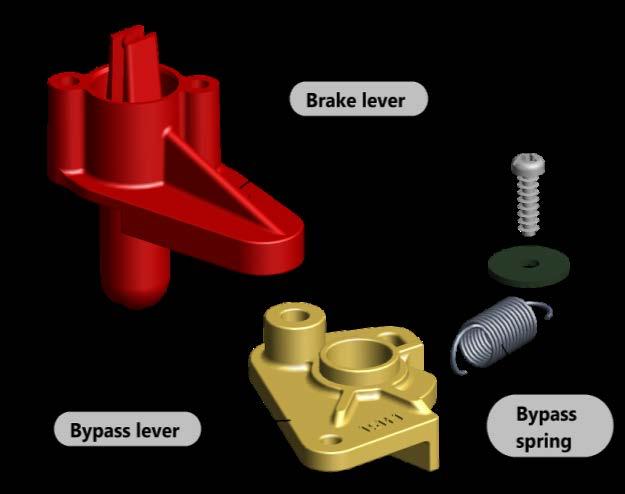
17 Repair Procedures OP 8. Bypass kit replacement (view p.26) -Separate and hold the 2 strips of the lever, to release the two studs and allow the lever removing. - Remove bypass lever and its spring. - Correct position of the bypass lever and spring. 17

 - The inversion kit is")


18 Repair Procedures OP 9. Inversion kit replacement (View p.27) - The inversion kit is located in front of the transmission. Screwing torque: 3.2±0.2 Nm (2.4 ±0.1 lb-ft) -Remove the inversion lever - Remove the nut to release the springs and rod. - When re-install the kit, respect the adjustment. 18


19 Exploded View GT79253 GT37401 GT79260 GT79186 GT38800 GT38012 GT79256 GT79254 GT79255 GT79260 GT79257 GT Item GT P/N Designation 1 GT79260 Driver kit 2 GT37401 Belt 3 GT79253 Driven kit 4 GT79186 Inversion Security System 5 GT38800 Cover 6 GT79256 Control kit 7 GT38012 Rotating cam 8 GT79254 Variation kit 9 GT79255 Brake kit 10 GT79257 Bypass kit 11 GT41821 Seals 12 GT79258 Inversion kit 13 GT79363 Hardware kit 14 GT79252 Driven tool GT Special tool is necessary to remove the driven kit GT Refer to the troubleshooting page 7, to know when driven kit must be removed.


20 Exploded Driver Kit GT79260 Driver shaft Lower bearing Speed adjustment screw 20


21 Exploded Driven Kit GT


22 Exploded Variation Kit GT79254 Adjusting screw 22


23 Exploded Brake Kit GT


24 Exploded Inversion security set GT


25 Exploded Controls Kit GT79256 Rotating cam GT


26 Exploded Bypass Kit GT


27 Exploded Inversion Kit GT


28 Hardware kit GT bypass spring 1 Neutral position spring 1 neutral spring 1 brake spring 2 washers P/N: e-clips P/N: screws 4x16 P/N: screws 5x16 P/N: screws 4x16 P/N:42623 Cover GT
29 Notes 29
30 General Transmissions BP 317 ZI du Bois Joly Sud 2, Rue Johannes Gutemberg Les Herbiers Cedex France General Transmissions China General Transmissions (Suzhou) 82 Ping Sheng Lu, SIP Suzhou, P.R.China General Transmissions inc Spectrum Way Oak Ridge North, TX USA General Transmissions de Mexico Ave. Uniones 90 - Zona Industrial Matamoros, Tam. CP Mexico After Sales Service contact service@generaltransmissions.com Ph: (281)
Transaxle Type RT400 Service and Repair Manual
 Transaxle Type RT400 Service and Repair Manual Transmission P/N MIA12863 (87095-A) 39011.B Sept. 2014 Table of content - Table of content 2 - Introduction. 2 -External Controls and Functions. 3 -Product
Transmission MV702. Product Installation & Troubleshooting
 Transmission MV702 Product Installation & Troubleshooting 39036A 2018 I Remove transmission Product installation MV702 1) Remove mower wheels, plastic covers and axle gears from both sides 2) Remove belt
XL HYDROSTATIC TRANSAXLES
 Purging Procedures Due the effects air has on efficiency in hydrostatic drive applications, it is critical that it be purged from the system. These purge procedures should be implemented any time a hydrostatic
WHEEL HORSE LAWN TRACTOR
 FORM NO. 897 WHEEL HORSE LAWN TRACTOR FOR AND 8 MOWERS SET-UP INSTRUCTIONS Loose Parts Note: Use the chart below to verify all parts have been shipped. DESCRIPTION QTY. USE Front Wheel Shim Washer (as
PIERBURG. Carburetor: 2E3
 PIERBURG Carburetor: 2E3 1 fast idle adjusting screw 2 throttle lever 3 fuel mixture adjusting screw 4 main body 5 idle cut off valve 6 stop screw 7 accelerator pump cover 8 diaphragm 9 spring 10 valve
SST Transaxle Service and Repair Manual
 SST Transaxle Service and Repair Manual BLN-0034 January, 2018 TABLE OF CONTENTS Foreword........1 Description and Operation.......2 Introduction........2 General Description... 2 Hydraulic Schematic....
TUFF TORQ TRANSAXLE. Tuff Torq Hydrostatic Transaxle. Transaxle Removal Tuff Torq
 Tuff Torq Hydrostatic Transaxle Internal Service 3. Disconnect the cotter pin and the washer to the brake rod (Figure 63). Internal service information is contained in the Tuff Torq KGIA Transaxle Service
WHEEL HORSE LAWN TRACTOR
 FORM NO. 7 0 Rev. A WHEEL HORSE LAWN TRACTOR MODEL NO. 76 590000 & UP SET-UP INSTRUCTIONS Loose Parts Use the chart below to verify all parts have been shipped. DESCRIPTION QTY. USE Front Wheel Flat Washer
Series 1000 and Cutout
 17.15.Remove the belt from the tractor. NOTE: There were a small number of tractors made using a CVT drive and a 2-speed (L-H-N-R) GT transaxle. The belt must pass over the center mounted gear selector
Symptom Possible Cause Corrective Action. * Make sure brake isn t stuck in on position. Remove brake parts as necessary to test.
 Troubleshooting Chart for the Hydro-Gear Transaxle Symptom Possible Cause Corrective Action Operates in one direction Inspect control linkage Inspect drive belt and pulleys Unit is Noisy Check oil level
MS2200, MS2500, and MS3000 Suspension Installation Manual ON/OFF HIGHWAY SUSPENSION SYSTEM
 MS22, MS25, and MS3 Suspension Installation Manual ON/OFF HIGHWAY SUSPENSION SYSTEM 972.547.62 8.445.736 FAX: 972.542.97 725 E. UNIVERSITY ST. McKINNEY, TEXAS 7569 www.watsonsuspensions.com Watson & Chalin
MODEL: 112 Lawn & Garden Tractor SIN 250,001 & Up
 John Deere MODEL: 112 Lawn & Garden Tractor SIN 250,001 & Up THIS IS A MANUAL PRODUCED BY JENSALES INC. WITHOUT THE AUTHORIZATION OF JOHN DEERE OR IT'S SUCCESSORS. JOHN DEERE AND IT'S SUCCESSORS ARE NOT
TORQUE SPECIFICATIONS (ALPHABETICAL ORDER)
") POWER TRIN HYDROSTTI SPEIFITIONS SPEIFITIONS Transaxle: Type..............................................Tuff Torq K51 Transaxle xle Torque Output: Rated...............................................
POWER TRIN HYDROSTTI SPEIFITIONS SPEIFITIONS Transaxle: Type..............................................Tuff Torq K51 Transaxle xle Torque Output: Rated...............................................
VECTRIX VX-2 SERVICE MANUAL. Version 1.0/May 2011 VECTRIX, LLC
 www.vectrix.com CONTENTS SECTION A: Tools 1 Tools Needed SECTION B: Mechanical Parts 1 Front Fairing 2 Front Console Cover 3 Speedometer Cover 4 Front Vertical Panel Cover-Lower 5 Front Vertical Panel
How to use this file...(labels & Miscellaneous Documents)
") How to use this file...(labels & Miscellaneous Documents) Instructions for Print Vendors (Paper Manuals) Paper: Press: Bindery: General: * Various... * Various... * Various... * This instruction page is
How to use this file...(labels & Miscellaneous Documents) Instructions for Print Vendors (Paper Manuals) Paper: Press: Bindery: General: * Various... * Various... * Various... * This instruction page is
HYDRO-GEAR TRANSAXLE. Hydro-Gear Hydrostatic Transaxle. Transaxle Removal
 Hydro-Gear Hydrostatic Transaxle Internal Service 3. Disconnect the free wheeling valve I rod and the vent hose clamp (Figure 118). Internal service information is contained in the Hydro- Gear Transaxle
Geo Prizm ( LSi) Toyota Celica 1.8L (1994)
 Toyota Celica 1.8L (1994)") Page 1 of 140 ARTICLE BEGINNING APPLICATION TRANSMISSION APPLICATIONS Application Geo Prizm (1993-94 LSi) Toyota Celica 1.6L (1993) Celica 1.8L (1994) Celica 2.2L (1993) Corolla 1.8L MR2 Paseo Transaxle
Page 1 of 140 ARTICLE BEGINNING APPLICATION TRANSMISSION APPLICATIONS Application Geo Prizm (1993-94 LSi) Toyota Celica 1.6L (1993) Celica 1.8L (1994) Celica 2.2L (1993) Corolla 1.8L MR2 Paseo Transaxle
SACHS Clutches The Intelligent Choice for the Long Haul
 SACHS Clutches The Intelligent Choice for the Long Haul Twin XTend Clutch Installation Objectives: Identification Operation Tools Installation Troubleshooting Identification 15.5 Self Adjusting Clutch
DESCRIPTION & OPERATION
 CRUISE CONTROL SYSTEM 1997 ACCESSORIES/SAFETY EQUIP General Motors Corp. - Cruise Control System DESCRIPTION & OPERATION WARNING: To avoid injury from accidental air bag deployment, read and carefully
2.- HANDLING OF VALVES BEFORE ASSEMBLY 3.- FITTING THE VALVE TO THE REST OF THE ASSEMBLY 5.- PERIODICAL INSPECTION OF THE VALVE AND MAINTENANCE
 Page 1 of 16 CONTENTS 1.- INTRODUCTION 2.- HANDLING OF VALVES BEFORE ASSEMBLY 3.- FITTING THE VALVE TO THE REST OF THE ASSEMBLY 4.- OPERATION OF A BALL VALVE 5.- PERIODICAL INSPECTION OF THE VALVE AND
AUTOMATIC TRANSMISSIONS Mitsubishi F3A20 Series TRANSMISSION APPLICATION TABLE
 Article Text ARTICLE BEGINNING AUTOMATIC TRANSMISSIONS Mitsubishi F3A20 Series APPLICATION TRANSMISSION APPLICATION TABLE Vehicle Application Transmission Model Colt 3-Speed (1990-94)... F3A21 Colt Vista
TIMING BELT TENSIONER FOR AFTERMARKET TENSIONER P/N FORD U.K. 1.8L 4-Cyl. Diesel Revision date: 06/17/1999
 1. Failure to set belt tension correctly to this procedure will result in premature engine failure! 2. The Auto-tensioner is a thermal expansion compensation device so tensioning should only be carried
MANUAL TRANSAXLE Return to Main Table of Contents
 MANUAL TRANSAXLE Return to Main Table of Contents GENERAL... 2 MANUAL TRANSAXLE CONTROL... 12 SHIFT LEVER ASSEMBLY... 14 MANUAL TRANSAXLE... 15 MANUAL TRANSAXLE ASSEMBLY... 17 FIFTH SPEED SYNCHRONIZER
Discount-Equipment.com
 REQUIRED TOOLS LS Series Remix Shaft Installation Instructions /8", /6", /2" Allen Wrenches Snap Ring Pliers (Light Duty) /" Combination Wrench Loctite #22 Blue /" Socket w/ /8" Ratchet Electric Drill
SERVICE BULLETIN SB.DSL rev02
 DSL 505 Rear Delt / Pec Fly Cable Repair Applies to DSL 505 Rear Delt / Pec Fly built prior to 5/16/2017 Issue/Symptoms On some machines using the 1/8 diameter lift cables, the cam cables may twist and
Installation Manual TWM Performance Short Shifter Cobalt SS/SC, SS/TC, HHR SS, Ion Redline and Saab 9-3
 Page 1 Installation Manual TWM Performance Short Shifter Cobalt SS/SC, SS/TC, HHR SS, Ion Redline and Saab 9-3 Please Note: It is preferable to park on a flat surface, as you will have to engage and disengage
Edition Manual Chapter Page Workshop Manual, Stiga Park 5 Belts 11
 2008-05-19 Workshop Manual, Stiga Park 5 Belts 11 Pro 20 1. Dismantle the belts A and B as described above. 2. Block up the rear frame and remove the right rear wheel. Clean carefully the insex hole in
Collector Drive for 60 Mower
 FORM NO. -66 Collector Drive for 60 Mower Model No. 7965-990000 & Up Operator s Manual IMPORTANT: Read this manual, and your tractor manual, carefully. They contain information about your safety and the
AUTO CHARGE D PUMP PLUS
 INSTRUCTION MANUAL AUTO CHARGE D PUMP PLUS AUTOMATIC DUAL OUTPUT BATTERY CHARGER Designed Specifically for Vehicles with DDEC ENGINES MODEL #: 091-9-DPP INPUT: 120 Volt, 60 Hz, 8 Amps OUTPUT VEHICLE BATTERY:
SIDEWALK PLAY CAR 174 POPULAR MECHANICS
 SIDEWALK PLAY CAR L By Elmer V. Clark IVELY youngsters and craftsman fathers alike will get a thrill out of this tiny play car, which looks and drives like a real automobile except that it's scaled down
TECUMSEH/PEERLESS LTH Model Transaxle Supplement
 TECUMSEH/PEERLESS LTH Model Transaxle Supplement This supplemental repair manual has been created to provide service information for the LTH model transaxle. This information will be incorporated into
/ Integrated Hydrostatic Transaxle Service and Repair Manual
 310-1500/310-1700 Integrated Hydrostatic Transaxle Service and Repair Manual BLN-52178 June 2018 Section TABLE OF CONTENTS Page Foreword... 1 Description and Operation... 2 Introduction... 2 General Description...
Mandatory X Information Recommended Change. Series/Parts Affected: LS40D, LS40TD, LS50TD and LS60TD Concrete Pumps
 Service Bulletin No. CP20060428 Subject: Remix Shaft Coupler Retrofit Kit Model: LS40D, LS40TD, LS50TD & LS60TD Product Group: Concrete Pump Date: April 28, 2006 SERVICE BULLETIN Group: CP Mandatory X
Removing/installing final drive
 1(16) Removing/installing final drive Special tools: 998 5972, 999 5561, 999 5652, 999 5659, 999 5660 Removing Note! Position the rear lifting arms on the arrows on the sills. This is so the support arm
Wheel Bearing Replacement Passat TDI
 Rear Bearing/hub assembly replacement This is a fairly straight forward process. Pictures are not necessary for most of this procedure for a person with skills to do this repair. Anyone who thinks they
22 SECTION 18 - CLUTCH - CHAPTER 1
 22 SECTION 8 - CLUTCH - CHAPTER PTO CLUTCH CONTROL SYSTEM ADJUSTMENT 43 See Section 3 PTO for details on PTO clutch servo control adjustment, and for the PTO engage switch adjustment. SECTION 2 - TRANSMISSIONS
Start Up & Troubleshooting Manual. Resfab Equipment Inc. St Jean Sur Richelieu Website: resfab.com
 Start Up & Troubleshooting Manual Resfab Equipment Inc. 725 Rossiter St Jean Sur Richelieu 1 450 359 0800 Website: resfab.com Yogurt Blender Service Manual Page SECTION 1: Start Up and Repair... 3 thru
GPS AutoSteer System Installation Manual
 GPS AutoSteer System Installation Manual John Deere MFWD AutoTrac Ready Supported Models 8225R 8245R 8270R 8295R 8320R 8345R PN: 602-0254-01-A LEGAL DISCLAIMER Note: Read and follow ALL instructions in
Collector Drive for 44 Mower
 FORM NO. -80 Collector Drive for Mower Model No. 7955-990000 & Up Operator s Manual IMPORTANT: Read this manual, and your tractor manual, carefully. They contain information about your safety and the safety
EUROPEAN REAR ENGINE RIDER SERIES 20
 Parts Manual for EUROPEAN REAR ENGINE RIDER SERIES 20 MODEL E281320BE E331520KVE McDonough, GA, 30253 U.S.A. Briggs & Startton Yard Power Products Group Copyright 2006 Briggs & Startton Corporation Milwaukee,
LS Series. Remix Shaft Installation Instructions REQUIRED TOOLS PARTS WORK SAFELY! PREPARATION/SAFETY PROCEDURES
 REQUIRED TOOLS LS Series Remix Shaft Installation Instructions /8", /6", /2" Allen Wrenches Snap Ring Pliers (Light Duty) /" Combination Wrench Loctite #22 Blue /" Socket w/ /8" Ratchet Electric Drill
Heavy duty slurry pumps
 USERS MANUAL Heavy duty slurry pumps TOYO PUMPS EUROPE Edition 27.07.2007 SAFETY INSTRUCTIONS TOYO PUMPS EUROPE Users manual for Toyo pumps type «DP..-6 30~40HP» This users manual will help you to maintain
22-1 GROUP 22 MANUAL TRANSAXLE CONTENTS MANUAL TRANSAXLE... 22A MANUAL TRANSAXLE OVERHAUL... 22B
 22-1 GROUP 22 MANUAL TRANSAXLE CONTENTS............................... 22A OVERHAUL..................... 22B 22A-2 GROUP 22A MANUAL TRANSAXLE CONTENTS GENERAL DESCRIPTION......... 22A-3 DIAGNOSIS 22A-6
NOTE: Skids and all hardware for the skids are located in the plow blade box.
 Description Item Qty. Part# 0 0 ATV PUSH TUBE AND BLADE MOUNTING INSTRUCTIONS P/N: 0-0 CUSTOMER MUST RECEIVE A COPY OF THIS INSTRUCTION SHEET AT THE TIME OF SALE NOTE: Skids and all hardware for the skids
DOOR KIT P/N , APPLICATION BEFORE YOU BEGIN KIT CONTENTS. Verify accessory fitment at Polaris.com.
 DOOR KIT P/N 2882561, 2882562 APPLICATION Verify accessory fitment at Polaris.com. BEFORE YOU BEGIN Read these instructions and check to be sure all parts and tools are accounted for. Please retain these
Banks Monster Exhaust System
 Banks Monster Exhaust System 2007-2008 Chevy/GMC 1500 Silverado 4.8L, 5.3L, 6.0L V-8 Gas, New Body Style THIS MANUAL IS FOR USE WITH MONSTER EXHAUST SYSTEMS 48344, 48345 Gale Banks Engineering 546 Duggan
PRM MOTOR Service and Repair Manual
 PRM MOTOR Service and Repair Manual BLN-52179 January 2018 TABLE OF CONTENTS Section Page Foreword...1 Description and Operation...2 Introduction...2 General Description...2 External Features...3 Technical
INSTALLATION INSTRUCTIONS
 INSTALLATION INSTRUCTIONS REAR DISC CONVERSION KIT A128 1990-1995 JEEP WRANGLER (YJ) WITH DANA 35 AXLES (non-abs) Thank you for choosing STAINLESS STEEL BRAKES CORPORATION for your braking needs. Pleases
EASYBIRD AUTO-FEED 6 - PACKER Part No (40912 with Oscillating Base)
") EASYBIRD AUTO-FEED 6 - PACKER Part No. 40911 (40912 with Oscillating Base) Instruction Manual WARNING! THIS MACHINE CAN CAUSE SERIOUS INJURY OR DEATH. THOROUGHLY READ INSTRUCTIONS BEFORE INSTALLING OR
EASYBIRD AUTO-FEED 6 - PACKER Part No. 40911 (40912 with Oscillating Base) Instruction Manual WARNING! THIS MACHINE CAN CAUSE SERIOUS INJURY OR DEATH. THOROUGHLY READ INSTRUCTIONS BEFORE INSTALLING OR
Model 4360 Teardown and Reassembly Instructions
 Clean the outside surface of the transaxle. Place the shifter in neutral position. Remove detent cover screw (item 3), detent cover (item 4), detent springs (item 5), and detent balls (item 6). Use a magnet
Note: Illustration similar.
 00 11 500 Checking/topping up fluid level in automatic transmission (AISIN) Special tools required: 24 4 240 Important! Use only the approved automatic transmission fluid in this automatic transmission.
Heavy Duty Miniature Quick-Change Applicator (Side-Feed Type) with Mechanical or Air Feed Systems
 with Mechanical or Air Feed Systems") Heavy Duty Miniature Quick-Change Applicator (Side-Feed Type) with Mechanical or Air Feed Systems Instruction Sheet 408-8040 30 NOV 17 Rev H Ram Assembly Ram Post Locking Screw Stock Drag Drag Release
Heavy Duty Miniature Quick-Change Applicator (Side-Feed Type) with Mechanical or Air Feed Systems Instruction Sheet 408-8040 30 NOV 17 Rev H Ram Assembly Ram Post Locking Screw Stock Drag Drag Release
CHAPTER 111 MODELS 9500, 9501 ONLY SECTION 1 INTRODUCTION
 CHAPTER 111 MODELS 9500, 9501 ONLY SECTION 1 INTRODUCTION Models 9500 and 9501 Lawn-Boy compact riders are propelled by a conventional, geared transmission with two forward speeds and one reverse. The
Air-Assist Service Jack Max. Capacity: 10 Tons
 Form No. 565786 Parts List & Operating Instructions for: 1511B Air-Assist Service Jack Max. Capacity: 10 Tons 109 67 66 68 77 69 70 78 95 94 107 106 108 26 71 72 72 93 X L 65 75 92 91 90 89 88 87 86 85
Front brakes, servicing (HP-2 dual-piston calipers - steel)
") Page 1 of 19 46-9 Front s, servicing (HP-2 dualpiston calipers - steel) Note: Always install complete repair kit After replacing pads and before moving vehicle, depress pedal several times firmly to properly
Page 1 of 19 46-9 Front s, servicing (HP-2 dualpiston calipers - steel) Note: Always install complete repair kit After replacing pads and before moving vehicle, depress pedal several times firmly to properly
Discount-Equipment.com
 LS40D, LS40TD, LS50TD, LS60TD LS-Series Remix Shaft Coupler Retrofit Kit Installation Instructions The following instructions are intended to assist the user in the installtion of the LS-Series Remix Shaft
Adjustments manual for: Gear Drive, ETS Gear Drive, Walk Hydro, ETS Walk Hydro, Mini Rider, Large Rider Gen 2
 For Husqvarna Parts Call 66-678-96 or 66-56-98 Adjustments manual for: Gear Drive, ETS Gear Drive, Walk Hydro, ETS Walk Hydro, Mini Rider, Large Rider Gen MANUAL NO. 5957 REV. (//) For Husqvarna Parts
TECHNICAL MANUAL GTB16N
 TECHNICAL MANUAL GTB16N 1/20 1. INTRODUCTION 1.1 Purpose 1.2 Before Service 1.3 Safety 1.3.1 Hazard Definitions 1.3.2 For Your Safety 1.4 Specifications & dimensions 1.5 Description 2. HYDRAULIC SYSTEM
NATEF Hands-On Competency Checklist A5 Auto Brakes
 NATEF Hands-On Checklist A5 Auto Brakes Student Name: Date: Instructor: Suggested Ratings: 5 Mastered competency. Able to perform all elements of task successfully and independently without supervision.
2001 Chevrolet Corvette ACCESSORIES & EQUIPMENT Cruise Control Systems - Corvette
 2001 ACCESSORIES & EQUIPMENT Cruise Control Systems - Corvette DESCRIPTION Cruise control is a speed control system that maintains a desired vehicle speed under normal driving conditions. Steep grades
1992 Clutch. Eclipse, Expo/Expo LRV, Galant, Mirage, Precis, 3000GT
 Article Text ARTICLE BEGINNING 1992 Clutch Eclipse, Expo/Expo LRV, Galant, Mirage, Precis, 3000GT DESCRIPTION All clutches are single disc type. Pressure plate assembly uses a diaphragm spring to engage
ATTACHMENTS COMPONENT LOCATION
 42-Inch Mower Deck ATTACHMENTS COMPONENT LOCATION C D E F G H I H G M A B J O K L N M J A - Gage Wheel (Left Front) B - Belt Cover C - Primary Drive Belt D - Flat Idler (fixed) E - Gage Wheel (Right Front)
Owner smanual. Banks TorqueTube System Ford 5.4L F-150 (Late Body Style) with Installation Instructions
 with Installation Instructions") Owner smanual with Installation Instructions Banks TorqueTube System 2004-2008 Ford 5.4L F-150 (Late Body Style) THIS MANUAL IS FOR USE WITH SYSTEMS 48715 Gale Banks Engineering 546 Duggan Avenue Azusa,
Owner smanual with Installation Instructions Banks TorqueTube System 2004-2008 Ford 5.4L F-150 (Late Body Style) THIS MANUAL IS FOR USE WITH SYSTEMS 48715 Gale Banks Engineering 546 Duggan Avenue Azusa,
Service Manual. Bolens 683 Series Box Frame Tractor IMPORTANT: READ SAFETY RULES AND INSTRUCTIONS CAREFULLY
 Service Manual Bolens 683 Series Box Frame Tractor IMPORTANT: READ SAFETY RULES AND INSTRUCTIONS CAREFULLY This Service Manual is not a substitute for the Operator s Manual. You must read, understand and
HYDRO-GEAR INTEGRATED HYDROSTATIC TRANSAXLE SERV MANL
 HYDRO-GEAR 310-3000 INTEGRATED HYDROSTATIC TRANSAXLE SERV MANL Table of Contents Page 1 of 2 FOREWORD DESCRIPTION AND OPERATION INTRODUCTION GENERAL DESCRIPTION INTRODUCTION HYDRAULIC SCHEMATIC TECHNICAL
HYDRAULIC PUMP. INSTALLATION, OPERATION, & MAINTENANCE MANUAL MAINTENANCE MANUAL #: MM-HP Rev. A Page 1 of 12
 INSTALLATION, OPERATION, & #: MM-HP001 4-20-09 Rev. A Page 1 of 12 HYDRAULIC PUMP PART NUMBER HP46982ALSL & HP46982SL HYDRAULIC PUMP MM-HP001 Rev. A Page 2 of 12 Table of Contents 1.0 General Page 3 2.0
SETUP, PARTS & MAINTENANCE MANUAL 2 BAG CATCHER
 SETUP, PARTS & MAINTENANCE MANUAL 2 BAG CATCHER MODELS: 970338 2 BAG CATCHER, 36 970339 2 BAG CATCHER, 42 970340 2 BAG CATCHER, 48 970341 2 BAG CATCHER, 52 WARNING: If incorrectly used this machine can
Fisher 657 Diaphragm Actuator Sizes and 87
 Instruction Manual 657 Actuator (30-70 and 87) Fisher 657 Diaphragm Actuator Sizes 30 70 and 87 Contents Introduction... 1 Scope of Manual... 1 Description... 2 Specifications... 2 Installation... 3 Mounting
Installation Manual TWM Performance Short throw shifter 2001 and up Hyundai Accent
 Installation Manual TWM Performance Short throw shifter 2001 and up Hyundai Accent 1. Place the vehicle on a flat surface with blocks in front and behind the wheels preventing unwanted movement. The car
ALLDATA Online Lincoln Truck Navigator 4WD V8-5.4L DOHC VIN R - Body... RETRACTABLE RUNNING BOARD DEPLOYMENT CONCERNS
 Page 1 of 6 TSB 04-19-3 09/22/04 RETRACTABLE RUNNING BOARD DEPLOYMENT CONCERNS LINCOLN: 2003-2004 Navigator ISSUE Some 2003-2004 Lincoln Navigator retractable running boards may exhibit false reversal,
ZT-1800 Service and Repair Manual
 ZT-1800 Service and Repair Manual BLN-0092 Revised September, 2016 table of contents SECTION PAGE Foreword...1 SECTION PAGE Tear Down and Reassembly...10-24 How to Use This Manual...10 Description and
ZT-1800 Service and Repair Manual
 ZT-1800 Service and Repair Manual BLN-0092 January, 2018 TABLE OF CONTENTS SECTION PAGE Foreword...1 SECTION PAGE Tear Down and Reassembly...10-24 How to Use This Manual...10 Description and Operation...2-5
Steeda S550 MT-82 Tri-Ax Race Short Throw Shifter Installation Instructions For Parts: ,
 Steeda S550 MT-82 Tri-Ax Race Short Throw Shifter Installation Instructions For Parts: 555-7317, 555-7318 Tools required 1. 7mm socket 2. 10mm socket 3. 13mm socket 4. 15mm socket 5. 18mm socket 6. 3/8
ATV TRACK KIT. Operator s Manual Installation Instructions Service Instructions Replacement Parts List. Effective Date: October, 2012
 p/n 2258-642 ATV TRACK KIT Operator s Manual Installation Instructions Service Instructions Replacement Parts List Track Assembly Kits (p/n 1436-204) Mounting Assembly Kits (p/n 1436-205) 1436-815) Effective
KEYSTONE FIGURE 79 PNEUMATIC ACTUATOR OPERATING AND MAINTENANCE INSTRUCTIONS
 Operating and Maintenance Instructions for: Figure 79 Pneumatic Actuators (U/E options) Double Acting Actuator 4. If pipelines are hydraulically tested, then the lines should be blown down with high pressure
Installation Manual TWM Performance Full replacement short shifter assembly Civic all trims and models
 Installation Manual TWM Performance Full replacement short shifter assembly 2006+ Civic all trims and models Begin the installation by parking on a flat surface, as you will have to engage and disengage
OLYMPIAN MODEL 740 Operation and Service Manual
 OLYMPIAN MODEL 740 Operation and Service Manual P/N 133911-102 FCI MANUAL P/N 133865-001 Data herein has been verified and validated and believed adequate for the intended use. If the machine or procedures
4, 6 Suspension System. Ford F250/350 4WD Part#: ,
 Part#: 013411, 013611 4, 6 Suspension System Ford F250/350 4WD 2005-2007 Rev. 071917 491 W. Garfield Ave., Coldwater, MI 49036. Phone: 517-279-2135 E-mail: tech-bds@sporttruckusainc.com Read And Understand
High-Performance Ignition Coil Installation Instructions
 Page 1/6 11.11 INS423 BAVARIAN AUTOSPORT High-Performance Ignition Coil Installation Instructions INPORTANT! Installer must read these instructions prior to coil installation. Late model BMW pencil coils
PARTS CATALOGUE / TECHNICAL GUIDE
 PARTS CATALOGUE / TECHNICAL GUIDE PARTS CATALOGUE / TECHNICAL GUIDE (p. 1 22) [SPECIFICATIONS] Item Movement Cal. No. 5J32A (x 1.0) Movement size Outside diameter Casing diameter ø26.4 mm ø25.6 mm Height
Wheel Horse. 52 Mowers. Model No & Up Model No & Up. Operator s Manual
 FORM NO. 9-567 Wheel Horse 5 Mowers for Lawn & Garden Tractors Model No. 7880 890000 & Up Model No. 7885 890000 & Up Operator s Manual IMPORTANT: Read this manual carefully. It contains information about
Owner smanual. Banks Ram-Air Intake System Chevrolet 6.6L Duramax Turbo-Diesel Pickups. with Installation Instructions
 Owner smanual with Installation Instructions Banks Ram-Air Intake System 2001-2005 Chevrolet 6.6L Duramax Turbo-Diesel Pickups THIS MANUAL IS FOR USE WITH KITS 42132, 42135 Gale Banks Engineering 546 Duggan
ALL INFINITI; BRAKE NOISE/JUDDER/PEDAL FEEL DIAGNOSIS AND REPAIR
 Classification: Reference: Date: BR00-005e ITB00-024e August 8, 2007 ALL INFINITI; BRAKE NOISE/JUDDER/PEDAL FEEL DIAGNOSIS AND REPAIR This bulletin has been amended. The Applied Vehicles have been updated.
Installation Instructions
 FORD #3100 SuperRail Mounting Kit #3123 Gross Trailer Weight (Maximum)...12,000 lbs. Vertical Load Weight (Max. Pin Weight)...3,000 lbs. Installation Instructions SPECIFICATIONS Fits 2015-2018 Ford F-150
Riding Mowers. Z44 and Z52 Accu-Z Razor (S/N and above) SM Service Manual Printed 9/24/09
 SM Service Manual Printed 9/24/09") Riding Mowers Z44 and Z52 Accu-Z Razor (S/N 472620 and above) 23802 357-044SM Service Manual 2006 Printed 9/24/09 Copyright 2006 All rights Reserved Land Pride provides this publication as is without warranty
Riding Mowers Z44 and Z52 Accu-Z Razor (S/N 472620 and above) 23802 357-044SM Service Manual 2006 Printed 9/24/09 Copyright 2006 All rights Reserved Land Pride provides this publication as is without warranty
ROM Series. Established Leaders in Flow Control. Installation Manual. Valve Actuators
 ROM Series Installation Manual Valve Actuators Established Leaders in Flow Control Contents Section Page Health and Safety 3 Storage 4 Mounting the actuator 4 Setting the actuator stop bolts 5 Cable connections
CLUTCH 6-1 CLUTCH TABLE OF CONTENTS
 PL CLUTCH 6-1 CLUTCH TABLE OF CONTENTS page DESCRIPTION AND OPERATION MODULAR CLUTCH ASSEMBLY....1 CLUTCH CABLE...1 CLUTCH INTERLOCK/UPSTOP SWITCH....1 DIAGNOSIS AND TESTING CLUTCH SYSTEM DIAGNOSIS...2
Flowserve Spring Diaphragm Rotary Actuators
 Flow Control Division Installation, Operation, Maintenance Instructions Flowserve Spring Diaphragm Rotary Actuators TERMS CONCERNING SAFETY The safety terms DANGER, WARNING, CAUTION and NOTE are used in
TECHNICAL SPECIFICATIONS. AD Retarder. OC442068/a 11/2000 1
 TECHNICAL SPECIFICATIONS AD 7 00 Retarder OC068/a 11/000 1 AD 7 00 General specifications Identification Code N : B E 0 AD 7 00 Variant Coupling index (see on page 5) Voltage index 1 = 1 V = V Specifications
1438HXL LAWN TRACTOR
 FORM NO. 3318 846 1438HXL LAWN TRACTOR Model No. 71215 7900001 & Up Parts Catalog 3318 846 ORDERING REPLACEMENT PARTS To order replacement parts, please supply: the part number, the quantity, and the description
TBV OPERATION AND MAINTENANCE MANUAL SERIES 1800: FLANGED BALL VALVE. For technical questions, please contact the following:
 TBV OPERATION AND MAINTENANCE MANUAL SERIES 1800: FLANGED BALL VALVE For technical questions, please contact the following: Engineering Department 1537 Grafton Road Millbury, MA 01527 Phone: (508) 887-9400
Owner smanual. Banks Monster Exhaust System Toyota FJ Cruiser. with Installation Instructions
 with Installation Instructions Owner smanual Banks Monster Exhaust System 2007-2009 Toyota FJ Cruiser THIS MANUAL IS FOR USE WITH MONSTER EXHAUST SYSTEMS 48141, 48142 Gale Banks Engineering 546 Duggan
Owner smanual. Banks Ram-Air Intake System Chevrolet 6.6L Duramax Turbo-Diesel Pickups. with Installation Instructions
 Owner smanual with Installation Instructions Banks Ram-Air Intake System 2001-2005 Chevrolet 6.6L Duramax Turbo-Diesel Pickups THIS MANUAL IS FOR USE WITH KITS 42132, 42135, 42132-D, 42135-D Gale Banks
Installation Manual TWM Performance Short Shifter 2008 Mitsubishi Lancer
 Page 1 Installation Manual TWM Performance Short Shifter 2008 Mitsubishi Lancer Please Note: It is preferable to park on a flat surface, as you will have to engage and disengage the hand brake and shift
Installation Manual for Philips SureSigns VS3/VS4/VM4/VM6/VM8/VSV VHM-25 Countertop Mount
 3875 Cypress Drive Petaluma, CA 94954 800.228.2555 707.773.1100 Fax 707.773.1180 www.gcx.com Installation Manual for Philips SureSigns VS3/VS4/VM4/VM6/VM8/VSV VHM-25 Countertop Mount Install Time: 20-30
MANUAL TRANSMISSIONS Mitsubishi F4M20, F5M20, F5M30 & KM200 Series TRANSMISSION APPLICATION
 Article Text ARTICLE BEGINNING MANUAL TRANSMISSIONS Mitsubishi F4M20, F5M20, F5M30 & KM200 Series APPLICATION TRANSMISSION APPLICATION Vehicle Application Transmission Model Chrysler Motors (2WD) 4-Speed
Maintenance Information
 Form 04584058 Edition 1 November 2004 Air Impactool 2141P and 2141PSP Maintenance Information Save These Instructions Disassembly General Instructions 1. Do not disassemble the tool any further than necessary
ELECTRICAL. Contents - Wiring Diagrams
 Contents - Wiring Diagrams T-Bar (Floating Deck - Hydro)............................................ 8-16 T-Bar (Fixed Deck - Gear)............................................... 8-17 T-Bar (Fixed Deck
Installation and Service Manual
 RESIDENTIAL PLATFORM LIFTS RPL400 / RPL600 Installation and Service Manual WARNING! STRICT ADHERENCE TO THESE INSTALLATION INSTRUCTIONS IS REQUIRED to promote the safety of those installing this product,
Banks Monster Exhaust System Chevy/GMC 1500 Silverado 4.8L, 5.3L, 6.0L V-8 Gas, New Body Style
 with Installation Instructions Owner smanual Banks Monster Exhaust System 2007-2008 Chevy/GMC 1500 Silverado 4.8L, 5.3L, 6.0L V-8 Gas, New Body Style THIS MANUAL IS FOR USE WITH MONSTER EXHAUST SYSTEMS