MS2200, MS2500, and MS3000 Suspension Installation Manual ON/OFF HIGHWAY SUSPENSION SYSTEM
|
|
|
- Adrian Booth
- 6 years ago
- Views:
Transcription


1 MS22, MS25, and MS3 Suspension Installation Manual ON/OFF HIGHWAY SUSPENSION SYSTEM FAX: E. UNIVERSITY ST. McKINNEY, TEXAS Watson & Chalin 2
2 29 Watson & Chalin. All Rights Reserved. 2/29 Document number: MS-XX I&M_Rev 1 Watson & Chalin, Watson & Chalin Manufacturing, Watson Suspension Systems, and the Watson & Chalin logo are registered trademarks of Watson & Chalin Manufacturing Inc. in the United States and/or in other countries. All other brands, products, or service names are trademarks or service marks of their respective owners, and are used to identify products or services of their companies or organizations. Notice: This document is for informational purposes only and does not set forth any warranty, expressed or implied, concerning any equipment, equipment feature, or service offered or to be offered by Watson & Chalin. Watson & Chalin Manufacturing Inc. reserves the right to make changes to this document at any time, without notice, and assumes no responsibility for its use. This informational document describes features that may not be currently available. Contact a Watson & Chalin sales office for information on feature and product availability. Watson & Chalin Mfg Inc 725 E. University Dr McKinney, TX 7569 Toll Free: Local: Fax: Watson & Chalin 2
3 Table of Contents About 4 Notices Used in this Manual 4 Safety Notices 4 Local, State, and Federal Regulations 4 Modifications to Equipment 4 Intended Use 4 Installer Responsibility 5 Model Identification 6 Overload Warning 6 Torque Definitions 6 Weld Specifications 6 Installation Instructions 7 Hanger Installation 7 Brake Cam Location Requirements 7 Front Hangers 7 Tube and Cross-Brace Requirements 7 Axle Seat Installation 11 No Weld Zone 12 Orientate the Hook End of Spring 13 Axle to Hanger Assembly Installation and Preliminary Alignment 14 Final and In-Service Suspension Alignment Instructions 15 Axle Alignment 15 Maintenance Schedules 16 Torque Requirements 16 Visual Inspection 16 Fasteners 17 Alignment 17 Bushings 17 Bill of Materials 18 MS22 18 MS25 21 MS25 TWO PIECE BUSHING INSTALLATION 23 MS3 24 Re-Torque Guidelines 26 Re-Torque Requirements 26 Warranty 27 Watson & Chalin 3
4 About This manual contains information about the installation of the Watson & Chalin Trailer Mechanical Suspension Product Line and must be available for review by the installer to ensure proper safety, installation, and adjustments. The following models are discussed in this manual: MS22 MS25 MS3 Important: Read and understand the entire manual before beginning the installation process or service of any components. Use this manual in conjunction with any corresponding drawings that come with Watson & Chalin suspensions upon delivery. Notices Used in this Manual Observe the notices used in this document: NOTE: Notes are used to indicate important information. This information may be repeated in other areas of the manual. CAUTION Cautions are used to indicate a potentially hazardous situation, which, if not avoided, may result in injury and/or damage to the equipment or other property. Safety Notices WARNING: Warnings are used to indicate a potentially hazardous situation, which, if not avoided, could result in serious injury or death. DANGER: Danger is used to indicate a potentially hazardous situation, which, if not avoided, will result in serious injury or death. Read all safety statements before starting any work. Before installing, adjusting, or conducting maintenance on this equipment, it is important to use and wear proper protection. Recommended safety equipment when operating and maintaining this equipment includes earplugs, eye protection, and a hard hat. NOTE: Additional safety equipment may be required depending on the operating environment and worksite conditions. Only qualified and trained personnel should install, maintain, and service this equipment. It is recommended that this equipment be inspected regularly for conditions that may impair proper usage of the equipment. Verify that all repairs have been completed and inspected prior to using the equipment under load. Local, State, and Federal Regulations It is the responsibility of the installer and user to follow all local, state, and federal safety regulations. Improper use of this equipment may result in personal injury, property damage, and/or damage to the equipment. Modifications to Equipment Any modifications made to this equipment may void any warranty and relieve the manufacturer of liability of any resulting injury or damage. Note: Obtain approval from the vehicle manufacturer before making changes to the vehicle frame. Most vehicle manufactures prohibit cutting or welding on the vehicle frame, as it will void the manufacturer s warranty. Intended Use The Watson & Chalin Trailer Mechanical Suspension is intended for use with trailers. Use of this equipment in any other manner is considered to be contrary to the intended use of the attachment and may void the warranty. Watson & Chalin 4
5 Installer Responsibility Note: Obtain approval from the vehicle manufacturer before making changes to the vehicle frame. Most vehicle manufactures prohibit cutting or welding on the vehicle frame, as it will void the manufacturer s warranty. The suspension system installer is responsible for the following: Determine the correct location of the suspension to provide the proper vehicle load distribution as to not exceed the rated capacity of the components involved. Ensure the installation of the correct brake system components to guarantee proper braking performance. Brake installation must comply with FMVSS121 specifications. Verify that the suspension system is appropriate for the vehicle. Check the specifications on the suspension system. Obtain approval from the vehicle manufacturer before making changes to the vehicle frame. Verify that the vehicle chassis is rated for the additional weight of the axle and increased load. Verify that the suspension operates within run range. Verify the vehicle frame width is within the allowable mounting range of the suspension and that the vehicle crossmembers are correctly positioned. DANGER: PROPER AXLE ATTACHMENT IS REQUIRED FOR SAFE OPERATION OF THE VEHICLE. DANGER: DO NOT MODIFY OR ALTER ANY WATSON & CHALIN SUSPENSION COMPONENTS WITHOUT PROPER AUTHORIZATION FROM QUALIFIED WATSON & CHALIN PERSONNEL. DANGER: DO NOT WELD ANY SUSPENSION COMPONENTS EXCEPT WHEN SPECIFIED BY WATSON & CHALIN. Watson & Chalin 5
6 Model Identification Note: Always use the assembly model number when contacting Watson & Chalin. Each suspension assembly has an identification plate located on the left side (driver s side) bracket assembly. The plate includes the model number, serial number, and capacity (in pounds) for the assembly. Record the model and serial number for future reference. Figure 1: Identification Plate Overload Warning WARNING Do not overload the vehicle. Overloading is the practice of transporting cargos that surpass the specified vehicle or component rating. Overloading can cause component failure resulting in accidents causing injury or death. Torque Definitions FP Foot-Pounds (NM Newton-Meters) Weld Specifications When welding hangers to the frame use AWS E718 electrode specifications for proper results. Contact axle manufacturer for pre-heat requirements. Watson & Chalin 6
7 Installation Instructions The installation of suspension hangers is similar in all cases. WARNING Specific welding procedures are required for installations. NOTE: The ground must be level and smooth. Brake Cam Location Requirements Brake camshafts are located to the rear of the axle and chambers underneath the axle within 2 of centerline. The installer must check for adequate clearances if the brake camshafts are located in a different position. Ensure that the axle seats provide brake chamber and brake camshaft assembly clearances. Hanger Installation 1. For all models, the hanger center-to-center dimension is based on the axle spread requirement. Mark the centerline of the equalizer from the king pin on the sub-frame. The following figures show the typical setups for MS22, MS25, and MS3. Location of the centerline will vary based on axle centers. Figure 2 MS22, MS25 & MS3 2. Locate and mark the front of the front hanger from the centerline of the equalizer. 3. Locate and mark the rear of the rear hanger from the centerline of the equalizer. 4. Clamp or tack weld the hangers in position to sub-frame. Verify that the brackets are secure both horizontally and vertically. Verify that the hangers are square in the frame. Hanger centers should be in line within 1/16. Watson & Chalin 7
8 Add 1.25 OD. schedule 4 pipe cross tube (supplied by installer) to front and center hangers of models MS22XX and MS25XX. (NOT REQUIRED FOR MS3). Add ¼ (minimum) steel braces (supplied by installer) to front and center hangers of MS22XX and MS3 (NOT REQUIRED FOR MS25XX). MS22 with Tube and Cross-Brace MS25 with Tube Only MS3 with Cross-Brace only. Figure 3 Hanger Installation 5. The hangers shown (Figures 3) reflect the minimum required reinforcement. When suspension is mounted on the sub-frame, or subjected to heavy-duty service, hanger bracing should be increased accordingly. Gusset material must be ¼ minimum 6. Ensure brackets are square with the frame and secure both horizontally and vertically. Non-bolted Flanged Brackets a. Flanged brackets clamp or tack weld the hangers into the proper position. b. Hanger center lines should be within +/-.6 (1.6mm) laterally and longitudinally. Bolted Flanged Brackets a. Drill and ream all holes in frame and hangers for bolts. b. Install and tighten all fasteners. NOTE: Fasteners must be SAE grade-8,.625 (5/8) minimum, with suitable locknuts and flat structural washers. On aluminum frames, backing plates should be used and properly treated to prevent electrolysis. 7. Tighten flange mount hanger fasteners per torque chart. Watson & Chalin 8
9 NOTE: Front hanger installations shown typical for all hangers. TYPICAL ON FRONT HANGERS (WHEN REQUIRED) (C-CHANNEL INSTALLATION FRAME SAME) REFERENCE FIGURE 3 Figure 4 MS22 Hanger Installations (Cross-Tube and Brace) TYPICAL ON FRONT AND REAR HANGERS (WHEN REQUIRED) (C-CHANNEL INSTALLATION FRAME SAME) REFERENCE FIGURE 3 Figure 5 MS25 Hanger Installations (Cross-Tube) Watson & Chalin 9
10 TYPICAL ON FRONT AND REAR HANGERS (WHEN REQUIRED) (C-CHANNEL INSTALLATION FRAME SAME) REFERENCE FIGURE 3 Figure 6 MS3 Hanger Installations (Brace) TYPICAL ON CENTER HANGERS (WHEN REQUIRED) (C-CHANNEL INSTALLATION FRAME SAME) REFERENCE FIGURE 3 Figure 7 MS22 Center Hanger (Cross-Tube and Brace) Watson & Chalin 1

11 Axle Seat Installation NOTE: Review the entire installation procedures below before beginning the axle seat installation. WARNING: If axle seats are not parallel the vehicle may lean to one side. 1. If the axle is Cambered, locate and mark the upper camber line on the axle. 2. Position the axle seats on the axle at the correct spring center spacing. This should be the same distance as the distance between right (CURB) side hanger s center line and left (ROAD) side hanger s center line. 3. If the axle is Cambered, the center line of spring bolt hole on the axle seat must pass through the axle camber line. 4. Upper surface of axle seats must be parallel to each other to with-in +/- 1/16, or the trailer could lean. NOTE: Check for clearance with the brake chamber and camshaft. 5. Check fit of axle seats and bottom plates before welding. 6. Securely clamp the Axle seats in position and tack weld front and rear (Do not tack weld in the No Weld Zone which will include the axle camber line). Axle Seats Figure 8 Axle Assembly Watson & Chalin 11


12 7. Weld the axle seats to the axle. Do not weld 1 ½ each side of the axle center line. The spring beams and U-bolts should not be attached to the seat during weld. Figure 9 No Weld Zone 8. Position spring on axle seat. Refer to drawings or figure 12 for proper orientation of spring hooks. Secure the spring in place with the top and/or bottom plate, U-bolts, and nuts provided. 9. Recheck springs for proper spring spacing and alignment. Tighten U-bolts per torque chart. NOTE: Spring liners needed on the top side only when one, two, or three leaf springs is used. If axle seat spacers are used they must be welded to the axle seat, front and rear. Figure 1 Leaf Springs on Axle (No Weld Zone) Watson & Chalin 12


13 Figure 11 Equal Spacing Between Side of Leaf Spring and Hanger MS22 Orientate the spring so that the hook end is in the Equalizer. (If both ends have a hook, use larger end in equalizer as shown) Large Hook Small Hook FRONT MS25/3 Orientate the spring so that the hook end is to the REAR of vehicle. (If both ends have a hook, use larger end to REAR as shown) Small Hook Large Hook FRONT Figure 12 Spring Hook End Orientation Watson & Chalin 13
in the equalizer and rear hanger. NOTE: See assembly drawings for dimensions and special installation requirements.")
14 Axle to Hanger Assembly Installation and Preliminary Alignment 1. Position the axle and spring assembly between the hangers. 2. Secure the torque arms between the front and center hangers. 3. Install the spring rollers and bolts (1/2 or 5/8, see drawing)in the equalizer and rear hanger. NOTE: See assembly drawings for dimensions and special installation requirements. PER SPECIFICATIONS Figure 13 Axle to Hanger Assembly 4. Check to see that springs are seated, interference-free and on all bearing surfaces. Install fasteners to hold torque arms. Do not apply torque. 5. Position the frame at the desired mounting height and perform preliminary rough alignment by centering axle laterally, and aligning axles squarely with respect to the frame to within 1/8. 6. Torque arm attaching fasteners can now be tightened per the torque chart. (For Model MS25 see Figure 15 for Special Bushing Installation Instructions) NOTE: Do not tighten the Torque Arm adjustable eye end clamp bolts at this time. Watson & Chalin 14

15 Final and In-Service Suspension Alignment Instructions Before performing the following procedure, make sure the ground is level and smooth. 1. Release the brake system and pull the trailer forward while staying straight to prevent and/or release any suspension binding. 2. Use of an axle extension s and Bazooka type king pin post, or a suitable optical alignment device, is recommended for optimum results. Rotate the adjustable torque arm tube to align the front axle. 3. When the axles are aligned to +/- 1/8 tighten the torque arm clamp fasteners on the front axle per torque chart. Align the rear axle with the front axle to +/- 1/16. NOTE: Left side and right side axle measurements should be equal to within +/- 1/16. When the axles are aligned, tighten the adjustable torque arm clamp fasteners on the rear axle per the torque chart. 4. Recheck the alignment after an initial loaded run-in period (approximately 1 miles (16 km)). A = B +/- 1/8 C = D +/- 1/16 E = F +/- 1/8 Figure 14 Axle Alignment Watson & Chalin 15
16 Maintenance Schedules Leaf Spring Suspensions require scheduled maintenance to ensure continue trouble-free performance. Recommended Maintenance Schedule Pre-service inspection First service inspection after 1-3 miles (16 48 KM) Annual C Inspections During replacement of any parts. Upon discovery of any loose components. Torque Requirements Tighten 7/8 U-bolt nut Tighten 3/4 U-bolt nut Tighten 1 ¼ equalizer thru bolt Tighten 7/8 torque arm fastener Tighten 5/8 torque arm fastener Tighten 5/8 or 1/2 spring retainer nuts (spring retainers should freely roll in hangers and equalizers.) 4-45 FP (54-61 NM) 2-25 FP ( NM) FP ( NM) 5-55 FP ( NM) 15-2 FP (2-27 NM) 25-3 FP (35-41 NM) Visual Inspection Loose or missing fasteners. Cracks in hangers or axle connection brackets. Springs, not centered in hangers and equalizers. Torque values are specified with clean, lightly oiled fasteners, and should only be verified with a calibrated torque wrench. Failure to follow these instructions could void the warranty and may result in subsequent injury. FP = foot-pounds (NM = Newton-Meters) Figure 16 U-Bolt Torque Pattern Watson & Chalin 16
17 Fasteners Immediately tighten any and all loose fasteners. Check all components for wear and ensure mounting holes are not worn or egg shaped. When replacing a fastener, ensure the threads are clean, lightly oiled and not deformed. Consult the maintenance section for the correct torque specification. Use a calibrated torque wrench to ensure an accurate torque reading. Alignment Check and adjust the alignment if required after the first 1 3 loaded-miles (16 48 KM) of operation and every 12 months thereafter. Bushings Inspect rubber bushings during all recommended maintenance schedules for large splits, tears, and major wear. Rubber is attacked by sun, oils, and greases. Replace any bushings which have noted damage. NOTE: If any of the above defects are noted, have vehicle checked by a qualified mechanic. Watson & Chalin 17

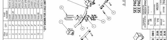
18 M S 2 2 Watson & Chalin 18

19 M S 2 2 Watson & Chalin 19
20 M S 2 2 Watson & Chalin 2

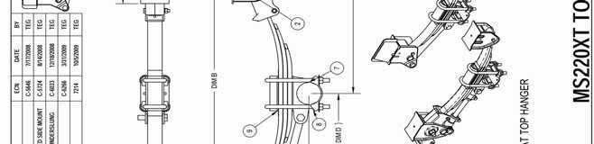
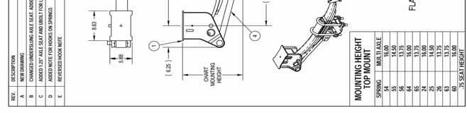
21 M S 2 5 Watson & Chalin 21
22 M S 2 5 Watson & Chalin 22


23 MS25 TWO PIECE BUSHING INSTALLATION TWO-PIECE TORQUE ARM BUSHING ASSEMBLY PROCEDURE Place Compression Washer and Rubber Bushing on head of Torque Arm bolt, and insert through openings in Hanger or axle seat and through Torque Arm end opening. Lubricants ARE NOT recommended, but if absolutely necessary, use soap and water, or just plain water. Do not use any Petroleum-Based Lubricants. Place second Bushing, and second Compression Washer on other end of Torque Arm Bolt. Start Nut on Bolt by hand. Figure 15 Figure 15 Tighten nut, partially, until all air gaps are removed between the two Compression Washers. Center and hold the Torque Arm in as close to the middle of Hanger gap as possible. Center Gap Figure 15 Carefully tighten the locknut to achieve a torque value between ft. lbs. (19-22 Nm). Be sure to always keep an equal buildup of rubber on each side of the Torque arm, and the Compression Washers. If the rubber has not built up equally, or the Torque Arm is not centered, it is strongly recommended to repeat the above steps. Do not exceed the specified torque values. The rubber will likely settle, resulting in torque readings lower than the specified values in subsequent checks. Ensure the assembly is tight and that there are no loose parts or gaps between washer, hangers and rubber bushings. Figure 15 Watson & Chalin 23

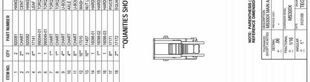
24 M S 3 Watson & Chalin 24
25 M S 3 Watson & Chalin 25
26 Appendix 1 Re-Torque Guidelines WARNING: DO NOT APPLY TORQUE TO THE BOLT HEAD SIDE OF CONNECTION (Non-Plated Clean Lubricated Thread) Torque Requirements: Apply torque to nut side of connection as specified in Table 1 below. Specified torque values are intended for non-plated lubricated threads. Use of dry or plated threads may result in bolted connection loosening prematurely and is not recommended. Table 1: Cap Screw/Bolt (Grade 8 UNF) Torque Requirements Cap screw/bolt Size 3/8 1/2 5/8 3/4 7/ /8 1 ¼ Torque MIN ft*lbs Torque MAX ft*lbs NOTE: Torque Values do not apply to air springs or lower grade fasteners. The minimum re-torque requirement for all fasteners is after the first 1, to 3, miles (1,6-4,8 kms) of operation, and again with all the annual inspections thereafter. Tighten 7/8 U-bolt nut, use pattern as shown in Figure 16 Tighten 3/4 U-bolt nut, use pattern as shown in Figure FP (54-61 NM) 2-25 FP ( NM) Figure 16 U-Bolt Torque Pattern INSTALLER RESPONSIBILITIES Installer is responsible for installing the product in accordance with Watson & Chalin specifications and installation instructions as well as establishing and providing proper vehicle components and attachments. Installer is also responsible for establishing and verifying all clearance for suspension components, brake components, axles, wheels, tires, and other vehicle components to ensure a safe and sound operation. Watson & Chalin 26

27 Watson & Chalin 27
TMC 90 SPRING SUSPENSION
 TMC 90 SPRING SUSPENSION INSTALLATION and SERVICE MANUAL TMC AUSTRALIA PTY LTD Telephone: + (61) 3 8786 3688 78 Star Crescent, P.O. Box 5028 Facsimile: + (61) 3 8786 3699 Hallam, Victoria, 3083 E-mail:
Suspension. Table of Contents
 Suspension Table of Contents Sub-Headings Safety Notice 2 Explanation of Signal Words 2 Danger 2 2 Caution 2 Description 3 Preventive Maintenance 4 Shock Absorber 7 Visual Inspection 7 Heat Test 8 Steering
INSTALLATION AND MAINTENANCE MANUAL
 IMPORTANT This manual must accompany the trailer when delivered to the end user. INSTALLATION AND MAINTENANCE MANUAL ISS Series Suspensions 347 King Street West, Ingersoll, Ontario, Canada, N5C 3K6 Ph:
TRAILER INSTALLATION INSTRUCTIONS
 TRAILER INSTALLATION INSTRUCTIONS 8A000450 DuraMax 20,000 LB. CAPACITY Link Mfg. Ltd. 223 15th St. N.E. Sioux Center, IA USA 51250-2120 www.linkmfg.com QUESTIONS? CALL CUSTOMER SERVICE 1-800-222-6283 Refer
RSS Truck Suspension Self-Steer Air-Ride Suspension System for Customer-Supplied I-Beam Axle
 RSS-2361000-Truck Suspension Self-Steer Air-Ride Suspension System for Customer-Supplied I-Beam Axle Installation and Service Manual Suspension Identification... 2 Suspension System Serial Tag Prior to
SuperTrac. Axle. Service & Maintenance. Manual
 SuperTrac Axle Service & Maintenance Manual Table of Contents Page Exploded Views Section 1: General Information General Warnings Description of Axle Models Identifications Section 2: Installation Axle
TECHNICAL PROCEDURE NON-STEERABLE SUSPENSION SYSTEMS
 TECHNICAL PROCEDURE NON-STEERABLE SUSPENSION SYSTEMS SUBJECT: Installation Instructions LIT NO: DATE: December 2003 TABLE OF CONTENTS Introduction... 2 Required Supplies... 2 Pre-Installation Checklist...
Alpha Series Front Bumper Installation Manual
 1 K Alpha Series Front Bumper Installation Manual - 2003-2009 GM 4500-5500 2 Kelderman Alpha Series Front Bumper Winch Pre-Runner Bar Not Available - Contents - Kit Numbers. (3) - Introduction. (4) - Safety...
DockMaster 400 (DM400) Owner s Manual. Trailer Suspensions. Installation Instructions Maintenance Instructions Service Parts
 Owner s Manual. Trailer Suspensions. Installation Instructions Maintenance Instructions Service Parts") Trailer Suspensions Owner s Manual DockMaster 400 (DM400) Installation Instructions Maintenance Instructions Service Parts Document #: D712054 Revision: C Revision Date: 12/15 1-800-753-0050 www. r eycogranning.
Trailer Suspensions Owner s Manual DockMaster 400 (DM400) Installation Instructions Maintenance Instructions Service Parts Document #: D712054 Revision: C Revision Date: 12/15 1-800-753-0050 www. r eycogranning.
Trailer Suspension Series Installation Instructions. Advancing the Practical Application of Suspension Technology
 900-9700 Trailer Suspension Series Installation Instructions Advancing the Practical Application of Suspension Technology Springfield, MO n (800) -882 n (17) 82-012 Fax (17) 82-217 n www.hutchensindustries.com
Extreme Duty Grapple (Rock, Skeleton, Scrap & Tine) Operation and Maintenance Manual
 Operation and Maintenance Manual") Extreme Duty Grapple (Rock, Skeleton, Scrap & Tine) Operation and Maintenance Manual Revision Date: May 12, 2017 Skid Pro PO Box 982 Alexandria, MN 56308 Toll Free: 877-378-4642 www.skidpro.com TABLE OF
Extreme Duty Grapple (Rock, Skeleton, Scrap & Tine) Operation and Maintenance Manual Revision Date: May 12, 2017 Skid Pro PO Box 982 Alexandria, MN 56308 Toll Free: 877-378-4642 www.skidpro.com TABLE OF
Before equipment use, please read this operation manual carefully. Serial Number: Date Purchased:
 Pushed & Geared Trolleys OPERATION MANUAL This operation manual is intended as an instruction manual for trained personnel who are in charge of installation, maintenance, repair etc. Before equipment use,
BX7322 Adventurer Tow Bar Operator Manual & Installation Instructions. (5,000 lb) 2 Inch Coupler
 2 Inch Coupler") Operator Manual & Installation Instructions (5,000 lb) 2 Inch Coupler General Information DO NOT INSTALL, OPERATE OR USE THIS EQUIPMENT UNTIL THE FOLLOWING OPERATING AND SAFETY INSTRUCTIONS HAVE BEEN READ
Operator Manual & Installation Instructions (5,000 lb) 2 Inch Coupler General Information DO NOT INSTALL, OPERATE OR USE THIS EQUIPMENT UNTIL THE FOLLOWING OPERATING AND SAFETY INSTRUCTIONS HAVE BEEN READ
INSTALLATION INSTRUCTIONS
 INSTALLATION INSTRUCTIONS 8A000729 DuraLift 13.5 13,500 LB. CAPACITY Link Mfg. Ltd. 223 15th St. N.E. Sioux Center, IA USA 51250-2120 www.linkmfg.com QUESTIONS? CALL CUSTOMER SERVICE 1-800-222-6283 Refer
Installation Instructions
 Installation Instructions For 3500HD & IMPORTANT NOTE The Axle Less suspension provides many advantages and permits many innovative designs for trailers. There is no thru axle and therefore the two sides
BX7322 Adventurer Tow Bar Operator Manual & Installation Instructions
 Please visit www.blueox.com for the latest version of these installation instructions. BX7322 Operator Manual & Installation Instructions Serial Number (5,000 lb) 2 Inch Coupler 292-1263 Rev J Page 1 of
INSTALLATION AND MAINTENANCE MANUAL. ROADTRACKtm RTD SUSPENSION
 INSTALLATION AND MAINTENANCE MANUAL ROADTRACKtm RTD SUSPENSION Roadtrack RTD Series Suspension The ROADTRACK series suspension system is a three point system available in undermount or underslung set-ups.
BX7322 Adventurer Tow Bar Operator Manual & Installation Instructions
 Please visit www.blueox.com for the latest version of these installation instructions. BX7322 Operator Manual & Installation Instructions Serial Number (5,000 lb) 2 Inch Coupler 292-1263 Rev J Page 1 of
TMC 11T Air Suspension Service Manual
 TMC 11T Air Suspension Service Manual The Group Disclaimer Versioning The author and publisher have made their best efforts to prepare this manual, and the information contained in this manual is current
TMC CS Mechanical Suspension Service Manual
 TMC CS Mechanical Suspension Service Manual The Group Disclaimer Versioning The author and publisher have made their best efforts to prepare this manual, and the information contained in this manual is
<THESE INSTRUCTIONS MUST BE GIVEN TO THE END USER> B&W
 B&W Trailer Hitches 1216 Hawaii Rd / PO Box 186 Humboldt, KS 66748 Turnoverball Gooseneck Hitch Installation Instructions MODEL 1314 2013 2014 RAM 3500
4331 EUCALYPTUS AVE. ~~ CHINO, CA Fax FORD F-250/350 SUPER DUTY 4 WHEEL DRIVE FTS
 4331 EUCALYPTUS AVE. ~~ CHINO, CA 91710 909-597-7800 Fax 909-597-7185 2000-2003 FORD F-250/350 SUPER DUTY 4 WHEEL DRIVE FTS421-1 5.5 & 8 LIFT BOX KIT PARTS LIST: 1 EA. TRACK ARM BRKT. FT423-100 1 EA. PITMAN
Installation Instructions READ THOROUGHLY BEFORE BEGINNING Signature Series Rail Kit Dodge Ram Trucks-all, including Mega-cabs
 INDEX Failure to follow all of these instructions may result in death or serious injury!. GUIDELINES FOR MATCHING TOW VEHICLE AND TRAILER. Pages -. DRILLED AND BOLTED INSTALLATION FIGURE. Page 4. NO-DRILL,
DODGE 3 SUSPENSION LIFT KIT
 921351200 Kit Contents: 9280:Front Coil Springs 1351BOX1: Upper Control Arms Lower Control Arms Sway bar Brackets Brake Proportioning Valve Bracket Track Bar Relocation Bracket 1351BOX2: 5.75 Blocks U-bolt
<THESE INSTRUCTIONS MUST BE GIVEN TO THE END USER> 1 2 " X 1 1 2" Hex Cap Screws " Split Lock Washers " Threaded block 4
 B&W Trailer Hitches 1216 Hawaii Rd / PO Box 186 Humboldt, KS 66748 P:620.473.3664 F:620.473.3766 Companion Hitch Installation Instructions 20,000 LBS.
INSTALLATION INSTRUCTIONS MOUNTING KIT FOR ELITE SERIES
 INSTALLATION INSTRUCTIONS MOUNTING KIT FOR ELITE SERIES DO NOT EXCEED VEHICLE MANUFACTURER S RATING FOR 5th WHEEL TOWING OR MAXIMUM GROSS TRAILER WEIGHT OF 18,000lb. / 8160kg. DEALER/INSTALLER: (1) Provide
INSTALLATION INSTRUCTIONS MOUNTING KIT FOR ELITE SERIES
 INSTALLATION INSTRUCTIONS MOUNTING KIT FOR ELITE SERIES DEALER/INSTALLER: (1) Provide this Manual to end user. END USER: (1) Save this Manual for future reference. (2) Pass on copies of Manual to any other
<THESE INSTRUCTIONS MUST BE GIVEN TO THE END USER> B&W Trailer Hitches 1216 Hawaii Rd / PO Box 186 Humboldt, KS P: F:
 B&W Trailer Hitches 6 Hawaii Rd / PO Box 86 Humboldt, KS 6678 P:60.7366 F:60.73766 Turnoverball Gooseneck Hitch Installation Instructions MODEL 38 0 06
INSTALLATION AND MAINTENANCE MANUAL E6100 SERIES SPRING SUSPENSION
 INSTALLATION AND MAINTENANCE MANUAL E6100 SERIES SPRING SUSPENSION E6100 Series Spring Suspension The E6100 series suspension system is a three point system available in undermount or underslung set-ups.
OWNER S GUIDE 8A DURALIFT II 13,200 LB. CAPACITY. Link Mfg. Ltd th St. N.E. Sioux Center, IA USA
 OWNER S GUIDE 8A000715 DURALIFT II 13,200 LB. CAPACITY Link Mfg. Ltd. 223 15th St. N.E. Sioux Center, IA USA 51250-2120 www.linkmfg.com QUESTIONS? CALL CUSTOMER SERVICE 1-800-222-6283 DEALER / INSTALLER:
Predelivery Instructions
 PINK Predelivery Instructions SR5030 Split-Row Planter Manufacturing, Inc. P.O. Box 5060 Salina, Kansas 67402-5060! Read this manual entirely. When you see this symbol, the subsequent instructions and
Alpha Series Front Bumper Installation Manual
 1 K Alpha Series Front Bumper Installation Manual - 2017 Ford Super Duty 2 Kelderman Alpha Series Front Bumper Light Winch - Contents - Kit Numbers. (3) - Introduction. (4) - Safety... (5) - Bumper Removal......
(877) MON-FRI 7AM-5PM PST OR WEBSITE: ReadyLIFT.COM **Please retain this document in your vehicle at all times**
 MON-FRI 7AM-5PM PST OR WEBSITE: ReadyLIFT.COM **Please retain this document in your vehicle at all times**") IF YOUR ReadyLIFT PRODUCT IS MISSING A OR HAS A DAM- AGED PART, PLEASE CONTACT CUSTOMER SERVICE DIRECTLY. For warranty issues please return to the place of installation and contact ReadyLIFT. A NEW REPLACEMENT
IF YOUR ReadyLIFT PRODUCT IS MISSING A OR HAS A DAM- AGED PART, PLEASE CONTACT CUSTOMER SERVICE DIRECTLY. For warranty issues please return to the place of installation and contact ReadyLIFT. A NEW REPLACEMENT
MODEL LR-2066 & LR-2866A HOIST INSTALLATION AND OPERATION MANUAL
 TRUCK BODIES & EQUIPMENT INTERNATIONAL, Inc. Website: www.rugbymfg.com E-mail: sales@rugbymfg.com Phone: 1-800-869-9162 03 5839 MODEL LR-2066 & LR-2866A HOIST INSTALLATION AND OPERATION MANUAL Hoist Serial
Model 320 / 320A Hinge Assembly
 MANUFACTURING CO. THE FIRST NAME IN QUALITY COUPLINGS Installation, Inspection, Operation & Maintenance Guide Model 320 / 320A Hinge Assembly IMPORTANT Read these instructions completely before installing,
<THESE INSTRUCTIONS MUST BE GIVEN TO THE END USER> B&W
 B&W Trailer Hitches 6 Hawaii Rd / PO Box 86 Humboldt, KS 6678 P:60.7366 F:60.86.03 Turnoverball Gooseneck Hitch Installation Instructions MODEL 38 0 08
HR-520 HOIST. Installation & Operation Manual. To Be Filled In By Installer. Pump Installation And Operation Manual#: In Service Date: Dealer:
 Website: www.tbei.com E-mail: sales@tbei.com Phone: 1-800-869-9162 Rugby 1-800-255-4345 DuraClass 1-800-533-0494 Crysteel HR-520 HOIST Installation & Operation Manual To Be Filled In By Installer Hoist
<THESE INSTRUCTIONS MUST BE GIVEN TO THE END USER> BASE BOLT BAG (RVB3500) ITEM DESCRIPTION QTY. 1 2 " X 1 1 2" Hex Cap Screws 16
 ITEM DESCRIPTION QTY. 1 2 X 1 1 2 Hex Cap Screws 16") B&W Trailer Hitches 1216 Hawaii Rd / PO Box 186 Humboldt, KS 66748 P:620.473.3664 F:620.869.9031 Companion Hitch Installation Instructions 20,000 LBS.
B&W Trailer Hitches 1216 Hawaii Rd / PO Box 186 Humboldt, KS 66748 P:620.473.3664 F:620.869.9031 Companion Hitch Installation Instructions 20,000 LBS.
KI AIR SUSPENSION (wide Pivot Bush)
") KI AIR SUSPENSION (wide Pivot Bush) Contents 1. Pre-assembly Considerations 2. Welding Instructions Chassis Connection 3. Tightening Instruction 4. Axle Alignment 5. Maintenance www.khitch.com.au Uncontrolled
KI AIR SUSPENSION (wide Pivot Bush) Contents 1. Pre-assembly Considerations 2. Welding Instructions Chassis Connection 3. Tightening Instruction 4. Axle Alignment 5. Maintenance www.khitch.com.au Uncontrolled
OWNERS MANUAL GM C4500/C5500 4X2 REAR STABILIZER BAR KIT 2006-NEWER MODELS. For Installation with 8M and 8M UltraRide Suspension
 OWNERS MANUAL GM C4500/C5500 4X2 REAR STABILIZER BAR KIT 2006-NEWER MODELS For Installation with 8M000090 and 8M000105 UltraRide Suspension Questions? Contact this Professional Installer : Link Kit Part
(800) MON-FRI 7AM-5PM PST OR WEBSITE: ReadyLIFT.COM **Please retain this document in your vehicle at all times**
 MON-FRI 7AM-5PM PST OR WEBSITE: ReadyLIFT.COM **Please retain this document in your vehicle at all times**") IF YOUR ReadyLIFT PRODUCT IS MISSING A PART OR HAS A DAMAGED PART, PLEASE CONTACT CUSTOMER SERVICE DIRECTLY. A NEW REPLACEMENT PART WILL BE SENT TO YOU IMMEDIATELY (800)549-4620 MON-FRI 7AM-5PM PST OR
IF YOUR ReadyLIFT PRODUCT IS MISSING A PART OR HAS A DAMAGED PART, PLEASE CONTACT CUSTOMER SERVICE DIRECTLY. A NEW REPLACEMENT PART WILL BE SENT TO YOU IMMEDIATELY (800)549-4620 MON-FRI 7AM-5PM PST OR
INSTALLATION INSTRUCTIONS MOUNTING KIT GENERAL MOTORS Chevrolet Silverado/GMC Sierra 2500HD & 3500HD
 INSTALLATION INSTRUCTIONS MOUNTING KIT GENERAL MOTORS 2001-2006 Chevrolet Silverado/GMC Sierra 2500HD & 3500HD DEALER/INSTALLER: (1) Provide this Manual to end user. END USER: (1) Save this Manual for
Air Ride Single Point Suspension. Installation and Service Manual
 RAR-254 Air Ride Single Point Suspension Installation and Service Manual Suspension Identification... 2 Suspension System/Axle Serial Tag Installation... 3 Prior to Installation Suspension Mounting Troubleshooting
XJ CHEROKEE LIFT KIT
 92162300 84-01 4.5 XJ CHEROKEE LIFT KIT Thank you for choosing Rough Country for your suspension needs. Rough Country recommends a certified technician installs this system. In addition to these instructions,
HR-540/HR-550 HOIST Installation & Operation Manual
 Website: www.tbei.com E-mail: sales@tbei.com Phone: 1-800-869-9162 Rugby 1-800-255-4345 DuraClass 1-800-533-0494 Crysteel HR-540/HR-550 HOIST Installation & Operation Manual To Be Filled In By Installer
Once properly aligned weld axle saddles to axle using welding practice as below.
 INSTALLATION & MAINTENANCE GUIDE 50 Series Suspensions Shackle bolts and rocker pivot bolts fitted with Nyloc type nuts must be tightened firmly allowing for rotational movement of bushed components. All
Extreme Duty Grapple (Rock, Skeleton, Scrap & Tine) Operation and Maintenance Manual
 Operation and Maintenance Manual") Extreme Duty Grapple (Rock, Skeleton, Scrap & Tine) Operation and Maintenance Manual Revision Date: July 2017 Skid Pro PO Box 982 Alexandria, MN 56308 Toll Free: 877-378-4642 www.skidpro.com TABLE OF CONTENTS
Extreme Duty Grapple (Rock, Skeleton, Scrap & Tine) Operation and Maintenance Manual Revision Date: July 2017 Skid Pro PO Box 982 Alexandria, MN 56308 Toll Free: 877-378-4642 www.skidpro.com TABLE OF CONTENTS
15-17 FORD MUSTANG GT
 15-17 FORD MUSTANG GT IMPORTANT! WARRANTY AND Please Forward All Information to Consumer Be sure to review the enclosed instructions prior to beginning the installation process. If you have any questions
Installation and. Maintenance Instructions. Model Front Axle Air-Ride. Suspension System
 Installation and Maintenance Instructions Model 1200 Front Axle Air-Ride Suspension System Installation Instructions Model 1200 Company Profile COMPANY PROFILE Tuthill Transport Technologies is the Line
15-17 FORD MUSTANG GT
 15-17 FORD MUSTANG GT IMPORTANT! WARRANTY AND Please Forward All Information to Consumer Be sure to review the enclosed instructions prior to beginning the installation process. If you have any questions
RSS-233T - 13K Trailer Self-Steering Air-Ride Suspension
 RSS-233T - 13K Trailer Self-Steering Air-Ride Suspension Installation and Service Manual Suspension Identification... 2 Suspension System Serial Tag Installation... 3 Torque Specifications Prior to Installation
FORD F-250, F-350, 4WD 2 COIL SPRING LEVELING KIT INSTALLATION INSTRUCTIONS
 3651 N. Highway 89 Chino Valley, AZ 86323 (928) 636-7080 www.p-a-g.net FORD F-250, F-350, 4WD 2 COIL SPRING LEVELING KIT INSTALLATION INSTRUCTIONS 2008 KIT# FL223PA Many states now have laws restricting
MOUNTING RAILS ***DO NOT EXCEED VEHICLE MANUFACTURER'S RECOMMENDED TOWING CAPACITY.***
 10/30/2017 PAGE 1 OF 6 Parts List ITEM QTY PART NUMBER DESCRIPTION 1 2 CM-16150-MR MOUNTING RAILS 2 2 CM-16150-FB.375" FRONT BRACKET 3 1 CM-16150-PSRB.375" PASSENGER SIDE REAR BRACKET 4 1 CM-16150-DSRB.375"
<THESE INSTRUCTIONS MUST BE GIVEN TO THE END USER> B&W
 B&W Trailer Hitches 1216 Hawaii Rd / PO Box 186 Humboldt, KS 66748 P:620.473664 F:620.869.9031 Turnoverball Gooseneck Hitch Installation Instructions
TMC 75 SPRING SUSPENSION
 TMC 75 SPRING SUSPENSION SERVICE MANUAL TMC Australia Pty Ltd Telephone: + 61 3 8786 3688 78 Star Crescent Facsimile: + 61 3 8786 3699 Hallam E-Mail: info@tmcaus.com.au Victoria 3803 Australia www.tmcaustralia.com.au
OWNERS MANUAL. GMC C K AND 19K GVW CHASSIS CAB 2004-NEWER MODELS (Link Part No. 8M000050) PROUDLY INSTALLED BY : COMPANY : INSTALLER SIGNATURE :
 PROUDLY INSTALLED BY : COMPANY : INSTALLER SIGNATURE :") OWNERS MANUAL GMC C5500 15K AND 19K GVW CHASSIS CAB 2004-NEWER MODELS (Link Part No. 8M000050) Link Mfg. Ltd. 223 15th St. N.E. Sioux Center, IA USA 51250-2120 (712) 722-4868 Fax (712) 722-4779 QUESTIONS?
OWNERS MANUAL GMC C5500 15K AND 19K GVW CHASSIS CAB 2004-NEWER MODELS (Link Part No. 8M000050) Link Mfg. Ltd. 223 15th St. N.E. Sioux Center, IA USA 51250-2120 (712) 722-4868 Fax (712) 722-4779 QUESTIONS?
15-17 FORD MUSTANG GT
 15-17 FORD MUSTANG GT IMPORTANT! WARRANTY AND Please Forward All Information to Consumer Be sure to review the enclosed instructions prior to beginning the installation process. If you have any questions
3 Axles and brakes. 3.1 Function and construction of the axles Construction Function
 3 Axles and brakes 3.1 Function and construction of the axles 3.1.1 Function Each wheel has an independent suspension system in the axle body (1), so that individual wheel suspension is provided. The swinging
INSTALLATION INSTRUCTIONS
 INSTALLATION INSTRUCTIONS 2005-2012 Nissan Xterra/Frontier / Pathfinder PART NUMBERS: NP17500, NP17525, NP17550 FRONTIER PARTS & CORRESPONDING HARDWARE LIST XTERRA PATHFINDER ABOVE LISTED 1/2 Metal Lock
Model 3400 ATTENTION: WARNING
 B&W Trailer Hitches 1216 Hawaii Road / PO Box 186 Humboldt, KS 66748 P:620.473.3664 F:620.473.3766 NOTE: We recommend reading instructions before beginning the installation. Companion Slider Hitch Installation
RSS-233T - 13K Trailer Self-Steering Air-Ride Suspension
 RSS-233T - 13K Trailer Self-Steering Air-Ride Suspension Installation and Service Manual Suspension Identification... 2 Suspension System Serial Tag Installation... 3 Torque Specifications Prior to Installation
GM P/U, Blazer, Suburban, 1 Ton 4WD 4-6 Kits
 92114500 1973-87 GM P/U, 1973-91 Blazer, Suburban, 1 Ton 4WD 4-6 Kits Thank you for choosing Rough Country for all of your suspension needs. Rough Country recommends a certified technician installs this
KT AIR SUSPENSION (Engineering Lit. No. KL006)
") KT AIR SUSPENSION (Engineering Lit. No. KL006) KT250 T KT300T KT250U KT300U Contents 1. Preassembly Considerations 2. KT Welding Instruction Axle Connection o Engineering LIT No: KL004 3. KT Welding Instruction
KT AIR SUSPENSION (Engineering Lit. No. KL006) KT250 T KT300T KT250U KT300U Contents 1. Preassembly Considerations 2. KT Welding Instruction Axle Connection o Engineering LIT No: KL004 3. KT Welding Instruction
This 6 suspension system was developed for 37x12.50x17 tire on an after market wheel w/ 4.5 back spacing.
 Thank you for choosing Rough Country for your suspension needs. 921560200C *1560BAG4* 1560BAG4 2017 F250 6 4-LINK SUSPENSION KIT Rough Country recommends a certified technician installs this system. In
270PK SERVICE GUIDELINES
 270 Coupling THE FIRST NAME IN QUALITY COUPLINGS 270PK SERVICE GUIDELINES BEFORE GETTING STARTED: This procedure should only be performed by a qualified mechanic. Measure the wear on the coupling s pintle
/3500 Dodge 5 Long Arm Kit
 92138800A 03-07 2500/3500 Dodge 5 Long Arm Kit Thank you for choosing Rough Country Suspension for your Off Road needs. Rough Country recommends a certified technician installs this system. In addition
RSS K Truck Self-Steering Air-Ride Suspension
 RSS-233-20K Truck Self-Steering Air-Ride Suspension Installation and Service Manual Suspension Identification... 2 Suspension System Serial Tag Installation... 3 Prior to Installation Suspension Mounting
(800) MON-FRI 7AM-5PM PST OR WEBSITE: ReadyLIFT.COM **Please retain this document in your vehicle at all times**
 MON-FRI 7AM-5PM PST OR WEBSITE: ReadyLIFT.COM **Please retain this document in your vehicle at all times**") IF YOUR ReadyLIFT PRODUCT IS MISSING A OR HAS A DAM- AGED PART, PLEASE CONTACT CUSTOMER SERVICE DIRECTLY. For warranty issues please return to the place of installation and contact ReadyLIFT. A NEW REPLACEMENT
IF YOUR ReadyLIFT PRODUCT IS MISSING A OR HAS A DAM- AGED PART, PLEASE CONTACT CUSTOMER SERVICE DIRECTLY. For warranty issues please return to the place of installation and contact ReadyLIFT. A NEW REPLACEMENT
BX4330 Acclaim Tow Bar Operator Manual & Installation Instructions
 Operator Manual & Installation Instructions (5,000 lb) 2 Inch Coupler General Information DO NOT INSTALL, OPERATE OR USE THIS EQUIPMENT UNTIL THE FOLLOWING OPERATING AND SAFETY INSTRUCTIONS HAVE BEEN READ
97-06 JEEP TJ/LJ LONG ARM UPGRADE KIT
 921663U00 97-06 JEEP TJ/LJ LONG ARM UPGRADE KIT Thank you for choosing Rough Country for your suspension needs. This kit is an upgrade kit only. This kit includes frame mounting points and adjustable long
RSS-232/232T - 8K-10K-13K Self-Steering Auxiliary Axle Suspension
 RSS-232/232T - 8K-10K-13K Self-Steering Auxiliary Axle Suspension Installation and Service Manual Suspension Identification... 2 Suspension System Serial Tag Installation... 3 Prior to Installation Suspension
RSS-232/232T 20K Truck and Trailer Self-Steering Auxiliary Axle Suspension
 RSS-232/232T 20K Truck and Trailer Self-Steering Auxiliary Axle Suspension RSS-232 - Truck suspension shown Installation and Service Manual Suspension Identification... 2 Suspension System Serial Tag Installation...
B&W Trailer Hitches 1216 Hawaii Road / PO Box 186 Humboldt, KS P: F: " Split Lock Washers 8
 B&W Trailer Hitches 1216 Hawaii Road / PO Box 186 Humboldt, KS 66748 P:620.473.3664 F:620.869.9031 NOTE: We recommend reading instructions before beginning the installation. Companion Slider Hitch Installation
Parts & Installation. Slider Series Featuring The Hutch P 3 Pneumatic Pin Puller
 The World s Leading Manufacturer Of Trailer Sliders For Over Three Decades. Slider Series Featuring The Hutch P 3 Pneumatic Pin Puller Parts & Installation Advancing the Practical Application of Suspension
Frame Bracket Side Plate Repair Procedures
 Revised 02-08 Service Parts Instructions Frame Bracket Side Plate Repair Procedures Meritor RideStar RHP Series Single-Axle and Sliding Tandem Trailer Air Suspension Systems Revised 1 Service 02-08 Parts
Model 3770 WARNING. Failure to comply with the safety information in these instructions could result in serious injury or death.
 B&W Trailer Hitches 1216 Hawaii Road / PO Box 186 Humboldt, KS 66748 P:620.473.3664 See Limited Lifetime Warranty at F:620.869.9031 bwtrailerhitches.com/warranty NOTE: We recommend reading instructions
TECHNICAL BULLETIN
 Stock No. H26 - MODULAR CENTER HANGER MOUNTING KIT, SPLIT BUSHING Stock No. H32 - MODULAR CENTER HANGER MOUNTING KIT Page 1 of 10 CONCEPT: This mounting kit, when used with our standard L02 load cells,
ATV TRACK KIT. Operator s Manual Installation Instructions Service Instructions Replacement Parts List. Effective Date: October, 2012
 p/n 2258-642 ATV TRACK KIT Operator s Manual Installation Instructions Service Instructions Replacement Parts List Track Assembly Kits (p/n 1436-204) Mounting Assembly Kits (p/n 1436-205) 1436-815) Effective
/3500 Dodge 5 Long Arm Kit
 92137900A 11-12 2500/3500 Dodge 5 Long Arm Kit Thank you for choosing Rough Country Suspension for your Off Road needs. Rough Country recommends a certified technician installs this system. In addition
Colorado/ Canyon 4, 5, and 6 Lift Kit
 *1221BAG3* 1221BAG3 921221200B 2015-16 Colorado/ Canyon 4, 5, and 6 Lift Kit Thank you for choosing Rough Country for all of your suspension needs. Rough Country recommends a certified technician installs
Required tools General hand tools 21/64" drill bit Torque wrench Threadlocker Center punch
 Slipper Spring Kit (part numbers 2560, 2570 and 2580) Item Qty Part number Description 1... 8... 350054-50...3/8-16 x 1" grade 8 self-tapping screw 2... 4... 350084-00...7/16-14 x 4" grade 5 3... 6...
<THESE INSTRUCTIONS MUST BE GIVEN TO THE END USER> B&W Trailer Hitches 1216 Hawaii Road / PO Box 186 Humboldt, KS P: F:
 B&W Trailer Hitches 26 Hawaii Road / PO Box 86 Humboldt, KS 66748 P:620.473.3664 F:620.869.903 Ford OEM Mount System Installation Instructions 20,000
Technical Support Line: (952) Hanover Ave. Lakeville, MN
 Hanover Ave. Lakeville, MN") Technical Support Line: (952) 985-5675 Email: Sales@QA1.net 21730 Hanover Ave. Lakeville, MN 55044 www.qa1.net INSTALLATION INSTRUCTIONS QA1 1967-1979 Mopar A-Body Rear 6 link Conversion System QA1 p/n
Technical Support Line: (952) 985-5675 Email: Sales@QA1.net 21730 Hanover Ave. Lakeville, MN 55044 www.qa1.net INSTALLATION INSTRUCTIONS QA1 1967-1979 Mopar A-Body Rear 6 link Conversion System QA1 p/n
INSTALLATION INSTRUCTION 88092
 INSTALLATION INSTRUCTION 88092 FOR RANCHO SUSPENSION SYSTEM RS6592: NISSAN XTERRA & 2WD FRONTIER READ ALL INSTRUCTIONS THOROUGHLY FROM START TO FINISH BEFORE BEGINNING INSTALLATION Rev C IMPORTANT NOTES!
88-98 GM 2-3 SUSPENSION KIT
 92754500 Thank you for choosing Rough Country for your suspension needs. 88-98 GM 2-3 SUSPENSION KIT Rough Country recommends a certified technician installs this system. In addition to these instructions,
JSK 34. Installation and operating instructions
 JSK 34 EN Installation and operating instructions Table of contents 1 Explanation of symbols... 3 2 Safety information... 4 2.1 Safety information for operation... 4 2.2 Safety information for installation...
TAG LIFT AXLE SUSPENSION SERVICE MANUAL- 37 T
 TAG LIFT AXLE SUSPENSION SERVICE MANUAL- 37 T ` Page 0 CONTENT SI.NO Description Page No. 1 Suspension Specification 2 2 Pre-Installation Notes 2 3 Suspension Parts Description 3 4 Dismantling Procedure
Installation. Slider Series Parts & The World s Leading Manufacturer Of Trailer Sliders For Over Three Decades.
 The World s Leading Manufacturer Of Trailer Sliders For Over Three Decades. 8500 Slider Series Parts & Installation Advancing the Practical Application of Suspension Technology Springfield, MO n (800)
RSS-233T - 20K Trailer Self-Steering Air-Ride Suspension
 RSS-233T - 20K Trailer Self-Steering Air-Ride Suspension Installation and Service Manual Suspension Identification... 2 Suspension System Serial Tag Installation... 3 Prior to Installation Suspension Mounting
Please visit for the latest version of these installation instructions.
 Please visit www.blueox.com for the latest version of these installation instructions. BX1986 Please read BOTH these and the General Information sheet prior to installing or operating this equipment. 1.
INSTALLATION INSTRUCTIONS
 214205 INSTALLATION INSTRUCTIONS 8-27-2015 REV.A PART # DESCRIPTION 7929 Lincoln Ave. Riverside, CA 92504 Phone: 951.689.ICON Fax: 951.689.1016 214205 14-UP RAM 2500 4.5 BOX KIT COMPONENTS INCLUDED (1)
INSTALLATION INSTRUCTIONS MOUNTING KIT GENERAL MOTORS Chevrolet Silverado Sierra, GMC 3500HD; Silverado
 INSTALLATION INSTRUCTIONS MOUNTING KIT GENERAL MOTORS 2001-04 Chevrolet Silverado Sierra, GMC 3500HD; 99-2000 Silverado DEALER/INSTALLER: (1) Provide this Manual to end user. END USER: (1) Save this Manual
INSTALLATION INSTRUCTIONS MOUNTING KIT COMMERCIAL TRUCK FOR 34 OUTSIDE FRAME WIDTH ONLY. Front of vehicle
 INSTALLATION INSTRUCTIONS MOUNTING KIT COMMERCIAL TRUCK FOR 34 OUTSIDE FRAME WIDTH ONLY DEALER/INSTALLER: (1) Provide this Manual to end user. END USER: (1) Save this Manual for future reference. (2) Pass
*1234BAG1 1234BAG WD CHEVY/GM LIFT N200
 *1234BAG1 1234BAG1 921234N200 99-06 2WD CHEVY/GM 1500 6 LIFT Thank you for choosing Rough Country for all of your suspension needs. Rough Country recommends a certified technician installs this system.
15-18 FORD MUSTANG GT
 15-18 FORD MUSTANG GT IMPORTANT! WARRANTY AND Please Forward All Information to Consumer Be sure to review the enclosed instructions prior to beginning the installation process. If you have any questions
JK HD Skid Plate for Rear Falcon Shocks
 1 JK HD Skid Plate for Rear Falcon Shocks Kit # 36-07-01-300 Tools needed: Important Notes: Prior to beginning this or any installation read these instructions to familiarize yourself with the required
*1550BAG5* 1550BAG F & 6 SUSPENSION LIFT KIT C. Thank you for choosing Rough Country for your suspension needs.
 Thank you for choosing Rough Country for your suspension needs. 921550200C *1550BAG5* 1550BAG5 2017 F250 4.5 & 6 SUSPENSION LIFT KIT Rough Country recommends a certified technician installs this system.
Technical Information
 Product Group: TRAILERS Model: ALL MODELS This bulletin is provided for technical reference and service related updates. If you have any questions, comments or do not wish to receive these e-mails, please
(800) MON-FRI 7AM-5PM PST OR WEBSITE: ReadyLIFT.COM **Please retain this document in your vehicle at all times**
 MON-FRI 7AM-5PM PST OR WEBSITE: ReadyLIFT.COM **Please retain this document in your vehicle at all times**") IF YOUR ReadyLIFT PRODUCT IS MISSING A PART OR HAS A DAMAGED PART, PLEASE CONTACT CUSTOMER SERVICE DIRECTLY. A NEW REPLACEMENT PART WILL BE SENT TO YOU IMMEDIATELY (800)549-4620 MON-FRI 7AM-5PM PST OR
IF YOUR ReadyLIFT PRODUCT IS MISSING A PART OR HAS A DAMAGED PART, PLEASE CONTACT CUSTOMER SERVICE DIRECTLY. A NEW REPLACEMENT PART WILL BE SENT TO YOU IMMEDIATELY (800)549-4620 MON-FRI 7AM-5PM PST OR
PRODUCT USE INFORMATION
 921654300 Thank you for choosing Rough Country for your suspension needs. *65430BAG1* 65430BAG1 JEEP JL 3.5 Control Arm Drop Suspension Kit Rough Country recommends a certified technician install this