Disassembling and assembling PAH , PAHT and PAHT G
|
|
|
- Samson Stokes
- 5 years ago
- Views:
Transcription


1 MAKING MODERN LIVING POSSIBLE Instruction Disassembling and assembling PAH , PAHT and PAHT G danfoss.high-pressurepumps.com
2 Table of Contents 1. Disassembling Inspection Port plate and valve plate Pistons Cylinder barrel Housing Swash plate Assembling Spare parts list for PAH / PAHT Exploded view PAH / PAHT Spare parts list for PAHT G Exploded view PAHT G Tool sets Note: If the pump is dismantled during the warranty period, the pump is no longer under warranty. This document covers the instructions for disassembling and assembling the axial piston pumps PAH / PAHT / PAHT G Tools provided with tool set 180Z0235: Shaft bush, torpedo Press bush Ø18 (Plastic) 2


3 1. Disassembling 1. Tools required for dismantling. 2. Remove the parallel key and unscrew the front cover. 3. Dismantle the front cover using a vice. 4. Remove the shaft seal using two screwdrivers. 5. Remove the two small O-rings from the flange. Remove the seal from the front cover using a screwdriver. 6. Unscrew the four screws for the housing. 3


4 7. Remove the housing. 8. Remove the cylinder barrel. 9. Remove the pistons and the retainer plate from the cylinder barrel. 10. Remove the retainer guide. 11. Remove the spring guide. 12. Remove the spring. 4


. 18.")

5 13. Loosen the valve plate using two screwdrivers. Place one of the screwdrivers in the slot of the valve plate. 14. Remove the valve plate. 15. Remove the five O-rings and the five back-up O-rings. 16. Remove the port plate from the flange. 17. Wash all parts and replace all seals (inclusive shaft seal). 18. Inspect all parts carefully (see Inspection ) and replace any worn parts. 19. If the pump has failed, the reason for the failure must be found and fixed before the repaired pump is re-installed. 5

6 Housing with swash plate and bearing Flange Retainer plate Pistons Spring Plugs Front cover Front cover crews Valve plate with sealing Spring guide Retainer guide Cylinder barrel Shaft seal Port plate 6


7 2. Inspection 2.1 Port plate and valve plate 1. Neither port plate nor valve plate must show any sign of wear. 2. Hold a ruler against the surface of the plates and check the tightness against a light source. 3. Check that both O-rings and back-up rings are not broken and do not show severe wear. 2.2 Pistons 1. The play in the ball and socket joint must not exceed 0.1 mm. 2. The thickness of the piston shoes must be at least 4.1 mm. 3. Hold a ruler against the surfaces of the piston shoes to check that the surfaces are even and smooth and without any scratches. 4. PAHT only: It is acceptable that the (black) treated surfaces of the pistons are partly worn off. 7

. 2.")
8 2.3 Cylinder barrel 1. Check the outer bearing surface for large wear grooves (not critical). 2. Check that the bushings are free from seizure and large scratches. 3. Ensure that the pistons can move freely in the bushings. 2.4 Housing 1. Check that the swash plate surface is smooth and without any big scratches (depth more than 0.1 mm). 2. Check the bearing (the black part) for large wear grooves (not critical)


9 2.5 Swash plate Mounted swash plate: 1. Unscrew center bolt from the swash plate. 2. Remove swash plate and guide pin. Guide pin 9


10 3. Assembling WARNING: Do not use silicone when assembling the pump. Do not reuse disassembled O-rings; they might be damaged. Always use new O-rings. Important: It is essential that the pump is serviced in conditions of absolute cleanliness. All parts must be absolute clean before mounting. 1. Lubrication: To prevent seizing-up, lubricate all threads with PTFE lubrication type. O-rings inside pump may be lubricated only with clean filtered water. O-rings for port flange, mounting flange and flushing valve must be lubricated. It is important to lubricate ALL parts to be assembled with clean filtered water (Especially all PEEK parts). 2. Parts and tools required for assembly. Check that all parts are OK. Replace all seals. 3. Mount the O-ring on the flange. 4. Mount the port plate in its right position using the pin as guide. Guide pin 10


11 5. Mount the valve plate with seals on the cylinder barrel. 6. Press the valve plate into the cylinder barrel using a piece of plastic. 7. Check that the gap between the cylinder barrel and the valve plate is mm. 8. Mount the cylinder barrel in the flange. 9. Mount the spring in the centre hole. 10. Mount the spring guide. 11


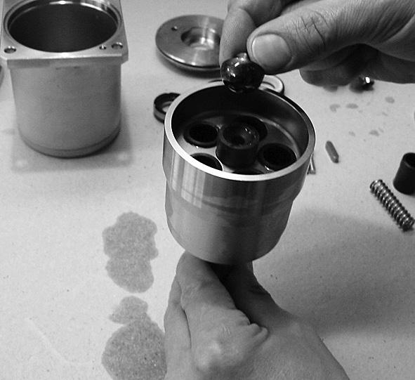
12 11. Mount the retainer guide on the spring guide. 12. Mount the retainer plate on the retainer guide. Ensure that the bended surface points downwards. 13. Insert the pistons. 14. All pistons inserted. 15. Place pin and place swash plate fittet on guide pin and center hole. 12


13 16. Place the screw in the center hole. 17. Tighten to a torque of 10 ±1 Nm. 18. Mount the pump housing using the pin as guide. 19. Press the housing down by hand and insert the screws. Alignment hole Guide pin 20. Tighten the screws to a torque of 22 Nm. 21. Mount the two O-rings in the flange and the O -ring on the front cover. 13


14 22. Wet the shaft seal with water and mount it in the front cover. Ensure that it is pressed to the bottom. 23. Mount the washer with the edge pointing upwards. 24. Mount the spring. 25. Fit the hollow bush onto the shaft. 26. Wet the shaft seal and slide it over the bush. 27. Use the shaft seal tool when pressing the shaft seal downwards. 14


15 28. Press the shaft seal in position. 29. Remove the bush. 30. Mount the front cover and align it to the screw holes. 31. Tighten the screws to a torque of 7 Nm. 15
16 4. Spare parts list for PAH / PAHT Pos. Qnt. Designation Material 180B Seal set (PAHT ) 180B Cylinder barrel set (PAHT ) 180B Cylinder barrel set (PAH ) 180B Valve plate set (PAHT ) 180B Piston set (PAHT ) 180B Piston set (PAH ) 180B Swash plate set (PAHT 10) 180B Swash plate set (PAHT 12.5) 1 1 Housing AISI 304 / PEEK 2 1 Pin Ø5 x 10 AISI 316 x 5 4 Screw M8 x 20 AISI 304 x 31 1 Swash plate AISI 431 x x 32 1 Screw M6 x 8 AISI 304 x x 33 1 Washer AISI 304 x x 34 1 Pin Ø5 x 10 AISI 316 x x 61 1 Cylinder barrel AISI 431 / PEEK x x 62 1 Spring AISI 316Ti x x 63 1 Spring guide PEEK x x 64 1 Retainer ball PEEK x x 65 1 Retainer plate AISI 304 x x 66 5 Piston AISI 431/ PEEK x x 67 1 Key 5 x 5 x 20 AISI 316Ti x 91 1 Port plate AISI 304 / PEEK x 92 1 Valve plate AISI 431 x 93 5 Back up ring PTFE x 94 5 O-ring Ø13 x Ø2 NBR x Port flange AISI 304 / PEEK O-ring Ø90 x Ø2 NBR x O-ring Ø75,92 x Ø1,78 NBR x Shaft seal AISI 304 / NBR x End cover AISI Pin Ø6 x 10 AISI Screw M5 x 20 AISI 304 x O-ring Ø7 x Ø1,5 NBR x 1 Service instruction x x x x x x x x 16
17 5. Exploded view PAH / PAHT
18 6. Spare parts list for PAHT G Pos. Qnt. Designation Material 180B Seal set (PAHT G ) 180B Cylinder barrel set (PAHT G ) 180B Valve plate set (PAHT G ) 180B Piston set (PAHT G ) 180B Swash plate set (PAHT G 10) 180B Swash plate set (PAHT G 12.5) 1 1 Housing AISI 304 / PEEK 2 1 Pin Ø5 x 10 AISI 316 x 5 4 Screw M8 x 20 AISI 304 x 31 1 Swash plate AISI 431 x x 32 1 Screw M6 x 8 AISI 304 x x 33 1 Washer AISI 304 x x 34 1 Pin Ø5 x 10 AISI 316 x x 61 1 Cylinder barrel AISI 431 / PEEK x 62 1 Spring AISI 316Ti x 63 1 Spring guide PEEK x 64 1 Retainer ball PEEK x 65 1 Retainer plate AISI 304 x 66 5 Piston AISI 431/ PEEK x 67 1 Key 5 x 5 x 20 AISI 316Ti x 91 1 Port plate AISI 304 / PEEK x 92 1 Valve plate AISI 431 x 93 5 Back up ring PTFE x 94 5 O-ring Ø13 x Ø2 NBR x Port flange AISI 304 / PEEK O-ring Ø90 x Ø2 NBR x O-ring Ø75,92 x Ø1,78 NBR x Shaft seal AISI 304 / NBR x End cover AISI Pin Ø6 x 10 AISI Screw M5 x 20 AISI 304 x O-ring Ø7 x Ø1,5 NBR x 1 Service instruction x x x x x x 18
19 7. Exploded view PAHT G
20 8. Tool sets Qnt. Designation 180Z Tool set (PAH / PAHT / PAHT G ) 1 Shaft bush, topedo x 1 Press bush Ø18 (Plastic) x Danfoss A/S High Pressure Pumps DK-6430 Nordborg Denmark Danfoss can accept no responsibility for possible errors in catalogues, brochures and other printed material. Danfoss reserves the right to alter its products without notice. This also applies to products already on order provided that such alterations can be made without subsequential changes being necessary in specifications already agreed. All trademarks in this material are property of the respective companies. Danfoss and the Danfoss logotype are trademarks of Danfoss A/S. All rights reserved. 20
PAH, PAHT, PAHT G pumps PAH , PAHT and PAHT G Disassembling and assembling
 Servie guide PAH, PAHT, PAHT G pumps PAH 10-12.5, PAHT 10-12.5 and PAHT G 10-12.5 Disassembling and assembling hpp.danfoss.com Table of Contents 1. Disassembling the pump...3 2. Inspection...7 2.1. Port
INSTRUCTIONS Servicing PAH
 INSTRUCTIONS Servicing PAH 10-12.5 180R9095 Note: Dismantling: If the pump is dismantled during the warranty period, the pump is no longer under warranty. 180R9095 1. Tools required for dismantling the
PAH pumps PAH Disassembling and assembling
 Service guide PAH pumps PAH 20-32 Disassembling and assembling hpp.danfoss.com Table of Contents 1. Disassembling the pump... 3 2. Inspection... 7 2.1. Port plate and thrust plate... 7 2.2. Pistons...
PAH pumps PAH Disassembling and assembling
 Service guide PAH pumps PAH 50-100 Disassembling and assembling hpp.danfoss.com Table of Contents 1. Disassembling the pump... 3 2. Inspection... 7 2.1. Port plate and thrust plate... 7 2.2. Pistons...
Changing pistons APP 21-43
 MAKING MODERN LIVING POSSIBLE Instruction Changing pistons APP 21-43 ro-solutions.com Contents 1. Disassembling...3 2. Assembling...6 3. When should the pistons be replaced....8 4. Parts list for APP 21-38....9
PAHT / PAHT G pumps PAHT / PAHT G Disassembling and assembling
 Service guide PAHT / PAHT G pumps PAHT 256-308 / PAHT G 256-308 Disassembling and assembling hpp.danfoss.com Table of Contents 1. Introduction... 2 2. Disassembling the pump... 3 3. Assembling the pump...
Changing pistons APP and APP 16-22
 MAKING MODERN LIVING POSSIBLE Instruction Changing pistons APP 11-13 and APP 16-22 ro-solutions.com Contents 1. Disassembling...3 2. Assembling...5 3. When should the pistons be replaced?....7 This document
Disassembling and assembling isave 21
 MAKING MODERN LIVING POSSIBLE Service instruction Disassembling and assembling isave 21 isave.danfoss.com Table of Contents 1. General introduction....2 2. Disassembling the isave....3 3. Disassembling
APP pumps APP(W) Disassembling and assembling
 Disassembling and assembling") Service guide APP pumps APP(W) 5.1-10.2 Disassembling and assembling hpp.danfoss.com Table of Contents Contents Introduction...2 1. Disassembling the pump...3 2. Assembling the pump...5 3. Disassembling
Service guide APP pumps APP(W) 5.1-10.2 Disassembling and assembling hpp.danfoss.com Table of Contents Contents Introduction...2 1. Disassembling the pump...3 2. Assembling the pump...5 3. Disassembling
INSTRUCTION. Internal pump elements APP6.5 - special 180B R R9134
 INSTRUCTION Internal pump elements APP6.5 - special 180B3101 180R9134 This document covers the instructions for changing internal pump elements on the axial piston pumps APP6.5. Note: It is essential that
Lenntech. Tel Fax
 Lenntech info@lenntech.com Tel. +31-152-610-900 www.lenntech.com Fax. +31-152-616-289 INSTRUCTION Internal pump elements APP5.1-10.2 180R9093 This document covers the instructions for changing internal
APP S pumps APP S / APP S / APP S 21-38
 MAKING MODERN LIVING POSSIBLE Instruction APP S 2.0-3.5 / APP S 5.1-9.0 / APP S 21-38 ro-solutions.com Instruction Table of Contents 1. Identification...2 2. System design...3 2.1 Open system design...3
Energy Recovery Device isave Disassembling and assembling
 Service guide Energy Recovery Device isave 50-70 Disassembling and assembling hpp.danfoss.com Table of Contents Contents 1. Introduction... 2 2. Disconnect the isave from the electric motor... 3 3. Disassembling
Service instructions. Table of contents BMP S BMP NS
 Service instructions BMP 2.5-8.0 S BMP 3.4-8.0 NS Table of contents 1. Type identification... 2 1.1 Nameplate... 2 1.2 TType key... 2 2. Torques and lubricants... 3 3. Service tools... 4 3.1 Special tools...
PAHT pump PAHT X
 MAKING MODERN LIVING POSSIBLE Data sheet PAHT pump PAHT X 674 444 danfoss.high-pressurepumps.com Table of Contents 1. Introduction...3 2. Benefits...3 3. Application areas...3 4. Technical data...4 5.
Vane pump upgrade kit 180F4161 isave 21 ERD Disassembling and assembling
 Service guide Vane pump upgrade kit 180F4161 isave 21 ERD Disassembling and assembling hpp.danfoss.com Table of Contents Contents 1. General Introduction...2 1.1 Parts included in the vane pump upgrade
2/4/6.3, PAH 10/12.5, PAH 50/63/70/80/100 pumps
 Data sheet PAH pumps 2/4/6.3, PAH 10/12.5, PAH 2/4/6.3, PAH 10/12.5, PAH 20/25/32 and and PAH 50/63/70/80/100 PAH 50/63/70/80/100 pumps danfoss.high-pressurepumps.com hpp.danfoss.com Table of Contents
ATEX instruction for APP / PAH PAHT G 2-90 / PAH Tech
 MAKING MODERN LIVING POSSIBLE Instruction ATEX instruction for APP 0.6-10.2 / PAH 2-100 PAHT G 2-90 / PAH 25-80 Tech danfoss.high-pressurepumps.com Table of Contents 1. Common demands for Category 2 and
Data sheet APP
 MAKING MODERN LIVING POSSIBLE Data sheet Data sheet APP 0.6-1.0 ro-solutions.com Table of Contents 1. General information....2 2. Benefits...3 3. Technical data...3 4. Flow at different rpm....4 5. Flushing
PAHT pumps / PAHT G pumps / ATEX PAHT G pump
 Lenntech info@lenntech.com Tel. +31-152-610-900 www.lenntech.com Fax. +31-152-616-289 Data sheet PAHT 2-308 pumps / PAHT G 2-308 pumps / ATEX PAHT G pump danfoss.high-pressurepumps.com Table of Contents
MAKING MODERN LIVING POSSIBLE. Data sheet. Data sheet APP ro-solutions.com
 MAKING MODERN LIVING POSSIBLE ro-solutions.com Table of Contents 1. General information..................................................................... Benefits................................................................................
APP pump instruction APP and APP 16-22
 MAKING MODERN LIVING POSSIBLE Instruction APP pump instruction APP 11-13 and APP 16-22 www.ro-solutions.com Table of Contents 1. Identification...2 2. System design...3 2.1 Open-ended systems with direct
MAKING MODERN LIVING POSSIBLE. Data sheet. Data sheet APP ro-solutions.com
 MAKING MODERN LIVING POSSIBLE Data sheet Data sheet APP 11-13 ro-solutions.com Table of Contents 1. Introduction...3 2. Benefits...3 3. Technical data...4 4. Variants...4 5. Flow at different rpm....5
APP pump instruction APP 21-43
 MAKING MODERN LIVING POSSIBLE Instruction APP pump instruction APP 21-43 ro-solutions.com Table of Contents 1. Identification...2 2. System design...3 2.1 Open-ended systems with direct water supply....3
Steering Unit Type OSPB and OSPC Type ON and CN
 MAKING MODERN LIVING POSSIBLE Service Manual Steering Unit Type OSPB and OSPC Type ON and CN powersolutions.danfoss.com Revision History Table of Revisions Date Changed Rev Mar 2014 Converted to Danfoss
PAH / PAHT / PAHT G pumps
 Lenntech info@lenntech.com Tel. +31-152-610-900 www.lenntech.com Fax. +31-152-616-289 Instruction PAH / PAHT / PAHT G 10-12.5 pumps Instruction Pump instruction PAH / PAHT / PAHT G 10-12.5 Table of Contents
MAKING MODERN LIVING POSSIBLE. Service Manual. Steering OSPM. powersolutions.danfoss.com
 MAKING MODERN LIVING POSSIBLE Service Manual Steering OSPM powersolutions.danfoss.com Revision History Table of Revisions Date Changed Rev Mar 2014 Converted to Danfoss layout - DITA CMS BA Feb 1998 First
OMT Series 2. Orbital Motors. Service Manual
 OMT Series 2 Orbital Motors Table of Contens, Special Versions Revision History Table of Revisions Date Page Changed Rev Sept 2003 CA Feb 200 4-5 Drain plug updated, Layout adjusted CB Sep 200 6 New back
Solenoid valve VDHT Standard BSP (British Standard Pipe)
") MAKING MODERN LIVING POSSIBLE Data sheet Standard BSP (British Standard Pipe) high-pressurepumps.danfoss.com Contents 1. Picture overview...3 2. Introduction...4 3. VDHT valve selection overview...4 4.
MAKING MODERN LIVING POSSIBLE Data sheet Standard BSP (British Standard Pipe) high-pressurepumps.danfoss.com Contents 1. Picture overview...3 2. Introduction...4 3. VDHT valve selection overview...4 4.
APP S 674 pumps APP S / APP S APP S
 MAKING MODERN LIVING POSSIBLE Data sheet APP S 674 3.0-3.5 / APP S 674 5.1-9.0 APP S 674 21-38 ro-solutions.com Table of Contents 1. Introduction...3 2. Benefits...3 3. Application areas...3 4. Technical
MAKING MODERN LIVING POSSIBLE. Product overview. . Energy efficient. Reliable. Very long service intervals HIGH-PRESSURE SYSTEMS
 MAKING MODERN LIVING POSSIBLE Product overview. Energy efficient. Reliable. Very long service intervals HIGH-PRESSURE SYSTEMS Application examples: Fire fighting: Using high-pressure water mist for fire
Sub Section Title Page No.
 Sub Section Title Page No. 1 Introduction 3 2 Routine Maintenance 3 3 Disassembly 4 3.1 Disassembly of Double Crank Design 4 3.2 Disassembly of Scotch Yoke Design 5 3.3 Disassembly of Actuator Cylinder
Installation Instructions Bus Bar Kit for 6-pulse, 4-drive System VLT Series FC 102, FC 202, and FC 302. Description. Kit Part Number.
 Description The bus bar kit is designed for the specific VLT HVAC Drive FC 102, VLT AQUA Drive FC 202, and VLT AutomationDrive FC 302 D4h-size VLT Parallel Drive Modules mounted in a Rittal TS8 enclosure.
Steering Priority Valve OLS 160
 MAKING MODERN LIVING POSSIBLE Service Manual Steering Priority Valve OLS 160 powersolutions.danfoss.com Revision History Table of Revisions Date Changed Rev Mar 2014 Converted to Danfoss layout - DITA
Integrated Presetting Valves for Normal (013G0380) and Small (013G0381) Volume Flows
 and Small (013G0381) Volume Flows") Integrated Presetting Valves for Normal (013G0380) and Small (013G0381) Volume Flows Application Integrated valves, type RA-N (013G0380) and RA- U (013G0381), with built-in presetting are designed for
Integrated Presetting Valves for Normal (013G0380) and Small (013G0381) Volume Flows Application Integrated valves, type RA-N (013G0380) and RA- U (013G0381), with built-in presetting are designed for
Hydrostatic Steering Unit Type OSPB, OSPC and OSPF. Service Manual
 Hydrostatic Steering Unit Type OSPB, OSPC and OSPF Table of Contens Revision History Table of Revisions Date Page Changed Rev Dec 2008 26 Tightening torque changed BC Table of contens... 2 Exploded view
OMR, OMR C, and OMRW N Series 5 and 6. Repair Instructions
 , C, and W N Series and Orbital Motors, C and W N Series and Table of Contents Revision View Safety Precautions Date Page Changed Revision 29 Jun, 200 all Changed from Danfoss to Sauer Danfoss lay out
Tel: +44 (0) E mail: Web: Data sheet. APP pumps APP ro-solutions.com
 E mail: Web: Data sheet. APP pumps APP ro-solutions.com") APP pumps APP 53-78 Tel: +44 (0) 1706 869777 E mail: sales@desal.co.uk Web: www.desal.co.uk ro-solutions.com Table of Contents 1. Introduction...3 2. Benefits...3 3. Application examples...3 4 Technical
APP pumps APP 53-78 Tel: +44 (0) 1706 869777 E mail: sales@desal.co.uk Web: www.desal.co.uk ro-solutions.com Table of Contents 1. Introduction...3 2. Benefits...3 3. Application examples...3 4 Technical
Control Card VLT FC Series
 These instructions describe the replacement of the control card in: VLT HVAC Drive FC 102. VLT Refrigeration Drive FC 103. VLT AQUA Drive FC 202. VLT AutomationDrive FC 301/FC 302. VLT Lift Drive LD 302.
OMP, OMP C, OMPW, and OMPW N Series 7 and 8. Repair Instructions
 , C, W, and W N Series and 8 Orbital Motors, C, and W/N Series and 8 Table of Contents Revision View Safety Precautions Date Page Changed Revision 29 Jun, 200 all Changed from Danfoss to Sauer Danfoss
OMH. Repair Instructions
 OMH Table of Contents Revision View Date Page Changed Revision Jun 2006 New AA Apr 200 6 Japan location AB Sep 200 6 New back cover AC Safety Precautions Always consider safety precautions before beginning
Integrated Presetting Valves - for Normal Volume Flows RA-N and for Small Volume Flows RA-U
 Integrated Presetting Valves - for Normal Volume Flows RA-N and for Small Volume Flows Application RA-N 013G7382 013G7387 Integrated valves, type RA-N 013G7382 and 013G7387, with built-in presetting are
Installation Instructions In-bottom/Out-back Cooling Kit for E4h Drives VLT FC Series FC 102, FC 103, FC 202, and FC 302
 1.1 Description The in-bottom/out-back cooling kit fits the following E4h drives. It is compatible with drives mounted in Rittal TS8 800 mm (32 in) cabinets. VLT HVAC Drive FC 102 VLT Refrigeration Drive
3/2-Way Zone-Drain-Valves VDHT 2E, VDHT 15E and VDHT 15EC
 Lenntech info@lenntech.com Tel. +31-152-610-900 www.lenntech.com Fax. +31-152-616-289 3/2-Way Zone-Drain-Valves VDHT 2E, VDHT 15E and VDHT 15EC danfoss.high-pressurepumps.com General information The 3/2
Integrated Valve with Presetting for Manifolds in Two-Pipe Heating Systems
 Data Sheet Integrated Valve with Presetting for Manifolds in Two-Pipe Heating Systems The integrated valve is designed for manifold applications in combination with a system connection piece. Valve and
Series 20 Axial Piston Pumps. Technical Information
 Series 20 Axial Piston Pumps Technical Information General Description INTRODUCTION Sauer-Danfoss a world leader in hydraulic power systems has developed a family of axial piston pumps. DESCRIPTION Sauer-Danfoss
Series 20 Axial Piston Pumps. Technical Information
 Series 20 Axial Piston Pumps Technical Information General Description INTRODUCTION Sauer-Danfoss a world leader in hydraulic power systems has developed a family of axial piston pumps. DESCRIPTION Sauer-Danfoss
Steering Valve EHPS and EHPS with OLS 320
 Service Manual Steering Valve EHPS and EHPS with OLS 320 powersolutions.danfoss.com Revision history Table of revisions Date Changed Rev July 2016 Updated EHPS spare parts list 0102 June 2015 First version
APP pumps APP / APP / APP / APP (W) / APP / APP / APP 21-43
 / APP / APP / APP 21-43") Data sheet Data sheet APP Pumps APP 0.6-1.0 / APP 1.5-3.5 / APP (W) 5.1-10.2 / APP 11-13 / APP pumps APP 16-22 0.6-1.0 / APP / 21-43 APP 1.5-3.5 / APP (W) 5.1-10.2 / APP 11-13 / APP 16-22 / APP 21-43 ro-solutions.com.
Data sheet Data sheet APP Pumps APP 0.6-1.0 / APP 1.5-3.5 / APP (W) 5.1-10.2 / APP 11-13 / APP pumps APP 16-22 0.6-1.0 / APP / 21-43 APP 1.5-3.5 / APP (W) 5.1-10.2 / APP 11-13 / APP 16-22 / APP 21-43 ro-solutions.com.
FRP Ball Valves INSTALLATION & MAINTENANCE MANUAL
 FRP Ball Valves INSTALLATION & MAINTENANCE MANUAL FRP BALL VALVES TABLE OF CONTENTS MAINTENANCE AND INSTALLATION INSTRUCTIONS 1. 2. 2.1 2.2 2.3 2.4 GENERAL...Page 1 HANDLING...1 Receiving and Storing...1
Nessie High-Pressure Pumps for technical water, type PAH
 Data Sheet Nessie High-Pressure Pumps for technical water, type PAH Generally The Danfoss Nessie high-pressure water pumps are especially designed for operation on technical water, such as reverse osmosis-,
ATEX instruction APP S 674 pumps APP S , APP S and APP S
 MAKING MODERN LIVING POSSIBLE Instruction APP S 674 2.0-3.5, APP S 674 5.1-9.0 and APP S 674 21-38 ro-solutions.com Table of Contents 1. General information....2 2. Common demands for Category 2 and 3
Installation Guide. DEVIreg 527. Electronic Time Regulator.
 DEVIreg 527 Electronic Time Regulator www.devi.com Table of Contents DEVIreg 527 1 Introduction..................... 2 1.1 Technical Specifications........... 3 1.2 Safety Instructions............... 4
Jr. T GENERAL. BAM: Bomber Aerospace Material. Special alloy extracted from aerospace material. Ø TRAVEL ±
 175 15 GENERAL The double clamp fork is specifically designed for Downhill use. The fork is sprung by a mechanical spring and uses hydraulic rebound damping. Spring pre-load adjustment controlled via external
Installation Instructions 500 A Current Sensor Kit for F1 F4/F8 F13 Enclosure Sizes VLT Series FC 102, FC 202, and FC 302
 1.1 Description The 500 A current sensor kit is designed for F1 F4 and F8 F13 enclosure sizes in the power ranges shown in Table 1.1. To identify the power rating, see Illustration 1.1. Product group and
Installation Guide. VLT Real-time Clock MCB 117 VLT HVAC Drive FC 102, VLT Refrigeration Drive FC 103, VLT AQUA Drive FC 202, VLT AutomationDrive
 Installation Guide VLT Real-time Clock MCB 117 VLT HVAC Drive FC 102, VLT Refrigeration Drive FC 103, VLT AQUA Drive FC 202, VLT AutomationDrive FC 301/FC 302 Installation Guide VLT Real-time Clock MCB
Service instructions. Contents. MTR 10, 15 and /60 Hz 1/3~
 Service instructions MTR 0, and 0 0/0 Hz /~ Contents. Type identification.... Nameplate.... Type key.... Code for shaft seal.... Torques and lubricants.... Service tools.... Special tools.... Standard
4357 / 4860 MX Multi Adjuster
 12_234 Frontfork 4357 / 4860 MX Multi Adjuster Introduction 2 Exploded view 3 Disassembly forkleg 4 Disassembly screw-cap 15 Assembling screw-cap 17 Disassembly cartridge 18 Disassembly compression holder
Quick Reference Parts Manual Variable Displacement Motor Series 20, series powersolutions.danfoss.com
 MAKING MODERN LIVING POSSIBLE Quick Reference Parts Manual Variable Displacement Motor Series 20, 20-27 series powersolutions.danfoss.com 2 Contents Service parts Exploded view drawing (20 thru 23 series)...4
OML and OMM Orbital Motors. Repair Instructions
 OML and OMM Orbital Motors Table of Contents, Revision View and Safety Precautions Revision View Date Page Changed Revision Jan 2008 all Changed from Danfoss to Sauer Danfoss lay out AA Mar 2008 13 Service
Instruction Manual. SMP-BCA Aseptic Mixproof Valve with PTFE Diaphragm IM70811-EN
 Instruction Manual SMP-BCA Aseptic Mixproof Valve with PTFE Diaphragm IM70811-EN3 2010-04 Declaration of Conformity The designating company Alfa Laval Company Name Albuen 31, DK-6000 Kolding, Denmark
Operating Guide SBFV (PN16/25) ENGLISH Steel butterfly valve SBFV Page 2. Danfoss VI.IX.A1.02 1
 ENGLISH Steel butterfly valve SBFV Page 2. Danfoss VI.IX.A1.02 1") Operating Guide SBFV (PN16/25) ENGLISH Steel butterfly valve SBFV www.danfoss.com Page 2 Danfoss 2016.06 VI.IX.A1.02 1 Table of Contents: 1. OVERVIEW... 3 2. GENERAL... 3 2.1 Safety...3 2.2 Proper use...4
Operating Guide SBFV (PN16/25) ENGLISH Steel butterfly valve SBFV www.danfoss.com Page 2 Danfoss 2016.06 VI.IX.A1.02 1 Table of Contents: 1. OVERVIEW... 3 2. GENERAL... 3 2.1 Safety...3 2.2 Proper use...4
Maverick American 3085 Bluff Street Boulder, CO Tel: Fax: ML7.0 SHOCK SERVICE MANUAL
 Maverick American 3085 Bluff Street Boulder, CO 80301 Tel: 303-415-0370 Fax: 303-415-0676 www.maverickamerican.com ML7.0 SHOCK SERVICE MANUAL 1. OVERVIEW 1.1. The Maverick ML7.0 rear shock is an oil damped
Unique 7000 Series Valve - Standard and Reverse Acting
 Instruction Manual Unique 7000 Series Valve - Standard and Reverse Acting ESE00213-ENUS4 2012-01 Original manual Table of contents The information herein is correct at the time of issue but may be subject
Butterfly valve with electrical actuator VFY-WA
 Butterfly valve with electrical actuator Description Position indicator Torque limiter Complete installation from factory - ready for installation Features: Spline driven one piece shaft connected to spherically
Butterfly valve with electrical actuator VFY-WA
 Butterfly valve with electrical actuator Description Position indicator Torque limiter Complete installation from factory - ready for installation Features: Spline driven one piece shaft connected to spherically
Maintenance Information
 16605958 Edition 2 May 2014 Air Percussive Rivet Buster Models 9001 and 11001 Maintenance Information Save These Instructions Product Safety Information WARNING Failure to observe the following warnings,
Guides, Brakes and Valves
 Guides, Brakes and Valves Operating Instructions ORIGA SYSTEM PLUS Appendix to the Operating Instructions OSP-P / OSP-E Guides, Brakes and Valves OSP-P / OSP-E Content 1 Foreword to the Operating Instructions
Installation Instructions In-back/Out-back Cooling Kit for D5h/D6h and D7h/D8h Enclosures VLT Series FC 102, FC 202, and FC 302
 In-back/Out-back Cooling Kit for D5h/D6h and D7h/D8h Enclosures VLT Series FC 102, FC 202, 1.1 Description Base plate assembly The back-channel cooling (in-back/out-back) kit is designed for the D5h/D6h
Z1 Free Ride INSTRUCTIONS GENERAL RULES
 INSTRUCTIONS GENERAL RULES 1. Where specified, assemble and disassemble the shock absorption system using the MARZOCCHI special tools only, as shown in the table below. 2. On reassembling the suspension
3.2 DRIVE TORQUE HUB. Roll, Leak and Brake Testing SECTION 3 - CHASSIS & TURNTABLE. 3-2 JLG Lift
 3.2 DRIVE TORQUE HUB Roll, Leak and Brake Testing 10 LUG PATTERN Torque-Hub units should always be roll and leak tested before disassembly and after assembly to make sure that the unit's gears, bearings
Features. Marathon SL TECHNICAL CHARACTERISTICS. Sliding bushes: made of friction free and wear free material.
 Features TECHNICAL CHARACTERISTICS Fork with Ø30 mm legs with "Double Air" damping system. Adjustment of the air preload (positive air) on both legs. Adjustment of the rebound damping (negative air) on
Super T QR20 INSTRUCTIONS GENERAL RULES
 INSTRUCTIONS GENERAL RULES 1. Where specified, assemble and disassemble the shock absorption system using the MARZOCCHI special tools only. 2. On reassembling the suspension system, always use new seals.
Sachs shock manual. ( ) 2 & 4 Stroke RR Enduro. ( ) RS Dual Sport
 2 & 4 Stroke RR Enduro. ( ) RS Dual Sport") Sachs shock manual (2013 2015) 2 & 4 Stroke RR Enduro (2014-2015) RS Dual Sport 1 Introduction The procedures in this manual must take place in a clean environment using professional tools and some specific,
Sachs shock manual (2013 2015) 2 & 4 Stroke RR Enduro (2014-2015) RS Dual Sport 1 Introduction The procedures in this manual must take place in a clean environment using professional tools and some specific,
APP pumps APP / APP / APP (W) / APP / APP / APP Lenntech. Data sheet
 / APP / APP / APP Lenntech. Data sheet") MAKING MODERN LIVING POSSIBLE Lenntech info@lenntech.com Tel. +31-152-610-900 www.lenntech.com Fax. +31-152-616-289 Data sheet APP pumps APP 0.6-1.0 / APP 1.5-3.5 / APP (W) 5.1-10.2 / APP 11-13 / APP 16-22
MAKING MODERN LIVING POSSIBLE Lenntech info@lenntech.com Tel. +31-152-610-900 www.lenntech.com Fax. +31-152-616-289 Data sheet APP pumps APP 0.6-1.0 / APP 1.5-3.5 / APP (W) 5.1-10.2 / APP 11-13 / APP 16-22
Servo-operated 2/2-way solenoid valves with isolating diaphragm Type EV222B
 Data sheet Servo-operated 2/2-way solenoid valves with isolating diaphragm Type EV222B EV222B is an indirect servo-operated solenoid valve programme for use in connection with contaminated or aggressive
Overhaul Special Tools Required
 1 of 31 Overhaul - Special Tools Required - Cylinder end seal remover attachment, 07NAD-SR3020A - Pilot collar, 07GAF-PH70100 - Valve seal ring sizing tool, 07NAG-SR3090A - Ball joint boot clip guide,
Disassembling and Assembling
 Disassembling and Assembling How to disassemble and assemble the controller box 1. Disassembling of controller box Phillips screwdriver, 8# wrench, scissors or penknife. 1) First dismantle the rear bottom
Instruction Manual. SMP-BC Sanitary Mixproof Valve IIM70771-GB
 Instruction Manual SMP-BC Sanitary Mixproof Valve IIM70771-GB3 1996-03 Declaration of Conformity The designating company Alfa Laval Company Name 6000 Kolding Address +45 79 32 22 00 Phone No. hereby declare
Service Handbook High-Pressure Washer Pump
 Service Handbook High-Pressure Washer Pump 9.120-014.0 2 A. Water Inlet Filter C. Nozzle Insert 1. Remove filter with a screwdriver. 2. Clean filter with warm water and mild soap. 3. Reinstall filter.
IOM-CleanFLOW TM. CleanFLOW Series Ball Valves. SV F Flow Controls I N C O R P O R A T E D
 !!!CAUTION! Safety Precautions!!! Before removing valve from pipeline NOTE that: Media flowing through a valve may be corrosive, toxic, flammable, a contaminant or harmful nature. Where there is evidence
1. introduction 3 2. Wheel bearing special features 4 3. Wheel bearing units from an economical point of view 5
 Motor chassis Service Technical BROCHuRE Wheel Bearing Repair Solutions for Light Commercial Vehicles CONTENT 1. introduction 3 2. Wheel bearing special features 4 3. Wheel bearing units from an economical
MAKING MODERN LIVING POSSIBLE. UniLynx Indoor Installation Manual. ULX 1800i ULX 3000i ULX 3600i ULX 5400i SOLAR INVERTERS
 MAKING MODERN LIVING POSSIBLE UniLynx Indoor Installation Manual ULX 1800i ULX 3000i ULX 3600i ULX 5400i SOLAR INVERTERS Contents Contents 1. Introduction 2 Introduction 2 Installation Sequence 2 Important
ZE ZE ZE. Simplex expanding wedge brake Assembly and Maintenance Instructions
 Simplex expanding wedge brake Assembly and Maintenance Instructions Simplex expanding wedge brake Assembly and Maintenance Instructions Edition 1 This publication is not subject to any update service.
CHESTERTON FLOW GUARDIAN S50 AND SP50 SINGLE FLOWMETER INSTALLATION INSTRUCTIONS
 INSTALLATION INSTRUCTIONS CHESTERTON FLOW GUARDIAN S50 AND SP50 SINGLE FLOWMETER INSTALLATION INSTRUCTIONS GENERAL The function of the FLOW GUARDIAN Single S50 (Item # 199801 compression fitting, 199804
Workshop manual 5018 PDS Product Exploded View Disassembly & Assembling. Shock absorber 5018 PDS OEM Shock absorber 5018 PDS /2002
 Shock absorber 5018 PDS OEM 2000 Introduction 2 Exploded view 3 Disassembly shock absorber 4 Disassembly piston-rod 11 Disassembly adaptor DU-bush 15 Assembling adaptor DU-bush 17 Assembling piston-rod
Installation Instructions 500 A Current Sensor Kit for D2h/D4h/D7h/D8h Enclosure Sizes VLT Series FC 102, FC 103, FC 202, and FC 302
 Description The 500 A current sensor kit is designed for D2h/D4h/D7h/D8h enclosure sizes in the power ranges shown in Table 1.1. To identify the power rating, see Illustration 1.1. Product group and drive
Installation Instructions 300 A Current Sensor Kit for D1h/D3h/D5h/D6h Enclosure Sizes VLT Series FC 102, FC 103, FC 202, and FC 302
 1.1 Description The 300 A current sensor kit is designed for D1h/D3h/D5h/D6h enclosure sizes in the power ranges shown in Table 1.1. To identify the power rating, see Illustration 1.1. Product group and
Z5 Coil (80) GENERAL. BAM: Bomber Aerospace Material. Special alloy developed from aerospace material. Ø TRAVEL 80 55
 GENERAL. BAM: Bomber Aerospace Material. Special alloy developed from aerospace material. Ø TRAVEL 80 55") (8) 175 8 Ø3 +.5 L.MAX=461 L.L.=451 L.MIN=371 ±2 396 ±2 TRAVEL 8 55 18 Ø3 15 2 -.1 +1 248.5 GENERAL The fork is sprung by a mechanical coil system and uses hydraulic rebound damping. Spring pre-load adjustment
(8) 175 8 Ø3 +.5 L.MAX=461 L.L.=451 L.MIN=371 ±2 396 ±2 TRAVEL 8 55 18 Ø3 15 2 -.1 +1 248.5 GENERAL The fork is sprung by a mechanical coil system and uses hydraulic rebound damping. Spring pre-load adjustment
Pressure relief controller AVA (PN 25)
") Data sheet Pressure relief controller AVA (PN 25) Description AVA is a self-acting pressure relief controller primarily for use in district heating systems. The controller is normally closed and opens
Data sheet Pressure relief controller AVA (PN 25) Description AVA is a self-acting pressure relief controller primarily for use in district heating systems. The controller is normally closed and opens
Disassembly. 1 Pull off the QUIK-LOK cable from the machine.
 Special Tools Require Important! Torx TX0 bit 0 0 Screwdriver Torx 0 0 0 Forcing Discs 0 Before beginning the maintenance work, perform an initial check with a high voltage test according to VDE (see chapter
ORIGA SYSTEM PLUS Guides, Brakes and Valves for Modular Linear Drive Systems OSP Appendix to the Operating Instructions
 ORIGA SYSTEM PLUS Guides, Brakes and Valves for Modular Linear Drive Systems OSP Appendix to the Operating Instructions TAll personnel who have anything to do with the OSP fitted with guides, brakes or
X-FLY (80) GENERAL. BAM: Bomber Aerospace Material. Special alloy developed from aerospace material. Ø TRAVEL Ø30
 GENERAL. BAM: Bomber Aerospace Material. Special alloy developed from aerospace material. Ø TRAVEL Ø30") (8) 175 8 Ø3 +.5 L.MAX=461 L.L.=451 L.MIN=371 ±2 396 ±2 TRAVEL 8 55 18 Ø3 15 2 -.1 +1 248.5 GENERAL Special air/oil damped cross-country fork: each leg uses pressurized air blown through a special valve
(8) 175 8 Ø3 +.5 L.MAX=461 L.L.=451 L.MIN=371 ±2 396 ±2 TRAVEL 8 55 18 Ø3 15 2 -.1 +1 248.5 GENERAL Special air/oil damped cross-country fork: each leg uses pressurized air blown through a special valve
FLOWSERVE CORPORATION NOBLE ALLOY VALVE BALL VALVE REPAIR INSTRUCTION
 FLOWSERVE CORPORATION NOBLE ALLOY VALVE BALL VALVE REPAIR INSTRUCTION Cookeville Valve Operation 1978 Foreman Drive Cookeville, TN 38541 PH: 800-251-6761 931-432-4021 FAX: 931-432-5518 CONTENTS FLOWSERVE/NOBLE
Workshop manual 3612 / 4681 BAVP. Product Exploded View Disassembly & Assembling. Shock absorber
 455 Shock absorber 3612/4681 BAVP 02/2002 Shock absorber Introduction 2 Exploded view 3 Adjustment 4 Disassembly shock absorber 5 Disassembly piston-rod 7 Disassembly adaptor DU-bush 15 Disassembly tube
Series TMM Axial Piston Motor. Technical Information
 Series TMM Axial Piston Motor Technical Information General Description GENERAL DESCRIPTION These motors are designed primarily to be combined with other products in closed circuit systems to transfer
Duct System for Danfoss Air Units
 MAKING MODERN LIVING POSSIBLE Installation Guide for Danfoss Air Units www.heating.danfoss.com Danfoss A/S is not liable or bound by warranty if these instructions are not adhered to during installation
PAN 17 MECHANICAL SLIDING CALLIPER DISC BRAKE ASSEMBLY AND MAINTENANCE INSTRUCTIONS
 PAN 17 MECHANICAL SLIDING CALLIPER DISC BRAKE ASSEMBLY AND MAINTENANCE INSTRUCTIONS PAN 17 MECHANICAL SLIDING CALLIPER DISC BRAKE Assembly and Maintenance Instructions 2nd edition This publication is
Z3 Air (80) GENERAL. BAM: Bomber Aerospace Material. Special alloy developed from aerospace material. Ø TRAVEL 80 L.MAX=461 L.L.=451 L.
 GENERAL. BAM: Bomber Aerospace Material. Special alloy developed from aerospace material. Ø TRAVEL 80 L.MAX=461 L.L.=451 L.") (80) 175 18 80 Ø30 +0.05 0 55 L.MAX=461 L.L.=451 L.MIN=371 396 ±0,1 TRAVEL 80 ±2 Ø30 15 20 0-0.1 +1 0 248 GENERAL Special air/oil damped cross-country fork: each leg uses pressurized air blown through
(80) 175 18 80 Ø30 +0.05 0 55 L.MAX=461 L.L.=451 L.MIN=371 396 ±0,1 TRAVEL 80 ±2 Ø30 15 20 0-0.1 +1 0 248 GENERAL Special air/oil damped cross-country fork: each leg uses pressurized air blown through
Marzocchi Suspension MZ I MZ I. Technical instructions
 Technical instructions Exploded view - MZ I - 100 Rif. Code Quantity Spare part list - MZ I - 100 Rif. Code Description Q.ty in the model Technical characteristics: Technical characteristics Single-crown