Maverick American 3085 Bluff Street Boulder, CO Tel: Fax: ML7.0 SHOCK SERVICE MANUAL
|
|
|
- Cameron Poole
- 5 years ago
- Views:
Transcription

1 Maverick American 3085 Bluff Street Boulder, CO Tel: Fax: ML7.0 SHOCK SERVICE MANUAL
2 1. OVERVIEW 1.1. The Maverick ML7.0 rear shock is an oil damped system with internal coil spring with air spring assist. It has external rebound and air pressure adjustments. In Addition, the internal coil spring and rebound valving can be changed internally The shock is built similar to a front fork, with two telescoping tubes and a bushing designed to take heavy side loads. The outer telescoping tube is rigidly mounted to the rear frame triangle to increase stiffness and securely hold the shock. The shock also plays an important roll in creating the linear wheel path, which is the cornerstone of the Monolink system The damping system is a relatively simple unit, and is entirely housed within the inner tube of the shock. It can be quickly removed for service of the damper unit itself, or cleaning of the Wiper and Main Seal. In almost every service procedure, the outer Shock Body can be left in place, remaining attached to the frame. 2
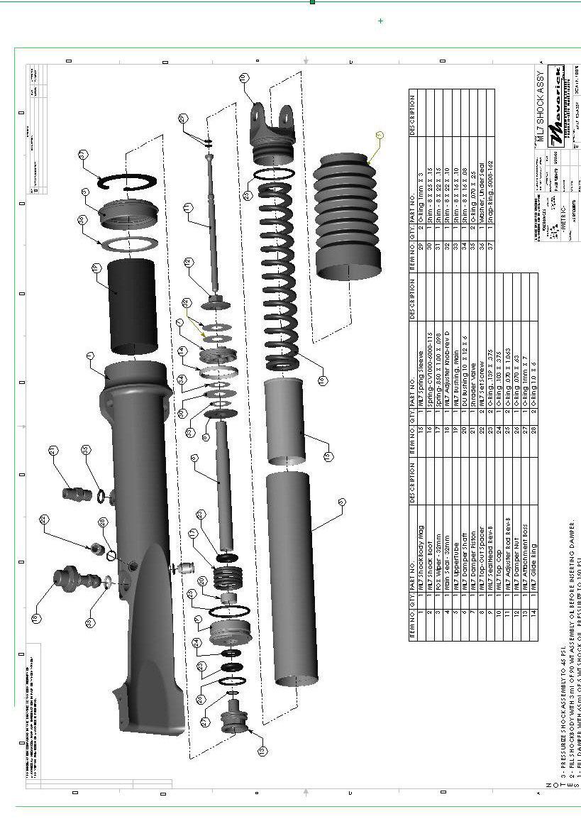
3 2. DESCRIPTION OF FUNCTIONS AND EXPLODED VIEWS (See Page 4 for Exploded Views and Parts List) 2.1. DAMPER: The damper assembly, all contained within the Inner Tube, contains a 5 wt shock oil and a small charge of air pressure. The Damper Shaft at the bottom end is threadably fixed to the Attachment Boss, which holds the Damper to the Shock Body. The Damper Shaft passes through the Seal Head and holds the Damper Piston assembly at its top end. The Damper Piston has Valve Shims clamped to its upper and lower faces to create separate rebound and compression damping rates. The Damper Nut holding the Piston to the Damper Shaft has a flange that rests against the internal Main Spring (coil) and acts to compress the spring when the shock is compressed. The Damper Unit contains 5-wt shock oil that the piston passes through when the shock is moving. When the shock is compressed or extended, the corresponding Valve Shim is forced open by the oil pressure to create the appropriate damping effect. Oil may also pass through the center of the shaft and out a side hole in the Damper Shaft. The amount of oil that may pass through the hole, and bypass s the Piston Valves, is altered by the Adjuster Rod that runs down the center of the Damper Shaft and is moved by the Adjuster Knob. The air charge is to allow for the volume the shaft will displace when it is pushed into the Damper Unit. As the shaft is pushed in, the air is further compressed. The air is pressurized so oil will pass through the Damper Piston instead of compressing that air, causing a loss of damping. 3
4 4
 Locktite 3.9. 5wt Fork Oil 3.10. Access to a Flat Jawed Vice and Work Stand 5")
5 3. REQUIRED TOOLS AND/OR EQUIPMENT (Show pic of tools) 3.1. One Maverick Suspension Tool Kit 3.2. One Shock Pump 3.3. Two 5mm Hex Keys 3.4. One Flat Head Screwdriver 3.5. One Pair of Snap Ring Pliers 3.6. One 10mm Wrench 3.7. One 26mm Socket and Wrench 3.8. Medium Strength (Blue) Locktite wt Fork Oil Access to a Flat Jawed Vice and Work Stand 5
.")
6 4. SERVICE PROCEDURES 4.1. Removing shock from frame Wash the bike. (You ll thank us later) Release the air pressure from the shock through the Schrader Valve (very important!). Pull the Adjuster Knob out of the Shock Body by pulling and twisting at the same time Remove the Top Shock Bolt using two 5mm hex keys. 6


7 Loosen the Set Screws two turns using a 5mm Hex key Rotate the bike in the stand so the shock is horizontal (this will prevent the lubrication oil from running out of the Adjuster Knob hole). Now grasp the Top Cap and pull the Inner Tube out of the Shock Body. 7


8 To re-install, position the bike so the Shock Body is horizontal, add 2ml of Maverick Gunna-Flow lube into the Shock Body. Smear another 1ml of lube to the Wiper, Main Seal and Bushing Slide the Damper Unit into the Shock Body and past the Wiper and Seal. The damper will need to be wobbled and rotated to ensure that the Wiper is not damaged or the sealing lips are not inverted. 8


9 The Damper Unit should be pushed in as far as possible to seat the Attachment Boss into the bore at the Bottom of the Shock Body. Now tighten the Set Screws. The outside edge of the Set Screws should tighten flush against the outside of the Shock Body. If they tighten at a point above or below that, then the Attachment Boss is not seated correctly. Remove one of the Set Screws and look in the hole to see if the groove of the Attachment Boss is level with the center of the Set Screw hole. If it is not, push the Damper Unit further in Install the Adjuster Knob and pressurize the shock the appropriate amount. 9
10 Install the Top Shock Bolt The Shock should be ready to ride!!!! 10


11 4.2. Cleaning the Wiper and Main Seal Remove the Damper from the Shock Body (as detailed in Section 4.1) Use a clean, lint-free rag to wipe out the Wiper, Main Seal and Bushing. The lubrication oil should also be cleaned out of the entire Shock Body. Be sure to thoroughly clean any dirt or grime out of the sealing lips of the wiper and Main Seal It is HIGHLY recommended to replace the wiper with the more current model used in the 7.2 shock and Maverick DUC32 fork. It has far superior sealing capabilities. NOTE: If the shock was loosing air pressure, it was most likely caused by dirt in the lips of the Main Seal. It should not be necessary to replace the Main seal. Rarely does one wear out and it is far more likely to damage the seal or Shock Body during replacement Re-install the Damper unit as detailed in Section Bushing replacement Remove the Inner Tube Assembly from the Shock Body as Detailed in Section Gently pry the Wiper out of the Shock Body by twisting the tip of a small screwdriver between the Shock Body and Wiper s flange. 11


12 Remove the Snap Ring that holds the Main Seal in Place, and carefully pry the Main Seal out of the Shock Body using a large screwdriver. This will destroy the Main Seal and it will need to be replaced. The tip of the screwdriver should be positioned just under the lip and within the outer ring of the seal. DO NOT ALLOW THE SCREWDRIVER TIP TO SCRATCH THE SEAL BORE OF THE SHOCK BODY WHEN PRYING IT OUT OR YOU MIGHT CREATE A LEAK PATH THAT CAN T BE FIXED! Remove the Seal Washer. 12


13 The bushing can now be pulled from the Shock Body using the Maverick Bushing Tool. This can usually be done while the Shock Body is still in the frame. Insert the split end of the Bushing Tool through the Bushing. Tighten the nut on the end of the Tool snug, but not tight. Pull the bushing out of the Shock Body. If the bushing is too tight to remove while the Shock Body is in the frame, remove it and clamp the Bushing Tool into a vice. Use a vice with soft V shaped jaws. Be careful not to damage the bulged end of the tool in the vice Install the new Bushing by pushing it into the Shock Body by hand. Install the Seal Washer, Main Seal, Snap Ring (sharp edge facing up) and Wiper. The bore and seals should be lightly greased beforehand. BE SURE THE SEAL IS FACING THE CORRECT DIRECTION! 13


14 Once in place, the Bushing will need to be sized with the Maverick Bushing Tool. This is done by pushing the bulged end of the tool through the bushing several times. Lubricate the Bushing beforehand with grease or Gunna-Flow The Damper Unit can now be installed as detailed in Section Damper Unit Service Remove the Damper Unit from the Shock Body as detailed in Section Using a Scribe or other pointed object, remove plastic insert from Set Screw located at the center of the Top Cap. Using a 4mm hex key, loosen (do not remove) the Set Screw. This will allow the air pressure charge to be released from the Damper Unit. 14


15 Clamp the Damper Assembly in a vice using the Maverick 32mm Shaft Clamp Blocks, with the Top Cap facing upwards. Place blocks approximately 25mm below bottom edge of top cap to avoid clamping the Top Cap threads Install Maverick Top Cap Handle Set and Loosen by turning Counter-clockwise. Use caution during the last few threads of engagement, as the Main Spring inside is preloaded and the Top Cap will pop out suddenly at the end. Pull the Spring out of the Inner Tube. 15


16 Drain the damper Oil from Damper Assembly Tube. Pump the shaft a few times to purge all oil from the system. Dispose of Oil Properly Clamp the Damper Assembly in a vice using the Maverick 32mm Shaft Clamp Blocks, with the Damper Rod Assembly facing upwards. Place blocks approximately 25mm below bottom edge of top cap to avoid clamping the threads. 16


17 Remove Seal Head and Damper Rod Assembly from Damper Tube using a 26mm Socket. The Seal Head will be very tight and a good quality socket should be used. Apply some downward force on the socket when breaking Seal head free from Damper Tube. The Damper Rod assembly can now be removed and serviced To disassemble the Piston parts, clamp the Damper Shaft in a vice using the Maverick 10mm Clamp Blocks. Remove the Piston Nut with a 10mm wrench. The Piston and the rest of the parts can now be disassembled. Pay special attention as to which direction the piston is on the Damper Shaft. 17


18 If needed, the Adjuster Rod can simply be pulled out of the Damper Shaft Re-assemble the Piston assembly as shown in the diagram. Be sure the piston is facing the correct way. Tightened the Piston Nut to 6NM with a small amount of Locktite Special note on rebuilding the Reposado (no Main Spring) damper The amount of oil in the damper should be increased to 65 ml All parts in the damper are the same between the shocks except the Damper Shaft and Adjuster rod, which are both 10mm shorter. Everything else may be interchanged. 18


19 5. Re-Assembly of Damper Tube Assembly 5.1. Clamp the cleaned and empty damper tube assembly in a vise using the Maverick 32mm Clamp Blocks with bottom end facing up. The bottom end does not have the inner white plastic damper tube spring protector Apply a small amount of Medium Strength Lock-tite (Blue) to the seal head threads. Making sure the rebound adjuster rod has been reinstalled into the damper shaft. Install the complete seal head/piston/damper shaft assembly into the damper tube. 19


20 Tighten the seal head with a 26mm socket to 8NM Remove Damper tube assembly from vise and turn right-side up so the open end is facing upwards. With the Damper/piston rod fully extended, pour in 50ml of 5wt oil. 20


 to the Top Cap Threads.")

21 Install the Spring into the Damper Tube Assembly. Note: Spring will protrude approximately 25mm from top of Damper Tube Apply a small amount of Medium Strength Lock-Tite (blue) to the Top Cap Threads. Using the Maverick Top Cap handle set, thread on the Top Cap to the Damper Tube Assembly. The Top Cap will be under load as it compresses the spring. TAKE CARE NOT TO CROSS THREAD THE TOP CAP THREADS OR PINCH THE O-RING. 21


22 Pressurize the Damper to 150 psi using the Hypodermic needle attached to a standard shock pump. The Set Screw should be loose when inserting the needle, and tightened using the Slotted 4mm Hex key before removing the needle. After removing the needle, fully tighten the Set Screw Reinstall the plastic Set Screw insert Install the damper into the Shock Body. 22
23 6. SERVICE INTERVALS AND REQUIREMENTS 6.1. Change Oil Bath Every 100 Hours 6.2. Overhaul Damper Every 500 Hours 6.3. Clean and Inspect Wiper Every 100 Hours 23
24 7. SERVICE CENTERS 7.1. USA Maverick American Central Office 3085 Bluff Street Boulder, CO (P) (F) Maverick American East Office 706 Roger Hill Rd. East Wallingford, VT (P) (F) UK & EUROPE TF Tuned Shox HighChurch Farm Hernington, Radstock BA3 5XT United Kingdom (P) NOTES 24
Maverick American 3085 Bluff Street Boulder, CO Tel: Fax: ML7.2 SHOCK SERVICE MANUAL
 Maverick American 3085 Bluff Street Boulder, CO 80301 Tel: 303-415-0370 Fax: 303-415-0676 www.maverickamerican.com ML7.2 SHOCK SERVICE MANUAL 1. OVERVIEW 1.1. The Maverick ML7.2 rear shock is an oil damped
Sachs shock manual. ( ) 2 & 4 Stroke RR Enduro. ( ) RS Dual Sport
 2 & 4 Stroke RR Enduro. ( ) RS Dual Sport") Sachs shock manual (2013 2015) 2 & 4 Stroke RR Enduro (2014-2015) RS Dual Sport 1 Introduction The procedures in this manual must take place in a clean environment using professional tools and some specific,
Sachs shock manual (2013 2015) 2 & 4 Stroke RR Enduro (2014-2015) RS Dual Sport 1 Introduction The procedures in this manual must take place in a clean environment using professional tools and some specific,
Shock Absorber Rebuild Manual
 Shock Absorber Rebuild Manual Model PODIUM X FOX RACING SHOX 130 Hangar Way, Watsonville, CA 95076 PHONE 800.369.7469 ext. 7647 FAX 831.768.7026 Email: info@foxracingshox.com Website: www.foxracingshox.com
Sachs 48mm Closed Cartridge fork Service Manual
 Sachs 48mm Closed Cartridge fork Service Manual 1 Fork seal driver 2 Special soft jaws 3 Fork cap wrench 4 Rebound rod holding tool 5 Compression assembly holding tool 6 Retaining clip tool Special Tools
X-Trainer 43mm fork service manual. Beta USA, Inc This work should be performed by a trained motorcycle technician.
 X-Trainer 43mm fork service manual Beta USA, Inc. 2016 This work should be performed by a trained motorcycle technician. Table of contents Page Introduction/special tools... 2 Fork exploded view... 3 Legend.
PIKE DUAL AIR PICTORIAL INSTRUCTIONS. INSTRUCTIONS FOR INSTALLING ENDURO FORK SEALS AND CHANGING SEMI-BATH OIL in RockShox PIKE Dual Air Forks
 INSTRUCTIONS FOR INSTALLING ENDURO FORK SEALS AND CHANGING SEMI-BATH OIL in RockShox PIKE Dual Air Forks RECOMMENDED PARTS AND TOOLS -Bicycle work stand -Plastic bucket/drain pan -5mm Allen wrench -DH
Öhlins Front Fork for. Motocross and Enduro. Owner s Manual
 Öhlins Front Fork for Motocross and Enduro Owner s Manual Safety Precautions The front fork is a very important part of the vehicle and will therefore affect the stability. Read and make sure that you
TOPAZ Service Guide. Full Service
 TOPAZ Service Guide Full Service SERVICE OVERVIEW This manual will guide you step by step performing an air service to your Topaz. Please follow each instruction carefully to achieve the best and safest
2006 SID SERVICE GUIDE
 2006 SID SERVICE GUIDE For exploded diagram and part number information, refer to the Spare Parts Catalog available on our website at www.rockshox.com. Information contained in this publication is subject
For exploded diagram and part number information, refer to the Spare Parts Catalog available on our website at
 For exploded diagram and part number information, refer to the Spare Parts Catalog available on our website at www.rockshox.com. Contact your local distributor or visit the RockShox website at www.rockshox.com
Shock Absorber Rebuild Manual
 Shock Absorber Rebuild Manual Model PODIUM RC3 FOX RACING SHOX 130 Hangar Way, Watsonville, CA 95076 PHONE 800.369.7469 FAX 831.768.7026 Email: psservicemw@ridefox.com Website: www.ridefox.com Disclaimer
2006 RECON SERVICE GUIDE
 2006 RECON SERVICE GUIDE For exploded diagram and part number information, refer to the Spare Parts Catalog available on our website at www.rockshox.com. Information contained in this publication is subject
1. Get fork mounted in stand. You can leave it in the bike, but you must remove the wheel and front brake.
 Tools Needed: Bike stand Lint free shop Towels 1.5mm Allen Key Pick Set Grease (We recommend Slick Honey) Oil Measuring Cup (with cc Scale) Small Metal Drift Shop Vise Oil Bucket 13mm Deep Socket (6 point)
Hayes Performance Systems 5800 W. Donges Bay Rd. Mequon, WI Tel: Web:
 Hayes Performance Systems 5800 W. Donges Bay Rd. Mequon, WI 53092 Tel: 888.686.3472 Email: techsupport@hayesbicycle.com Web: www.hayescomponents.com Hayes Components Europe Dirnismaning 20 a 85748 Garching
FRONT FORK 2.16 GENERAL REMOVAL HOME. 4. See Figure Loosen upper and lower fork clamp pinch fasteners (1, 4).
.") FRONT FORK.6 GENERAL The XRScg model utilizes a mm fork assembly while all other models have changed to the mm fork assembly. The front fork consists of two telescoping outer tube/inner slider assemblies.
FRONT FORK.6 GENERAL The XRScg model utilizes a mm fork assembly while all other models have changed to the mm fork assembly. The front fork consists of two telescoping outer tube/inner slider assemblies.
DESCRIPTION Acura TSX SUSPENSION Front - TSX. NOTE: For system description and component location, see Fig. 1.
 2004 SUSPENSION Front - TSX DESCRIPTION NOTE: For system description and component location, see Fig. 1. Fig. 1: Identifying Front Suspension Components Wednesday, March 12, 2008 8:30:45 8:30:55 PM Page
TK08 TUNING KIT TECHNICAL MANUAL FOR 16/26/27/28 SERIES SHOCKS Revised 6/17/14
 Tech Line: (952) 985-5675 Fax (952) 985-5679 21730 Hanover Ave. Lakeville, MN 55044 www.qa1.net www.facebook.com/qa1motorsports TK08 TUNING KIT TECHNICAL MANUAL CONTENTS UNDER PRESSURE! USE EXTREME CAUTION
INSTALLATION INSTRUCTIONS South Highway 11 Westminster, SC Toll Free (888) (864) FAX (864)
 (864) FAX (864)") 1.0 Purpose: To identify requirements for the replacement of ISS seals, o-ring and installation of gland nut to rod. 2.0 Scope: This instruction applies to the ISS units manufactured at Lift Technologies
1.0 Purpose: To identify requirements for the replacement of ISS seals, o-ring and installation of gland nut to rod. 2.0 Scope: This instruction applies to the ISS units manufactured at Lift Technologies
TK08 TUNING KIT TECHNICAL MANUAL FOR 16/26/27/28 SERIES SHOCKS Revised 6/25/14 Tech Line: (952) Fax (952)
 Fax (952)") Tech Line: (952) 985-5675 Fax (952) 985-5679 21730 Hanover Ave. Lakeville, MN 55044 www.qa1.net www.facebook.com/qa1motorsports TK08 TUNING KIT TECHNICAL MANUAL CONTENTS UNDER PRESSURE! USE EXTREME CAUTION
Tech Line: (952) 985-5675 Fax (952) 985-5679 21730 Hanover Ave. Lakeville, MN 55044 www.qa1.net www.facebook.com/qa1motorsports TK08 TUNING KIT TECHNICAL MANUAL CONTENTS UNDER PRESSURE! USE EXTREME CAUTION
WARRANTY INFORMATION AMERICAN MADE MANITOU SUSPENSION
 AMERICAN MADE MANITOU SUSPENSION CONGRATULATIONS ON CHOOSING THE LATEST IN SUSPENSION TECHNOLOGY AVAILABLE, A 2003 MANITOU DORADO FORK BUILT IN THE USA. This DORADO fork is fully assembled and is ready
Hayes Performance Systems 5800 W. Donges Bay Rd. Mequon, WI Tel: Web:
 Hayes Performance Systems 5800 W. Donges Bay Rd. Mequon, WI 53092 Tel: 888.686.3472 Email: techsupport@hayesbicycle.com Web: www.hayescomponents.com Hayes Components Europe Dirnismaning 20 a 85748 Garching
KHR Series Regulators
 KHR Series Regulators Maintenance Instructions Kit Contents retainer Poppet Poppet spring Poppet damper Outer body seal Inner body seal Upper piston seal seal backup ring Main piston seal vent seal Self-vent
Workshop manual 5018 PDS Product Exploded View Disassembly & Assembling. Shock absorber 5018 PDS OEM Shock absorber 5018 PDS /2002
 Shock absorber 5018 PDS OEM 2000 Introduction 2 Exploded view 3 Disassembly shock absorber 4 Disassembly piston-rod 11 Disassembly adaptor DU-bush 15 Assembling adaptor DU-bush 17 Assembling piston-rod
Hayes Performance Systems 5800 W. Donges Bay Rd. Mequon, WI Tel: Web:
 Hayes Performance Systems 5800 W. Donges Bay Rd. Mequon, WI 53092 Tel: 888.686.3472 Email: techsupport@hayesbicycle.com Web: www.hayescomponents.com Hayes Components Europe Dirnismaning 20 a 85748 Garching
Hayes Performance Systems 5800 W. Donges Bay Rd. Mequon, WI Tel: Web:
 Hayes Performance Systems 5800 W. Donges Bay Rd. Mequon, WI 53092 Tel: 888.686.3472 Email: techsupport@hayesbicycle.com Web: www.hayescomponents.com Hayes Components Europe Dirnismaning 20 a 85748 Garching
HYDRAULICS. TX420 & & lower. Hydraulic Tandem Pump Removal. 4. Remove the LH side panel (Fig. 0388).
.") TX420 & 425 240000299 & lower 4. Remove the LH side panel (Fig. 0388). Hydraulic Tandem Pump Removal Note: Cleanliness is a key factor in a successful repair of any hydraulic system. Thoroughly clean all
TX420 & 425 240000299 & lower 4. Remove the LH side panel (Fig. 0388). Hydraulic Tandem Pump Removal Note: Cleanliness is a key factor in a successful repair of any hydraulic system. Thoroughly clean all
Hayes Performance Systems 5800 W. Donges Bay Rd. Mequon, WI Tel: Web:
 PRO/Comp Hayes Performance Systems 5800 W. Donges Bay Rd. Mequon, WI 53092 Tel: 888.686.3472 Email: techsupport@hayesbicycle.com Web: www.hayescomponents.com Hayes Components Europe Dirnismaning 20 a 85748
Super T QR20 INSTRUCTIONS GENERAL RULES
 INSTRUCTIONS GENERAL RULES 1. Where specified, assemble and disassemble the shock absorption system using the MARZOCCHI special tools only. 2. On reassembling the suspension system, always use new seals.
Genesis Double Adjustable Shock Assembly and Repair
 Genesis Double Adjustable Shock Assembly and Repair General Operating Description The Genesis Adjustable Shock is adjusted by moving one or both of two bypassing sliding valves. These valves slide longitudinally
SID REAR SERVICE GUIDE
 2003-2004 SID REAR SERVICE GUIDE For exploded diagram and part number information, refer to the Spare Parts Catalog available on our website at www.rockshox.com. Contact your local distributor or visit
2004 SERVICE MANUAL Six Six Sport Avenue Stanford, Valencia, California fax
 2004 SERVICE MANUAL Six Six Sport 28209 Avenue Stanford, Valencia, California 91355 661 257-4411 fax 661 294-4179 www.answerproducts.com Table of Contents Description Page Introduction 3 Front Suspension
TRIM AND TILT TABLE OF CONTENTS TRIM AND TILT
 TRIM AND TILT TABLE OF CONTENTS SERVICE CHART................................................................... 326 SYSTEM DESCRIPTION............................................................. 328
Service Manual Air Tech Second Stage
 Service Manual Air Tech Second Stage Copyright 2002, Cressi-sub Revised 3/2002 2 Air Tech Second Stage Service Manual Contents BEFORE STARTING... 3 DISASSEMBLY... 3 PARTS CLEANING AND LUBRICATION... 9
Features. Marathon SL TECHNICAL CHARACTERISTICS. Sliding bushes: made of friction free and wear free material.
 Features TECHNICAL CHARACTERISTICS Fork with Ø30 mm legs with "Double Air" damping system. Adjustment of the air preload (positive air) on both legs. Adjustment of the rebound damping (negative air) on
FORK FREE PISTON MODIFICATION 2011 HONDA CRF250R
 217 Lorain Place Los Gatos, California 95032 408.406.2089 www.smartperformanceinc.com www.spi-racing.com FORK FREE PISTON MODIFICATION 2011 HONDA CRF250R WHAT? All production versions of the 2011 HONDA
Hayes Performance Systems 5800 W. Donges Bay Rd. Mequon, WI 53092
 01 Hayes Performance Systems 5800 W. Donges Bay Rd. Mequon, WI 5309 Tel: 888.686.347 Email: techsupport@hayesbicycle.com Web: www.hayescomponents.com Hayes Components Europe Dirnismaning 0 a 85748 Garching
Maintenance Information
 04581245 Edition 2 May 2014 Air Grinder, Die Grinder and Sander Series G2 (Angle) Maintenance Information Save These Instructions Product Safety Information WARNING Failure to observe the following warnings,
PILOT SL & XC SERVICE GUIDE
 For exploded diagram and part number information, refer to the Spare Parts Catalog available on our website at www.rockshox.com. 2003-2004 PILOT SL & XC SERVICE GUIDE Contact your local distributor or
(english) technical manual. part#
 technical manual. part#") 008 (english) technical manual part# 95-4015-016-000 SRAM original Parts Caution: The SRAM Warranty policy does not cover damages caused by the use of non-sram parts. Use only SRAM parts with SRAM components.
008 (english) technical manual part# 95-4015-016-000 SRAM original Parts Caution: The SRAM Warranty policy does not cover damages caused by the use of non-sram parts. Use only SRAM parts with SRAM components.
FOX Racing Shox Bypass Technical Manual.
 FOX Racing Shox Bypass Technical Manual. The following technical manual will be using a 2.5 dia. shock with three tubes for descriptions and illustrations. Your shock may differ in the number of tubes,
Maintenance Information
 80234313 Edition 1 June 2006 Air Grinder, Die Grinder, Sander and Belt Sander Series G1 (Angle) Maintenance Information Save These Instructions WARNING Always wear eye protection when operating or performing
For exploded diagram and part number information, refer to the Spare Parts Catalog available on our website at
 For exploded diagram and part number information, refer to the Spare Parts Catalog available on our website at www.rockshox.com. Information contained in this publication is subject to change at anytime
w w w. h d o n l i n e s h o p. d e FLHT FRONT END LOWERING KIT GENERAL -J02546 REV Kit Number Models Additional Parts Required
 -J0546 REV. 007--0 GENERAL Kit Number 5468-06 Models For model fitment information, please see the P&A Retail Catalog or the Parts and Accessories section of www.harleydavidson.com (English only). Additional
Z5 Coil (80) GENERAL. BAM: Bomber Aerospace Material. Special alloy developed from aerospace material. Ø TRAVEL 80 55
 GENERAL. BAM: Bomber Aerospace Material. Special alloy developed from aerospace material. Ø TRAVEL 80 55") (8) 175 8 Ø3 +.5 L.MAX=461 L.L.=451 L.MIN=371 ±2 396 ±2 TRAVEL 8 55 18 Ø3 15 2 -.1 +1 248.5 GENERAL The fork is sprung by a mechanical coil system and uses hydraulic rebound damping. Spring pre-load adjustment
(8) 175 8 Ø3 +.5 L.MAX=461 L.L.=451 L.MIN=371 ±2 396 ±2 TRAVEL 8 55 18 Ø3 15 2 -.1 +1 248.5 GENERAL The fork is sprung by a mechanical coil system and uses hydraulic rebound damping. Spring pre-load adjustment
Z3 Coil (80) GENERAL. BAM: Bomber Aerospace Material. Special alloy developed from aerospace material. Ø TRAVEL 80 55
 GENERAL. BAM: Bomber Aerospace Material. Special alloy developed from aerospace material. Ø TRAVEL 80 55") (8) 175 8 Ø3 +.5 L.MAX=461 L.L.=451 L.MIN=371 ±2 396 TRAVEL 8 55 18 Ø3 15 2 -.1 +1 248.5 GENERAL The fork is sprung by a mechanical coil system and uses hydraulic rebound damping. Spring pre-load adjustment
(8) 175 8 Ø3 +.5 L.MAX=461 L.L.=451 L.MIN=371 ±2 396 TRAVEL 8 55 18 Ø3 15 2 -.1 +1 248.5 GENERAL The fork is sprung by a mechanical coil system and uses hydraulic rebound damping. Spring pre-load adjustment
1. Remove the crankshaft pulley, engine coolant pump pulley and drive belt. 2. Remove the timing belt cover.
 DISASSEMBLY 1. Remove the crankshaft pulley, engine coolant pump pulley and drive belt. 2. Remove the timing belt cover. 3. Turn the crankshaft clockwise and align the timing marks so as to bring the No.
4357 / 4860 MX Multi Adjuster
 12_234 Frontfork 4357 / 4860 MX Multi Adjuster Introduction 2 Exploded view 3 Disassembly forkleg 4 Disassembly screw-cap 15 Assembling screw-cap 17 Disassembly cartridge 18 Disassembly compression holder
Maintenance Information
 16573370 Edition 2 February 2014 Air Grinder 99V Series Maintenance Information Save These Instructions Product Safety Information WARNING Failure to observe the following warnings, and to avoid these
MASTER CYLINDER INSPECTION
 7-16 CHASSIS A-PDF Split DEMO : Purchase from www.a-pdf.com to remove the watermark Remove the piston assembly. MASTER CYLINDER INSPECTION MASTER CYLINDER Inspect the master cylinder bore for any scratches
BoXXer Team
 2015-2018 BoXXer Team Service Manual GEN.0000000005721 Rev A 2018 SRAM, LLC SRAM LLC WARRANTY EXTENT OF LIMITED WARRANTY Except as otherwise set forth herein, SRAM warrants its products to be free from
Mega Air Pull-Shock Service Manual
 Mega Air Pull-Shock Service Manual K2 BIKE / NOLEEN RACING 19215 VASHON HWY. SW VASHON, WA 98070 206-463-8800 WWW.K2BIKE.COM SHOCK DISAS- SEMBLY AND ASSEMBLY In this section: Tools needed Shock Design
FOR FUTURE REFERENCE SERIES 93HPS
 Hypro Series 93HPS Hydraulically Driven Wetseal Multistage Pumps Repair Manual KEEP FOR FUTURE REFERENCE Form L-1578R Rev. A SERIES 93HPS Hydraulically Driven Stainless Steel Multistage Centrifugal Pumps
Maintenance Information
 16606022 Edition 3 May 2014 Air Drill 728 Series Maintenance Information Save These Instructions Product Safety Information WARNING Failure to observe the following warnings, and to avoid these potentially
Installation Instructions
 Preparing your vehicle to install your brake system upgrade 1. Rack the vehicle. 2. If you don t have a rack, then you must take extra safety precautions. 3. Choose a firmly packed and level ground to
Creation Date Last Mod Date Model Year Drawings Estimated Time. 5/22/2009 6/15/2009 S120/S90/E min.
 You are here: Service > Forks > 2008 > E100 > S120/S90/E100 50-hour Service Open the Specialized Business Online site in a new window... S120/S90/E100 50-hour Service Creation Date Last Mod Date Model
Maintenance Information
 80234313 Edition 2 May 2014 Air Grinder, Die Grinder, Sander and Belt Sander Series G1 (Angle) Maintenance Information Save These Instructions Product Safety Information WARNING Failure to observe the
BoXXer RC. Service Manual. GEN Rev A 2018 SRAM, LLC
 2015-2018 BoXXer RC Service Manual GEN.0000000005717 Rev A 2018 SRAM, LLC SRAM LLC WARRANTY EXTENT OF LIMITED WARRANTY Except as otherwise set forth herein, SRAM warrants its products to be free from defects
Z3 QR20 (110) GENERAL
 GENERAL") (11) 175 18 8 Ø3 +.5 L.MAX=491 L.L.=481 ±2 L.MIN=371 426 55 ±2 TRAVEL 11 Ø3 15 2 -.1 +1 248.5 GENERAL The fork is sprung by a mechanical coil system and uses hydraulic rebound damping. Spring pre-load
(11) 175 18 8 Ø3 +.5 L.MAX=491 L.L.=481 ±2 L.MIN=371 426 55 ±2 TRAVEL 11 Ø3 15 2 -.1 +1 248.5 GENERAL The fork is sprung by a mechanical coil system and uses hydraulic rebound damping. Spring pre-load
Service Manual Air Plus Second Stage
 Service Manual Air Plus Second Stage Includes XS Series Second Stage Copyright 2002, Cressi-sub Revised 3/2002 2 Air Plus Second Stage Service Manual Contents BEFORE STARTING... 3 DISASSEMBLY... 3 PARTS
Double Barrel Service Instructions Cane Creek R&D. January 2009 V2.0 1
 Double Barrel Service Instructions Cane Creek R&D January 2009 V2.0 1 Table of Contents 3. Diagnosis for Parts Needed 4. Work Flow 5. Initial Disassembly 6. Initial Disassembly Pictures 8. Reservoir Rebuild
Compressor - Install (E.40.C.31 - F.10.A.15)
") Compressor - Install (E.40.C.31 - F.10.A.15) 1. Set the compressor on its mount and secure into place using the four bolts. Connect the refrigerant suction line (5) and the discharge line (4). Install
Compressor - Install (E.40.C.31 - F.10.A.15) 1. Set the compressor on its mount and secure into place using the four bolts. Connect the refrigerant suction line (5) and the discharge line (4). Install
CALIFORNIA TRIMMER MOWER MAINTENANCE MANUAL
 CALIFORNIA TRIMMER MOWER MAINTENANCE MANUAL 2 Table of Contents Section 1: General Information Page Handle Assembly Instructions 4 Maintenance All Models 6 Oil Change Procedures All Models 9 Height Adjustment
DUAL AIR SERVICE GUIDE
 1999-2004 DUAL AIR SERVICE GUIDE For exploded diagram and part number information, refer to the Spare Parts Catalog available on our website at www.rockshox.com. Contact your local distributor or visit
2002 JUDY SL & XC SERVICE GUIDE
 2002 JUDY SL & XC SERVICE GUIDE For exploded diagram and part number information, refer to the Spare Parts Catalog available on our website at www.rockshox.com. Contact your local distributor or visit
2014-Present Pike Instructions apply to 15x100 and Boost 110 forks. Specific part information can be found in the Spare Parts Catalog.
 2014-Present Pike Instructions apply to 15x100 and Boost 110 forks. Specific part information can be found in the Spare Parts Catalog. Service Manual GEN.0000000004461 Rev D 2015 SRAM, LLC SRAM LLC WARRANTY
CHASSIS CONTENTS EXTERIOR PARTS 6-1 FRONT WHEEL 6-2 FRONT BRAKE 6-6 HANDLEBARS 6-12 REAR WHEEL 6-30 REAR BRAKE 6-34 REAR SHOCK ABSORBER 6-36
 CHASSIS CONTENTS EXTERIOR PARTS 6-1 FRONT WHEEL 6-2 FRONT BRAKE 6-6 HANDLEBARS 6-12 FRONT FORK ( ) 6-14 FRONT FORK ( ) 6-20 STEERING 6-27 REAR WHEEL 6-30 REAR BRAKE 6-34 REAR SHOCK ABSORBER 6-36 6 SWING
2015-Present BoXXer World Cup
 2015-Present BoXXer World Cup Service Manual GEN.0000000004665 Rev D 2016 SRAM, LLC SRAM LLC WARRANTY EXTENT OF LIMITED WARRANTY Except as otherwise set forth herein, SRAM warrants its products to be free
1. Remove the parking brake assembly. 2. Remove the 4 bolts holding the yoke flange and drum. Remove the yoke flange and drive.
 Disassembly NOTE: To replace the brake assembly, brake shoe and lining assemblies, or other operational components the complete parking brake assembly must be removed from the vehicle. 1. Remove the parking
A/C COMPRESSOR SERVICING Article Text 1991 Saab 9000 For Copyright 1997 Mitchell International Friday, October 15, :22PM
 Article Text ARTICLE BEGINNING 1991 GENERAL SERVICING Compressor Service * PLEASE READ THIS FIRST * CAUTION: When discharging air conditioning system, use only approved refrigerant recovery/recycling equipment.
1988 Chevrolet Pickup V SUSPENSION - FRONT (4WD)' 'Front Suspension - "V" Series 1988 SUSPENSION - FRONT (4WD) Front Suspension - "V" Series
' 'Front Suspension - V Series 1988 SUSPENSION - FRONT (4WD) Front Suspension - V Series") 1988 SUSPENSION - FRONT (4WD) Front Suspension - "V" Series DESCRIPTION NOTE: Vehicle serial numbers used in this article has been abbreviated for common reference to Chevrolet and GMC models. Chevrolet
1988 SUSPENSION - FRONT (4WD) Front Suspension - "V" Series DESCRIPTION NOTE: Vehicle serial numbers used in this article has been abbreviated for common reference to Chevrolet and GMC models. Chevrolet
Sektor, Recon, 30 Gold, 30 Silver
 Sektor, Recon, 30 Gold, 30 Silver Service Manual GEN.0000000004923 Rev A 2015 SRAM, LLC SRAM LLC WARRANTY EXTENT OF LIMITED WARRANTY Except as otherwise set forth herein, SRAM warrants its products to
INSTALLATION INSTRUCTIONS REPAIR SEAL KIT PowerSurvivor 160E
 INSTALLATION INSTRUCTIONS REPAIR SEAL KIT PowerSurvivor 160E PURPOSE OF THE KIT The Repair Seal Kit should be installed after 500 hours of operation. It should be installed regardless of whether or not
SERVICE INSTRUCTIONS FOR SEAL REPLACEMENT OF POWER GEAR HYDRAULIC LEVELING LEGS
 SERVICE INSTRUCTIONS FOR SEAL REPLACEMENT OF POWER GEAR HYDRAULIC LEVELING LEGS 82-L0352 REV 8 4-27-2011 WARNING! HYDRAULIC COMPONENTS CAN CAUSE SERIOUS INJURY OR DEATH IF PROPER SAFETY PRECAUTIONS ARE
Z3 Air (80) GENERAL. BAM: Bomber Aerospace Material. Special alloy developed from aerospace material. Ø TRAVEL 80 L.MAX=461 L.L.=451 L.
 GENERAL. BAM: Bomber Aerospace Material. Special alloy developed from aerospace material. Ø TRAVEL 80 L.MAX=461 L.L.=451 L.") (80) 175 18 80 Ø30 +0.05 0 55 L.MAX=461 L.L.=451 L.MIN=371 396 ±0,1 TRAVEL 80 ±2 Ø30 15 20 0-0.1 +1 0 248 GENERAL Special air/oil damped cross-country fork: each leg uses pressurized air blown through
(80) 175 18 80 Ø30 +0.05 0 55 L.MAX=461 L.L.=451 L.MIN=371 396 ±0,1 TRAVEL 80 ±2 Ø30 15 20 0-0.1 +1 0 248 GENERAL Special air/oil damped cross-country fork: each leg uses pressurized air blown through
Hard Seat Fluid Pressure Regulator
 Instruction Sheet P/N 04742-02 Description The Nordson hard seat fluid pressure regulator is designed for use with abrasive coatings. The regulator body is constructed of stainless steel with a nickel-plated
2013 Monarch RL Service Manual
 2013 Monarch RL Service Manual GEN.0000000004177 Rev A Copyright 2012 SRAM, LLC SRAM LLC WARRANTY Extent of Limited Warranty Except as otherwise set forth herein, SRAM warrants its products to be free
Z1 Free Ride INSTRUCTIONS GENERAL RULES
 INSTRUCTIONS GENERAL RULES 1. Where specified, assemble and disassemble the shock absorption system using the MARZOCCHI special tools only, as shown in the table below. 2. On reassembling the suspension
KIT 8 9 9A Q R 15A 15B. yyy
 ,,,,, yy yyy 3 8 9 9A 6 7 6A 5 3 3 1 11 1 13 14 34 15A 15B 15 16 17 4 5 3 8 6 7 9 31 1 18 19 1 33 4 41 35 39 38 37 36 4 KIT 178 8 8 348 ± L.MAX=51.5 L.L.=5.5 L.MIN=37.5 ± 44 58.5 TAVEL 13 15 1 Ø3 43 48.5
Drive shaft left-hand side, replace
 "VCC126387 EN 20090226" file://c:\info\vv132007\ie\en\30\vcc126387.htm Page 1 of 13 Drive shaft lefthand side, replace Special tools: 9995681 Removal Removing the drive shaft nut the hub cap the drive
RS-1. Service Manual
 2015 RS-1 Service Manual SRAM LLC WARRANTY EXTENT OF LIMITED WARRANTY Except as otherwise set forth herein, SRAM warrants its products to be free from defects in materials or workmanship for a period of
CHASSIS CONTENTS EXTERIOR PARTS 7-1 FRONT WHEEL 7-2 FRONT BRAKE 7-6 HANDLEBARS 7-13 FRONT FORK 7-15 STEERING 7-23 REAR WHEEL 7-26 REAR BRAKE 7-30
 CHASSIS CONTENTS EXTERIOR PARTS 7- FRONT WHEEL 7-2 FRONT BRAKE 7-6 HANDLEBARS 7-3 FRONT FORK 7-5 STEERING 7-23 REAR WHEEL 7-26 REAR BRAKE 7-30 REAR SHOCK ABSORBER 7-32 SWING ARM 7-33 7 7- CHASSIS EXTERIOR
Workshop manual 3612 / 4681 BAVP. Product Exploded View Disassembly & Assembling. Shock absorber
 455 Shock absorber 3612/4681 BAVP 02/2002 Shock absorber Introduction 2 Exploded view 3 Adjustment 4 Disassembly shock absorber 5 Disassembly piston-rod 7 Disassembly adaptor DU-bush 15 Disassembly tube
HFB Steering Gear Service Manual
 TRW Automotive Commercial Steering Systems HFB Steering Gear Service Manual HFB64 SERIES Die Cut HFB64 Integral Hydraulic Power Steering Gear This steering gear was specifically designed for motor trucks;
Installation Manual TWM Performance Short Shifter Cobalt SS/SC, SS/TC, HHR SS, Ion Redline and Saab 9-3
 Page 1 Installation Manual TWM Performance Short Shifter Cobalt SS/SC, SS/TC, HHR SS, Ion Redline and Saab 9-3 Please Note: It is preferable to park on a flat surface, as you will have to engage and disengage
Jr. T GENERAL. BAM: Bomber Aerospace Material. Special alloy extracted from aerospace material. Ø TRAVEL ±
 175 15 GENERAL The double clamp fork is specifically designed for Downhill use. The fork is sprung by a mechanical spring and uses hydraulic rebound damping. Spring pre-load adjustment controlled via external
Maintenance Information
 Form 16573321 Edition 1 July 2004 Air Grinder Series 61H Maintenance Information Save These Instructions Always wear eye protection when operating or performing maintenance on this tool. Always turn off
XK8. Steering Rack Oil Seal/Pinion Valve Housing Replacement
 SERVICE XK8 DATE 2/98 Amended 11/99 TECHNICAL BULLETIN Steering Rack Oil Seal/Pinion Valve Housing Replacement Remove and destroy Bulletin 211-02, dated 2/98. Replace with this Bulletin. Revisions are
SEKTOR/RECON/XC32. Service Manual
 2015 SEKTOR/RECON/XC32 Service Manual SRAM LLC WARRANTY EXTENT OF LIMITED WARRANTY Except as otherwise set forth herein, SRAM warrants its products to be free from defects in materials or workmanship for
BRAKE SYSTEM Toyota Celica DESCRIPTION DRUM BRAKES ADJUSTMENTS BRAKE PEDAL HEIGHT ADJUSTMENTS BRAKE PEDAL FREE PLAY ADJUSTMENTS
 BRAKE SYSTEM 1988 Toyota Celica 1988-89 BRAKES Toyota Celica, Corolla, MR2, Tercel DESCRIPTION The hydraulic brake system uses a tandem master cylinder with a vacuum power assist servo. MR2 and some Celica
Timing Belt: Service and Repair
 2000 Hyundai Sonata L4-2.4L Page 1 Timing Belt: Service and Repair REMOVAL 1. Remove the crankshaft pulley, engine coolant pump pulley and drive belt. 2. Remove the timing belt cover. 2000 Hyundai Sonata
, Judy, & Recon
 2018-2019 30, Judy, & Recon service manual GEN.0000000005335 Rev D 2018 SRAM, LLC SRAM LLC WARRANTY EXTENT OF LIMITED WARRANTY Except as otherwise set forth herein, SRAM warrants its products to be free
2016 Lyrik. Service Manual. GEN Rev C 2016 SRAM, LLC
 2016 Lyrik Service Manual GEN.0000000005042 Rev C 2016 SRAM, LLC SRAM LLC WARRANTY EXTENT OF LIMITED WARRANTY Except as otherwise set forth herein, SRAM warrants its products to be free from defects in
10A 10F 10B 10E 10A 10D 10B. Mr. T 10C Q R
 Q R 2 0 23 30 12 18 17 16 15 14 37 39 38 3 7 6 5 20 26 21 22 40 13 4 2 25 24 8 1 28 27 11 31 19 10A 10D 10B 10C 10 29 10A 10F 10B 10E 10 9 32 36 33 34 35 178 15 GENERAL 82 80 Ø28.6 ±0.1 Ø30 +0.05 0 348
Work shop manual. Öhlins Steering damper Road & Track
 Work shop manual Öhlins Steering damper Road & Track Including: Introduction Safety instructions Dismantling the steering damper Assembling the steering damper Filling oil Introduction All of Öhlins advanced
SUBJECT: INTEGRATED FUEL SYSTEM (IFS) UNIT PUMP SERVICE
 UNIT PUMP SERVICE") DATE: July 30, 2010 SERVICE BULLETIN SUPERSEDES: S.B. 560 dated November 22, 2008 NO: 560R1 SUBJECT: INTEGRATED FUEL SYSTEM (IFS) UNIT PUMP SERVICE RELATED PUBLICATIONS: IFS OPERATION AND INSTRUCTION MANUAL
DATE: July 30, 2010 SERVICE BULLETIN SUPERSEDES: S.B. 560 dated November 22, 2008 NO: 560R1 SUBJECT: INTEGRATED FUEL SYSTEM (IFS) UNIT PUMP SERVICE RELATED PUBLICATIONS: IFS OPERATION AND INSTRUCTION MANUAL
Maintenance Information
 16573321 Edition 3 February 2014 Air Grinder Series 61H Maintenance Information Save These Instructions Product Safety Information WARNING Failure to observe the following warnings, and to avoid these
Difficulty Grading expert Wrench Time 1 hour Tip, Strip or Tune Strip Spares Needed Oil Seals 4.99 (pr), Dust Seals 5.75 (pr)
, Dust Seals 5.75 (pr)") URFNVKR[VHUYLFH Difficulty Grading expert Wrench Time 1 hour Tip, Strip or Tune Strip Spares Needed Oil Seals 4.99 (pr), Dust Seals 5.75 (pr) 22mm socket Rubber mallet Allen keys Small Phillips screwdriver
URFNVKR[VHUYLFH Difficulty Grading expert Wrench Time 1 hour Tip, Strip or Tune Strip Spares Needed Oil Seals 4.99 (pr), Dust Seals 5.75 (pr) 22mm socket Rubber mallet Allen keys Small Phillips screwdriver
INSTALLATION INSTRUCTIONS REPAIR SEAL KIT PowerSurvivor 40E
 INSTALLATION INSTRUCTIONS REPAIR SEAL KIT PowerSurvivor 40E PURPOSE OF THE KIT The Repair Seal Kit should be installed after 1000 hours of operation. It should be installed regardless of whether or not
Lefty, SuperMax, Olaf Solo Air Assembly Upgrade
 Page 1 of 7 Installation Instructions (EN) Lefty, SuperMax, Olaf Solo Air Assembly Upgrade About these Instructions The upgrade should be installed at a Factory Tech Room, HeadShok Service Center or qualified
TRAVEL ADJUST MANUAL FOR AFTERMARKET FORKS
 TRAVEL ADJUST MANUAL FOR AFTERMARKET FORKS 0-0 INTRODUCTION This manual is intended to guide the user through the steps necessary to internally adjust the travel of our aftermarket forks. As it is necessary