Features. Marathon SL TECHNICAL CHARACTERISTICS. Sliding bushes: made of friction free and wear free material.
|
|
|
- Cleopatra Beasley
- 5 years ago
- Views:
Transcription
 on the left leg. The ECC5 cartridge in the right leg lets you adjust the rebound damping in five positions \"on the fly\".")
1 Features TECHNICAL CHARACTERISTICS Fork with Ø30 mm legs with "Double Air" damping system. Adjustment of the air preload (positive air) on both legs. Adjustment of the rebound damping (negative air) on the left leg. The ECC5 cartridge in the right leg lets you adjust the rebound damping in five positions "on the fly". The stanchion tubes are pressed into the crown with a cryogenic process. New sliding system to improve the stiffness and operation. Magnesium alloy cast one-piece assembly, CNC machined for lighter weight and more stiffness. Sliding bushes: made of friction free and wear free material. Seals: computer designed oil seals that guarantee the maximum seal in any condition. Oil: special formulated oil that prevents foam and keeps the viscosity unchanged while offering high performance; free from static friction. Dropout type: Standard. Disk brake mount: XC International Standard for 6" disk. V-Brake fit. BAM : Bomber Aerospace Material: special alloy coming from the aerospace industry. Components subjected to friction are lubricated and cooled by means of a special oil Steer tube : aluminium, 1-1/8", threadless. Crown: BAM aluminium alloy forged and CNC machined. Stanchions: anodised aluminium. 1/48

2 Features 2/48
3 Warning INSTRUCTIONS FOR USE GENERAL REGULATIONS FITTING THE FORK ONTO THE FRAME INSTALLING THE DISK BRAKE SYSTEM INSTALLING THE V-BRAKE SYSTEM ASSEMBLING THE WHEEL ON FORKS WITH STANDARD DROPOUTS 3/48
4 Warning INSTRUCTIONS FOR USE MARZOCCHI forks are based on an advanced technology coming from the company s years long experience in the professional mountain bike industry. For the best results, it is advisable to inspect and clean the area below the dust seal and the stanchion tube after every use and to lubricate the parts with some silicone oil. MARZOCCHI forks usually offer the best performances since the very first rides. Notwithstanding this, a short running-in period may be necessary (5-10 hours) to adjust the internal couplings. This precaution will lengthen your fork s life and guarantee its best performances. Changing the oil every 100 hours is recommended. The forks with a polished finish must be treated periodically with polishing paste to keep the exterior shining like new. 4/48
5 Warning GENERAL REGULATIONS After a complete breakdown, always use new MARZOCCHI seals when reassembling. Before reassembly, wash all new and old components and dry them with some compressed air, making sure there are neither breaks nor burrs. Never use flammable or corrosive solvents to clean the parts as this could damage the seals. If necessary use specific detergents that are not corrosive, not flammable or have a high flash point compatible with the materials of the seals and preferably biodegradable. Before reassembling, always lubricate the parts of the fork in contact with some oil for forks. damage the bolts and screws making it impossible to unscrew them. Use the right size and sort of screwdriver to unscrew slotted or crosshead screws. When using a screwdriver to assemble or dismantle metal stop rings, O-ring seals, guide bushes or seal segments, avoid scratching or cutting the components with the tip of the screwdriver. Use only original spare parts. Before servicing the fork, we recommend washing the fork thoroughly. Work in a clean, ordered and well-lit place. Carefully check there are no metal shavings in the work area. Never pour lubricants, solvents or detergents which are not completely biodegradable in the environment; these must be collected and kept in the relevant special containers, then disposed of in accordance with the regulations in force. Always grease the seal lips before reassembling. Use only metric spanners and not imperial. Imperial spanners may have similar sizes to metric ones but they can 5/48
6 Warning FITTING THE FORK ONTO THE FRAME The fork is supplied with A-Head Set steer tube to be cut according to frame size it will be used on. Fitting the fork onto the bike frame is a very delicate operation that must be carried out at one of our service centres only. The assembling on the frame and the adjustment of the steer tube must be carried out following the instructions of the steering set manufacturer. A wrong installation can be dangerous for the rider. Marzocchi does not guarantee the assembly and accepts no liability for damage and/or accidents arising from a wrong installation. The steer tube must be pressed into the crown; its replacement must be carried out by one of our service centres using the adequate tools. A wrong installation of the steer tube into the crown may cause the rider to lose the control of the bike and lead to serious personal injury. 6/48
7 Warning INSTALLING THE DISK BRAKE SYSTEM Installing the brake system is a very delicate operation that must be carried out at our specialised service centres only. Marzocchi does not guarantee the installation and accepts no liability for damage and/or accidents arising from a wrong installation Improper installation of the disk brake system can overstress the caliper mountings, which may break. The installation of the brake system must be carried out following the instructions of the brake system manufacturer. Improper installation can be dangerous for the rider. Use only brake systems in accordance with the fork s specifications. If the fork comes standard with V-brake mounts, remove such mounts and install the cable guide (A) on the left side and cap (B) on the right side. After installation always check that the brake tube is correctly fixed to the special mount (A). 7/48
8 Warning INSTALLING THE V-BRAKE SYSTEM Installing the brake system is a very delicate operation that must be carried out at our specialised service centres only. Marzocchi does not guarantee the installation and accepts no liability for damage and/or accidents arising from a wrong installation. The installation of the brake system must be carried out following the instructions of the brake system manufacturer. Improper installation can be dangerous for the rider. Use only brake systems in accordance with the fork s specifications. If the fork does not come standard with V-brake mounts, after removing the cable guide (A) and the disk brake mount cap (B), install the adapter (A) and the bolt (D) on both legs, check that the adapter is correctly oriented as shown and tighten the bolt to the recommended tightening torque (11±1 Nm). On the thread of bolts (D) a special anti-unscrewing treatment has been applied; as a result, the removed bolts cannot be re-used as they lose such treatment. 8/48
9 Warning ASSEMBLING THE WHEEL ON FORKS WITH STANDARD DROPOUTS Install the wheel following the instructions of the bike s manufacturer. A good and reliable operation of the fork and all of the parts linked to it mainly depend on the correct fixing of the front wheel. For a correct operation of the fork, install the wheel as explained below: Check the correct fork-wheel alignment by fully compressing the fork a few times. Lift the front wheel above the ground; turn the wheel a few times to verify the correct alignment with the disk brake. 9/48
10 Diagnostic 10/48
11 Disassembling REMOVING THE TOP CAP RIGHT LEG REMOVING THE TOP CAP LEFT LEG DRAINING THE OIL BREAKING DOWN THE CROWN-STANCHION UNIT / ARCH-SLIDER ASSEMBLY REMOVING THE HYDRAULIC CARTRIDGE - RIGHT LEG REMOVING THE CARTRIDGE LEFT LEG REMOVING THE SEALS REMOVING THE GUIDE BUSHES 11/48
12 Disassembling REMOVING THE TOP CAP RIGHT LEG Put the fork in the vice in a vertical position, fixing it by the dropouts. With a 2mm Allen wrench, loosen the screw (2) of the ECC5 control knob. Remove the ECC5 control knob (3). Remove pin (4) and spring (5). 12/48
13 Disassembling Using a small pin screwdriver, blow the air off the fork leg, pushing on the air valve. Fully unscrew the lock cap (1) with a 21mm socket spanner. 13/48
14 Disassembling REMOVING THE TOP CAP LEFT LEG Put the fork in the vice in a vertical position, fixing it by the dropouts. Loosen and remove the protection cap (6). Using a small pin screwdriver, blow the air off the fork leg, pushing on the air valve. Fully unscrew the lock cap (1) with a 21mm socket spanner. Now you can remove the caps from the cartridge rods. It is however recommended to do this operation after having removed the cartridge from the arch-slider assembly. 14/48
15 Disassembling DRAINING THE OIL Remove the leg caps (1) from the crown unit. Free the fork from the vice and tip it into a container of a suitable size to drain the oil; compress the fork a few times to help the oil flow out. Do not pour used oils on the ground. 15/48
16 Disassembling BREAKING DOWN THE CROWN-STANCHION UNIT / ARCH-SLIDER ASSEMBLY Use the special spanner to remove the bottom nuts. Do not use other tools. Using the special 12mm spanner (A), loosen the two bottom nuts (1). Remove the bottom nuts (1) and the O-rings (2). Pull the complete cartridges (10) off both fork legs. 16/48
17 Disassembling Pull the crown-stanchion unit (3) off the arch-slider assembly (4). 17/48
18 Disassembling REMOVING THE CARTRIDGE RIGHT LEG Remove the stop ring (8). Remove the lock cap (1). The ECC5 cartridge (7) is sealed through machining and cannot be overhauled. In the case of faults or a malfunctioning, it must be replaced. 18/48
19 Disassembling REMOVING THE CARTRIDGE LEFT LEG Hold the cartridge rod in the vice using the special jaws (A). With a 21mm socket spanner, fully unscrew lock cap (2). Remove lock cap (2). Hold liner (3) firmly and, with a 19mm hexagonal wrench, remove the cartridge cap (4). On the thread of cap (4) a special anti-unscrewing treatment has been applied. Do not re-use removed caps as they loose such treatment. 19/48
20 Disassembling Pull out the cartridge rod (5) complete with cap (4) and rebound spring (6). Remove cap (4) complete with rebound spring (6) from the cartridge. 20/48
21 Disassembling Separate the cap from the rebound spring ( 6). If the segment (8) or the O-rings (9) are worn out, prize them off with a small flat-tip screwdriver. 21/48
22 Disassembling REMOVING THE SEALS Remove the dust seal (1) from its seat, using a small flat-tip screwdriver. With the same screwdriver prize off the metal stop ring (2). Take great care not to damage the internal surfaces of the arch-slider assembly when removing the dust seal and the stop ring. 22/48
23 Disassembling Protect the upper part of the slider with the special tool (A). With a screwdriver prize the sealing ring (3) off. Remove the sealing ring (3). Take great care not to damage the internal surfaces of the arch-slider assembly when removing the sealing ring. The old sealing rings and dust seals must not be used again. 23/48
 to the extractor keeping the small diameter side towards the edge opposite to the striker. Fit the extraction washer (B) with a white finish to the extractor.")
24 Disassembling REMOVING THE GUIDE BUSHES Use the special extractor to remove the guide bushes. Do not use other tools. Fit the aluminium bush (A) to the extractor keeping the small diameter side towards the edge opposite to the striker. Fit the extraction washer (B) with a white finish to the extractor. During use, remove the non-used washer from the extractor. Remove first the top bushes, then the bottom bushes. Fit the extraction washer keeping the blunt side towards the threaded grubscrew (C) fixed crosswise on to the main rod as shown. The slot in the rod lets the extraction washer swing inside the rod itself. Insert the extractor in the arch-slider assembly from the side of washer (B) as shown. The slot in the extractor rod will let the washer pass underneath the bush to be extracted. 24/48
25 Disassembling Pull the extractor rod so that the upper face of the washer stops against the lower face of the guide bush. Insert the aluminium bush (A) in the seat of the sealing ring. While holding the main rod in position, the aluminium bush drives the guide bushes during extraction. With striker (D) knock out and extract the guide bush (1). Remove the guide bush (1) from the extractor. Repeat the steps above to remove the bottom guide bush. 25/48
26 Assembling ASSEMBLING THE GUIDE BUSHES 26/48
27 Assembling ASSEMBLING THE GUIDE BUSHES Insert the guide bushes using the special introducers (short type for the top bush and long type for the bottom bush, both with a black finish). Do not use other tools. Fit first the bottom bushes, then the top bushes. Using the long introducer (A) fit the bottom bush (1). Using a hammer knock the introducer (A) into the arch-slider assembly. 27/48
 into the arch-slider assembly.")
28 Assembling Using the short introducer (B) fit the bottom bush (2). Using a hammer knock the introducer (B) into the arch-slider assembly. 28/48
29 Assembling ASSEMBLING THE SEALS Smear the dust seal and the sealing ring with some grease. Refit the sealing ring (3) using the special introducer (A). Using a hammer knock in the introducer (A ) and drive the sealing ring home into the arch-slider assembly. With a small tip screwdriver mount the stop ring (2) and check it fits perfectly into its groove. Take great care not to damage the internal surfaces of the arch-slider assembly when fitting the stop ring. The dust seals shall be refitted when reassembling the crown-stanchion unit / arch-slider assembly. 29/48
30 Assembling MOUNTING THE CARTRIDGE - RIGHT LEG Fit the lock cap (1). Insert the stop ring (8) and check it fits perfectly into its groove. 30/48
 on a new cap (4). On the thread of cap (4) a special anti-unscrewing treatment has been applied.")
31 Assembling REMOVING THE CARTRIDGE - LEFT LEG Replace the segment (8) and the O-rings ( 9) if necessary. Fit the rebound spring (6) on a new cap (4). On the thread of cap (4) a special anti-unscrewing treatment has been applied. Do not re-use the removed caps as they loose such treatment. 31/48
32 Assembling Mount the introducer (B) on the top of the cartridge rod (5). Insert cap (4) complete with the rebound spring (6) in the cartridge rod (5). Remove the introducer (B). 32/48
33 Assembling Insert the cartridge rod (5) complete with plug (4) inside the liner. Holding liner (3) firmly, tighten cap (4) with a 19mm hexagonal wrench. 33/48
34 Assembling Put the cartridge rod in the vice using the special jaws (A). With a 21mm socket spanner, tighten lock cap (2) on the cartridge rod to the recommended tightening torque (6 Nm±1). 34/48
35 Assembling ASSEMBLING THE CROWN-STANCHION UNIT / ARCH-SLIDER ASSEMBLY A special spanner shall be used to assemble the bottom nut. Do not use other tools. Fit the dust seals (11) to the stanchions. Insert the crown-stanchion unit (3) in the arch-slider assembly (4). 35/48
36 Assembling Fit the complete cartridges (10) in both fork legs. With the special 12mm spanner (A), tighten the bottom nut (1) with O-ring (2) of both legs to the recommended tightening torque (11 Nm±1). 36/48
.")
37 Assembling Re-assemble the dust seals (11) in their seats using the special introducer (A). 37/48
. Pour roughly 1/3 of the oil required into each stanchion, then pump the fork a few times to remove any traces of air.")
38 Assembling FILLING WITH OIL Put the fork in the vice in vertical position. Lower the crown-stanchion unit on the arch-slider assembly. Prepare the quantity of oil to pour into the fork leg (see table). Pour roughly 1/3 of the oil required into each stanchion, then pump the fork a few times to remove any traces of air. Pour the rest of the oil in. Lower again the crown-stanchion unit on the arch-slider assembly. 38/48

39 Assembling Wait for a few minutes and check the volume of the air (h); if necessary refill to the right level. In order to check the air properly and avoid to alter the reached values, lower the lock caps on the fork crown as much as possible. For the recommended air volumes, consult our website A lower or higher volume of air, or a type of oil other than the recommended type can change the behaviour of the fork in every phase. Lift the stanchions on the sliders. 39/48
40 Assembling MOUNTING THE TOP CAP RIGHT LEG Put the fork in the vice in vertical position, fixing it by the dropouts. With the 21mm socket spanner, tighten the lock cap (2) to the recommended tightening torque (20 Nm±1). Insert spring (5) and pin (4). 40/48
41 Assembling REMOVING THE TOP CAP Put the fork in the vice in a vertical position, fixing it by the dropouts. With a 1.5mm Allen wrench loosen the grubscrew (4) and remove the adjusting knob (5). Remove the stop ring (8). 41/48
42 Assembling MOUNTING THE TOP CAP LEFT LEG Put the fork in the vice in vertical position, fixing it by the dropouts. With the 21mm socket spanner, tighten the lock cap (1) to the recommended tightening torque (20 Nm±1). Restore the positive and negative air pressure (see settings). Hand-tighten the protection cap (6). 42/48
43 Settings POSITIVE AIR NEGATIVE AIR ECC5 43/48
44 Settings POSITIVE AIR Use the MARZOCCHI pump with pressure gauge to inflate the fork legs. Using inadequate tools may lead to a wrong inflation and result in a malfunctioning or damage to the fork. To reduce the leg s pressure, simply push the valve pin down with a pointed tool such as a small pin extractor. Apply the same preload pressure to both fork legs. Drawing in compressed air through the positive air valves (A) changes the damping of the forces resulting from the COMPRESSION of the fork legs. For this adjustment, fit the special pump adapter which comes standard with the fork. 44/48
. Refit knob (B). With a 2.5mm Allen wrench, tighten screw ( A) to the recommended tightening torque (2 Nm± 0.5).")
45 Settings Left leg positive air adjustment: Using a 2.5mm Allen wrench, loosen the screw (A) fixing the ECC5 knob. Remove screw (A) and knob (B). Fit and tighten the pump adapter (C) on the valve. Inflate till reaching the pressure you wish (see table). Refit knob (B). With a 2.5mm Allen wrench, tighten screw ( A) to the recommended tightening torque (2 Nm± 0.5). The pressure values in the table are given as a mere example and can be changed to meet the biker s riding style and the track condition. 45/48
46 Settings Right leg positive air adjustment: Loosen and remove the protection cap (A). Screw the pump adapter (C) down on the external valve (B). Inflate till reaching the pressure you wish (see table). Refit and tighten the protection cap (B). The pressure values in the table are given as a mere example and can be changed to meet the biker s riding style and the track condition. 46/48
47 Settings NEGATIVE AIR Use the MARZOCCHI pump with pressure gauge to inflate the fork legs. Using inadequate tools may lead to a wrong inflation and result in a malfunctioning or damage to the fork. To reduce the leg s pressure, simply push the valve pin down with a pointed tool such as a small pin extractor. Drawing in compressed air through the negative air valve (B) changes the damping of the forces resulting from the REBOUND of the fork legs. Install the pump adapter provided with the fork. Loosen and remove the protection cap (A) on the left leg. Screw the pump adapter (C) down on the central valve (A) Inflate till reaching the pressure you wish (see table). Refit and tighten the protection cap (B). The pressure values in the table are given as a mere example and can be changed to meet the biker s riding style and the track condition. 47/48
48 Settings ECC5 The ECC5 cartridge lets you adjust the rebound damping on the fly. downhills. The fork would not react safely enough when hitting an obstacle. Turning the adjuster (A) changes the hydraulic configuration of the internal valves letting more or less oil flow through or stopping the oil flow in the "LOCK OUT" position. Adjustment is done with a 5-position knob. Pos. 1 "LOCK OUT" Turning the knob fully clockwise, you ll get the maximum rebound damping. In this position, the fork legs stay down when hitting an obstacle; any other impact will lower the bike s geometry further. This position is suitable for steep uphills. Pos. " " Turning the knob counter-clockwise reduces the rebound resistance. Pos. 5 "MINIMUM REBOUND DAMPING" Turning the knob fully counter-clockwise, you ll reach the minimum rebound damping and the maximum fork s response. Dot not, at any times, use the "LOCK OUT" position when riding on steep 48/48
Marzocchi Suspension D-Street 24" D-Street 24" Technical instructions
 Technical instructions Exploded view - D-Street 24" 80 Rif. Code Quantity D-Street 24" 80 - Oil levels Position Oil type Quantity (cc) Right fork leg SAE 7,5-550013 185 Left fork leg SAE 7,5-550013 185
Marzocchi Suspension MZ I MZ I. Technical instructions
 Technical instructions Exploded view - MZ I - 100 Rif. Code Quantity Spare part list - MZ I - 100 Rif. Code Description Q.ty in the model Technical characteristics: Technical characteristics Single-crown
Marzocchi Suspension Drop-Off SL Drop-Off SL. Technical instructions. Technical characteristics: Technical characteristics
 Technical instructions Technical characteristics: Technical characteristics Single-crown fork with ø 32mm legs. Available travels: 130mm, 150 mm. Right fork leg damping element: spring (air pre-load).
Marzocchi Suspension MZ III MZ III. Technical instructions
 Technical instructions Exploded view - MZ III - 100 Rif. Code Quantity Spare part list - MZ III - 100 Rif. Code Description Q.ty in the model Technical characteristics: Technical characteristics Single-crown
Marzocchi Suspension AM SL / TW AM SL / TW. Technical instructions
 Technical instructions Spare part list - AM SL / TW 130 Rif. Code Description Q.ty in the model Technical characteristics: Technical characteristics Single-crown fork with ø 32mm legs. Available travels:
Marzocchi Suspension Drop-Off IV Drop-Off IV. Technical instructions
 Technical instructions Exploded view - Drop-Off IV - 110 Rif. Code Quantity Drop-Off IV - 110 - Oil levels Position Oil type Quantity (cc) Right fork leg SAE 7,5-550013 180 Left fork leg SAE 7,5-550013
Junior T Ext. Reb. Adjustment
 Technical instructions Exploded view - Junior T Ext. Reb. Adjustment Rif. Code Quantity Junior T Ext. Reb. Adjustment - Oil levels Position Oil type Quantity (cc) Right fork leg SAE 7,5-550013 260 Left
Marzocchi Suspension MZ II MZ II. Technical instructions
 Technical instructions Exploded view - MZ II - 100 Rif. Code Quantity 2 EXR FEE283 2 3 EXR FEE282 2 4 EXR FSW024 2 5 5081009-TW 1 7 519074-TW 4 8 703790-TW 2 9 5141570-TW 2 12 533301 2 13 5321540-TW 2
Marzocchi Suspension MZ Race MZ Race. Technical instructions
 Technical instructions Exploded view - MZ Race 80 Rif. Code Quantity 1 EXR FAA113 2 2 EXR FEE283 2 3 EXR FEE282 2 4 EXR FSW024 2 6 EXR FLC089-3 1 6 EXR FLC089-2 1 7 EXR FEE123 4 8 EXR FEP044-12 2 9 5141345/C
Marzocchi Suspension VF VF. Technical instructions
 Technical instructions Exploded view - 66 VF 150 Rif. Code Quantity 2 549072AQ 2 3 528188 2 4 810058 2 5 818263/A 1 6 508996CD/C 1 7 818263/R 1 12 533167 2 13 523236 2 14 528034>B 2 16 538038>A 2 17 529194
Marzocchi Suspension Marathon SL Marathon SL. Technical instructions
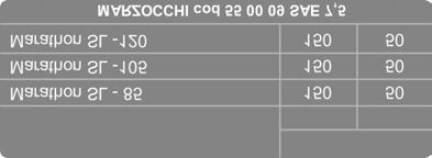
 Technical instructions Exploded view - Marathon SL Doppio Air Marathon SL Doppio Air - Oil levels Position Oil type Quantity (cc) Right fork leg SAE 7,5-550013 40 Rif. Code Quantity 1 818333/E 1 1 818333/R
Marzocchi Suspension MX Pro TAS MX Pro TAS. Technical instructions
 Technical instructions Exploded view - MX Pro TAS 100 > 120 Rif. Code Quantity 1 818340/A 1 1 818340/E 1 1 818340/R 1 3 522244AA 3 5 524127>A 1 7 549072KR 1 8 528226 2 11 701208/C 1 21 523011 1 22 520313
Marzocchi Suspension Z1 SL Doppio Air Z1 SL Doppio Air. Technical instructions
 Technical instructions Exploded view - Z1 SL Doppio Air Rif. Code Quantity 1 818268/E 1 1 818268/R 1 2 549073AD 1 3 701258/C 1 4 528226 2 5 528247 1 6 520313 1 7 549081LA 1 8 531076 1 9 525007 1 10 520220AA
Marzocchi Suspension Light ETA Light ETA. Technical instructions
 Technical instructions Exploded view - 66 Light ETA - 150 Rif. Code Quantity 66 Light ETA - 150 - Oil levels Position Oil type Quantity (cc) Left fork leg SAE 7,5-550013 205 Right fork leg SAE 7,5-550013
Marzocchi Suspension VF VF2. Technical instructions
 Technical instructions Exploded view - 66 VF2-170 Rif. Code Quantity 1 818370/E 1 1 818370/A 1 1 818370/R 1 2 549098LA 2 3 701296/C 2 4 528188 2 5 5081001/C 1 5 508996CD/C 1 6 518016 2 7 5141330/C 1 8
Marzocchi Suspension RC2X RC2X. Technical instructions
 Technical instructions Exploded view - 66 RC2X - 150 Rif. Code Quantity 1 818369/A 1 1 818369/E 1 1 818369/R 1 4 528188 2 6 5081001/C 1 6 508996CD/C 1 7 549097AC 2 8 549094LA 1 9 523294 2 10 528265 2 11
Jr. T GENERAL. BAM: Bomber Aerospace Material. Special alloy extracted from aerospace material. Ø TRAVEL ±
 175 15 GENERAL The double clamp fork is specifically designed for Downhill use. The fork is sprung by a mechanical spring and uses hydraulic rebound damping. Spring pre-load adjustment controlled via external
Z5 Coil (80) GENERAL. BAM: Bomber Aerospace Material. Special alloy developed from aerospace material. Ø TRAVEL 80 55
 GENERAL. BAM: Bomber Aerospace Material. Special alloy developed from aerospace material. Ø TRAVEL 80 55") (8) 175 8 Ø3 +.5 L.MAX=461 L.L.=451 L.MIN=371 ±2 396 ±2 TRAVEL 8 55 18 Ø3 15 2 -.1 +1 248.5 GENERAL The fork is sprung by a mechanical coil system and uses hydraulic rebound damping. Spring pre-load adjustment
(8) 175 8 Ø3 +.5 L.MAX=461 L.L.=451 L.MIN=371 ±2 396 ±2 TRAVEL 8 55 18 Ø3 15 2 -.1 +1 248.5 GENERAL The fork is sprung by a mechanical coil system and uses hydraulic rebound damping. Spring pre-load adjustment
Z3 Air (80) GENERAL. BAM: Bomber Aerospace Material. Special alloy developed from aerospace material. Ø TRAVEL 80 L.MAX=461 L.L.=451 L.
 GENERAL. BAM: Bomber Aerospace Material. Special alloy developed from aerospace material. Ø TRAVEL 80 L.MAX=461 L.L.=451 L.") (80) 175 18 80 Ø30 +0.05 0 55 L.MAX=461 L.L.=451 L.MIN=371 396 ±0,1 TRAVEL 80 ±2 Ø30 15 20 0-0.1 +1 0 248 GENERAL Special air/oil damped cross-country fork: each leg uses pressurized air blown through
(80) 175 18 80 Ø30 +0.05 0 55 L.MAX=461 L.L.=451 L.MIN=371 396 ±0,1 TRAVEL 80 ±2 Ø30 15 20 0-0.1 +1 0 248 GENERAL Special air/oil damped cross-country fork: each leg uses pressurized air blown through
Z1 Free Ride (110) GENERAL
 GENERAL") GENERAL (110) 175 80 Ø 30 +0.05 0 L.MAX=493 L.L.=483 ±2 L.MIN=373 426 ±2 57 CORSA 110 TRAVEL 110 18 Ø 30 15 20 0-0.1 +1 0 248.5 Special ride and Downhill fork whose legs are damped by a spiral springs
GENERAL (110) 175 80 Ø 30 +0.05 0 L.MAX=493 L.L.=483 ±2 L.MIN=373 426 ±2 57 CORSA 110 TRAVEL 110 18 Ø 30 15 20 0-0.1 +1 0 248.5 Special ride and Downhill fork whose legs are damped by a spiral springs
10A 10F 10B 10E 10A 10D 10B. Mr. T 10C Q R
 Q R 2 0 23 30 12 18 17 16 15 14 37 39 38 3 7 6 5 20 26 21 22 40 13 4 2 25 24 8 1 28 27 11 31 19 10A 10D 10B 10C 10 29 10A 10F 10B 10E 10 9 32 36 33 34 35 178 15 GENERAL 82 80 Ø28.6 ±0.1 Ø30 +0.05 0 348
X-FLY (80) GENERAL. BAM: Bomber Aerospace Material. Special alloy developed from aerospace material. Ø TRAVEL Ø30
 GENERAL. BAM: Bomber Aerospace Material. Special alloy developed from aerospace material. Ø TRAVEL Ø30") (8) 175 8 Ø3 +.5 L.MAX=461 L.L.=451 L.MIN=371 ±2 396 ±2 TRAVEL 8 55 18 Ø3 15 2 -.1 +1 248.5 GENERAL Special air/oil damped cross-country fork: each leg uses pressurized air blown through a special valve
(8) 175 8 Ø3 +.5 L.MAX=461 L.L.=451 L.MIN=371 ±2 396 ±2 TRAVEL 8 55 18 Ø3 15 2 -.1 +1 248.5 GENERAL Special air/oil damped cross-country fork: each leg uses pressurized air blown through a special valve
Z3 Coil (80) GENERAL. BAM: Bomber Aerospace Material. Special alloy developed from aerospace material. Ø TRAVEL 80 55
 GENERAL. BAM: Bomber Aerospace Material. Special alloy developed from aerospace material. Ø TRAVEL 80 55") (8) 175 8 Ø3 +.5 L.MAX=461 L.L.=451 L.MIN=371 ±2 396 TRAVEL 8 55 18 Ø3 15 2 -.1 +1 248.5 GENERAL The fork is sprung by a mechanical coil system and uses hydraulic rebound damping. Spring pre-load adjustment
(8) 175 8 Ø3 +.5 L.MAX=461 L.L.=451 L.MIN=371 ±2 396 TRAVEL 8 55 18 Ø3 15 2 -.1 +1 248.5 GENERAL The fork is sprung by a mechanical coil system and uses hydraulic rebound damping. Spring pre-load adjustment
Z3 QR20 (110) GENERAL
 GENERAL") (11) 175 18 8 Ø3 +.5 L.MAX=491 L.L.=481 ±2 L.MIN=371 426 55 ±2 TRAVEL 11 Ø3 15 2 -.1 +1 248.5 GENERAL The fork is sprung by a mechanical coil system and uses hydraulic rebound damping. Spring pre-load
(11) 175 18 8 Ø3 +.5 L.MAX=491 L.L.=481 ±2 L.MIN=371 426 55 ±2 TRAVEL 11 Ø3 15 2 -.1 +1 248.5 GENERAL The fork is sprung by a mechanical coil system and uses hydraulic rebound damping. Spring pre-load
Super T QR20 INSTRUCTIONS GENERAL RULES
 INSTRUCTIONS GENERAL RULES 1. Where specified, assemble and disassemble the shock absorption system using the MARZOCCHI special tools only. 2. On reassembling the suspension system, always use new seals.
Super T QR20 GENERAL. BAM: Bomber Aerospace Material. Special alloy extracted from aerospace material Ø30 +0.
 175 15 GENERAL 80 Ø30 +0.05 0 L.MAX=726.8 L.L.=716.8 L.MIN=566.8 ±2 273 ±2 523 193.8 RAVEL 150 49 35 15 20 0-0.1 +1 0 248.5 he double clamp fork is specifically designed for Downhill use. he fork is damped
KIT 8 9 9A Q R 15A 15B. yyy
 ,,,,, yy yyy 3 8 9 9A 6 7 6A 5 3 3 1 11 1 13 14 34 15A 15B 15 16 17 4 5 3 8 6 7 9 31 1 18 19 1 33 4 41 35 39 38 37 36 4 KIT 178 8 8 348 ± L.MAX=51.5 L.L.=5.5 L.MIN=37.5 ± 44 58.5 TAVEL 13 15 1 Ø3 43 48.5
KIT 10 10A 10D 10B 10C Z1 Q R 10A 10F 10B 10E
 11 9 1 13 3 17 18 16 9 3 3 4 5 6 7 8 8 1 14 15 7 19 6 5 4 3 33 31 1 37 13 1 1E 1B 1F 1A 1 9 36 34 35 1 1A 1D 1B 1C 38 KIT 178 15 GENEAL 8 8 348 L.MAX=51.6 L.L.=5.6 L.MIN=37.6 ± ± 44.1 TAVEL 13 58.5 1 Ø3
Z1 Free Ride INSTRUCTIONS GENERAL RULES
 INSTRUCTIONS GENERAL RULES 1. Where specified, assemble and disassemble the shock absorption system using the MARZOCCHI special tools only, as shown in the table below. 2. On reassembling the suspension
Monster T GENERAL. Travel 175
 Ø22 112.5 175 Ø20 358 L.MAX=728 L.L.=718 ±2 L.MIN=543 267 550.5 142.5 25 155.5 37 ±2 513.5 RAVEL 175 38 +0.5 0 27 ravel 175 17.4 192.5 GENERAL he double plate fork is specifically designed for Downhill
S USP E N S I O N I N N O VAT I O N F I F T Y Y E A RS O F CE 1949 SINCE 1949 SINCE 1949
 S USP E N S I O N I N N O VAT I O N F I F T Y Y E A RS O F CE 199 SINCE 199 SINCE 199 INDEX Page OWNER S INFORMATION... 2 GENERAL SPECIFICATIONS... 3 GENERAL RULES FOR A CORRECT OVERHAULING AND MAINTENANCE...
KIT 8 9 9A D R O P 15A 15B. yyy O F F
 ,,,,, yy yyy 30 8 9 9A 6 7 6A 5 3 2 1 10 11 12 13 14 35 15A 15B 15 16 17 24 25 23 28 26 27 29 31 36 37 32 18 19 20 21 22 33 34 38 KIT 178 15 GENEAL 82 80 4 348 ±2 L.MAX=510.5 L.L.=500.5 L.MIN=370.5 ±2
ISTRUZIONI PER L USO E LA MANUTENZIONE
 3 Deutsch Français Italiano MONSTER 2003 Español ISTRUZIONI PER L USO E LA MANUTENZIONE USE AND MAINTENANCE INSTRUCTION MANUAL MODE D EMPLOI ET ENTRETIEN BETRIEBS - UND WARTUNGSANLEITUNG INSTRUCCIONES
Marzocchi Suspension All Mountain II ETA All Mountain II ETA. Technical instructions
 Technical instructions Exploded view - All Mountain II ETA - 130 Rif. Code Quantity 1 818352/E 1 1 818352/A 1 1 818352/R 1 2 549072KR 1 3 701211/C 1 4 528226 2 8 703769LA/C 1 9 521142IW>A 1 10 5141420/C
2 3 Z2 4 5 X Q R F L Y
 3 Z 4 5 9 1 11 1 13 14 16 15 6 7 8 1 8 9 3 4 36 4 3 7 5 6 31 17 1 35 19 18 34 3 3 33 18 Z 178 8 8 348 ±.MA=46.5..=45.5.MIN=37.5 ± 395.5 TAVE 8 55 18 Ø3 43 48.5 GENEA Special air/oil damped cross-country
Öhlins Front Fork for. Motocross and Enduro. Owner s Manual
 Öhlins Front Fork for Motocross and Enduro Owner s Manual Safety Precautions The front fork is a very important part of the vehicle and will therefore affect the stability. Read and make sure that you
General warnings for owners manual
 General warnings for owners manual 8 WARNING Failure to follow these instructions could result in failure of the product, an accident, personal injury or death. 1. USE OF THE MANUAL Carefully read, follow
I. USE OF THE MANUAL. Never make any modifications whatsoever to any component of your forks.
 8 I. USE OF THE MANUAL Carefully read, understand and follow the instructions given in this manual. This manual is an essential part of the product, and you should keep it in a safe place for future reference.
Difficulty Grading expert Wrench Time 1 hour Tip, Strip or Tune Strip Spares Needed Oil Seals 4.99 (pr), Dust Seals 5.75 (pr)
, Dust Seals 5.75 (pr)") URFNVKR[VHUYLFH Difficulty Grading expert Wrench Time 1 hour Tip, Strip or Tune Strip Spares Needed Oil Seals 4.99 (pr), Dust Seals 5.75 (pr) 22mm socket Rubber mallet Allen keys Small Phillips screwdriver
URFNVKR[VHUYLFH Difficulty Grading expert Wrench Time 1 hour Tip, Strip or Tune Strip Spares Needed Oil Seals 4.99 (pr), Dust Seals 5.75 (pr) 22mm socket Rubber mallet Allen keys Small Phillips screwdriver
Maverick American 3085 Bluff Street Boulder, CO Tel: Fax: ML7.2 SHOCK SERVICE MANUAL
 Maverick American 3085 Bluff Street Boulder, CO 80301 Tel: 303-415-0370 Fax: 303-415-0676 www.maverickamerican.com ML7.2 SHOCK SERVICE MANUAL 1. OVERVIEW 1.1. The Maverick ML7.2 rear shock is an oil damped
X-Trainer 43mm fork service manual. Beta USA, Inc This work should be performed by a trained motorcycle technician.
 X-Trainer 43mm fork service manual Beta USA, Inc. 2016 This work should be performed by a trained motorcycle technician. Table of contents Page Introduction/special tools... 2 Fork exploded view... 3 Legend.
Maverick American 3085 Bluff Street Boulder, CO Tel: Fax: ML7.0 SHOCK SERVICE MANUAL
 Maverick American 3085 Bluff Street Boulder, CO 80301 Tel: 303-415-0370 Fax: 303-415-0676 www.maverickamerican.com ML7.0 SHOCK SERVICE MANUAL 1. OVERVIEW 1.1. The Maverick ML7.0 rear shock is an oil damped
Spring manual V3.1 ENGLISH
 Spring manual V3.1 ENGLISH HYPERPRO TOOLS, used in this manual: Tool Description Part no. A, B, C Cartridge fork spring removal tool kit HP-T01 D Big Piston Fork end cap socket 45mm HP-T102 E Big Piston
FRONT FORK 2.16 GENERAL REMOVAL HOME. 4. See Figure Loosen upper and lower fork clamp pinch fasteners (1, 4).
.") FRONT FORK.6 GENERAL The XRScg model utilizes a mm fork assembly while all other models have changed to the mm fork assembly. The front fork consists of two telescoping outer tube/inner slider assemblies.
FRONT FORK.6 GENERAL The XRScg model utilizes a mm fork assembly while all other models have changed to the mm fork assembly. The front fork consists of two telescoping outer tube/inner slider assemblies.
Sachs 48mm Closed Cartridge fork Service Manual
 Sachs 48mm Closed Cartridge fork Service Manual 1 Fork seal driver 2 Special soft jaws 3 Fork cap wrench 4 Rebound rod holding tool 5 Compression assembly holding tool 6 Retaining clip tool Special Tools
Owners Manual Öhlins road & track front fork FG 43 Including:
 Owners Manual Öhlins road & track front fork FG 43 Including: Safety Adjusters Setting up your fork Changing springs Oil level adjustment Technical information Inspection & maintenance Service Tools 1
PIKE DUAL AIR PICTORIAL INSTRUCTIONS. INSTRUCTIONS FOR INSTALLING ENDURO FORK SEALS AND CHANGING SEMI-BATH OIL in RockShox PIKE Dual Air Forks
 INSTRUCTIONS FOR INSTALLING ENDURO FORK SEALS AND CHANGING SEMI-BATH OIL in RockShox PIKE Dual Air Forks RECOMMENDED PARTS AND TOOLS -Bicycle work stand -Plastic bucket/drain pan -5mm Allen wrench -DH
Sachs shock manual. ( ) 2 & 4 Stroke RR Enduro. ( ) RS Dual Sport
 2 & 4 Stroke RR Enduro. ( ) RS Dual Sport") Sachs shock manual (2013 2015) 2 & 4 Stroke RR Enduro (2014-2015) RS Dual Sport 1 Introduction The procedures in this manual must take place in a clean environment using professional tools and some specific,
Sachs shock manual (2013 2015) 2 & 4 Stroke RR Enduro (2014-2015) RS Dual Sport 1 Introduction The procedures in this manual must take place in a clean environment using professional tools and some specific,
FGGG 992. Owner s Manual - Mounting Instructions. Öhlins Front Fork Kit for Gas Gas EC 300. Note! Warning!
 Before installing this product, check the contents of the kit. If anything is missing, please contact your Öhlins dealer. Kit Contents Part No Pcs Front Fork kit FGGG 992 1 O-ring 00338-10 2 O-ring 00438-97
Öhlins Front Fork Kit for. Motocross and Enduro. Owner s Manual - General Mounting Instructions
 Öhlins Front Fork Kit for Motocross and Enduro Owner s Manual - General Mounting Instructions Safety Precautions Safety Symbols The front fork is a very important part of the vehicle and will therefore
M O N S T E R 10 10A 10F 10B 10E 10 10A 10D 10B 10C
 M 12 18 17 16 39 14 3 7 15 32 33 32 13 2 8 1 9 8A 11 30 20 30 27 27 26 28 28 29 31 29 31 29 25 24 19 34 29 21 22 23 4 6 5 35 10 10A 10F 10B 10 37 38 36 40 41 10 10A 10D 10B 10C M Ø22 112.5 175 Ø20 358
Spare parts list. Hydraulic breakers RX Valid from serial number
 Hydraulic breakers Valid from serial number 50 www.cp.com Contents Contents General information............................................................... 5....................................................................
Öhlins Front Fork Road & Track FG 43. Owner s Manual
 Öhlins Front Fork Road & Track FG 43 Owner s Manual Öhlins Headquarters Upplands Väsby, Sweden Öhlins Racing AB - The Story It was the 1970 s, a young man named Kenth Öhlin spent most of his spare time
Spare parts list. Hydraulic breakers RX Valid from serial number
 Hydraulic breakers Valid from serial number 50 www.cp.com Contents Contents General information............................................................... 5....................................................................
CHASSIS CONTENTS EXTERIOR PARTS 7-1 FRONT WHEEL 7-2 FRONT BRAKE 7-6 HANDLEBARS 7-13 FRONT FORK 7-15 STEERING 7-23 REAR WHEEL 7-26 REAR BRAKE 7-30
 CHASSIS CONTENTS EXTERIOR PARTS 7- FRONT WHEEL 7-2 FRONT BRAKE 7-6 HANDLEBARS 7-3 FRONT FORK 7-5 STEERING 7-23 REAR WHEEL 7-26 REAR BRAKE 7-30 REAR SHOCK ABSORBER 7-32 SWING ARM 7-33 7 7- CHASSIS EXTERIOR
Owner s Manual Wren Inverted Suspension Forks
 Owner s Manual Wren Inverted Suspension Forks with Keyed Stanchions TwinAir System Carbon Bash Guards 2 - Travel/AC Clips 2 - Hose/Cable Guides 43mm Uppers 36mm Stanchions Check out our service videos
 .1..2..3..4..5..6..7..8..9..10. MANITOU SUSPENSION FORKS CONGRATULATIONS ON CHOOSING A 2003 MANITOU SIX FORK. This Manitou SIX fork is fully assembled and ready to be installed onto your bicycle. It comes
Level 1 and Level 2/3 Fork Upgrade Fitting Instructions
 Fitting Instructions for Honda CB500X/F Level 1 and Level 2/3 Fork Upgrade Fitting Instructions Ensure bike is securely mounted on suitable stand or scissor lift, if our Engine Guard RRP 437, is fitted.
MULTISTRADA 1200 S (ALL COUNTRY VERSIONS)
") Date: 13/09/2011 Subject: Models: FRONT END KNOCK ON OHLINS FORKS MULTISTRADA 1200 S (ALL COUNTRY VERSIONS) Dear Dealer, We hereby inform you about the technical solution to fix the above-mentioned fault;
Date: 13/09/2011 Subject: Models: FRONT END KNOCK ON OHLINS FORKS MULTISTRADA 1200 S (ALL COUNTRY VERSIONS) Dear Dealer, We hereby inform you about the technical solution to fix the above-mentioned fault;
Hayes Performance Systems 5800 W. Donges Bay Rd. Mequon, WI 53092
 01 Hayes Performance Systems 5800 W. Donges Bay Rd. Mequon, WI 5309 Tel: 888.686.347 Email: techsupport@hayesbicycle.com Web: www.hayescomponents.com Hayes Components Europe Dirnismaning 0 a 85748 Garching
4357 / 4860 MX Multi Adjuster
 12_234 Frontfork 4357 / 4860 MX Multi Adjuster Introduction 2 Exploded view 3 Disassembly forkleg 4 Disassembly screw-cap 15 Assembling screw-cap 17 Disassembly cartridge 18 Disassembly compression holder
Owners manual Competition Shock absorber. WP Suspension Netherlands
 Owners manual 4618 Competition Shock absorber WP Suspension Netherlands 1 INTRODUCTION: Congratulations on your purchase of this WP Suspension shock absorber, The shock absorber that won the 2001/2002/2003/2004/2005/2006
SERVICE MANUAL. Hydraulic Motors type MTM
 SERVICE MANUAL Hydraulic Motors type MTM and Сервизно ръководство Демонтаж Хидравлични мотори Тип GW Dust Front Cap 2008 and Bearing Kit Dust Front Cap Ring 90x1,5 "C" and Bearing Kit Ring 90x1,5 "W" Dust
1. Get fork mounted in stand. You can leave it in the bike, but you must remove the wheel and front brake.
 Tools Needed: Bike stand Lint free shop Towels 1.5mm Allen Key Pick Set Grease (We recommend Slick Honey) Oil Measuring Cup (with cc Scale) Small Metal Drift Shop Vise Oil Bucket 13mm Deep Socket (6 point)
Owners manual. Öhlins Superbike front fork FG 170
 Owners manual Öhlins Superbike front fork FG 0 Including: Setting up your fork Changing springs and seals Service the fork Trouble shooting Technical info Spare parts & tools Öhlins super bike front fork
OWNERS MANUAL HEADSHOK FORKS
 OWNERS MANUAL HEADSHOK FORKS 1998 HEADSHOK MOTO FR INSTRUCTIONS The HeadShok Moto FR combines the versatility of a triple-clamp fork with the superior stiction-free performance of all the HeadShok forks.
2004 SERVICE MANUAL Six Six Sport Avenue Stanford, Valencia, California fax
 2004 SERVICE MANUAL Six Six Sport 28209 Avenue Stanford, Valencia, California 91355 661 257-4411 fax 661 294-4179 www.answerproducts.com Table of Contents Description Page Introduction 3 Front Suspension
Sub Section Title Page No.
 Sub Section Title Page No. 1 Introduction 3 2 Routine Maintenance 3 3 Disassembly 4 3.1 Disassembly of Double Crank Design 4 3.2 Disassembly of Scotch Yoke Design 5 3.3 Disassembly of Actuator Cylinder
Wren Inverted Suspension Forks with Keyed Stanchions and TwinAir System
 Owner s Manual Wren Inverted Suspension Forks with Keyed Stanchions and TwinAir System Congratulations You have just purchased a Wren Inverted Suspension Fork. The culmination of years of design, testing
FITTING INSTRUCTIONS YAMAHA YZF-R3
 FITTING INSTRUCTIONS YAMAHA YZF-R3 120-015-270-005 20/07/2017 ISSUE 1 2 IMPORTANT NOTES KEY NB NOTE! CAUTION! WARNING! NB NB NB The front forks are a very important part of the motorcycle and will affect
Öhlins Front Fork Superbike FGR 900. Owner s Manual
 Öhlins Front Fork Superbike FGR 900 Owner s Manual Introduction Öhlins Racing AB - The Story It was the 1970 s, a young man named Kenth Öhlin spent most of his spare time pursuing his favourite sport:
K2 Smart Fork Owner s Manual Addendum
 K2 Smart Fork Owner s Manual Addendum K2 Bike 19215 Vashon Hwy SW Vashon, WA 98070 INTRODUCTION Congratulations and thank you for purchasing the best performing, most technologically advanced suspension
For exploded diagram and part number information, refer to the Spare Parts Catalog available on our website at
 For exploded diagram and part number information, refer to the Spare Parts Catalog available on our website at www.rockshox.com. Contact your local distributor or visit the RockShox website at www.rockshox.com
Front mechanical suspensions
 FRONT MECHANICAL SUSPENSIONS 9 PRINT 603.43.351/D Front mechanical suspensions Page DESCRIPTION... 11 ARTICULATED QUADRILATERAL SUSPENSION WITH TRANSVERSE LEAF SPRING... 11 SPECIFICATIONS AND DATA... 12
Shock Absorber Rebuild Manual
 Shock Absorber Rebuild Manual Model PODIUM RC3 FOX RACING SHOX 130 Hangar Way, Watsonville, CA 95076 PHONE 800.369.7469 FAX 831.768.7026 Email: psservicemw@ridefox.com Website: www.ridefox.com Disclaimer
Hayes Performance Systems 5800 W. Donges Bay Rd. Mequon, WI Tel: Web:
 Hayes Performance Systems 5800 W. Donges Bay Rd. Mequon, WI 53092 Tel: 888.686.3472 Email: techsupport@hayesbicycle.com Web: www.hayescomponents.com Hayes Components Europe Dirnismaning 20 a 85748 Garching
TOPAZ Service Guide. Full Service
 TOPAZ Service Guide Full Service SERVICE OVERVIEW This manual will guide you step by step performing an air service to your Topaz. Please follow each instruction carefully to achieve the best and safest
H15P. Toyota Hilux A-DECK Dual Cab
 Toyota Hilux A-DECK Dual Cab Page 1 of 14 Fitting Instructions Part Number H15 Toyota Hilux A-DECK Dual Cab 2015+ To suit Sports Bars Check contents of kit before commencing fitment and report any discrepancies
Model year 2014 USER MANUAL
 Model year 2014 USER MANUAL WARRANTY Terms and conditions BOS MTB offers warranty on its products on the following terms: BOS MTB guarantees to the original purchaser that the BOS product for which they
OWNERS MANUAL. LINK & PDS Trax shock absorber.
 OWNERS MANUAL LINK & PDS Trax shock absorber Introduction: Congratulations on your purchase of the WP Trax Off-road shock absorber. The WP Trax shock absorber has a unique system, which provides better
4ZA OWNERS MANUAL 4ZA OWNERS MANUAL FOR FAST FORK RACE
 4ZA OWNERS MANUAL 4ZA OWNERS MANUAL FOR FAST FORK RACE GENERAL Read this manual carefully before using your 4ZA FAST fork and setting up the integrated brakes. This complex and technically advanced product
Suzuki GS1000G fork seal replacement
 Suzuki GS1000G fork seal replacement Before you start you require: 1) To read workshop service manual for your model 2) Socket allen key M8 3) Torque wrench 4) Special tool to hold inner, make your own,
MAINTENANCE PROCEDURE FOR MK21
 MAINTENANCE PROCEDURE FOR MK21-1 - MAINTENANCE PROCEDURE FOR MK 21 1 ST STAGE WARNING: this maintenance procedure is only for appointed Scubapro technicians that followed a complete course on equipment
w w w. h d o n l i n e s h o p. d e FLHT FRONT END LOWERING KIT GENERAL -J02546 REV Kit Number Models Additional Parts Required
 -J0546 REV. 007--0 GENERAL Kit Number 5468-06 Models For model fitment information, please see the P&A Retail Catalog or the Parts and Accessories section of www.harleydavidson.com (English only). Additional
DM-ST (English) Dealer's Manual. Dual control lever ST-9001 ST-9000 ST-6800 ST-5800 ST-4700 ST-4703
 Dealer's Manual. Dual control lever ST-9001 ST-9000 ST-6800 ST-5800 ST-4700 ST-4703") (English) DM-ST0002-05 Dealer's Manual Dual control lever ST-9001 ST-9000 ST-6800 ST-5800 ST-4700 ST-4703 CONTENTS IMPORTANT NOTICE... 3 TO ENSURE SAFETY... 4 INSTALLATION... 6 List of tools to be used...6
(English) DM-ST0002-05 Dealer's Manual Dual control lever ST-9001 ST-9000 ST-6800 ST-5800 ST-4700 ST-4703 CONTENTS IMPORTANT NOTICE... 3 TO ENSURE SAFETY... 4 INSTALLATION... 6 List of tools to be used...6
INSTRUCTION MANUAL INTERNAL GEAR PUMP TITAN G-4124A SERIES=> FLANGED TITAN G-124A SERIES => FLANGED MODELS:
 INSTRUCTION MANUAL INTERNAL GEAR PUMP TITAN G-4124A SERIES=> FLANGED TITAN G-124A SERIES => FLANGED MODELS: G-H, G-HL, G-K, G-KK, G-L, G-LQ, G-LL, GLS, G-Q, G-QS 1 Contents Maintenance Thrust bearing adjustment
Service Instruction Front Suspension PASHLEY-MOULTON. 1.0 General Description. 2.0 Adjustment
 Service Instruction Front Suspension PASHLEY-MOULTON 1 General Description 2 Adjustment 3 Problems and their Remedies 3.1 Clunking or Banging Noises 3.2 Suspension Squeaking 3.3 Seized Suspension 4 Disassembly
2006 SID SERVICE GUIDE
 2006 SID SERVICE GUIDE For exploded diagram and part number information, refer to the Spare Parts Catalog available on our website at www.rockshox.com. Information contained in this publication is subject
Installation and Maintenance Manual MRW-01. Radial Winch 20 ST
 MRW-01 Index Introduction Technical characteristics Weight Maximum working load Outline Installation Procedure 1 Procedure 2 Installation procedure Positioning the self-tailing arm Maintenance Washing
WARRANTY INFORMATION AMERICAN MADE MANITOU SUSPENSION
 AMERICAN MADE MANITOU SUSPENSION CONGRATULATIONS ON CHOOSING THE LATEST IN SUSPENSION TECHNOLOGY AVAILABLE, A 2003 MANITOU DORADO FORK BUILT IN THE USA. This DORADO fork is fully assembled and is ready
DUAL AIR SERVICE GUIDE
 1999-2004 DUAL AIR SERVICE GUIDE For exploded diagram and part number information, refer to the Spare Parts Catalog available on our website at www.rockshox.com. Contact your local distributor or visit
Operating and Installation Instructions Diaphragm Vacuum Pumps and Compressors
 Operating and Installation Instructions Diaphragm Vacuum Pumps and Compressors Type range: UN813.3ANI UN813.4ANI UN813.3ANDCB UN813.4ANDCB UN813.5ANI Fig. 1: UN813.3ANI Fig. 2: UN813.4ANI You have selected
ORDER ON-LINE /
 NM249 NM248 INTERNAL SYSTEMS FOR TRAILERS INSTALLATION MANUAL VERSION 1-2013 ORDER ON-LINE www.vigia.ca / 1-888 438-8444 IMPORTANT Installation requires an experienced mechanic with knowledge of tools
INSTRUCTION MANUAL FOR ASSEMBLING/DISASSEMBLING
 INSTRUCTION MANUAL FOR ASSEMBLING/DISASSEMBLING BLUE SERIES PUMPS INDEX Disassembling Blue90 pump Hydraulic section... 3 Opening the oil sump... 6 Removing the mechanical seals... 8 Removing ball bearings...
fkc 102 Mounting Instructions Cartridge kit for Harley-Davidson Touring FLHx/ FLTx 2014-
 Kit Contents Description Part No Pcs Cartridge kit FKC102 1 Sticker 01185-04 2 Owner s manual 07288-01 1 Guide ring 21808-01 2 Please note that there can be small differences between your product and the
Winwood DeeDee 29" Carbon Suspension Fork. Owner s Manual
 Winwood DeeDee 29" Carbon Suspension Fork Owner s Manual Congratulations! You have just purchased one of the most advanced forks available on the market. This Winwood fork features a unique and consumer-friendly
Installation and Maintenance Manual MRW-02. Radial Winch 20 ST
 MRW-02 Index Introduction 3 Technical characteristics 3 Weights 3 Maximum working load 3 Outline 3 Installation 4 Procedure 1 5 Procedure 2 6 Installation procedure 8 Positioning the self-tailing arm 9
Heavy duty slurry pumps
 USERS MANUAL Heavy duty slurry pumps TOYO PUMPS EUROPE Edition 27.07.2007 SAFETY INSTRUCTIONS TOYO PUMPS EUROPE Users manual for Toyo pumps type «DP..-6 30~40HP» This users manual will help you to maintain
CHASSIS CONTENTS EXTERIOR PARTS 6-1 FRONT WHEEL 6-2 FRONT BRAKE 6-6 HANDLEBARS 6-12 REAR WHEEL 6-30 REAR BRAKE 6-34 REAR SHOCK ABSORBER 6-36
 CHASSIS CONTENTS EXTERIOR PARTS 6-1 FRONT WHEEL 6-2 FRONT BRAKE 6-6 HANDLEBARS 6-12 FRONT FORK ( ) 6-14 FRONT FORK ( ) 6-20 STEERING 6-27 REAR WHEEL 6-30 REAR BRAKE 6-34 REAR SHOCK ABSORBER 6-36 6 SWING
Brake Upgrade Kit Fitting Instructions Bonneville America
 WARNING: Always have Triumph approved parts, accessories and conversions fitted by a trained technician of an authorised Triumph Dealer. The fitment of parts, accessories and conversions by a technician