Workshop manual 3612 / 4681 BAVP. Product Exploded View Disassembly & Assembling. Shock absorber
|
|
|
- Edward Barker
- 5 years ago
- Views:
Transcription

1 455 Shock absorber 3612/4681 BAVP 02/2002 Shock absorber Introduction 2 Exploded view 3 Adjustment 4 Disassembly shock absorber 5 Disassembly piston-rod 7 Disassembly adaptor DU-bush 15 Disassembly tube side 18 Disassembly heim-joint KGW 24 Assembling heim-joint KGW 26 Assembling piston-rod 28 Assembling adaptor DU-bush 35 Assembling tube side 40 Bleeding 53 Under pressure with nitrogen 58 Assembling the spring 59 Adjusting 61 1
2 Introduction General notice Pay attention to the following notes, when you are working with WP Suspension products as described in this workshop manual. Always use clean and professional tools. Regular you need next to the general equipment, the special tools of WP Suspension. These tools with an unique T number (available by WP Suspension) protect you from damaging the parts. Always use aluminium protector-plates, when clamping our products or parts in the vice. Replace always damaged or worn parts. Clean all parts before assembling. Caution: Many times it is necesarry to assemble parts with T131, T132 and T163. These parts must to dry for at least four hours!! 2
3 Disassembly & assembling Exploded view 3
 of")


4 Adjustment Measure the length (preload) of the spring. 458 Take note of position compression Take note of position rebound. 4


5 Disassembly shock absorber Disassemble the spring with T101S and remove the open spring retainer. 459 Remove the spring Adjust the rebound to position 1. 5


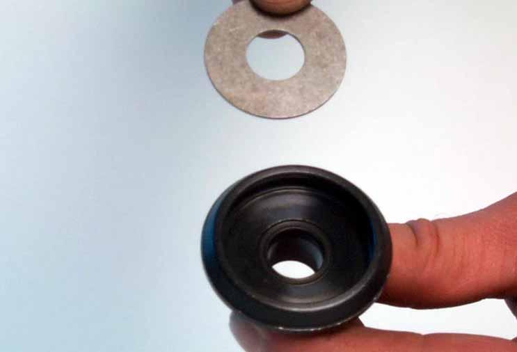
6 Remove the rubber cap. 464 Unscrew slowly the nitrogen plug and release the pressure Unscrew the screw-cap with T125S. 6


7 Lift the O-ring out of the tube. 469 Pull piston-rod complete out of the tube Disassembly piston-rod Unscrew piston-rod nut. (size 22) 7


8 Place a screwdriver on top of the pistonrod and remove the entire assembly. 568 The piston-rod nut BA. (Bleed Adjuster) Disassemble the piston-rod nut. 8
 476 - rebound bush")


9 - piston-rod nut - shims - bush - bleed bolt (Allen screw) rebound bush plane - compression shims - piston - rebound shims - washer Remove (should this be the case) the spacers. Pay attention to the assembling direction!!! 9


10 Remove adaptor DU-bush. 479 Remove the circlip and O-ring Remove the dirt scraper and screw-cap. 10


11 Remove the bump rubber. 482 Remove the steel washer and springring. 11

 486")

12 Take off the adjusting knob. 485 Remove the pin. (D4) Remove the position ring. 12


13 Remove the seal. 488 Clamp the piston-rod in the vice with T104S Heat the mounting fork / eye. 13


14 Unscrew the mounting fork / eye. 491 Remove mounting fork / eye Unscrew the seat with an Allenkey. (size 3) 14


15 Remove the seat. 494 Remove the adjusting needle BA Disassembly adaptor DU-bush Prise the rebound rubber out the adaptor DU-bush. 15


16 Remove the washer. 497 Remove the quad ring and back-up ring Disassemble with T105S the DU-bush. 16


17 Press the DU-bush out of ithe adaptor rebound rubber - washer - quad ring - back-up ring - DU-bush - adaptor 17


18 Disassembly tube side Unscrew the compression adjusting knob with Allenkey Remove the adjusting knob Remove the ball-steel. 18


19 Remove the lock washer. 507 Lift out the compression control mechanism Screw the screw-cap hand tight into the tube. 19


20 Heat the bottom. 510 Unscrew the tube with T146 and T BAVP with T146 and T Clamp the tube with T146 and T148 and heat the threaded bush BAVP with T146 and T


21 Unscrew the threaded bush with T BAVP with T Threaded bush with the spring retainers Disassemble the spring retainers with T BAVP with T


22 Heat reservoir near bottom. 517 Unscrew reservoir with T146 and T BAVP with T146 and T Push the separation piston out of the reservoir with T107S. 22


23 The separation piston. 520 Clamp reservoir into T146 and T BAVP with T146 and T Unscrew the screw-cap with T125S and T145S. 23


24 Disassembly heimjoint KGW Remove the seals on both sides. 429 Tap the adaptor bushes out of the heimjoint with T / 433 Tapping the adaptor bushes out. 24


25 Disassemble the heim-joint KGW with T130S with support of the vice seal - adaptorbush - heim-joint KGW - bottom - adaptor bush - seal 25


26 Assembling heim-joint KGW Drip on the innerside of bottom-eye T163 and mount heim-joint KGW with T129. (With the bevelled edge direction bottomeye) 311 Press the heim-joint into the bottom with the vice Assemble with T129 adaptor bush on one side... 26


27 ...and without tool the other side. 436 Assemble the seals in the groove of the bottom- eye


28 Assembling piston-rod Grease O-ring adjusting needle rebound with T Assemble the adjusting needle in piston-rod Drip T132 on thread of the mounting fork / eye. 28


29 Drip on thread piston-rod T Screw mounting fork / eye on the piston-rod Tighten the mounting fork / eye. 29

30 Replace the seal and the position ring


31 Place T107S through mounting fork / eye under the needle and adjust position ring in the highest position. 529 / 531 Assemble a new seat greased with T152 on the thread Tight seat light till T107S and turn two rotations backwards. 31


32 Grease the ring and pin with T159 and assemble the pin. 536 Grease innerside adjusting knob with T159 and replace the seal Assemble the adjusting knob and turn the knob to position 1. 32


33 Assemble the steel washer and springring. 541 Push needle downwards on pin with Allenkey size


34 Place T108 on top of the piston-rod BAVP with T Assemble the bump rubber Assemble the screw-cap. 34


35 Grease the innerside dirt scraper with T625 and assemble. 547 Replace the O-ring Assembling adaptor DU-bush Press DU-bush in adaptor with T150S. 35


36 Pressing DU-bush into adaptor with support of the vice. 550 Calibrate DU-bush with T149 and part of T150S Wet the mandrel with oil. Drive the calibration mandrel through the DU-bush. 36


37 Assemble the back-up ring. 558 Assemble the quad ring Assemble the washer. 37


38 After assembly the rebound rubber, check if the rubber can be rotate in the holder. 562 Assemble the DU-bush adaptor Should it be the case to assemble spacers, then place them with the flat side direction rebound rubber. 38


39 Replace the entire damping packet. 565 Screw the piston-rod nut on pistonrod and tighten the nut to a torque of 40Nm BAVP with 30Nm. 39


40 Assembling tube side Grease the O-ring of the separation piston with T BAVP: Assembly direction separation piston: With the flat side of the piston into direction flat side bottom BAVP: Assembly direction separation piston: With the hollow side of the piston into direction spherical surface bottom. 40
 always")


41 Assemble separation piston (with piston-ring) always into direction of the screw-cap. 573 Drip T132 on thread reservoir Drip T132 on the thread of the screw-cap. 41


42 Drip T132 on thread of the bottom. 577 Tighten the screw-cap and reservoir with T125S and T145S Assemble both spring retainers on threaded bush. 42


43 Drip T132 on thread of the tube and on the thread of the bottom Assemble the threaded bush until the end of thread of the tube. 43


44 Assemble the tube in the bottom. 583 Screw down with T146 and T BAVP with T146 and T Screw threaded bush against the bottom. 44


45 Tighten threaded bush with T BAVP with T Grease the O-rings with T158. Assembly compression control mechanism Assemble mechanism, so that the hole of this is facing the hole in the direction of the tube. 45


46 Push the mechanism with T160 past the lock washer groove. 590 Assemble the lock washer with flat side above Grease the upper side compression mechanism with T159 and place ball-steel next to the pin. 46


47 593 Push adjusting knob with the spring directly on the steel ball and tighten Allen screw. Adjust compression control mechanism to position 1. Push the separation piston with T107S to the bottom and slide O-ring as far as the screw-cap Fill the tube with oil about 15mm under the springring groove. 47


48 Place T110S in the tube and push the plunger downwards BAVP with T306S. 598 Push the separation piston downwards, and hold the tube side in a angle. (about 45 degrees) Repeat those procedures several times Adjust separation piston about 10mm from the bottom, O-ring on the shaft will be 10mm above the screw-cap. 48


49 Adjust oil level about 45mm under the edge of the tube and set compression adjusting knob on position Slide piston-rod complete into the tube and assemble the springring above the piston in the groove with support of /607...T155. Pull light the piston against the springring and hold this till assembly screw-cap BAVP with T
 609")

 the oil")
50 (Assemble the spacers) 609 Assemble adaptor DU-bush Remove (if necesarry) the oil above the adaptor with T137S. 50


51 Slide O-ring against the adaptor. 614 Slide dirts craper against the adaptor Screw the screw-cap into the tube. 51

52 Tighten the screw-cap with T125S


53 Bleeding Disassemble compression control mechanism. 508 Connect the adaptor ot T144S into the housing / 620 Ensure that there is sufficient oil in the bottle and that the hose is also full with oil. You will see air bubbles rising up through the hose. 53


54 Push the piston-rod slowly in and out. 621 Cant to a view times the shock absorber and repeat the procedures several times until all air is bled out Check the position of the separation piston with T107S. 54

")

55 Assemble mechanism without adjusting needle. (left handed thread) 370 Note: hole of mechanism facing hole direction tube


56 Screw the adjusting needle hand tight into mechanism. 373 Push compression control mechanism past lock washer groove Assemble lock washer with flat side above. 56


57 Replace the steel ball on the left position next to the pin. 331 Place the steel ball: By CC no. 11: the third position on the right side of the pin. By CC no. 16: next on the right side of the pin. 1. Assemble adjusting knob with spring on the steel ball

 in")
 and tighten the plug under pressure.")
58 On pressure with nitrogen Replace the nitrogen plug with O-ring several turns into the screw-cap. 625 Place the shock absorber (reservoir) in T170S and fill it with nitrogen (±20 sec.) and tighten the plug under pressure Assemble the rubber cap do not open 58


59 Assembling spring Turn mounting fork / eye parallel with bottom-eye. 629 Assemble the spring Assemble the open spring retainer with T101S. Closed side of the retainer on the end of the coil. 59


60 Adjust the spring preload. 632 Tighten the spring retainers with T BAVP with T


61 Adjusting Position rebound! 633 Position compression!
Workshop manual 5018 PDS Product Exploded View Disassembly & Assembling. Shock absorber 5018 PDS OEM Shock absorber 5018 PDS /2002
 Shock absorber 5018 PDS OEM 2000 Introduction 2 Exploded view 3 Disassembly shock absorber 4 Disassembly piston-rod 11 Disassembly adaptor DU-bush 15 Assembling adaptor DU-bush 17 Assembling piston-rod
Workshop manual 4618 BAVP 85 SX. Product Exploded View Disassembly & Assembling. Schok absorber 4618 BAVP 85 SX
 Schok absorber Introduction 2 Exploded view 3 Disassembly shock absorber 4 Disassembly piston rod 12 Assembling piston rod 23 Disassembly adaptor DU-bush 33 Assembling adaptor DU-bush 36 Disassembly tube
4357 / 4860 MX Multi Adjuster
 12_234 Frontfork 4357 / 4860 MX Multi Adjuster Introduction 2 Exploded view 3 Disassembly forkleg 4 Disassembly screw-cap 15 Assembling screw-cap 17 Disassembly cartridge 18 Disassembly compression holder
Sachs shock manual. ( ) 2 & 4 Stroke RR Enduro. ( ) RS Dual Sport
 2 & 4 Stroke RR Enduro. ( ) RS Dual Sport") Sachs shock manual (2013 2015) 2 & 4 Stroke RR Enduro (2014-2015) RS Dual Sport 1 Introduction The procedures in this manual must take place in a clean environment using professional tools and some specific,
Sachs shock manual (2013 2015) 2 & 4 Stroke RR Enduro (2014-2015) RS Dual Sport 1 Introduction The procedures in this manual must take place in a clean environment using professional tools and some specific,
Shock absorber for Automotive TTX36 P/ IL. Workshop Manual
 TTX6P TTX6IL Shock absorber for Automotive TTX6 P/ IL Workshop Manual Safety precautions General Warnings Note! The shock absorber/front fork/steering damper is an important part of the vehicle and will
REPAIRMANUAL
 REPAIRMANUAL2005-2007 WP SHOCK ABSORBER 5018 DCC 5018 SXS 5018 SMR REPARATURANLEITUNG MANUALE DI RIPARAZIONE MANUEL DE RÉPARATION MANUAL DE REPARACIÓN ART.NO.: 3.211.208-E 1 SPECIAL TOOLS 2 GENERAL INFORMATION
Sachs 48mm Closed Cartridge fork Service Manual
 Sachs 48mm Closed Cartridge fork Service Manual 1 Fork seal driver 2 Special soft jaws 3 Fork cap wrench 4 Rebound rod holding tool 5 Compression assembly holding tool 6 Retaining clip tool Special Tools
Owners manual Competition Shock absorber. WP Suspension Netherlands
 Owners manual 4618 Competition Shock absorber WP Suspension Netherlands 1 INTRODUCTION: Congratulations on your purchase of this WP Suspension shock absorber, The shock absorber that won the 2001/2002/2003/2004/2005/2006
Super T QR20 INSTRUCTIONS GENERAL RULES
 INSTRUCTIONS GENERAL RULES 1. Where specified, assemble and disassemble the shock absorption system using the MARZOCCHI special tools only. 2. On reassembling the suspension system, always use new seals.
X-Trainer 43mm fork service manual. Beta USA, Inc This work should be performed by a trained motorcycle technician.
 X-Trainer 43mm fork service manual Beta USA, Inc. 2016 This work should be performed by a trained motorcycle technician. Table of contents Page Introduction/special tools... 2 Fork exploded view... 3 Legend.
FITTING INSTRUCTIONS YAMAHA YZF-R3
 FITTING INSTRUCTIONS YAMAHA YZF-R3 120-015-270-005 20/07/2017 ISSUE 1 2 IMPORTANT NOTES KEY NB NOTE! CAUTION! WARNING! NB NB NB The front forks are a very important part of the motorcycle and will affect
Shock Absorber TTX44 for Honda CRF 150R HO Spare Parts List
 Shock Absorber TTX for Honda CRF 0R HO 990 Spare Parts List Safety Precautions Note! The shock absorber is a very important part of the vehicle and will therefore affect the stability of the vehicle. Read
BM 048 BMW F 650 GS Dakar
 Öhlins shock absorber 46 HRCS Your Öhlins shock absorber type 46 HRCS features the following adjusters: Compression damping adjuster Adjustments are made on top of the reservoir. Rebound damping adjuster
SU 201 Suzuki V-storm 1000
 Öhlins shock absorber 46 PRCS Your Öhlins shock absorber type 46 PRCS features the following adjusters: Compression damping adjuster (C) Adjustments are made on top of the reservoir. Rebound damping adjuster
Shock Absorber TTX39 for BMW R1200GS Rear BM Spare Parts List
 Shock Absorber TTX39 for BMW R1200GS Rear BM 6760 Spare Parts List Safety Precautions Note! The shock absorber is a very important part of the vehicle and will therefore affect the stability of the vehicle.
Maverick American 3085 Bluff Street Boulder, CO Tel: Fax: ML7.0 SHOCK SERVICE MANUAL
 Maverick American 3085 Bluff Street Boulder, CO 80301 Tel: 303-415-0370 Fax: 303-415-0676 www.maverickamerican.com ML7.0 SHOCK SERVICE MANUAL 1. OVERVIEW 1.1. The Maverick ML7.0 rear shock is an oil damped
Shock Absorber for Formula Student and Formula SAE TTX 25. Workshop Manual
 Shock Absorber for Formula Student and Formula SAE TTX 5 Workshop Manual SAFETY PRECAUTIONS General Warnings Note! The shock absorber is an important part of the vehicle and will affect the stability.
Ducati 899/959 Panigale (Showa) FKR Spare Parts List Workshop Manual
 FKR Spare Parts List Workshop Manual") Ducati 899/99 Panigale (Showa) FKR 11 0 Spare Parts List Workshop Manual SAFETY PRECAUTIONS The shock absorber/front fork/steering damper is an important part of the vehicle and will affect the stability.
Ducati 899/99 Panigale (Showa) FKR 11 0 Spare Parts List Workshop Manual SAFETY PRECAUTIONS The shock absorber/front fork/steering damper is an important part of the vehicle and will affect the stability.
Front Fork Disassembling and Assembling RM-Z250L6. KAYABA Pneumatic Spring Front Fork PSF2
 Front Fork Disassembling and Assembling RM-Z250L6 KAYABA Pneumatic Spring Front Fork PSF2 RM-Z250L6 Front Fork Disassembling 1. Release air Release the air pressure by pressing the air valve with a screwdriver.
Shock Absorber Rebuild Manual
 Shock Absorber Rebuild Manual Model PODIUM RC3 FOX RACING SHOX 130 Hangar Way, Watsonville, CA 95076 PHONE 800.369.7469 FAX 831.768.7026 Email: psservicemw@ridefox.com Website: www.ridefox.com Disclaimer
Shock Absorber DUCATI MONSTER 821 DU Spare Parts List
 Shock Absorber DUCATI MONSTER 1 DU 0 Spare Parts List SAFETY PRECAUTIONS The shock absorber/front fork/steering damper is an important part of the vehicle and will affect the stability. After installing
BM 318. BMW K1200, rear. Öhlins shock adsorber 46 HRCLS CAUTION! Your Öhlins shock absorber type 46 HRCLS features the following adjusters:
 Öhlins shock adsorber 46 HRCLS Your Öhlins shock absorber type 46 HRCLS features the following adjusters: Rebound damping adjuster (R) Adjuster wheel on the piston shaft above the end bracket. Compression
Öhlins Front Fork for. Motocross and Enduro. Owner s Manual
 Öhlins Front Fork for Motocross and Enduro Owner s Manual Safety Precautions The front fork is a very important part of the vehicle and will therefore affect the stability. Read and make sure that you
TTX30 KTM 50SX KT Spare Parts List
 TTX30 KTM 50SX KT 397 Spare Parts List Safety Precautions General Warnings The shock absorber/front fork/steering damper is an important part of the vehicle and will affect the stability. Safety Symbols
Shock Absorber Triumph Speed Triple 1050 TR Spare Parts List
 Shock Absorber Triumph Speed Triple 00 TR 00 Spare Parts List Safety Precautions Note! The shock absorber is a very important part of the vehicle and will therefore affect the stability of the vehicle.
10A 10F 10B 10E 10A 10D 10B. Mr. T 10C Q R
 Q R 2 0 23 30 12 18 17 16 15 14 37 39 38 3 7 6 5 20 26 21 22 40 13 4 2 25 24 8 1 28 27 11 31 19 10A 10D 10B 10C 10 29 10A 10F 10B 10E 10 9 32 36 33 34 35 178 15 GENERAL 82 80 Ø28.6 ±0.1 Ø30 +0.05 0 348
Spare Parts List. BU TTX 36 Buell 1125 CR
 Spare Parts List BU 888 - TTX 36 Buell 1125 CR SPARE PARTS LIST BU 888 - TTX 36 Safety Precautions Note! The shock absorber is a very important part of the vehicle and will therefore affect the stability
TOPAZ Service Guide. Full Service
 TOPAZ Service Guide Full Service SERVICE OVERVIEW This manual will guide you step by step performing an air service to your Topaz. Please follow each instruction carefully to achieve the best and safest
INSTRUCTIONS Servicing PAH
 INSTRUCTIONS Servicing PAH 10-12.5 180R9095 Note: Dismantling: If the pump is dismantled during the warranty period, the pump is no longer under warranty. 180R9095 1. Tools required for dismantling the
Z1 Free Ride INSTRUCTIONS GENERAL RULES
 INSTRUCTIONS GENERAL RULES 1. Where specified, assemble and disassemble the shock absorption system using the MARZOCCHI special tools only, as shown in the table below. 2. On reassembling the suspension
Level 1 and Level 2/3 Fork Upgrade Fitting Instructions
 Fitting Instructions for Honda CB500X/F Level 1 and Level 2/3 Fork Upgrade Fitting Instructions Ensure bike is securely mounted on suitable stand or scissor lift, if our Engine Guard RRP 437, is fitted.
Maverick American 3085 Bluff Street Boulder, CO Tel: Fax: ML7.2 SHOCK SERVICE MANUAL
 Maverick American 3085 Bluff Street Boulder, CO 80301 Tel: 303-415-0370 Fax: 303-415-0676 www.maverickamerican.com ML7.2 SHOCK SERVICE MANUAL 1. OVERVIEW 1.1. The Maverick ML7.2 rear shock is an oil damped
Owners manual. Öhlins Superbike front fork FG 170
 Owners manual Öhlins Superbike front fork FG 0 Including: Setting up your fork Changing springs and seals Service the fork Trouble shooting Technical info Spare parts & tools Öhlins super bike front fork
FOX Racing Shox Bypass Technical Manual.
 FOX Racing Shox Bypass Technical Manual. The following technical manual will be using a 2.5 dia. shock with three tubes for descriptions and illustrations. Your shock may differ in the number of tubes,
Shock Absorber Rebuild Manual
 Shock Absorber Rebuild Manual Model PODIUM X FOX RACING SHOX 130 Hangar Way, Watsonville, CA 95076 PHONE 800.369.7469 ext. 7647 FAX 831.768.7026 Email: info@foxracingshox.com Website: www.foxracingshox.com
Owners Manual Öhlins shock absorbers, Car Rally & Track
 Owners Manual Öhlins shock absorbers, Car Rally & Track Including: How the shocks works Setting up the car Making adjustments Trouble shooting Maintenance Inspection 1 2 Safety signals Important information
1993 SUSPENSION Volkswagen Rear. EuroVan
 Article Text ARTICLE BEGINNING 1993 SUSPENSION Volkswagen Rear EuroVan DESCRIPTION Suspension uses control arms and axle beam for stabilization. Control arms and axle beam are combined as one unit. Brake
Suspension strut, removing and installing
 Page 1 of 18 42-24 Suspension strut, removing and installing Removing Vehicle must be standing on its wheels above vehicle lift - Remove wheel trim. On light alloy wheels use puller in vehicle tool kit
PAH, PAHT, PAHT G pumps PAH , PAHT and PAHT G Disassembling and assembling
 Servie guide PAH, PAHT, PAHT G pumps PAH 10-12.5, PAHT 10-12.5 and PAHT G 10-12.5 Disassembling and assembling hpp.danfoss.com Table of Contents 1. Disassembling the pump...3 2. Inspection...7 2.1. Port
Repair Manual and Spare Parts List
 Pneumatic Drive Unit Type Techn. Doc. No. 352 and Accessories for Pipe Cutting Machine Darstellung kann vom Original abweichen Repair Manual and 580027000_Inst_en_Version_02 Repair General In general,
Part # GM F-Body Rear CoilOvers
 Part # 1116111-198-00 GM F-Body Rear CoilOvers Recommended Tools 8-0 F-Body TQ Series Rear Coilovers Table of contents Page... Included components Page 3... Hardware List and Getting Started Page 4...
Work shop manual. Öhlins Steering damper Road & Track
 Work shop manual Öhlins Steering damper Road & Track Including: Introduction Safety instructions Dismantling the steering damper Assembling the steering damper Filling oil Introduction All of Öhlins advanced
Öhlins Tools Manual Shock. Struts. Front forks Steering dampers
 absorbers Öhlins Tools Manual Shock Struts 2017 Front forks Steering dampers Please read before using this manual Note that the tools in this manual are presented in ascending part number order. Although,
Shock Absorber TTX36 Honda CBR 1000 RR HO Spare Parts List
 Shock Absorber TTX36 Honda CBR 1000 RR HO 9310 Spare Parts List SPARE PARTS LIST HO 9310 - TTX 36 Safety Precautions Note! The shock absorber is a very important part of the vehicle and will therefore
Öhlins Front Fork Superbike FGR 900. Owner s Manual
 Öhlins Front Fork Superbike FGR 900 Owner s Manual Introduction Öhlins Racing AB - The Story It was the 1970 s, a young man named Kenth Öhlin spent most of his spare time pursuing his favourite sport:
Marzocchi Suspension D-Street 24" D-Street 24" Technical instructions
 Technical instructions Exploded view - D-Street 24" 80 Rif. Code Quantity D-Street 24" 80 - Oil levels Position Oil type Quantity (cc) Right fork leg SAE 7,5-550013 185 Left fork leg SAE 7,5-550013 185
Z1 Free Ride (110) GENERAL
 GENERAL") GENERAL (110) 175 80 Ø 30 +0.05 0 L.MAX=493 L.L.=483 ±2 L.MIN=373 426 ±2 57 CORSA 110 TRAVEL 110 18 Ø 30 15 20 0-0.1 +1 0 248.5 Special ride and Downhill fork whose legs are damped by a spiral springs
GENERAL (110) 175 80 Ø 30 +0.05 0 L.MAX=493 L.L.=483 ±2 L.MIN=373 426 ±2 57 CORSA 110 TRAVEL 110 18 Ø 30 15 20 0-0.1 +1 0 248.5 Special ride and Downhill fork whose legs are damped by a spiral springs
Contents. 1.2 Cartridge maintenance Replacement of the cartridge gasket Piston segment replacement Piston replacement 20
 KAYABA SUSPENSION Contents KAYABA SUSPENSIONS General remarks 3 1- YOKE Exploded view 4 1.1 Maintenance of Gaskets and Rings 1.1.1 Disassembly 5 1.1.2 Assembly 8 1.2 Cartridge maintenance 1.2.1 Replacement
Double Barrel Service Instructions Cane Creek R&D. January 2009 V2.0 1
 Double Barrel Service Instructions Cane Creek R&D January 2009 V2.0 1 Table of Contents 3. Diagnosis for Parts Needed 4. Work Flow 5. Initial Disassembly 6. Initial Disassembly Pictures 8. Reservoir Rebuild
C5/C6 Level 3 Coilover
 Part # 11510311-1998-2013 C5/C6 Level 3 CoilOver System Front Components: 11513111 Front Coilovers Recommended Tools Rear Components: 11516111 Rear Coilover Miscellaneous Components: 85000000 Spanner Wrench
SHOCK GOLD VALVE INSTALLATION STREET/RR 46mm LD (40/36)
") SK code SHOCK GOLD VALVE INSTALLATION STREET/RR 46mm LD (40/36) P Thede 4.22.10 5 pgs TOOLS REQUIRED: Metric Micrometer, Calipers or a Metric Ruler, Torque Wrench, High Pressure
SK code SHOCK GOLD VALVE INSTALLATION STREET/RR 46mm LD (40/36) P Thede 4.22.10 5 pgs TOOLS REQUIRED: Metric Micrometer, Calipers or a Metric Ruler, Torque Wrench, High Pressure
Suspension strut, removing and installing
 Page 1 of 16 40-39 Suspension strut, removing and installing Removing - Remove wheel trim. On light alloy wheels use puller in vehicle tool kit to remove trim cap. - Remove wheels. - Remove rubber grommets
Jr. T GENERAL. BAM: Bomber Aerospace Material. Special alloy extracted from aerospace material. Ø TRAVEL ±
 175 15 GENERAL The double clamp fork is specifically designed for Downhill use. The fork is sprung by a mechanical spring and uses hydraulic rebound damping. Spring pre-load adjustment controlled via external
Front Fork Cartridge Kit Suzuki RM 85 FGSU Spare Parts List
 Front Fork Cartridge Kit Suzuki RM 8 Spare Parts List Safety Precautions General Warnings The shock absorber/front fork/steering damper is an important part of the vehicle and will affect the stability.
Hayes Performance Systems 5800 W. Donges Bay Rd. Mequon, WI 53092
 01 Hayes Performance Systems 5800 W. Donges Bay Rd. Mequon, WI 5309 Tel: 888.686.347 Email: techsupport@hayesbicycle.com Web: www.hayescomponents.com Hayes Components Europe Dirnismaning 0 a 85748 Garching
Installation Instructions
 Part # 11310-1963-1967 C HQ Front CoilOvers Recommended Tools 1963-1967 C HQ Series Front CoilOvers Table of contents Page... Included components Page 3... CoilOver Assembly Page 4... CoilOver Page...
REBUILD MANUAL FOR PRODIGY SHOCKS
 REBUILD MANUAL FOR 2.625 PRODIGY SHOCKS JUNE 2016 EDITION TOOLS NEEDED - 11/16 th wrench - FT LBS torque wrench - 3/8 ratchet with ¾ socket - ¼ ratchet with 9mm socket - 90 degree small pick - blue lok
Shock TTX36 EC Ducati Multistrada 1200 S DU Spare Parts List
 Shock TTX EC Ducati Multistrada 00 S DU 00 Spare Parts List Spare Parts List - DU 00 TTX EC Safety Precautions Note! The shock absorber is a very important part of the vehicle and will therefore affect
Z5 Coil (80) GENERAL. BAM: Bomber Aerospace Material. Special alloy developed from aerospace material. Ø TRAVEL 80 55
 GENERAL. BAM: Bomber Aerospace Material. Special alloy developed from aerospace material. Ø TRAVEL 80 55") (8) 175 8 Ø3 +.5 L.MAX=461 L.L.=451 L.MIN=371 ±2 396 ±2 TRAVEL 8 55 18 Ø3 15 2 -.1 +1 248.5 GENERAL The fork is sprung by a mechanical coil system and uses hydraulic rebound damping. Spring pre-load adjustment
(8) 175 8 Ø3 +.5 L.MAX=461 L.L.=451 L.MIN=371 ±2 396 ±2 TRAVEL 8 55 18 Ø3 15 2 -.1 +1 248.5 GENERAL The fork is sprung by a mechanical coil system and uses hydraulic rebound damping. Spring pre-load adjustment
Marzocchi Suspension MZ III MZ III. Technical instructions
 Technical instructions Exploded view - MZ III - 100 Rif. Code Quantity Spare part list - MZ III - 100 Rif. Code Description Q.ty in the model Technical characteristics: Technical characteristics Single-crown
Service Tools. Service and Repair Manual Model 900/950/990 ITEM PART NO. DESCRIPTION ITEM PART NO. DESCRIPTION ITEM PART NO.
 12 1 3 2 4 5 8 10 6 7 9 11 14 24 12 13 17 22 29 18 23 25 19 26 15 20 27 21 16 22 33 37 38 32 31 36 30 34 35 40 41 42 43 ITEM PART NO. DESCRIPTION 1 9170 0231 30 LONG ALLEN KEY 2 9170 0737 20 3/32 PIN PUNCH
FRONT FORK 2.16 GENERAL REMOVAL HOME. 4. See Figure Loosen upper and lower fork clamp pinch fasteners (1, 4).
.") FRONT FORK.6 GENERAL The XRScg model utilizes a mm fork assembly while all other models have changed to the mm fork assembly. The front fork consists of two telescoping outer tube/inner slider assemblies.
FRONT FORK.6 GENERAL The XRScg model utilizes a mm fork assembly while all other models have changed to the mm fork assembly. The front fork consists of two telescoping outer tube/inner slider assemblies.
Marzocchi Suspension Drop-Off SL Drop-Off SL. Technical instructions. Technical characteristics: Technical characteristics
 Technical instructions Technical characteristics: Technical characteristics Single-crown fork with ø 32mm legs. Available travels: 130mm, 150 mm. Right fork leg damping element: spring (air pre-load).
# C5/C6
 Part # 00-998-0 C/C Level CoilOver System Front Components: 0 Front Coilovers Recommended Tools Rear Components: 0 Rear Coilover Miscellaneous Components: 8000000 Spanner Wrench 998-0 C/C Level Coilover
INSTRUCTION. Internal pump elements APP6.5 - special 180B R R9134
 INSTRUCTION Internal pump elements APP6.5 - special 180B3101 180R9134 This document covers the instructions for changing internal pump elements on the axial piston pumps APP6.5. Note: It is essential that
ARTICLE BEGINNING DESCRIPTION ADJUSTMENTS & INSPECTION SUSPENSION Rear. Golf III
 Article Text ARTICLE BEGINNING 1995-96 SUSPENSION Rear Golf III DESCRIPTION Suspension uses control arms and axle beam for stabilization. Control arms and axle beam are combined as one unit. Brake drums
WARRANTY INFORMATION AMERICAN MADE MANITOU SUSPENSION
 AMERICAN MADE MANITOU SUSPENSION CONGRATULATIONS ON CHOOSING THE LATEST IN SUSPENSION TECHNOLOGY AVAILABLE, A 2003 MANITOU DORADO FORK BUILT IN THE USA. This DORADO fork is fully assembled and is ready
Shock Absorber for MINI COUNTRYMAN S2000 TPX44 MNRXL0X. Owner s and Service Manual
 Shock Absorber for MINI COUNTRYMAN S2000 TPX44 MNRXL0X Owner s and Service Manual Öhlins Racing AB - The Story World Championships and other major world titles are definitive proof that Öhlins shock absorbers
FPK 103. Mounting Instructions. Front Fork Piston Kit for Ducati 848/1098/1198
 Before installing this product, check the contents of the kit. If anything is missing, please contact your Öhlins dealer. Kit Contents Pcs Compression Piston Assembly 2 Rebound Piston Assembly 2 Öhlins
DP556 Pump. 55:1, Air-operated, Grease. General. Operation. Technical Data. Installation. Mounting with Reinforced Cover (Recommended)
") DP556 Pump 55:1, Air-operated, Grease General The DP556 Pump is a compressed air-operated reciprocating piston pump. This high capacity demand pump is compatible with mineral and synthetic grease and suitable
DP556 Pump 55:1, Air-operated, Grease General The DP556 Pump is a compressed air-operated reciprocating piston pump. This high capacity demand pump is compatible with mineral and synthetic grease and suitable
Genesis Double Adjustable Shock Assembly and Repair
 Genesis Double Adjustable Shock Assembly and Repair General Operating Description The Genesis Adjustable Shock is adjusted by moving one or both of two bypassing sliding valves. These valves slide longitudinally
APP pumps APP(W) Disassembling and assembling
 Disassembling and assembling") Service guide APP pumps APP(W) 5.1-10.2 Disassembling and assembling hpp.danfoss.com Table of Contents Contents Introduction...2 1. Disassembling the pump...3 2. Assembling the pump...5 3. Disassembling
Service guide APP pumps APP(W) 5.1-10.2 Disassembling and assembling hpp.danfoss.com Table of Contents Contents Introduction...2 1. Disassembling the pump...3 2. Assembling the pump...5 3. Disassembling
Maintenance Information
 45761848 Edition 3 February 2014 Air Die Grinder AC4A, SC4A and XC4A Series Maintenance Information Save These Instructions Product Safety Information WARNING Failure to observe the following warnings,
Z3 Coil (80) GENERAL. BAM: Bomber Aerospace Material. Special alloy developed from aerospace material. Ø TRAVEL 80 55
 GENERAL. BAM: Bomber Aerospace Material. Special alloy developed from aerospace material. Ø TRAVEL 80 55") (8) 175 8 Ø3 +.5 L.MAX=461 L.L.=451 L.MIN=371 ±2 396 TRAVEL 8 55 18 Ø3 15 2 -.1 +1 248.5 GENERAL The fork is sprung by a mechanical coil system and uses hydraulic rebound damping. Spring pre-load adjustment
(8) 175 8 Ø3 +.5 L.MAX=461 L.L.=451 L.MIN=371 ±2 396 TRAVEL 8 55 18 Ø3 15 2 -.1 +1 248.5 GENERAL The fork is sprung by a mechanical coil system and uses hydraulic rebound damping. Spring pre-load adjustment
Z3 QR20 (110) GENERAL
 GENERAL") (11) 175 18 8 Ø3 +.5 L.MAX=491 L.L.=481 ±2 L.MIN=371 426 55 ±2 TRAVEL 11 Ø3 15 2 -.1 +1 248.5 GENERAL The fork is sprung by a mechanical coil system and uses hydraulic rebound damping. Spring pre-load
(11) 175 18 8 Ø3 +.5 L.MAX=491 L.L.=481 ±2 L.MIN=371 426 55 ±2 TRAVEL 11 Ø3 15 2 -.1 +1 248.5 GENERAL The fork is sprung by a mechanical coil system and uses hydraulic rebound damping. Spring pre-load
Maintenance Information
 16573321 Edition 3 February 2014 Air Grinder Series 61H Maintenance Information Save These Instructions Product Safety Information WARNING Failure to observe the following warnings, and to avoid these
C5/C6 Level 2 Coilover
 Part # 5020-998-203 C5/C6 Level 2 CoilOver System Front Components: 530 Front Coilovers Recommended Tools Rear Components: 560 Rear Coilover Miscellaneous Components: 85000000 Spanner Wrench 998-203 C5/C6
Part # Impala Fixed Valving Coil-Over Suspension Package
 350 S. St. Charles St. Jasper, In. 47546 Part # 11060109 59-64 Impala Fixed Valving Coil-Over Suspension Package Front Components: 1 11053509 RQ Series Front Coil-overs 1 11052899 Front Lower StrongArms
OWNERS MANUAL HEADSHOK FORKS
 OWNERS MANUAL HEADSHOK FORKS 1998 HEADSHOK MOTO FR INSTRUCTIONS The HeadShok Moto FR combines the versatility of a triple-clamp fork with the superior stiction-free performance of all the HeadShok forks.
Servicing front brakes
 46-1 Servicing front brakes C54 brake caliper, servicing Special tools and workshop equipment required VAG 1331 Torque wrench (or equivalent) VAG 1410 Torque wrench (or equivalent) VAG 1869/2 Brake pedal
Maintenance Information
 16575243 Edition 2 October 2013 Air Screwdrivers 1R Series Maintenance Information Save These Instructions Product Safety Information WARNING Failure to observe the following warnings, and to avoid these
Part # Chevy Level 2 CoilOver Suspension Package Two Piece Frame
 350 S. St. Charles St. Jasper, In. 47546 Ph. 812.482.2932 Fax 812.634.6632 www.ridetech.com Part # 11030210 55-57 Chevy Level 2 CoilOver Suspension Package Two Piece Frame Front Components: 1 11013510
Mega Air Pull-Shock Service Manual
 Mega Air Pull-Shock Service Manual K2 BIKE / NOLEEN RACING 19215 VASHON HWY. SW VASHON, WA 98070 206-463-8800 WWW.K2BIKE.COM SHOCK DISAS- SEMBLY AND ASSEMBLY In this section: Tools needed Shock Design
Service Handbook High-Pressure Washer Pump
 Service Handbook High-Pressure Washer Pump 9.120-014.0 2 A. Water Inlet Filter C. Nozzle Insert 1. Remove filter with a screwdriver. 2. Clean filter with warm water and mild soap. 3. Reinstall filter.
Disassembly. 1 Pull off the QUIK-LOK cable from the machine.
 Special Tools Require Important! Torx TX0 bit 0 0 Screwdriver Torx 0 0 0 Forcing Discs 0 Before beginning the maintenance work, perform an initial check with a high voltage test according to VDE (see chapter
SECTION 7 - SUSPENSION
 For Arctic Cat Discount Parts Call 606-678-9623 or 606-561-4983 SECTION 7 - SUSPENSION 7 TABLE OF CONTENTS Front and Rear Suspension Assembly Schematics... 7-2 Shock Absorbers... 7-2 Swing Arm... 7-5 Front
Super T QR20 GENERAL. BAM: Bomber Aerospace Material. Special alloy extracted from aerospace material Ø30 +0.
 175 15 GENERAL 80 Ø30 +0.05 0 L.MAX=726.8 L.L.=716.8 L.MIN=566.8 ±2 273 ±2 523 193.8 RAVEL 150 49 35 15 20 0-0.1 +1 0 248.5 he double clamp fork is specifically designed for Downhill use. he fork is damped
Marzocchi Suspension AM SL / TW AM SL / TW. Technical instructions
 Technical instructions Spare part list - AM SL / TW 130 Rif. Code Description Q.ty in the model Technical characteristics: Technical characteristics Single-crown fork with ø 32mm legs. Available travels:
MM Rear Coil-Over Kit - Bilstein Shocks (MMCO-3)
") 3430 Sacramento Dr., Unit D San Luis Obispo, CA 93401 Telephone: 805/544-8748 Fax: 805/544-8645 www.maximummotorsports.com MM Rear Coil-Over Kit - Bilstein Shocks (MMCO-3) Read all instructions before
3430 Sacramento Dr., Unit D San Luis Obispo, CA 93401 Telephone: 805/544-8748 Fax: 805/544-8645 www.maximummotorsports.com MM Rear Coil-Over Kit - Bilstein Shocks (MMCO-3) Read all instructions before
FPK 106. Mounting Instructions. Front Fork Piston Kit for Honda CBR600RR
 Before installing this product, check the contents of the kit. If anything is missing, please contact your Öhlins dealer. Kit Contents Pcs Compression Piston Assembly 2 Rebound Piston Assembly 2 Öhlins
TRAVEL ADJUST MANUAL FOR AFTERMARKET FORKS
 TRAVEL ADJUST MANUAL FOR AFTERMARKET FORKS 0-0 INTRODUCTION This manual is intended to guide the user through the steps necessary to internally adjust the travel of our aftermarket forks. As it is necessary
Marzocchi Suspension MZ I MZ I. Technical instructions
 Technical instructions Exploded view - MZ I - 100 Rif. Code Quantity Spare part list - MZ I - 100 Rif. Code Description Q.ty in the model Technical characteristics: Technical characteristics Single-crown
2006 RECON SERVICE GUIDE
 2006 RECON SERVICE GUIDE For exploded diagram and part number information, refer to the Spare Parts Catalog available on our website at www.rockshox.com. Information contained in this publication is subject
Built for winners
 www.wp-group.com Built for winners TABLE OF CONTENTS 2 TABLE OF CONTENTS 1 FORK, TRIPLE CLAMP... 3 1.1 Performing a fork service... 3 1.2 Disassembling the fork legs... 3 1.3 Removing the spring... 5 1.4
Maintenance Information
 45530136 Edition 1 July 2008 Electric Screwdrivers EL 24V DC Series Maintenance Information Save These Instructions WARNING Always wear eye protection when operating or performing maintenance on this tool.
Marzocchi Suspension Drop-Off IV Drop-Off IV. Technical instructions
 Technical instructions Exploded view - Drop-Off IV - 110 Rif. Code Quantity Drop-Off IV - 110 - Oil levels Position Oil type Quantity (cc) Right fork leg SAE 7,5-550013 180 Left fork leg SAE 7,5-550013
Difficulty Grading expert Wrench Time 1 hour Tip, Strip or Tune Strip Spares Needed Oil Seals 4.99 (pr), Dust Seals 5.75 (pr)
, Dust Seals 5.75 (pr)") URFNVKR[VHUYLFH Difficulty Grading expert Wrench Time 1 hour Tip, Strip or Tune Strip Spares Needed Oil Seals 4.99 (pr), Dust Seals 5.75 (pr) 22mm socket Rubber mallet Allen keys Small Phillips screwdriver
URFNVKR[VHUYLFH Difficulty Grading expert Wrench Time 1 hour Tip, Strip or Tune Strip Spares Needed Oil Seals 4.99 (pr), Dust Seals 5.75 (pr) 22mm socket Rubber mallet Allen keys Small Phillips screwdriver
«SAG-BOY» BIKE OWNERS MANUAL OWNERS MANUAL BEDIENUNGSANLEITUNG MANUEL D UTILISATION
 «SAG-BOY» OWNERS MANUAL BEDIENUNGSANLEITUNG MANUEL D UTILISATION The length of the grey beam shows the optimum eye-to-eye distance of the rear shocks. Der graue Balken zeigt den optimalen Bolzenabstand
Part # Cougar CoilOver System
 Front Components: 1 12103510 HQ Series Front CoilOvers 1 12102899 Lower StrongArms 1 12103699 Upper StrongArms 1 12109100 Front MuscleBar w/ PosiLinks 350 S. St. Charles St. Jasper, In. 47546 Ph. 812.482.2932
Disassembling and assembling PAH , PAHT and PAHT G
 MAKING MODERN LIVING POSSIBLE Instruction Disassembling and assembling PAH 10-12.5, PAHT 10-12.5 and PAHT G 10-12.5 danfoss.high-pressurepumps.com Table of Contents 1. Disassembling...3 2. Inspection...7