Workshop manual 4618 BAVP 85 SX. Product Exploded View Disassembly & Assembling. Schok absorber 4618 BAVP 85 SX
|
|
|
- Mitchell Shelton
- 5 years ago
- Views:
Transcription

1 Schok absorber Introduction 2 Exploded view 3 Disassembly shock absorber 4 Disassembly piston rod 12 Assembling piston rod 23 Disassembly adaptor DU-bush 33 Assembling adaptor DU-bush 36 Disassembly tube side 44 Assembling tube side 54 Bleeding 68 On pressure with nitrogen 72 Mounting spring 74 Adjustments 76 1
2 Introduction General notice Pay attention to the following notes, when you are working with WP suspension products as described in this workshop manual: Always use clean and professional tools. Regular you need next to the general equipment, the special tools of WP Suspension. These tools with a unique T number (available at WP Suspension) protect you from damaging the parts. Always use aluminium protector-plates, when clamping our products or parts in the vice. Always replace damaged or worn parts. Clean all parts before assembling. Caution: Many times it is necesarry to assemble parts with T131, T132 and T163. These parts must dry for at least four hours!! 2

3 Exploded view 3


4 Disassembly Shock absorber Measure the spring preload between the spring retainer and lock retainer. Take note of the angle of the position of the Allen bolt! Unscrew the Allen bolt. 4 Release the spring preload with open spanner T106.


5 Screw the retainer into the direction of the lock retainer. Remove the open spring retainer. 5 Remove the washer.


6 Remove the spring. Remove the second washer. 6


7 Note the position of the compression lowspeed. Fully closed is turning the screw clockwise. Turn the low-speed compression fully open. Note the position of the compression high-speed. Fully closed is turning the hexagonal (size 17) clockwise. Turn the high-speed compression fully open! Turn the rebound fully open! 7 Note the position of the rebound. Fully closed is turning the screw clockwise.


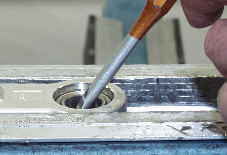
8 Disassemble the rubber cap. Unscrew slowly the nitrogen plug (size 4) to release the pressure. Pay attention to the O-ring of the plug! 8


9 Tap the cap from the tube. Push the adaptor DU-bush downwards. 9 Disassemble the springring out of the groove of the tube.


10 Remove the springring. 1. Pull carefully but firmly the piston rod cpl out of the tube

11 Drain the oil out of the tube. 11


.")
12 Disassembly piston rod Place the piston rod cpl in the vice. Unscrew the piston rod nut (size 17). 12 Turn off the nut.


13 1. Place a screwdriver on top of the piston rod and lift the entire assembly onto the screwdriver. 2. Pay attention to the assembling direction of all the parts!!! 13 Remove the adaptor DU-bush


14 Remove the cap. Remove the bumrubber. Pay attention to the assembling direction! 14 Clamp the mounting-eye in the vice.


15 Unscrew the screw cap out of the mounting-eye with T1218. Turn the screw cap with the adjustment adaptor out of the mounting-eye. 15 Turn the adjustment needle out of the mounting-eye.


16 Tap with T120 the adaptor bush out of the heim joint. Remove the seal. 16 Tap the other adaptor bush out of the heim joint.


17 Push with T1207S the heim joint against the springring of the mounting-eye. Disassemble the springring. 17 Push with T1207S the heim joint out of the mounting-eye. Disassemble when necessary the other springring.


18 Heat the lock nut of the piston rod / mounting-eye. 1. Unscrew the locking nut (size 14)


19 Clamp the piston rod in T1202S. Heat the mounting-eye. 19 Unscrew the mounting-eye.


20 Turn the mounting-eye of the piston-rod. Turn the lock nut of the piston-rod. Pay attention to the assembling direction! 20


21 1. Take the rebound adjustment needle with guiding out of the piston-rod Turn the piston-rod in the clamping block.

. 22 Srew the tap of")
22 Heat the tap of the piston-rod. Untighten the tap (size 15). 22 Srew the tap of the piston-rod.


23 Assembling the piston-rod. Wet the thread of the tap with T132. Screw the tap into the piston-rod. 23 Tighten the tap.

 with T158. 24 1.")
24 Rebound adjustment needle with the needle guiding. Grease both O-rings (in- and outside) with T Place the needle into the piston-rod.


25 2. Screw the lock nut on the piston-rod. 25 Wet the thread of the mounting-eye with T132.


26 Tight the mounting-eye. Tight the lock nut Replace the rebound adjustment needle.


27 2. Screw the needle several turns into the mounting-eye. 27 Greas the adaptor with waterproof grease T159. Replace the rebound screw cap with the adjustment adjuster.


28 Tight the screw cap with T1218. Turn the rebound position fully open. 28 Push the rebound needle downwards.


29 Wet the innerside of the mounting eye a little bit with T132. Assemble one springring into the mounting-eye. 29 Heim joint KGW Pay attention to the bevelled edge on one side!


30 Press with T1207S the heim jont into the mounting eye, with the bevelled edge in the direction of the springring. Assemble the other springring. 30 Replace both seals.


31 Assemble one adaptor bush in the heim joint wit support of T1206. Press the adaptor bush in the heim joint. The second adaptor bush without support of T


32 Replace the bumprubber. Replace the cap. 32


33 Disassembly adaptor DUbush Lift the rebound rubber out of the adaptor. Remove the steel plate. 33 Remove the first back-up ring.


34 Remove the quad-ring. Remove the second back-up ring. 34 Lift the dirt scraper out of the adaptor.


35 Remove the O-ring Press the DU-bush out of the adaptor with T1209 and T Adaptor DU-bush in parts.


36 Assembling adaptor DU-bush Press the DU-bush into the adaptor with T1209 and T1504. Calibrate the DU-bush with the calibration thorn T1205. Important: wet the thorn with oil before the calibration. 36 Press the dirt scraper into the adaptor with assembling bush T1204.
.")

37 Grease the Groove of the adaptor with T158 and assemble the O-ring (not on picture). Replace the second back-up ring. Replace the quad-ring. 37 Replace the first back-up ring.


38 Replace the steel plate. Assemble the rebound rubber in the adaptor DU-bush and ensure that the rubber can rotate in the adaptor. 38 Replace carefully the adaptor DU-bush on the piston-rod.
 - Main piston 1 (with ring and O-ring) -")
 - Piston 2 - Rebound")

39 - Rebound bush plane - Compression setting 1 (shims) - Main piston 1 (with ring and O-ring) - Rebound setting 1 (shims) - Intermediate bush) - Compession setting 2 (shims) - Piston 2 - Rebound check valve setting - Piston-rod nut Assemble the rebound bush plane. 39 Assemble compression shim setting 1.


40 Replace piston 1. Assemble rebound setting Replace the intermediate bush.


41 Assemble compression setting 2. Replace piston Assemble the ring of check-valve setting 2.


42 Assemble the shim of check-valve setting over the ring 2. Assemble the shim. 42 Turn the nut on the piston-rod,

43 Tighten the piston-rod nut to a torque of 30Nm. 43


44 Disassembly tube side Turn the screw retainer of the tube. Untighten the screw cap of the DCC (Duel Compression Control) of the bottom. (size 24) 44 Remove the screw cap.


45 Pull the DCC out of the bottom. DCC 45 Unscrew and remove the plug R1/8.


46 Heat the lock ring of the tube/bottom. Untighten the lock ring with a open spanner. 46 Remove the caution sticker.


47 Heat the bottom near the tube. Untighten the tube with slide spanner T146 with bush T Turn the tube out of the bottom.


48 Pull the hydraulic sleeve out of the bottom. Disassemble the O-ring. 48


49 Remove the sticker. Heat the reservoir near the bottom. 49 Use T125S and T145S...


50 ...to untighten the reservoir. Unscrew the reservoir of the bottom. 50 Remove the O-ring.

 Clamp slide spanner T146")

51 - Bottom - Both O-rings - Hydraulic sleeve To disassemble the adaptor bushes and heim joint see disassembly piston rod (mounting-eye) Clamp slide spanner T146 with bush T148 in the vice, see picture. Heat the lock ring. 51 Screw the lock ring of the tube.


52 Tube with lock ring. Pay attention to the assembling direction! Push with T170S the separation piston ot of the reservoir. 52 Remove the O-ring and piston ring.

53 - Reservoir - O-ring - Piston ring - Separation piston 53


54 Assembling tube side Grease the groove of the separation piston with T158. Assemble the O-ring and grease the O-ring with T Grease the surface of the inner side of the reservoir with T158.


55 1. Assemble the separation piston with piston ring with the hollow surface into the reservoir. 2. Push the separation piston into the reservoir. 55


56 1. Assemble both O-rings Wet the thread of the bottom and the thread of the reservoir with T131.


57 Screw the reservoir on the bottom. Tighten the reservoir with T125S and T145S. 57 Screw the lock ring on the tube as far as possible.


58 Assemble the hydraulic sleeve. Wet the thread of the tube with T Grease the edge of the tube a little bit with T158.


59 Screw the retainer into the bottom. Tighten the tube. 59 Screw the lock ring downwards against the bottom.


60 Tighten the lock ring with the hook spanner. Place a new caution sticker. 60


61 Gease the O-ring of the DCC piston. Assemble the DCC into the bottom. 61 Place the spring.


62 Grease the O-ring inside of the hexagonal with T158. Srew the screw cap of the DCC into the bottom. 62 Tighten the screw cap to a torque of 50Nm.


63 Screw the filling plug R1/8 in the bottom and tighten it to a torque of 16Nm. Fill the tube with oil till about 50mm under the spring ring groove. 63 Adjust the O-ring of T170S like picture (± 50mm of the top).


64 Push the separation piston fully downwards. Use plunger T110S to push the oil through the bottom.


65 Push T170S again fully downwards. Fill the tube with oil till ± 10mm under the spring ring groove. 65 Slide the piston rod side cpl in the oil.


66 Assemble the adaptor DU-bush in the oil and......push the adaptor just under the spring ring groove. 66 Assemble first the closed side of the spring ring into the groove and then the open side.


67 Pull the piston rod cpl fully out. Tap the cap into the tube. 67


68 Bleeding Disassemble the DCC. Place the schock absorber in the vice like picture - not too tight. Turn adaptor T1502S of the air release bottle T144S into the (DCC) housing of the bottom Hold the bottle up so that the oil will flow into the shock absorber.


69 2. 3. Push slowly the pison rod inside Pull the piston rod completely out.


70 5. Cant the shock absorber several times. Repeat handling 1until 5 till all air is out of the shock absorber. Push the separation piston with T170S till the distance between the screw cap of the reservoir is 10mm. Remove the adaptor and replace the DCC. 70


71 Place the screw retainer. Place a new sticker. 71

.")

72 On pressure with nitrogen Screw the nitrogen plug with O-ring several turns into the screw cap. Use nitrogen charging device T170S1 for filling the shock absorber with nitrogen (10 BAR). 72 Place the shock absorber in T170S1 and open the tap for about 20 seconds. Close the nitrogen plug. Close the tap.

73 Replace the rubber do not open cap. 73


74 Mounting spring assemble the washer. Assemble the spring. 74 Assemble the second washer.


75 Assemble the open spring retainer. Adjust the spring to the correct preload as measured before. 75 Important! Tighten the Allen bolt of the spring retainer to a torque of 5Nm.


76 Adjustments Compression position low-speed! Compression position high-speed! 76 Rebound position!
Workshop manual 5018 PDS Product Exploded View Disassembly & Assembling. Shock absorber 5018 PDS OEM Shock absorber 5018 PDS /2002
 Shock absorber 5018 PDS OEM 2000 Introduction 2 Exploded view 3 Disassembly shock absorber 4 Disassembly piston-rod 11 Disassembly adaptor DU-bush 15 Assembling adaptor DU-bush 17 Assembling piston-rod
Workshop manual 3612 / 4681 BAVP. Product Exploded View Disassembly & Assembling. Shock absorber
 455 Shock absorber 3612/4681 BAVP 02/2002 Shock absorber Introduction 2 Exploded view 3 Adjustment 4 Disassembly shock absorber 5 Disassembly piston-rod 7 Disassembly adaptor DU-bush 15 Disassembly tube
4357 / 4860 MX Multi Adjuster
 12_234 Frontfork 4357 / 4860 MX Multi Adjuster Introduction 2 Exploded view 3 Disassembly forkleg 4 Disassembly screw-cap 15 Assembling screw-cap 17 Disassembly cartridge 18 Disassembly compression holder
Sachs shock manual. ( ) 2 & 4 Stroke RR Enduro. ( ) RS Dual Sport
 2 & 4 Stroke RR Enduro. ( ) RS Dual Sport") Sachs shock manual (2013 2015) 2 & 4 Stroke RR Enduro (2014-2015) RS Dual Sport 1 Introduction The procedures in this manual must take place in a clean environment using professional tools and some specific,
Sachs shock manual (2013 2015) 2 & 4 Stroke RR Enduro (2014-2015) RS Dual Sport 1 Introduction The procedures in this manual must take place in a clean environment using professional tools and some specific,
Shock absorber for Automotive TTX36 P/ IL. Workshop Manual
 TTX6P TTX6IL Shock absorber for Automotive TTX6 P/ IL Workshop Manual Safety precautions General Warnings Note! The shock absorber/front fork/steering damper is an important part of the vehicle and will
REPAIRMANUAL
 REPAIRMANUAL2005-2007 WP SHOCK ABSORBER 5018 DCC 5018 SXS 5018 SMR REPARATURANLEITUNG MANUALE DI RIPARAZIONE MANUEL DE RÉPARATION MANUAL DE REPARACIÓN ART.NO.: 3.211.208-E 1 SPECIAL TOOLS 2 GENERAL INFORMATION
Super T QR20 INSTRUCTIONS GENERAL RULES
 INSTRUCTIONS GENERAL RULES 1. Where specified, assemble and disassemble the shock absorption system using the MARZOCCHI special tools only. 2. On reassembling the suspension system, always use new seals.
Shock Absorber for Formula Student and Formula SAE TTX 25. Workshop Manual
 Shock Absorber for Formula Student and Formula SAE TTX 5 Workshop Manual SAFETY PRECAUTIONS General Warnings Note! The shock absorber is an important part of the vehicle and will affect the stability.
Owners manual Competition Shock absorber. WP Suspension Netherlands
 Owners manual 4618 Competition Shock absorber WP Suspension Netherlands 1 INTRODUCTION: Congratulations on your purchase of this WP Suspension shock absorber, The shock absorber that won the 2001/2002/2003/2004/2005/2006
Sachs 48mm Closed Cartridge fork Service Manual
 Sachs 48mm Closed Cartridge fork Service Manual 1 Fork seal driver 2 Special soft jaws 3 Fork cap wrench 4 Rebound rod holding tool 5 Compression assembly holding tool 6 Retaining clip tool Special Tools
Front Fork Disassembling and Assembling RM-Z250L6. KAYABA Pneumatic Spring Front Fork PSF2
 Front Fork Disassembling and Assembling RM-Z250L6 KAYABA Pneumatic Spring Front Fork PSF2 RM-Z250L6 Front Fork Disassembling 1. Release air Release the air pressure by pressing the air valve with a screwdriver.
Repair Manual and Spare Parts List
 Pneumatic Drive Unit Type Techn. Doc. No. 352 and Accessories for Pipe Cutting Machine Darstellung kann vom Original abweichen Repair Manual and 580027000_Inst_en_Version_02 Repair General In general,
Z1 Free Ride INSTRUCTIONS GENERAL RULES
 INSTRUCTIONS GENERAL RULES 1. Where specified, assemble and disassemble the shock absorption system using the MARZOCCHI special tools only, as shown in the table below. 2. On reassembling the suspension
TOPAZ Service Guide. Full Service
 TOPAZ Service Guide Full Service SERVICE OVERVIEW This manual will guide you step by step performing an air service to your Topaz. Please follow each instruction carefully to achieve the best and safest
Öhlins Front Fork for. Motocross and Enduro. Owner s Manual
 Öhlins Front Fork for Motocross and Enduro Owner s Manual Safety Precautions The front fork is a very important part of the vehicle and will therefore affect the stability. Read and make sure that you
10A 10F 10B 10E 10A 10D 10B. Mr. T 10C Q R
 Q R 2 0 23 30 12 18 17 16 15 14 37 39 38 3 7 6 5 20 26 21 22 40 13 4 2 25 24 8 1 28 27 11 31 19 10A 10D 10B 10C 10 29 10A 10F 10B 10E 10 9 32 36 33 34 35 178 15 GENERAL 82 80 Ø28.6 ±0.1 Ø30 +0.05 0 348
FITTING INSTRUCTIONS YAMAHA YZF-R3
 FITTING INSTRUCTIONS YAMAHA YZF-R3 120-015-270-005 20/07/2017 ISSUE 1 2 IMPORTANT NOTES KEY NB NOTE! CAUTION! WARNING! NB NB NB The front forks are a very important part of the motorcycle and will affect
X-Trainer 43mm fork service manual. Beta USA, Inc This work should be performed by a trained motorcycle technician.
 X-Trainer 43mm fork service manual Beta USA, Inc. 2016 This work should be performed by a trained motorcycle technician. Table of contents Page Introduction/special tools... 2 Fork exploded view... 3 Legend.
BM 048 BMW F 650 GS Dakar
 Öhlins shock absorber 46 HRCS Your Öhlins shock absorber type 46 HRCS features the following adjusters: Compression damping adjuster Adjustments are made on top of the reservoir. Rebound damping adjuster
Contents. 1.2 Cartridge maintenance Replacement of the cartridge gasket Piston segment replacement Piston replacement 20
 KAYABA SUSPENSION Contents KAYABA SUSPENSIONS General remarks 3 1- YOKE Exploded view 4 1.1 Maintenance of Gaskets and Rings 1.1.1 Disassembly 5 1.1.2 Assembly 8 1.2 Cartridge maintenance 1.2.1 Replacement
SU 201 Suzuki V-storm 1000
 Öhlins shock absorber 46 PRCS Your Öhlins shock absorber type 46 PRCS features the following adjusters: Compression damping adjuster (C) Adjustments are made on top of the reservoir. Rebound damping adjuster
OVERHAUL. Remove the union bolt and a gasket from the disc brake cylinder, then disconnect the flexible hose from the disc brake cylinder.
 OVERHAUL COMPONENTS: See page 3232 Overhaul the RH side by the same procedures with LH side. Two types of brake pad exist; one is with slit and the other without slit. 1. REMOVE REAR WHEEL 2. DRAIN FLUID
Jr. T GENERAL. BAM: Bomber Aerospace Material. Special alloy extracted from aerospace material. Ø TRAVEL ±
 175 15 GENERAL The double clamp fork is specifically designed for Downhill use. The fork is sprung by a mechanical spring and uses hydraulic rebound damping. Spring pre-load adjustment controlled via external
Shock Absorber Rebuild Manual
 Shock Absorber Rebuild Manual Model PODIUM RC3 FOX RACING SHOX 130 Hangar Way, Watsonville, CA 95076 PHONE 800.369.7469 FAX 831.768.7026 Email: psservicemw@ridefox.com Website: www.ridefox.com Disclaimer
Double Barrel Service Instructions Cane Creek R&D. January 2009 V2.0 1
 Double Barrel Service Instructions Cane Creek R&D January 2009 V2.0 1 Table of Contents 3. Diagnosis for Parts Needed 4. Work Flow 5. Initial Disassembly 6. Initial Disassembly Pictures 8. Reservoir Rebuild
Maverick American 3085 Bluff Street Boulder, CO Tel: Fax: ML7.0 SHOCK SERVICE MANUAL
 Maverick American 3085 Bluff Street Boulder, CO 80301 Tel: 303-415-0370 Fax: 303-415-0676 www.maverickamerican.com ML7.0 SHOCK SERVICE MANUAL 1. OVERVIEW 1.1. The Maverick ML7.0 rear shock is an oil damped
Z1 Free Ride (110) GENERAL
 GENERAL") GENERAL (110) 175 80 Ø 30 +0.05 0 L.MAX=493 L.L.=483 ±2 L.MIN=373 426 ±2 57 CORSA 110 TRAVEL 110 18 Ø 30 15 20 0-0.1 +1 0 248.5 Special ride and Downhill fork whose legs are damped by a spiral springs
GENERAL (110) 175 80 Ø 30 +0.05 0 L.MAX=493 L.L.=483 ±2 L.MIN=373 426 ±2 57 CORSA 110 TRAVEL 110 18 Ø 30 15 20 0-0.1 +1 0 248.5 Special ride and Downhill fork whose legs are damped by a spiral springs
FRONT BRAKE COMPONENTS
 BR18 BRAKE SYSTEM FRONT BRAKE COMPONENTS REPLACEMENT OF BRAKE PADS HINT: If a squealing noise occurs from the front brakes while driving, check the pad wear indicator. If there are traces of the indicator
BM 318. BMW K1200, rear. Öhlins shock adsorber 46 HRCLS CAUTION! Your Öhlins shock absorber type 46 HRCLS features the following adjusters:
 Öhlins shock adsorber 46 HRCLS Your Öhlins shock absorber type 46 HRCLS features the following adjusters: Rebound damping adjuster (R) Adjuster wheel on the piston shaft above the end bracket. Compression
Marzocchi Suspension Drop-Off SL Drop-Off SL. Technical instructions. Technical characteristics: Technical characteristics
 Technical instructions Technical characteristics: Technical characteristics Single-crown fork with ø 32mm legs. Available travels: 130mm, 150 mm. Right fork leg damping element: spring (air pre-load).
Disassembly. 1 Pull off the QUIK-LOK cable from the machine.
 Special Tools Require Important! Torx TX0 bit 0 0 Screwdriver Torx 0 0 0 Forcing Discs 0 Before beginning the maintenance work, perform an initial check with a high voltage test according to VDE (see chapter
Maverick American 3085 Bluff Street Boulder, CO Tel: Fax: ML7.2 SHOCK SERVICE MANUAL
 Maverick American 3085 Bluff Street Boulder, CO 80301 Tel: 303-415-0370 Fax: 303-415-0676 www.maverickamerican.com ML7.2 SHOCK SERVICE MANUAL 1. OVERVIEW 1.1. The Maverick ML7.2 rear shock is an oil damped
Z5 Coil (80) GENERAL. BAM: Bomber Aerospace Material. Special alloy developed from aerospace material. Ø TRAVEL 80 55
 GENERAL. BAM: Bomber Aerospace Material. Special alloy developed from aerospace material. Ø TRAVEL 80 55") (8) 175 8 Ø3 +.5 L.MAX=461 L.L.=451 L.MIN=371 ±2 396 ±2 TRAVEL 8 55 18 Ø3 15 2 -.1 +1 248.5 GENERAL The fork is sprung by a mechanical coil system and uses hydraulic rebound damping. Spring pre-load adjustment
(8) 175 8 Ø3 +.5 L.MAX=461 L.L.=451 L.MIN=371 ±2 396 ±2 TRAVEL 8 55 18 Ø3 15 2 -.1 +1 248.5 GENERAL The fork is sprung by a mechanical coil system and uses hydraulic rebound damping. Spring pre-load adjustment
Öhlins Front Fork Superbike FGR 900. Owner s Manual
 Öhlins Front Fork Superbike FGR 900 Owner s Manual Introduction Öhlins Racing AB - The Story It was the 1970 s, a young man named Kenth Öhlin spent most of his spare time pursuing his favourite sport:
Ducati 899/959 Panigale (Showa) FKR Spare Parts List Workshop Manual
 FKR Spare Parts List Workshop Manual") Ducati 899/99 Panigale (Showa) FKR 11 0 Spare Parts List Workshop Manual SAFETY PRECAUTIONS The shock absorber/front fork/steering damper is an important part of the vehicle and will affect the stability.
Ducati 899/99 Panigale (Showa) FKR 11 0 Spare Parts List Workshop Manual SAFETY PRECAUTIONS The shock absorber/front fork/steering damper is an important part of the vehicle and will affect the stability.
Shock Absorber TTX39 for BMW R1200GS Rear BM Spare Parts List
 Shock Absorber TTX39 for BMW R1200GS Rear BM 6760 Spare Parts List Safety Precautions Note! The shock absorber is a very important part of the vehicle and will therefore affect the stability of the vehicle.
Marzocchi Suspension D-Street 24" D-Street 24" Technical instructions
 Technical instructions Exploded view - D-Street 24" 80 Rif. Code Quantity D-Street 24" 80 - Oil levels Position Oil type Quantity (cc) Right fork leg SAE 7,5-550013 185 Left fork leg SAE 7,5-550013 185
Super T QR20 GENERAL. BAM: Bomber Aerospace Material. Special alloy extracted from aerospace material Ø30 +0.
 175 15 GENERAL 80 Ø30 +0.05 0 L.MAX=726.8 L.L.=716.8 L.MIN=566.8 ±2 273 ±2 523 193.8 RAVEL 150 49 35 15 20 0-0.1 +1 0 248.5 he double clamp fork is specifically designed for Downhill use. he fork is damped
Owners Manual Öhlins shock absorbers, Car Rally & Track
 Owners Manual Öhlins shock absorbers, Car Rally & Track Including: How the shocks works Setting up the car Making adjustments Trouble shooting Maintenance Inspection 1 2 Safety signals Important information
Replace brake pads and discs - rear * (Volkswagen Golf )
") Replace brake pads and discs - rear * (Volkswagen Golf 1997-2004) *Caution! This instructions are created by random users and must be used as a reference only! Please, take all safety precautions, and
Replace brake pads and discs - rear * (Volkswagen Golf 1997-2004) *Caution! This instructions are created by random users and must be used as a reference only! Please, take all safety precautions, and
ARTICLE BEGINNING DESCRIPTION ADJUSTMENTS & INSPECTION SUSPENSION Rear. Golf III
 Article Text ARTICLE BEGINNING 1995-96 SUSPENSION Rear Golf III DESCRIPTION Suspension uses control arms and axle beam for stabilization. Control arms and axle beam are combined as one unit. Brake drums
1993 SUSPENSION Volkswagen Rear. EuroVan
 Article Text ARTICLE BEGINNING 1993 SUSPENSION Volkswagen Rear EuroVan DESCRIPTION Suspension uses control arms and axle beam for stabilization. Control arms and axle beam are combined as one unit. Brake
Repair Manual and Spare Parts List
 Hydraulic Drive Unit Type Techn. Doc. No. 362 and Accessories for Pipe Cutting Machine Darstellung kann vom Original abweichen Repair Manual and 580067000_Inst_en_Version_03 Repair General In general,
INSTRUCTIONS Servicing PAH
 INSTRUCTIONS Servicing PAH 10-12.5 180R9095 Note: Dismantling: If the pump is dismantled during the warranty period, the pump is no longer under warranty. 180R9095 1. Tools required for dismantling the
manual Shock 03_ A5 _E :39 Uhr Seite 2 CONTENT
 manual Shock 03_ A5 _E 17.06.2004 12:39 Uhr Seite 2 CONTENT > Traction Control-Functions P. 02 > Picture of the Genius Shock and Remote Control Lever P. 03 > Basic Set-Up of the Remote Control P. 04 >
«SAG-BOY» BIKE OWNERS MANUAL OWNERS MANUAL BEDIENUNGSANLEITUNG MANUEL D UTILISATION
 «SAG-BOY» OWNERS MANUAL BEDIENUNGSANLEITUNG MANUEL D UTILISATION The length of the grey beam shows the optimum eye-to-eye distance of the rear shocks. Der graue Balken zeigt den optimalen Bolzenabstand
Owners manual. Öhlins Superbike front fork FG 170
 Owners manual Öhlins Superbike front fork FG 0 Including: Setting up your fork Changing springs and seals Service the fork Trouble shooting Technical info Spare parts & tools Öhlins super bike front fork
Built for winners
 www.wp-group.com Built for winners TABLE OF CONTENTS 2 TABLE OF CONTENTS 1 FORK, TRIPLE CLAMP... 3 1.1 Performing a fork service... 3 1.2 Disassembling the fork legs... 3 1.3 Removing the spring... 5 1.4
FRONT BRAKE COMPONENTS
 BR18 COMPONENTS BRAKE PADS REPLACEMENT HINT: If a squealing noise occurs from the brakes while driving, check the pad wear indicator plate. If the pad wear indicator plate contacts the disc, the brake
KIT 10 10A 10D 10B 10C Z1 Q R 10A 10F 10B 10E
 11 9 1 13 3 17 18 16 9 3 3 4 5 6 7 8 8 1 14 15 7 19 6 5 4 3 33 31 1 37 13 1 1E 1B 1F 1A 1 9 36 34 35 1 1A 1D 1B 1C 38 KIT 178 15 GENEAL 8 8 348 L.MAX=51.6 L.L.=5.6 L.MIN=37.6 ± ± 44.1 TAVEL 13 58.5 1 Ø3
TRIM AND TILT TABLE OF CONTENTS TRIM AND TILT
 TRIM AND TILT TABLE OF CONTENTS SERVICE CHART................................................................... 326 SYSTEM DESCRIPTION............................................................. 328
SCOTT BICYCLES OWNERS MANUAL Content
 manual Shock 03_ A5 _E 30.09.2003 14:59 Uhr Seite 2 SCOTT BICYCLES The basic set-up of the Scott Genius Shock is easy and can be done within a few minutes. The Scott Genius Shock should be adjusted exactly
Level 1 and Level 2/3 Fork Upgrade Fitting Instructions
 Fitting Instructions for Honda CB500X/F Level 1 and Level 2/3 Fork Upgrade Fitting Instructions Ensure bike is securely mounted on suitable stand or scissor lift, if our Engine Guard RRP 437, is fitted.
Servicing front brakes
 46-1 Servicing front brakes C54 brake caliper, servicing Special tools and workshop equipment required VAG 1331 Torque wrench (or equivalent) VAG 1410 Torque wrench (or equivalent) VAG 1869/2 Brake pedal
Marzocchi Suspension Drop-Off IV Drop-Off IV. Technical instructions
 Technical instructions Exploded view - Drop-Off IV - 110 Rif. Code Quantity Drop-Off IV - 110 - Oil levels Position Oil type Quantity (cc) Right fork leg SAE 7,5-550013 180 Left fork leg SAE 7,5-550013
SERVICE PROCEDURES FOR CLUTCH HYDRAULIC UNITS
 SERVICE PROCEDURES FOR CLUTCH HYDRAULIC UNITS SAFETY PROCEDURES Always follow the vehicle manufacturer's recommended safety procedures in your Shop and Owners Manual. REQUIRED TOOLS Flat blade screwdriver,
Maintenance Information
 16572679 Edition 2 May 2014 Air Drill QP Series Maintenance Information Save These Instructions Product Safety Information WARNING Failure to observe the following warnings, and to avoid these potentially
Maintenance Information
 16575243 Edition 2 October 2013 Air Screwdrivers 1R Series Maintenance Information Save These Instructions Product Safety Information WARNING Failure to observe the following warnings, and to avoid these
X-FLY (80) GENERAL. BAM: Bomber Aerospace Material. Special alloy developed from aerospace material. Ø TRAVEL Ø30
 GENERAL. BAM: Bomber Aerospace Material. Special alloy developed from aerospace material. Ø TRAVEL Ø30") (8) 175 8 Ø3 +.5 L.MAX=461 L.L.=451 L.MIN=371 ±2 396 ±2 TRAVEL 8 55 18 Ø3 15 2 -.1 +1 248.5 GENERAL Special air/oil damped cross-country fork: each leg uses pressurized air blown through a special valve
(8) 175 8 Ø3 +.5 L.MAX=461 L.L.=451 L.MIN=371 ±2 396 ±2 TRAVEL 8 55 18 Ø3 15 2 -.1 +1 248.5 GENERAL Special air/oil damped cross-country fork: each leg uses pressurized air blown through a special valve
Spare Parts List. BU TTX 36 Buell 1125 CR
 Spare Parts List BU 888 - TTX 36 Buell 1125 CR SPARE PARTS LIST BU 888 - TTX 36 Safety Precautions Note! The shock absorber is a very important part of the vehicle and will therefore affect the stability
MAINTENANCE PROCEDURE FOR MK21
 MAINTENANCE PROCEDURE FOR MK21-1 - MAINTENANCE PROCEDURE FOR MK 21 1 ST STAGE WARNING: this maintenance procedure is only for appointed Scubapro technicians that followed a complete course on equipment
Shock Absorber TTX44 for Honda CRF 150R HO Spare Parts List
 Shock Absorber TTX for Honda CRF 0R HO 990 Spare Parts List Safety Precautions Note! The shock absorber is a very important part of the vehicle and will therefore affect the stability of the vehicle. Read
Shock Absorber Rebuild Manual
 Shock Absorber Rebuild Manual Model PODIUM X FOX RACING SHOX 130 Hangar Way, Watsonville, CA 95076 PHONE 800.369.7469 ext. 7647 FAX 831.768.7026 Email: info@foxracingshox.com Website: www.foxracingshox.com
PAH, PAHT, PAHT G pumps PAH , PAHT and PAHT G Disassembling and assembling
 Servie guide PAH, PAHT, PAHT G pumps PAH 10-12.5, PAHT 10-12.5 and PAHT G 10-12.5 Disassembling and assembling hpp.danfoss.com Table of Contents 1. Disassembling the pump...3 2. Inspection...7 2.1. Port
Z3 Coil (80) GENERAL. BAM: Bomber Aerospace Material. Special alloy developed from aerospace material. Ø TRAVEL 80 55
 GENERAL. BAM: Bomber Aerospace Material. Special alloy developed from aerospace material. Ø TRAVEL 80 55") (8) 175 8 Ø3 +.5 L.MAX=461 L.L.=451 L.MIN=371 ±2 396 TRAVEL 8 55 18 Ø3 15 2 -.1 +1 248.5 GENERAL The fork is sprung by a mechanical coil system and uses hydraulic rebound damping. Spring pre-load adjustment
(8) 175 8 Ø3 +.5 L.MAX=461 L.L.=451 L.MIN=371 ±2 396 TRAVEL 8 55 18 Ø3 15 2 -.1 +1 248.5 GENERAL The fork is sprung by a mechanical coil system and uses hydraulic rebound damping. Spring pre-load adjustment
Z3 QR20 (110) GENERAL
 GENERAL") (11) 175 18 8 Ø3 +.5 L.MAX=491 L.L.=481 ±2 L.MIN=371 426 55 ±2 TRAVEL 11 Ø3 15 2 -.1 +1 248.5 GENERAL The fork is sprung by a mechanical coil system and uses hydraulic rebound damping. Spring pre-load
(11) 175 18 8 Ø3 +.5 L.MAX=491 L.L.=481 ±2 L.MIN=371 426 55 ±2 TRAVEL 11 Ø3 15 2 -.1 +1 248.5 GENERAL The fork is sprung by a mechanical coil system and uses hydraulic rebound damping. Spring pre-load
Repair Manual VW 02J gearbox. INA GearBOX
 Repair Manual VW 02J gearbox INA GearBOX Special tools Pipe section, 50 mm: Press fitting of synchronizer body for third/fourth gear. Assembly of support bearing for input and output shaft. Part number:
TTX30 KTM 50SX KT Spare Parts List
 TTX30 KTM 50SX KT 397 Spare Parts List Safety Precautions General Warnings The shock absorber/front fork/steering damper is an important part of the vehicle and will affect the stability. Safety Symbols
Marzocchi Suspension AM SL / TW AM SL / TW. Technical instructions
 Technical instructions Spare part list - AM SL / TW 130 Rif. Code Description Q.ty in the model Technical characteristics: Technical characteristics Single-crown fork with ø 32mm legs. Available travels:
Work shop manual. Öhlins Steering damper Road & Track
 Work shop manual Öhlins Steering damper Road & Track Including: Introduction Safety instructions Dismantling the steering damper Assembling the steering damper Filling oil Introduction All of Öhlins advanced
Maintenance Information
 45530136 Edition 1 July 2008 Electric Screwdrivers EL 24V DC Series Maintenance Information Save These Instructions WARNING Always wear eye protection when operating or performing maintenance on this tool.
FOX Racing Shox Bypass Technical Manual.
 FOX Racing Shox Bypass Technical Manual. The following technical manual will be using a 2.5 dia. shock with three tubes for descriptions and illustrations. Your shock may differ in the number of tubes,
INSTALLATION INSTRUCTIONS MKIV Toyota Supra Manual Rack Conversion
 INSTALLATION INSTRUCTIONS MKIV Toyota Supra Manual Rack Conversion 1 Removal of Stock Rack 1.1 With your steering wheel centered, remove the pinch bolt from the factory intermediate shaft. This is located
Hydraulic Reciprocating Saw
 Hydraulic Reciprocating Saw Type 5 1220 0050 Darstellung kann vom Original abweichen Repair Manual and Spare Parts List Compiled: 29.04.11 www.csunitec.com Page 1 of 16 REPAIR INSTRUCTION Do not disassemble
KIT 8 9 9A Q R 15A 15B. yyy
 ,,,,, yy yyy 3 8 9 9A 6 7 6A 5 3 3 1 11 1 13 14 34 15A 15B 15 16 17 4 5 3 8 6 7 9 31 1 18 19 1 33 4 41 35 39 38 37 36 4 KIT 178 8 8 348 ± L.MAX=51.5 L.L.=5.5 L.MIN=37.5 ± 44 58.5 TAVEL 13 15 1 Ø3 43 48.5
Features. Marathon SL TECHNICAL CHARACTERISTICS. Sliding bushes: made of friction free and wear free material.
 Features TECHNICAL CHARACTERISTICS Fork with Ø30 mm legs with "Double Air" damping system. Adjustment of the air preload (positive air) on both legs. Adjustment of the rebound damping (negative air) on
Replace clutch and flywheel * (Volkswagen Sharan 2010-Present)
") Replace clutch and flywheel * (Volkswagen Sharan 2010-Present) *Caution! This instructions are created by random users and must be used as a reference only! Please, take all safety precautions, and if
Replace clutch and flywheel * (Volkswagen Sharan 2010-Present) *Caution! This instructions are created by random users and must be used as a reference only! Please, take all safety precautions, and if
WESCO INDUSTRIAL PRODUCTS, INC. Manual Non Telescoping High Lift Truck. Part Number: &
 WESCO INDUSTRIAL PRODUCTS, INC Manual Non Telescoping High Lift Truck Part Number: 272462 & 272463 Note: Operator MUST read and understand these operating instructions before using this Truck. TABLE OF
S USP E N S I O N I N N O VAT I O N F I F T Y Y E A RS O F CE 1949 SINCE 1949 SINCE 1949
 S USP E N S I O N I N N O VAT I O N F I F T Y Y E A RS O F CE 199 SINCE 199 SINCE 199 INDEX Page OWNER S INFORMATION... 2 GENERAL SPECIFICATIONS... 3 GENERAL RULES FOR A CORRECT OVERHAULING AND MAINTENANCE...
FORK G2-R COMPRESSION GOLD VALVE INSTALLATION - DIRT 37
 1501 Pomona Rd, Corona, CA 92880 951.279.6655 fax 951.279.7171 racetech.com FORK G2-R COMPRESSION GOLD VALVE INSTALLATION - DIRT 37 FK code FMGV 3720G P Thede 12.3.15 TOOLS REQUIRED:
Maintenance Information
 16573321 Edition 3 February 2014 Air Grinder Series 61H Maintenance Information Save These Instructions Product Safety Information WARNING Failure to observe the following warnings, and to avoid these
Maintenance Information
 45761848 Edition 3 February 2014 Air Die Grinder AC4A, SC4A and XC4A Series Maintenance Information Save These Instructions Product Safety Information WARNING Failure to observe the following warnings,
Shock TTX36 EC Ducati Multistrada 1200 S DU Spare Parts List
 Shock TTX EC Ducati Multistrada 00 S DU 00 Spare Parts List Spare Parts List - DU 00 TTX EC Safety Precautions Note! The shock absorber is a very important part of the vehicle and will therefore affect
MAINTENANCE PROCEDURE FOR MK18/MK16
 MAINTENANCE PROCEDURE FOR MK18/MK16 MK16/MK18-1/1- MAINTENANCE PROCEDURE FOR MK 16 / 18 1 ST STAGES WARNING: this maintenance procedure is only for appointed Scubapro technicians that followed a complete
MAXXUS 22. Mechanical Sliding Disc Brake Caliper
 MAXXUS 22 Mechanical Sliding Disc Brake Caliper MAXXUS 22 Mechanical Sliding Disc Brake Caliper Assembly Instructions/ Maintenance Guidelines Edition 1 This publication is not subject to any update service.
Marzocchi Suspension MZ III MZ III. Technical instructions
 Technical instructions Exploded view - MZ III - 100 Rif. Code Quantity Spare part list - MZ III - 100 Rif. Code Description Q.ty in the model Technical characteristics: Technical characteristics Single-crown
Maintenance Information
 04581245 Edition 2 May 2014 Air Grinder, Die Grinder and Sander Series G2 (Angle) Maintenance Information Save These Instructions Product Safety Information WARNING Failure to observe the following warnings,
MAINTENANCE PROCEDURE FOR MK17
 MAINTENANCE PROCEDURE FOR MK17 MK17 25. juli 2005-1/5 MAINTENANCE PROCEDURE FOR MK 17 1ST STAGE WARNING: this maintenance procedure is only for appointed Scubapro technicians that followed a complete course
DISC BRAKE/DUAL MASTER CYLINDER CONVERSION. Tools, Equipment and Supplies Needed:
 Please take the time to read the enclosed instructions carefully. If you have any questions, call our Product Assistance personnel for clarification. It is important to note that these instructions contain
OWNERS MANUAL. LINK & PDS Trax shock absorber.
 OWNERS MANUAL LINK & PDS Trax shock absorber Introduction: Congratulations on your purchase of the WP Trax Off-road shock absorber. The WP Trax shock absorber has a unique system, which provides better
HFB Steering Gear Service Manual
 TRW Automotive Commercial Steering Systems HFB Steering Gear Service Manual HFB64 SERIES Die Cut HFB64 Integral Hydraulic Power Steering Gear This steering gear was specifically designed for motor trucks;
Shock Absorber TTX36 Honda CBR 1000 RR HO Spare Parts List
 Shock Absorber TTX36 Honda CBR 1000 RR HO 9310 Spare Parts List SPARE PARTS LIST HO 9310 - TTX 36 Safety Precautions Note! The shock absorber is a very important part of the vehicle and will therefore
REPAIR INSTRUCTIONS FIRST STAGE REDUCING VALVE
 REPAIR INSTRUCTIONS REDUCING VALVE EXPLODED VIEW Art. No. 2801, 2808, 2962, 3257, 3580, 3585 JETSTREAM - YOKE 5000 - YOKE ANTI-FREEZE CUP DIFFERENT CONNECTION SECONDARY PART PRIMARY PART BALANCING PART
Shock Absorber Triumph Speed Triple 1050 TR Spare Parts List
 Shock Absorber Triumph Speed Triple 00 TR 00 Spare Parts List Safety Precautions Note! The shock absorber is a very important part of the vehicle and will therefore affect the stability of the vehicle.
SR 55 POWER STEERING GEAR. POWER STEERING GEAR REMOVAL AND INSTALLATION Remove and install the parts, as shown.
 STEERING SR55 GEAR GEAR REMOVAL AND INSTALLATION Remove and install the parts, as shown. SR56 STEERING MAIN POINT OF REMOVAL AND INSTALLATION 1. REMOVE OIL RESERVOIR 2. REMOVE AIR CLEANER ASSEMBLY 3. DISCONNECT
Z3 Air (80) GENERAL. BAM: Bomber Aerospace Material. Special alloy developed from aerospace material. Ø TRAVEL 80 L.MAX=461 L.L.=451 L.
 GENERAL. BAM: Bomber Aerospace Material. Special alloy developed from aerospace material. Ø TRAVEL 80 L.MAX=461 L.L.=451 L.") (80) 175 18 80 Ø30 +0.05 0 55 L.MAX=461 L.L.=451 L.MIN=371 396 ±0,1 TRAVEL 80 ±2 Ø30 15 20 0-0.1 +1 0 248 GENERAL Special air/oil damped cross-country fork: each leg uses pressurized air blown through
(80) 175 18 80 Ø30 +0.05 0 55 L.MAX=461 L.L.=451 L.MIN=371 396 ±0,1 TRAVEL 80 ±2 Ø30 15 20 0-0.1 +1 0 248 GENERAL Special air/oil damped cross-country fork: each leg uses pressurized air blown through
Marzocchi Suspension MZ I MZ I. Technical instructions
 Technical instructions Exploded view - MZ I - 100 Rif. Code Quantity Spare part list - MZ I - 100 Rif. Code Description Q.ty in the model Technical characteristics: Technical characteristics Single-crown
BMS MI40. Shock absorber Kit for BMW M3 (E90, E92) - front. Mounting Instructions
 - front. Mounting Instructions") Kit Contents Description Pcs Strut Dust boot Nut M14 Spacer Mounted on shock absorber Sleeve 1 Used for front and rear C-spanner 1 C-spanner 1 Öhlins sticker 1 Öhlins Owner s Manual 1 Please note that
Kit Contents Description Pcs Strut Dust boot Nut M14 Spacer Mounted on shock absorber Sleeve 1 Used for front and rear C-spanner 1 C-spanner 1 Öhlins sticker 1 Öhlins Owner s Manual 1 Please note that
2003 Dodge Pickup R DRIVE AXLES' 'Axle Shafts - Front - Ram Pickup WD DRIVE AXLES
 2002-04 DRIVE AXLES Axle Shafts - Front - Ram Pickup 1500 4WD DESCRIPTION Vehicles equipped with 4WD and C205F front axle assembly use equal length axle shaft system to deliver power from front differential
REPAIR INSTRUCTIONS FIRST STAGE REDUCING VALVE
 REPAIR INSTRUCTIONS REDUCING VALVE EXPLODED VIEW Art. No. 2305, 2422, 3070 ANTIFREEZE CUP SECONDARY PART PRIMARY PART YOKE CONNECTION 1.0:E58 VALVE 2305, 2422, 3070 Secondary side: Removal: Place the first-stage