INSTALLATION MANUAL. Drive line rebuild kit for MF class 8 p/n 13645
|
|
|
- Morgan Parsons
- 5 years ago
- Views:
Transcription
1 INSTALLATION MANUAL Drive line rebuild kit for MF class 8 p/n Rekordverken k Sweden AB Öttum KVÄNUM Tel Fax T0868 1
2 Foreword Description of rebuild kit This installation manual describes how to rebuild a drive line to be fully automatic switching between chopping and windrowing by only toggle a switch. Necessary parts not included in the kit Following parts are not included in the kit and must be ordered separately Idler 2 pcs Speed Sensor 2 pcs. Before installation starts Shut off engine, set parking brake and remove key. 2


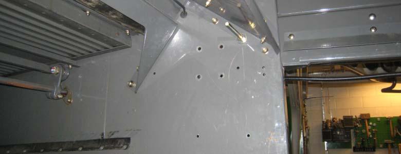
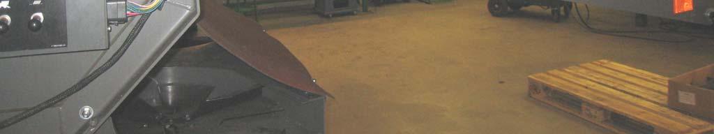
3 Removal of Belt shields and Brackets Remove Bracket Remove Bracket Remove Bracket Remove Belt shield Remove Bracket Remove Bracket Remove Belt shield 3


4 Removal of Belts and Pulley Remove Harness shield Remove Pulley and hub Remove Belt 4


5 Removal of Ladder and Railings Remove Ladder Remove Railing Remove Railing Remove Ladder Bracket 5


6 Removal of Tailboard, Chopper and Actuators Remove Actuator Remove Actuator Remove Tailboard Remove Chopper 6


7 Removal of Rear light arms and Bracket for license plate Remove Light arm Remove Bracket for license plate Remove Light arm 7


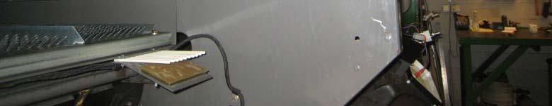
8 Removal of Hood and Actuator brackets Remove Actuator bracket Remove Hood Remove Actuator bracket 8


9 Installation of Hood and Brackets Bracket Carriage bolt M8x25, washer and nuts Top Side sheet Front roof plate Bottom Side sheet Rear roof plate Light arm bracket M8x30, washer, nut Bottom Side sheet Bottom Side sheet Cross plate M8x20, washers and nuts Rubber Pop rivet Ø4,8x14 9


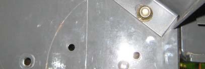
10 Installation of Chopper and Locking list Removal of Pulley and Hub Replace with new Locking list Screw M8x25 Washers and nut Current Pulley and Hub shall be removed Chopper 10
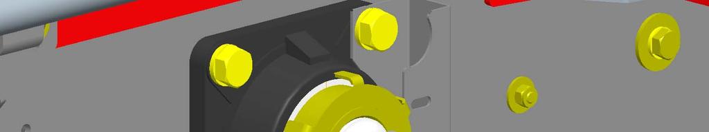


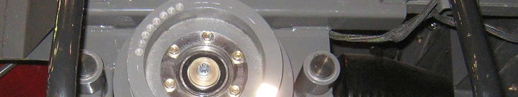
11 Installation of Claw clutch 1. Key 3/8 x3/8 2. Pulley with hub 4. Tighten set screw 3. Washer 10,5x50x8 Screw M10x30 Lock washer 11


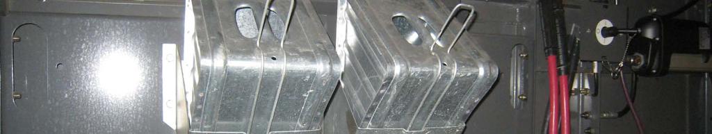
12 Installation of Claw clutch 5. Springs and balls 5. Springs and balls 6. Claw disc 8. Grease 7. Circlip 8. Grease Place holes in Pulley and Claw disc, concentric when engaging claw clutch 12
 Combine")
")
 Not included in the")


13 Installation of Idler bracket 1(3) Combine original pulley (Picture show high speed pulley) Idlers, p/n (2x) Not included in the kit and must be ordered separately M10x35, washers and nuts Drill holes Ø11 M10x40, washers and nuts See next page for using of shims Stay, nuts and washers 13


14 Installation of Idler bracket 2(3) Adjust vertical position with Shim t=1 and/or Shim t=3 Jack shaft pulley Chopper pulley Jack shaft pulley 1,5 mm 1,5 mm Chopper pulley 14


15 Installation of Idler bracket 3(3) Adjust belt alignment with stay Rear Jack shaft pulley Front jack shaft pulley Rear jack shaft pulley Front jack shaft pulley 1,5 mm 2 mm 15


16 Installation of Rails and Stair Use existing hardware Rail top Rail front Rail rear Stair Use existing hardware Reuse clamps M8x25, washers and nuts M8x25, washers and nuts 16


17 Installation of Rear Slide list Slide list, M8x25, washers and nuts 17


18 Installation of Harness shields Rear harness shield Use existing hardware Front harness shield Use existing hardware 18


19 Installation of Actuator and Brackets LH Use existing hole and hardware. Screw M12x55 Nuts Actuator Actuator support and Clamp Screw M8x25 Washers and Nuts Rear lh Actuator bracket Front lh Actuator bracket Screw M8x25 Washers and nuts Screw M12x80 Nuts 19


20 Installation of Actuator and Brackets RH Front rh Actuator bracket Actuator Screw M12x55 Nuts Front RH Actuator bracket Screw M10x25, M10x30 Washers and Nuts Rear rh Actuator bracket Drill one new hole Ø11 Use existing screws and M10x25, Washers And Nut Screw M12x55 Nuts 20


21 Installation of Brackets for Shields Bracket M10x25, washers and nut Bracket Use existing hardware Bracket M8x25, washers and nut and existing hardware 21


22 Installation of Electric box and Actuator support Actuator support and Clamp Screw M8x25 Washers and Nuts Electric box Screw M8x25 Washers and Nuts 22


23 Installation of Chopper shield Chopper shield Existing hole M8x20, washers and nut Existing hole M8x20, washers and nut Drill hole Ø9 M8x20, washers and nut Drill hole Ø9 M8x20, washers and nut Drill hole Ø9 M8x20, washers and nut 23
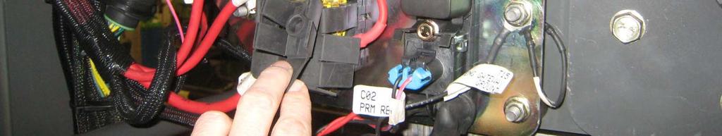
24 Overview of electric harness Connect to Electric clutch Connect to +12 VDC Connect to Idler speed alarm Connect to Actuator RH Connect to Actuator LH Connect to Combine original connector for speed. Connect to Chopper speed alarm Connect to Chassis ground Connect to Clutch sensor Connect to Electric box 24


25 Harness connection to Electric clutch 25


26 Harness connection to Power supply +12 VDC 26


27 Harness connection to Actuator LH Connect to Actuator LH 27


28 Installation of Idler speed sensor Harness connection to Idler speed sensor Connect to Idler speed alarm Install Idler speed sensor Adjust to 2±1 mm between sensor and gear tooth. 28


29 Harness connection to Combine original connector for speed If combine is equiped with a 3-way connector shall it be replaced with a Deutsch DT06-4S, sockets, wedge lock and plug. These parts are included in the kit. Wiring i diagram 4-White-Signal 1-Red-Supply 2-Black-Ground Connect to Combine original connector for speed. 29


30 Installation of Chopper sensor Harness connection to Chopper speed sensor Install Chopper speed sensor Adjust to 2±1 mm between sensor and gear tooth. Clamp Clamp Clamp Connect to Chopper speed alarm 30


31 Installation of Clutch sensor Harness connection to Clutch sensor Install Clutch sensor Adjust to 4±1 mm between sensor and disc when disc is fully out. Clamp Connect to Clutch sensor 31


32 Harness connection to Actuator RH Connect to Actuator RH 32


33 Harness connection to Electric box Connection to Chassis ground Clamp 1. Drill hole Ø9. 2. Remove paint for good ground connection. 3. Connect eyelet to chassis ground. Connect to Electric box 33


34 Installation of Belts 1. Install tertiary ti belt See following pages for adjusting belt tension. 2. Install secondary belt See following pages for adjusting belt tension. 34


35 Installation of Belts Adjustment of belt tension on tertiary belt when straw chopper is in chopping position. 1. Make sure chopper is in fully forward position (chopping position) If chopper is somewhere between forward and backward position when tighten belt will the belt be over tighten and failure. 2. Tighten nut until washer aligns with the gauge. Do not over tighten. 35


 If")


36 Installation of Belts Adjustment of belt tension on tertiary belt when straw chopper is in windrowing position. 1. Make sure chopper is in fully rearward position (windrowing position) If chopper is somewhere between forward and backward position when tighten belt will the belt be over tighten and failure. 2. Tighten nut until washer aligns with the gauge. Do not over tighten. 36

 until the spring")
. If there is a gap of more then 2")

37 Installation of Belts Adjustment of belt tension on secondary belt With the belt installed, tighten the adjustment nuts (2) until the spring guide (3) contacts the spring housing (4). If there is a gap of more then 2 mm between the spring guide and the spring housing, then adjustment is needed. 37


38 Installation of Shield 3. Shield Tigthen ¼ turn latch Shield M8x20 Washers and nuts Shield M8x20 Washers and nuts 38


39 Installation of Shields 4. Slide list M8x20, M8x25, washer and nuts 5. Shield M8x20, M8x25 Washers and nuts 39


40 Installation of Light arms and bracket for license plate Bracket for license plate New position of light arm Original position of light arm 40


41 Add hole for new position This hole can maybe already exist. If not shall hole be added. Existing hole Drill new hole Ø13 41


42 Installation of Chaff Curtain Drill new holes Ø13 Install Pins, Pin, washers and lock nuts Adapter plate Pop rivets Ø4,8x10 Curtain Ball screws, washers and nuts 42


43 Installation of Straw forks Straw forks in windrowing position Straw forks in parking position 43


44 Installation of Hooks on ladder Replace with new hooks Use existing hardware 44
45 Test run Before Test run Check that Electric harness do not interfere with belt and pulleys. Test run Move chopper to chopping position (front position) Engage claw clutch. Run separator at high idle. Check for abnormal vibrations. After Test run Leave user s manual and spare part list in the cabin. 45
SPARE PART LIST. Maxi Spreader for MF 9895 p/n 13692
 SPARE PART LIST 2014-05-07 Maxi Spreader for MF 9895 p/n 13692 Rekordverken Sweden AB Öttum 535 92 KVÄNUM Tel. +46-511-303 00 Fax. +46-511-303 01 1 T0876 Maxi Spreader 2 Key Qty Description Dimension Rekord
Installation of Chaff Deck for Case 30/40 Series
 Installation of Chaff Deck for Case 30/40 Series Please be aware that the following steps require moving heavy components. Lift with knees bent and back straight! Pre-Installation Steps Move spreader
Printed from CyberCat-STIGA Section: GARDEN ELECTRICAL SYSTEM
 Section: GARDEN ELECTRICAL SYSTEM Section: GARDEN ELECTRICAL SYSTEM 2312 2333 1 1 1134-3625-01 Harness 2 1 1134-3623-02.Interlock module 4 2 9849-8013-16 Screw 5 2 1134-3132-01 Cable holder 6 2 1134-3204-01
Illustrated Parts & Packing List & Instructions 815 Rice Lake Street, Owatonna, MN 55060
 Illustrated Parts & Packing List & Instructions 815 Rice Lake Street, Owatonna, MN 55060 Great Plains Part #891-622C (Gandy Part #6245DS-TT) Great Plains Turbo-Till & Turbo-Chopper 2400/3000 Models 45
MC2 BOWLING Pin-Setter
 MC2 BOWLING Pin-Setter File No.: M200509-01 COPYRIGHT 2005, VIA BOWLING PRODUCTS Content I. Installation of Front-End Assembly --------------------------------------- 1 II. Installation of Back-End Assembly
Part s Catalog. LX500 Lawn Tractor. Model No. 13AP60RP744. Original Instructions (EN) (01/31/06)
 (01/31/06)") Part s Catalog For Parts Call 0-- or 0-- LX00 Lawn Tractor Model No. AP0RP Original Instructions (EN) -0 (0//0) For Parts Call 0-- or 0-- Model P0RP NUMBER --00 Turf Tire, 0 x 0.0 x -000-00 Rim,.0 x.0-0-0
Part s Catalog For Parts Call 0-- or 0-- LX00 Lawn Tractor Model No. AP0RP Original Instructions (EN) -0 (0//0) For Parts Call 0-- or 0-- Model P0RP NUMBER --00 Turf Tire, 0 x 0.0 x -000-00 Rim,.0 x.0-0-0
Spare parts list Trowel STG244 F TP
 Spare parts list Trowel STG244 F TP Valid from serial number Valid to serial number BGF111601- www.cp.com STG244 F TP Spare parts list General information This spare parts list applies to the following:
Overview SC 800 / 800 propane
 Table 0-1 Spare parts grinding head Overview SC 800 / 800 propane Figure 0-1 Overview of SC-800 Item Reference / art no. Description 1 570627 Handle 2 570039 Sprint to adjust handle 3 911008 Water connection
Supplement to Spare Parts Catalogue. Model : FT Dual Transmission - F
 Supplement to Spare Parts Catalogue Model : FT - 60 Dual Transmission - F10001760 CONTENTS Tab. No. Sheet No. DESCRIPTION Page No. 1 101764-8 HEAD LIGHT, REAR LIGHT AND PLOUGH 1 LAMP 2 101766A-7 SHEET
1 RS-300/D 320/D 340/D 350H Parts Manual
 300/D 320/D 340/D 350H Parts Manual Table Of Contents Three Point Hitch / Hitch Frame Assembly... 3 Tongue Pull Hitch Assembly... 7 Main Gearbox... 11 Crank Handle & Gear... 13 Hydraulic Lift... 15 Rotor
Part s Catalog. GT2100 Garden Tractor. Model No. 14AP80RP744. Original Instructions (EN) (01/31/06)
 (01/31/06)") Part s Catalog GT0 Garden Tractor Model No. AP0RP Original Instructions (EN) -0 (0//0) Model P0RP -0-00 Turf Tire, x. x -0-00 Rim,.0 x.0-00 Lug Nut, /- -00A-0 Wheel Assembly, x. x -00-00 Rim Assembly,.0
Part s Catalog GT0 Garden Tractor Model No. AP0RP Original Instructions (EN) -0 (0//0) Model P0RP -0-00 Turf Tire, x. x -0-00 Rim,.0 x.0-00 Lug Nut, /- -00A-0 Wheel Assembly, x. x -00-00 Rim Assembly,.0
SPARE PARTS BOOK Ride-on mower with front-mounted, mulching cutter deck GTM 1350DL
 SPARE PARTS BOOK Ride-on mower with front-mounted, mulching cutter deck GTM 1350DL 1 GTM1350 REMARKS ON THIS SPARE PARTS CATALOGUE * This spare part catalogue contains all spare parts for the GTM1350
Automatic Lawn Tractor Model Series 600
 Illustrated Parts Manual Automatic Lawn Tractor Model Series 600 MTD LLC, P.O. BOX 6 CLEVELAND, OHIO 6-009 Printed In USA Form No. 69-09 (January 8, 008) -Style Fender, Deck Lift & Seat 6 6 0 8 On some
Models E640F, E660F, E6C0F & E660G
 Models E0F, E0F, EC0F & E0G 0 0 0 0 0-0 Lock Jam Nut /- -0 Flat Idler -B Auger Idler Arm 0-0A Hex Cap Screw /- x.0-0 Shoulder Screw -0 Flat Washer,. x. x.0-0 Extension Spring -0 Hex Nut /- -00 Hex Nut
Part s Catalog. LX420 & LX460 Lawn Tractors. Model No. 13AX60RG744 Model No. 13AX60RH744
 Part s Catalog For Parts Call 0-- or 0-- LX0 & LX0 Lawn Tractors Model No. AX0RG Model No. AX0RH Original Instructions (EN) -0 (0//0) Models X0RG & X0RH --00 Turf Tire, 0 x.0 x -000-00 Rim,.0 x.0-0-0 Wheel
Models 642E, 642F, 662E, 644E, 664F, & 6A4E
 Models E, F, E, E, F, & AE 0 0 0 0 Models E, F, E, E, F, & AE. -0 Lock Jam Nut /-. -0 Flat Idler. -B Auger Idler Arm. 0-0A Hex Cap Screw /- x.0. -0 Bushing. -0 Bell Washer. -00 Hex Nut /-. -0 Hex Lock
New Holland TR MAV Complete Chopper Installation Guide
 TM New Holland TR MAV - 100 Complete Chopper Installation Guide CH003-01_SEP_2014 ROTOR BLADE A IMPORTANT! The paddle blades, located on the balance rings inside the chopper, must be installed in the direction
Illustrated Parts & Packing List & Instructions 815 Rice Lake Street, Owatonna, MN 55060
 Illustrated Parts & Packing List & Instructions 815 Rice Lake Street, Owatonna, MN 55060 Great Plains Part #891-561C (Gandy Part #6245DS-GP) For Great Plains Turbo-Max 2400, 3000, 3500 & 4000 Models 45
Printed from CyberCat-STIGA Section: ESTATE PRESIDENT ESTATE TORNADO HST BRAKE CONTROL DRIVE CONTROL
 Section: ESTATE PRESIDENT ESTATE TORNADO HST BRAKE CONTROL DRIVE CONTROL Section: ESTATE PRESIDENT ESTATE TORNADO HST BRAKE CONTROL DRIVE CON 2522 2532 1 1 1136-0510-01 Pedal 2 1 1136-0151-01 Pedal cover
CANVAS DOOR KIT P/N , APPLICATION BEFORE YOU BEGIN KIT CONTENTS. Verify accessory fitment at Polaris.com.
 CANVAS DOOR KIT P/N 2882902, 2882903 APPLICATION Verify accessory fitment at Polaris.com. BEFORE YOU BEGIN Read these instructions and check to be sure all parts and tools are accounted for. Please retain
Spare Parts B WR
 7 CRT 52 1.1997 Spare Parts 954 14 00-20B WR 01-07-98 HANDLE ASSEMBLY 1 871191008 Screw, Phd. #10-24 UNC 2 532126956 Panel, Control 3 532104164 Tie, Cable 4 532124797 Grip, Handle 5 532124788 Clip, Hairpin
62 Deck Idler Kit High Speed
 Part No. 00 FORM NO. -899 6 Deck Idler Kit High Speed For Model 70 Serial No. 99000 to 99000 For Model 7 Serial No. 9900 to 99000 INSTALLATION INSTRUCTIONS Loose Parts Note: Use the chart below to identify
Transmatic Lawn Tractor Model Series 700
 Illustrated Parts Manual Transmatic Lawn Tractor Model Series 00 MTD LLC, P.O. BOX CLEVELAND, OHIO -00 Printed In USA Form -0 (February, 00) Model Series 0 0 0 Model Series Part 0-0 Self-Tapping Screw
RIDE ON MOWERS Model # Mini Rider. Issue A.0 ECN Sept 2014 PB Ref #
 RIDE ON MOWERS Model # Mini Rider ECN 11649 Contents Frame & Fender............... Page 3 Drive System................. Page 4 Seat & Electrical......... Page 5 Front End Steering.............. Page 6
Autodrive Lawn Tractor
 Illustrated Parts Manual Autodrive Lawn Tractor MTD LLC, P.O. BOX CLEVELAND, OHIO -009 Printed In USA Form No. 9-00 (September, 2009) Steering & Front Axle Assembly 2 9 0 2 9 2 20 9 2 20 2 22 2 2 2 2 2
Automatic Lawn Tractor Model Series 600
 Illustrated Parts Manual utomatic Lawn Tractor Model Series 00 MTD LLC, P.O. BOX 11 CLEVELND, OHIO -00 Printed In US Form No. -08 (February 18, 008) Fender, Deck Lift & Seat 5 5 Models w/ Manually djusting
REPAIR PARTS SNOW THROWER - - MODEL NO. PR827ES ( ) AUGER HOUSING / IMPELLER ASSEMBLY
 AUGER HOUSING / IMPELLER ASSEMBLY") REPAIR PARTS SNOW THROWER - - MODEL NO. PR8ES (00000) AUGER HOUSING / IMPELLER ASSEMBLY (x) (x) 0.0.00-A 0X8 AUGER HOUSING 0X SCRAPER BAR 00 CARRIAGE BOLT / 8 X. NUT / 8 0.0.0-B 08 AUGER BEARING BEARING
REPAIR PARTS SNOW THROWER - - MODEL NO. PR8ES (00000) AUGER HOUSING / IMPELLER ASSEMBLY (x) (x) 0.0.00-A 0X8 AUGER HOUSING 0X SCRAPER BAR 00 CARRIAGE BOLT / 8 X. NUT / 8 0.0.0-B 08 AUGER BEARING BEARING
ILLUSTRATED PARTS MANUAL
 ILLUSTRATED PARTS MANUAL Transmatic Lawn Tractor Models 760-779 IMPORTANT READ SAFETY RULES AND INSTRUCTIONS CAREFULLY BEFORE OPERATION Warning: This unit is equipped with an internal combustion engine
OPERATOR S MANUAL MAINTENANCE MANUAL PARTS LIST TURFCO METE-R-MATIC III. Top Dresser. Model F12D. Product Number 85423
 Model FD OPERATOR S MANUAL MAINTENANCE MANUAL PARTS LIST TURFCO Top Dresser Model FD Product Number U.S. Patents,,;,0,;,0, Other Patents Pending Manual Number Rev B DANGER - IF INCORRECTLY USED THIS MACHINE
TECHNICAL DATA BROCHURE ZTR 308/3II
 Date 8/84 Page 1 of 6 TECHNICAL DATA BROCHURE ZTR 308/3II IMPORTANT - READ OPERATOR'S MANUAL BEFORE OPERATION OR MAKING ADJUSTMENTS. ' Seat Adjustment Loosen bolts on sliding brackets under each side of
A 1 SERVICE SPECIFICATIONS
 A1 A2 Clutch CLUTCH Specifications Pedal height (from asphalt sheet) Release point (from pedal stroke end position) Push rod play at pedal top Pedal freeplay Disc rivet head depth Disc runout Diaphragm
400 2x4/4x4 EFT SHARE OUR PASSION ṬM
 SHARE OUR PASSION ṬM 400 2x4/4x4 EFT Model Number A2009IDG2BETR (Red - 2x4) Model Number A2009IDG2BETZ (Cat Green - 2x4) Model Number A2009IDG4BETR (Red - 4x4) Model Number A2009IDG4BETG (Green - 4x4)
Illustrated Parts Manual
 Illustrated Parts Manual Transmatic Lawn Tractor MODELS 70, 770 7, 77 7, 77 7, 77 MTD LLC, P.O. BOX CLEVELAND, OHIO -7 PRINTED IN U.S.A. FORM 7-0 (//00) Models 70 & 770 A 7 0 8 0 8 7 8 A 0 Models 70 &
PWC - 33
 PWC - 33 WY33N13BS SPARE PARTS LIST Mower Assembly Caster Kit Ref.# Part# Description Ref.# Part# Description 1 3301010 Linchpin 11 B6182-12 Lock nut M12 2 B97.1-20 Washer 20 12 3301040 Caster Wheel Arm
Twin Master Combine. Transmission & Gear Boxes Section 8. 2 Speed Transmission Transmission Gear Shift
 Twin Master Combine Transmission & Gear Boxes Section 2 Speed Transmission... 2-4 Transmission Gear Shift... 5-6 PTO Swivel Gear Box 107021... 7- Transition Auger Gear Box 107026... 9-10 Straw Chopper
4g.1 - Flatbed Feeder Main Assembly A4440A
 PAGE NO. 1 OTHER ASSEMBLIES NOT SHOWN ON THIS DRAWING: A7029A - LONG CONVEYOR ASSEMBLY - SECTION 4g.2 A7101A - SEPARATOR (FB) ASSEMBLY - SECTION 4g.8 A7103A - CHASSIS ASSEMBLY - SECTION 4g.9 A7107A - TOP
SPARE PARTS LIST RIDERS P525 D, , 2016
 SPARE PARTS LIST RIDERS P525 D, 967602101, 2016 CABIN P525 D, 967602101, 2016 CABIN P525 D, 967602101, 2016 Ref Part No Description Remark QTY KIT 1 501 99 86-01 DOOR 1 2 501 99 87-01 SEAL 1 3 579 86 79-01
PARTS LISTING a WR
 7 CRT 3 2.1 PARTS LISTING 54140066a WR 02-1- HANDLE ASSEMBLY 1 711100 Screw, Pan Hd. #10-24 UNC 2 53212656 Panel, Control 3 532104164 Tie, Cable 4 53212477 Grip, Handle 5 5321247 Clip, Hairpin 6 5320132
The parking brake is an electrically actuated system that operates drum brakes integrated into the rear brake discs. The
 Page 1 of 15 Published: Oct 22, 2004 Parking Brake COMPONENT LOCATIONS Item Part Number Description 1 Clutch pedal position sensor (manual transmission models only) 2 Parking brake indicators (all except
OVERHAUL. NOTICE: Do not apply grease to each sliding part of the link. HINT: COMPONENTS: See page REMOVE REAR FLOOR FINISH PLATE
 7528 ENGINE HOOD/DOOR OVERHAUL NOTICE: Do not apply grease to each sliding part of the link. COMPONENTS: See page 7526 7506701 1. REMOVE REAR FLOOR FINISH PLATE Using a screwdriver, remove the rear floor
REPAIR PARTS SNOW THROWER - MODEL NUMBER AUGER HOUSING / IMPELLER ASSEMBLY
 REPAIR PARTS SNOW THROWER - MODEL NUMBER 0000 AUGER HOUSING / IMPELLER ASSEMBLY 3 7 8 7 3 37 7 38 7 0 3 3 7 8 33 8 3 3 3 0 3 8 3 8 0 7 7 30 8 0 7 38 REPAIR PARTS SNOW THROWER - MODEL NUMBER 0000 AUGER
MODEL NUMBER 12527HV PRODUCT NUMBER MFG. ID. NUMBER
 ILLUSTRATED S LIST MODEL NUMBER HV PRODUCT NUMBER 00- MFG. ID. NUMBER 000 0 - Rev REPAIR S AUGER HOUSING / IMPELLER ASSEMBLY SNOW THROWER - MODEL HV (000), PRODUCT 00-0 0 0 (EXPLODED) 0.0.0-F NOTE: All
I Illustrated Parts List CRT B. Tiller. Repair Parts Manual
 Illustrated Parts List 15-12 I502012 CRT 1 54001152B Repair Parts Manual Tiller HANDLE ASSEMBLY 1 711100 Screw, Pan Hd. #10-24 UNC 2 53212656 Panel, Control 3 532104164 Tie, Cable 4 53212477 Grip, Handle
Model Series E6A5E, E645E & E665E
 Model Series EAE, EE & EE 0. -0 Housing R.H. -0 Housing L.H.. 0-0 Hex Screw /- x.. -0A Spiral Axle -00A Spiral Axle. -0 Key. -0 Pin-Spiral. -0 Shaft-Worm. -0 Gear-Worm. -0 Collar-Thrust. -0 Plug 0. -0
SEAT LCR TCR V3 SEQ Tightening Torque Manual
 SEAT LCR TCR V3 SEQ Tightening Torque Manual INDEX Notes Engine Fly Wheel And Clutch Engine & Gearbox Supports Turbocharger Alternator Fuel System Intermediate Axle Drive Shaft Gear Shift Actuator Front
IPL, ST276 EP, , ST276 EP
 IPL, ST EP, 00, 0- ST EP Spare parts Ersatzteile Pièces détachées Reserve onderdelen Repuestos Reservdelar AUGER HOUSING / IMPELLER ASSEMBLY 0 0 (EXPLODED) 0.0.0-D NOTE: All component dimensions given
LIFTKET wire rope winch with wall bracket or foot support
 Issue August 2014 Spare part list LIFTKET wire rope winch LSF 175/1-19 LSF 200/1-15 LIFTKET wire rope winch with wall bracket or foot support SP-Code Description Description of spare part section Page
MODEL NUMBER 1830HV PRODUCT NUMBER MFG. ID. NUMBER
 ILLUSTRATED S LIST MODEL NUMBER 0HV PRODUCT NUMBER 00- MFG. ID. NUMBER 000 0 0-0 AUGER HOUSING / IMPELLER ASSEMBLY SNOW THROWER - MODEL 0HV (000), PRODUCT 00-0 0 0 (EXPLODED) 0.0.0-F NOTE: All component
ILLUSTRATED PARTS LIST MODEL NUMBER 15530SB-LS PRODUCT NUMBER MFG. ID. NUMBER TH
 ILLUSTRATED PARTS LIST MODEL NUMBER SB-LS PRODUCT NUMBER 00- MFG. ID. NUMBER 000-0.0.0 TH AUGER HOUSING / IMPELLER ASSEMBLY 0 0 (EXPLODED) 0.0.0-C NOTE: All component dimensions given in U.S. inches. inch
ATV I l. l u. r a. Parts Manual ARCTIC CAT. 250 cc/300 cc
 2000 I l l u st ATV 250 cc/300 cc Model No. A2000ATE2AUSG (250 - Green) Model No. A2000ATE2AUSR (250 - Red) Model No. A2000ATF2AUSG (300 2x4 - Green) Model No. A2000ATF2AUSR (300 2x4 - Red) Model No. A2000ATF4AUSG
SECTION 12: ILLUSTRATED PARTS LIST
 SECTION : ILLUSTRTED S LIST (for choke) (for throttle) 0 0-0 Screw, #- x.0 0-0 Screw, /- x.0 0-0 Screw, /- x.0 0- Screw, #0- x. 0- Socket Cap Screw, /- x. 0- Self-tapping Screw, /- x. -00 Flange Lock Nut,
Printed from CyberCat-STIGA Section: VILLA ACCESSORY BAG
 Section: VILLA ACCESSORY BAG Section: VILLA ACCESSORY BAG Pos. Quantity Spare part No Description Kit Notes New 2721 2722 2723 2724 0 1 1134-4664-01 Accessory bag assy 1 1 9595-0262-00.Locating pin 2A
9895 Combine Parts Catalog EFF. S/N HSC8101
 9895 Combine Parts Catalog EFF. S/N HSC8101 1 FORWARD ALPHABETICAL INDEX The complete alphabetical index appears at the beginning of this publication. It is used to locate major groups, assemblies and
ILLUSTRATED PARTS LIST MODEL NUMBER 14527E PRODUCT NUMBER MFG. ID. NUMBER
 ILLUSTRATED S LIST MODEL NUMBER E PRODUCT NUMBER 00- MFG. ID. NUMBER 000 0 0 - AUGER HOUSING / IMPELLER ASSEMBLY SNOW THROWER - MODEL E (000), PRODUCT 00-0 0 0 (EXPLODED) 0.0.0-F NOTE: All component dimensions
BEFCO. Parts Manual CYCLONE FLEX. Gang Grooming Mower 312-FLX, 315-FLX & 317-FLX. Manual B October 2008
 BEFCO Parts Manual CYCLONE FLEX Gang Grooming Mower -FLX, 5-FLX & 7-FLX Manual 90-07B October 00 BEFCO PM, 5, 7-FLX (US) Printed on October, 00 Parts Manual /007 FLX-, 5, 7 Ver. L FLEX, 5 & 7 MAIN FRAME
126in Quadfloat Mower Groundsmaster 455 D
 Form No. 3326-597 126in Quadfloat Mower Groundsmaster 455 D Model No. 30402 210000001 and Up Parts Catalog Ordering Replacement Parts To order replacement parts, please supply: the part number, the quantity,
CYLINDER HEAD - CYLINDER
 A1 CYLINDER HEAD - CYLINDER 1 8AY-11111-00-00 HEAD, CYLINDER 1......... 1 2 8A7-12499-00-00 JOINT................... 1 3 NGK-BR9ES-00-00 PLUG, SPARK............. 2 4 8AY-11181-00-00 GASKET, CYLINDER HEAD
POWER RAKE PARTS CATALOG MODEL 1305PR SERIAL NUMBER AND ABOVE
 POWER RAKE PARTS CATALOG MODEL 0PR SERIAL NUMBER 000 AND ABOVE Turf Teq LLC PC0PR--0--0 Contents Part Number Page Number 0--0... Sector A... 0--0... Engine A... 0--0... Hydro Handle A... 0--0... K Transmission
MODEL NUMBER 11524E PRODUCT NUMBER MFG. ID. NUMBER
 ILLUSTRATED PARTS LIST MODEL NUMBER E PRODUCT NUMBER 000 MFG. ID. NUMBER 00-0 0 - AUGER HOUSING / IMPELLER ASSEMBLY SNOW THROWER - MODEL NO. E (000), PRODUCT NO. 00-0 0 0 (EXPLODED) 0.0.0-F AUGER HOUSING
Mounting plates with predrilled holes for mounting angles Mounting kits Slider... Slider SK-V 20...
 Table of contents Product catalogue 2005... 1 Georg Fischer Transportation Engineering... 4 Fifth wheels... 5 Fifth wheels... 6 20t imposed load... 7 SK-S 36.20 PLUS (standard)... 7 Spare parts SK-S 36.20
MODEL NUMBER 14527SB-LS PRODUCT NUMBER MFG. ID. NUMBER
 ILLUSTRATED S LIST MODEL NUMBER SB-LS PRODUCT NUMBER 9 9 00-9 MFG. ID. NUMBER 9900900 009-0 -90 Rev. 0.09.09 SR AUGER HOUSING / IMPELLER ASSEMBLY SNOW THROWER - MODEL SB-LS (9900900), PRODUCT 9 9 00-9
SPARE PARTS MANUAL FOR LOG SPLITTER
 ENGLISH Hakki Pilke 37 SPARE PARTS MANUAL FOR LOG SPLITTER MAASELÄN KONE OY Valimotie 1, FI-85800 Haapajärvi, Finland Tel. +358 (0)8 7727300, Fax +358 (0)8 7727320 info@maaselankone.fi www.maaselankone.fi
Drum mower BDR-595E. EuroAdela. Spare part list
 Drum mower BDR-595E EuroAdela Spare part list 1. Covers 2 Covers Pos. Name Size Drawing-Standard Ord. No. Pcs 1 Frame 22 9 1536 050 196 001 1 2 Screen frame front part 22 9 1856 008 196 018 1 3 Screen
MODEL NUMBER ST230E PRODUCT NUMBER MFG. ID. NUMBER
 ILLUSTRATED PARTS LIST MODEL NUMBER ST0E PRODUCT NUMBER 0000 MFG. ID. NUMBER 00-0 - AUGER HOUSING / IMPELLER ASSEMBLY SNOW THROWER - MODEL NO. ST0E (0000), PRODUCT NO. 00-0 0 0 (EXPLODED) 0.0.0-F NOTE:
TECHNICAL DATA BROCHURE ZTR 426
 TECHNICAL DATA BROCHURE ZTR 426 Date 8/84 IMPORTANT - READ OPERATOR'S MANUAL BEFORE OPERATION. Page 1 of 6 Seat Adjustment Loosen bolts on sliding bracket under each side of seat, slide seat forward or
13AU609H063 (1999) Page 1 of 25 Axle & Wheels Front And Steering Assembly
 Page 1 of 25 Axle & Wheels Front And Steering Assembly") 13AU609H063 (1999) Page 1 of 25 Axle & Wheels Front And Steering Assembly 13AU609H063 (1999) Page 2 of 25 Axle & Wheels Front And Steering Assembly 1 683-0304 1 S Frame 2 710-0604A 1 /P Self-tapping Screw,
13AU609H063 (1999) Page 1 of 25 Axle & Wheels Front And Steering Assembly 13AU609H063 (1999) Page 2 of 25 Axle & Wheels Front And Steering Assembly 1 683-0304 1 S Frame 2 710-0604A 1 /P Self-tapping Screw,
INSTALLATION INSTRUCTIONS 8" CONTINUOUS FLOW/TRANSFER AUGER QUICK RELEASE POWERHEAD 702B-001A AND 702E-001A
 INSTALLATION INSTRUCTIONS 8" CONTINUOUS FLOW/TRANSFER AUGER QUICK RELEASE POWERHEAD 702B-001A AND 702E-001A SHIVVERS MANUFACTURING, INC. 614 W. ENGLISH STREET CORYDON, IA 50060 PH (641) 872-1005 **FAX
P/N: , Rev-E, 14/07/2016 Modified on 07/ V/60Hz
 P/N: 557360023-00, Rev-E, 14/07/2016 Modified on 07/16 1 110V/60Hz 2 21 22 53 35 19 12 52 31 15 51 45 18 60 57 5 46 26 11 48 7 66 36 14 28 29 30 65 41 46 58 47 40 37 33 32 8 23 3 SL.NO PART NO DESCRIPTION
PR624ES OWNER'S MANUAL MODEL NUMBER: SNOW THROWER
 IMPORTANT MANUAL Do Not Throw Away OWNER'S MANUAL MODEL NUMBER: PRES SNOW THROWER WARNING: Read the Owner's Manual and fol low all Warnings and Safety In struc tions. Fail ure to do so can result in serious
Installation Manual. LHS & LLBS Hide-A-Way Tuckunder Style
 Installation Manual LHS & LLBS Hide-A-Way Tuckunder Style 10900 Kenwood Road Cincinnati, OH 45242 Ph: 513-891-6210 Toll-Free: 866-539-6261 Fax: 513-891-4901 www.leymanlift.com sales@leymanlift.com LML00136-5/1/15
Illustrated Parts List / / 924 SB
 9SB Illustrated Parts List / 990000 / 9 SB AUGER HOUSING / IMPELLER ASSEMBLY SNOW THROWER - MODEL 9SBb (990000), PRODUCT 9 9 00-0 9 0 9 0 (EXPLODED) 9 0.0.00-B NOTE: All component dimensions given in U.S.
Parts Catalog HTC 1500iXT v.1
 Parts Catalog HTC 1500iXT www.htc-floorsystems.com/support 2017 v.1 Grinding head connection 12 13 17 18 14 16 15 19 20 21 Item Description Part no Qty 1 SCREW M6x16 310292 5 2 FOOT PLATE 500354 1 3 VIBRATION
Serial Number Range Electric Start & Bumper
 850 Electric Start & Bumper Serial Number Range 1000-6663 01.00 1 300.00276 KEY 2 300.00277 SWITCH 3 311.11090 SCREW M6X10 4 311.12158 SCREW M8X70 VANGARD ENGINE 5 312.11060 NUT M6 6 312.41060 NUT, SELF
Quadfloat 126 For Groundsmaster 455D
 Form No. 3324 134 Quadfloat 126 For Groundsmaster 455D Model No. 30402 200000201 and Up Parts Catalog Ordering Replacement Parts To order replacement parts, please supply: the part number, the quantity,
EUROPEAN REAR ENGINE RIDER SERIES 20
 Parts Manual for EUROPEAN REAR ENGINE RIDER SERIES 20 MODEL E281320BE E331520KVE McDonough, GA, 30253 U.S.A. Briggs & Startton Yard Power Products Group Copyright 2006 Briggs & Startton Corporation Milwaukee,
SPARE PARTS CATALOGUE
 SPARE PARTS CATALOGUE Liberty 50 2T Historical catalogs 1998-2005 345 Index Finished products... 4 Alphanumeric index... 5 Electrical equipment... 10 Table T36 - Electrical devices... 10 Table T37 - Optical
2010+ Victory Cross Country / Cross Roads Installation Guide Nov 2014
 2010+ Victory Cross Country / Cross Roads Installation Guide Nov 2014 125 Industrial Drive Spearfish, SD 57783 Toll Free 888.3WHEELS w w w. l e h m a n t r i k e s. c o m UNDERSTANDING SAFETY LABELS &
Engineering Standards
 Installation The display mounts in a 2.84 by 1.51 cutout. Overall area necessary for installation is 3.2 by 2.5. Two 0.201d holes are provided for mounting screws. 2.840" 1.510.277.470 1.900 Ø 0.201" (2)
18SP680Rev3 EPA04 MBE 4000 Car Hauler Low Pressure Fuel Lines
 8SP680Rev3 EPA04 MBE 4000 Car Hauler Low Pressure Fuel Lines KIT DESCRIPTION These service kits include all necessary parts to replace the low pressure fuel lines between the fuel filter housing and fuel
Installation Manual: Honda CRV Power Lift Gate System
 Installation Manual: Honda CRV Power Lift Gate System Page 1 of 18 NOTE: Installation Precaution 1. It is recommended to have this product installed by a professional to avoid damage caused by improper
Item No. Part Number Description Qty
 36 Frame Assembly 1 336-001 Hood 36" 1 2 100-009 Saucer Nut 4 3 300-001 Rear Deck Weldment 1 4 200-006 Nylon Nut M10 GB889-86 9 5 200-003 Hexagon Bolt M10*25 GB5783-86 12 6 100-007 Chute Deflector 1 7
CRT 51. Spare parts Ersatzteile Pièces détachées Reserve onderdelen Repuestos Reservdelar I SERVICE
 SERVICE 8 I9900001 IPL, CRT 51, 1999-02, 106 23 87-67 CRT 51 Spare parts Ersatzteile Pièces détachées Reserve onderdelen Repuestos Reservdelar Replaces Ersetzt Remplace Vervangt Reemplaza Ersätter 106
Section B Detector September B
 Section B Detector September 200 B Index No. Part No. Description. 2-0030-000 Link 2. 2-0208-000 Deck Hook Selector Assembly 3. 2-003-000 Spacer. -3000-000 Ball Bearing. 2-00-02 X-Washer Pin. 2-008-02
DPC6430. Documents DPC Tank and handle grips. 2 Hood, air filter. 3 Muffler, connecting muff. 4 Carburetor. 5 Starter assy., ignition assy.
 Documents 1 Tank and handle grips 2 Hood, air filter 3 Muffler, connecting muff 4 Carburetor 5 Starter assy., ignition assy. 6 Cylinder, crankshaft, clutch 7 Cutting device, protection hood 8 Blades, tools
HYDRO RIDER. DRWG No: R ISSUE No: Alternative Belt Retaining Bracket
 91 90 9 97 9 9 HYDRO RIDER 7 1 79 0 9 1 7 77 DRWG No: R0001 ISSUE No: 1 0 0 9 0 7 9 9 9 99 7 7 11 1 0 9 9 1 7 Alternative Belt Retaining Bracket 9 1 1 0 1 1 1 1 71 70 7 1 1 9 7 7 1 1 7 0 0 7 9 7 1 9 1
1 HR-301/D Parts Manual. Table Of Contents
 Table Of Contents 301/D Parts Manual 3 Point Hitch...2 Pull-Type Hitch...4 Main Frame...6 Angle Adjuster - Serial Number 44982 & Prior...8 Rotor Assembly - Serial Number 44982 & Prior...10 Rotor Assembly
TUFF TORQ TRANSAXLE. Tuff Torq Hydrostatic Transaxle. Transaxle Removal Tuff Torq
 Tuff Torq Hydrostatic Transaxle Internal Service 3. Disconnect the cotter pin and the washer to the brake rod (Figure 63). Internal service information is contained in the Tuff Torq KGIA Transaxle Service
Technical data. Part Thread (mm) Nm ±10% Tolerance Sidestand
 Nm ±10% Tolerance Sidestand") section 3 - Torque settings Frame torque settings Sidestand Stand sensor bolt 5 Pre-applied threadlocker Stand plate fixing screw M10x25 43 Pre-applied threadlocker Side stand fastening pin Side stand
section 3 - Torque settings Frame torque settings Sidestand Stand sensor bolt 5 Pre-applied threadlocker Stand plate fixing screw M10x25 43 Pre-applied threadlocker Side stand fastening pin Side stand
machines that have experienced premature failures. This applies to machines manufactured between January 2014 and March 2015.
 SERVICE BULLETIN 15-T2-30 DATE: 25.09.2015 REVISION No: 5 MODELS CONCERNED: MK4 B Series B60-4TRAC, B250-4TRAC, C50, C60, C80, F60-4TRAC, F250-4TRAC, T50, T60 & T80. CONCERN: The following procedure covers
X Dodge / Chrysler /2. Model 44 /216 Disconnect Front Axles for. W1500 and W2500 Ram
 Dodge / Chrysler 1994-1998 1 /2 Model 44 /216 Disconnect Front Axles for W1500 and W2500 Ram 15 Exploded View 16 Parts Listing ITEM NO. PART NUMBER DESCRIPTION 1 (3) Housing Axle Service 2 (1) Drive Pinion
REPAIR PARTS MANUAL MODEL NUMBER PM85 (MFG. ID. NO ) Snow Thrower BY Printed in U.S.A.
 Snow Thrower BY Printed in U.S.A.") MANUAL MODEL NUMBER PM8 (MFG. ID. NO. 990000) Snow Thrower 3 0 9-0.8.0 BY Printed in U.S.A. AUGER HOUSING / IMPELLER ASSEMBLY SNOW THROWER - MODEL NO. PM8 (990000), PRODUCT NO. 9 9 00-0 3 0 9 3 3 38 9
MANUAL MODEL NUMBER PM8 (MFG. ID. NO. 990000) Snow Thrower 3 0 9-0.8.0 BY Printed in U.S.A. AUGER HOUSING / IMPELLER ASSEMBLY SNOW THROWER - MODEL NO. PM8 (990000), PRODUCT NO. 9 9 00-0 3 0 9 3 3 38 9
Model Series 660 & 670
 Model Series 0 & 0 Part. -0A Harness Assembly. -0 Hex TT-Tap Scr. /-0 x. Lg.. -0 Hex Bolt /-0 x. Lg.. -00 Hex Bolt /- x. Lg.. -0 Speed Nut /-0 Thd.. -00A Flange L-Nut /- Thd.. -00 Hex Nut /-0 Thd.. -0
SPARE PARTS LIST HTC 650 RX
 GB SPARE PARTS LIST HTC 650 RX HTC 650 RX Table of contents Table of contents 1.... 2 1.1 Chassis... 2 1.2 Mist Cooler System... 6 1.3 Handle...10 1.4 Grinding head 1...12 1.5 Grinding head 2...14 1.6
MC Xpress AB Norra Altervägen ALTERSBRUK Sweden Tel:
 Installation manual power upgrade kit Yamaha Sidewinder / Arctic Cat ZR 9000 Stage 1 / 225 hp and stage 2 / 250 hp MC Xpress AB Norra Altervägen 821 945 92 ALTERSBRUK Sweden Tel: +46 911 202005 www.mcx.se
Parts Manual SERIES CVT Lawn Tractor. Model LT1040 CUB CADET LLC, P.O. BOX CLEVELAND, OHIO PRINTED IN U.S.A.
 Parts Manual CVT Lawn Tractor SERIES 000 Model LT00 PRINTED IN U.S.A. CUB CADET LLC, P.O. BOX CLEVELAND, OHIO -00 FORM -00C.fm (//00) SERIES 000 CVT LAWN TRACTORS TABLE OF CONTENTS DESCRIPTION PAGE Axle,
ELECTRIC CLUTCH HYDRO DRIVE RMO TRACTORS LT-200 SERIES
 Parts Manual for ELECTRIC CLUTCH HYDRO DRIVE RMO TRACTORS LT-200 SERIES MODEL ELT18538 (2690497) ELT18538 (2690796) ELT18540 (2690781) ELT2044 (2690498) LT18538 (2690440) LT18500 (2690518) LT2042 (2690441)
Parts Catalog Apex 47 Series Model Battery
 Parts Catalog Table of Contents Side brush R.H. (97085690)... 4 Front wheel drive (97077317)... 8 Accelerator B (97077374)... 12 Steering (til 6502.40.5.0171.3) (97077127-1a 6502-40)... 16 Steering (from
RS 588 SUPPLEMENTAL RESTRAINT SYSTEM CURTAIN SHIELD AIRBAG ASSEMBLY REMOVAL
 588 SUPPLEMENTAL RESTRAINT SYSTEM CURTAIN SHIELD AIRBAG ASSEMBLY REMOVAL 1. PRECAUTION 2. DISCONNECT CABLE FROM NEGATIVE BATTERY TERMINAL Wait for at least 90 seconds after disconnecting the cable to prevent
FRONT RACK, BODY PANEL, AND HEADLIGHT ASSEMBLIES
 FRONT RACK, BODY PANEL, AND HEADLIGHT ASSEMBLIES 0747-506 1 2506-107 1 Rack, Front - Assembly (inc. 2) 2 0411-576 1 Decal, Warning - Load 3 0441-592 4 Bushing 4 8410-835 4 Screw, Cap 5 0423-669 4 Spacer
HANDLEBAR BAG WITH PHONE CHARGER KIT
 HANDLEBAR BAG WITH PHONE CHARGER KIT P/N 2883687; 2883786 APPLICATION Verify accessory fitment at Polaris.com. BEFORE YOU BEGIN Read these instructions and check to be sure all parts and tools are accounted