1:8 scale Koban Model Documentation
|
|
|
- Gerald King
- 5 years ago
- Views:
Transcription


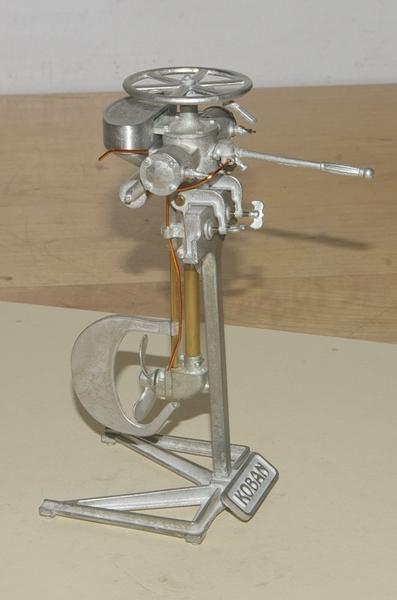
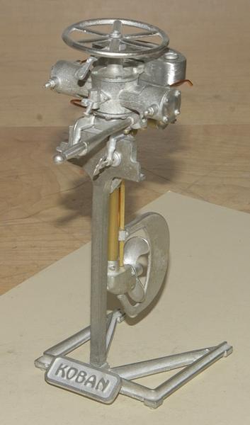
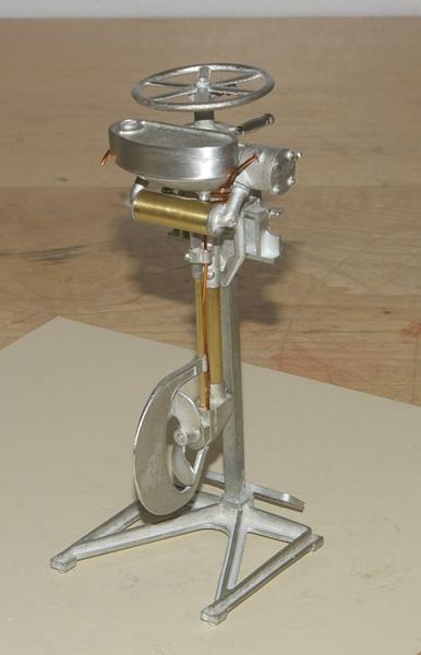
1 1:8 scale Koban Model Documentation Gear-foot assembly The gear foot consists of three parts, the gear-foot, prop shaft, and propeller. Clean flash from castings being careful to keep the mating surfaces of the prop and gear-foot flat. Trim the prop shaft about 1/32 inch and make sure that it is an easy fit into the prop. The large end of the prop shaft should be flush with the prop. Use a Dremel and a tiny drill to make a hole from the inside of the bottom rudder pivot hole to the prop shaft hole. This hole will allow glue to secure the prop shaft. When gluing the prop shaft be careful not to glue the prop.

2 Lower unit The lower unit consists of the parts in the picture. The brass parts are as follows: Shaft tube K&S 3/16 brass tubing long Rudder shaft is Special shapes or K&S brass 1/16 square stock long Large bush is.500 diameter X.202 inside diameter X.200 long 2 Small bushes are.250 diameter X.230 long with 2-56NC thread NC X1/4 long brass screws Cast parts include: Gear foot assembly rudder transom clamp 2 transom clamp screws 2 transom clamp screw pads flange rudder crank shaft and pivot casting Assembly insert the two small bushes (leave screws off) and glue into the shaft and pivot casting being

3 careful to keep the end flush with the casting and keeping glue out of the threaded hole. Place the shaft tube on the peg protruding from the shaft and pivot casting and glue in place. Insert peg on gear foot into shaft tube being careful to keep the gear foot aligned with the shaft and pivot casting. Glue in place. Smooth the outside of the rudder crank so that it is an easy fit into the hole in the shaft and pivot casting. Insert the bottom pivot of the rudder into the hole on the bottom of the gear foot. Thread the rudder shaft through the hole in the shaft and pivot casting through the hole at the top of the rudder and into the larger hole on the top of the gear foot. Push the rudder shaft through the hole in the shaft and pivot casting and over the rudder shaft. Glue the rudder shaft to the top hole in the rudder being sure that both the lower pivot and the rudder shaft are seated in the holes in the gear head. DO NOT GLUE THE RUDDER CRANK!

4 Screw the transom clamp screws into the transom clamp all the way. Screw the transom clamp pads onto the transom clamp screws being sure that the screw does not protrude beyond the pad. Apply a drop of glue to secure the pads to the screws. Position the transom clamp on the small bushes and screw to secure.

5 Set aside the lower unit, flange and large bush.
 Top crankcase bearing 1-72X1/4 or 1/72X3/16 NOTE Muffler length may vary due to variance of castings/holes. Suggest making 5 test mufflers with two.005 over/under, two.")
6 Crankcase The crank case assembly consists of : Crankcase/cylinders (one piece) 2 Cylinder heads Carburetor 2 Spark plugs Exhaust manifold 2 pcs Muffler - piece of K&S brass tube 11/32 X.014 X.950 long (see note) Top crankcase bearing 1-72X1/4 or 1/72X3/16 NOTE Muffler length may vary due to variance of castings/holes. Suggest making 5 test mufflers with two.005 over/under, two.010 over/under and one to.950 dimension. Check which test muffler fits and then cut appropriate size.


7 Prep and assembly: Clean up the ends of the cylinders and crankcase. Check to see that parts seat properly and that mating surfaces have been scratched with sandpaper or a file to assist bonding of glue. Using #1-72 taps thread the hole for the tiller. You may want to start with a spiral point tap and finish with a plug tap. Trim carburetor and spark plug pegs so that they do not protrude into the cylinder or crank holes. Test each to be sure. Position, align and glue the top bearing making sure the top gas tank mount is parallel with the mounting lug on the crankcase. Alignment is critical. Glue one of the exhaust manifolds to the brass tubing. Insert the other manifold into the tubing and fit the assembly into position on the crankcase. Glue the second manifold to the brass tube while in place. Remove the assembly from the crankcase and set aside. Fit and glue the cylinder heads Fit and glue the spark plugs in place. Using a # 60 or a #59 drill, drill the hole in the carburetor for the gas line. The #59 drill will provide a loose fit and the #60 a tight fit. Your choice. I would opt for the #59. Glue the carburetor in place.

8 Flywheel There are three flywheel options as shown in the picture. The flywheel with spokes, the magneto type flywheel with the knob, and the top hat wheel. The top hat and the magneto types use the advance lever with the coil plate. The wheel with spokes uses the smaller advance lever. The spoke wheel is pretty simple. Just clean it up and thread the crankshaft through it and the advance lever. The magneto wheel has a knob. Clean up the knob making sure the shaft fits the hole in the flywheel. The knob shaft is pushed into the hole till it bottoms out on the nut. The knob shaft is glued into the hole. The shaft is trimmed flush with the bottom surface of the flywheel The top hat wheel is made up of two parts. The flywheel needs to be filed flush to remove the nut and any bosses so that the rim will fit flush. The top of the flywheel then needs to be gently slid on 220 grit sandpaper on a flat surface to give glue tooth. The rim has two different sides. The top side does NOT have a raised bump. The bottom has a very small raised bump. Use a small chisel to remove the bump. Sand the central portion of the bottom surface to accept glue. Apply thick CA glue to the flywheel. Use a 1/8 dia. Teflon peg (included in with the flywheels) to center the rim onto the flywheel. Wipe off excess glue. Shoot with zip kicker.


9 Gas tank The gas tank consists of three parts. Top, bottom and gas cap. The top half needs to have the flash removed from the hole so that the gas cap fits and the sprues filed flush. The mating surfaces need to be scratched up with sand paper to aid glue adhesion. The bottom half of the gas tank needs to have the sprues filed down and the mating surfaces scratched up to aid in glue adhesion. DO NOT REMOVE THE EXTRA MATERIAL AROUND THE SHARP EDGE. Glue the top and bottom half together using medium or thick viscosity super glue. Shoot with zip kicker. Use Xeron flush cutters (model railway rail cutters) to nibble away the extra material leaving it just a bit larger than the top half of the tank. Then file or sand the extra material till it is flush with the side wall of the top half of the tank.


10 Assembly Drill one end of the steering link #53 and tap the other end of the link Use a 0-80X1/8 screw to connect the link to the tiller as shown. Position the large brass bushing in the crankcase flush with the bottom edge of the crankcase. Glue in place. Position the flange centered on the hole in the bushing. Use a piece of 18ga copper wire form the intake water tube. DO NOT GLUE IN PLACE. Set the water tube aside.

11 Clean up the flange and glue in place as shown being careful to keep the top surface of the flange perpendicular to the axis of the peg. Apply medium viscosity glue to the inside of the hole and surface of the brass bush and insert peg of lower unit and carefully/quickly align the lower unit with the crankcase. Fit the previously formed water tube to the crankcase and glue in place. Fit the rudder linkage and tiller and screw together. Holding the gas tank with the mating surface up, apply medium viscosity glue to the two recesses. Keeping the gas tank in that position fit the crankcase to it and allow glue to dry. Fit the lower water intake tube (18 gauge copper wire) and glue in place. Cut two pieces of 18 gauge copper wire for the exhaust water tubes and glue in place. Cut to desired length and bend the ends down. Bend about 1/8 of a length of 18 gauge copper wire 45 deg and insert into hole in bottom of gas tank. Bend and cut to form the gas line and insert the other end into the hole in the carburetor.
12
13

14
SDS Continental O-200 Installation Manual Aug. 4/17
 SDS Continental O-200 Installation Manual Aug. 4/17 This manual covers the steps to install the SDS EM-5 fuel injection and ignition system components on O-200 engines. Hall Sensor and Bracket Install
Backwater Performance Systems Large Vanguard Mikuni Twin Carburetor Kit
 Backwater Performance Systems Large Vanguard Mikuni Twin Carburetor Kit 1. Throttle Cable Twin (CKC-41) 2. Carburetor VM30mm (CKC-40) 3. Loctite 242.5mL (A-210) 4. Air Cleaner Filter 6000 (EC-86) 5. Rev
SERVICE BULLETIN. RS 307 May, Model change of EY15 and EY20 EY15-3, EY
 SERVICE BULLETIN RS 307 May, 200 MODEL EY5-3, EY20-3 SUBJECT Model change of EY5 and EY20 PURPOSE: To improve engine reliability, better sealing of governor shaft To renew engine design and color Reduction
EXTRA 330LX. Specifications: Code: SEA274. Graphics and specifications may change without notice. ASSEMBLY MANUAL
 ASSEMBLY MANUAL EXTRA 330LX Code: SEA274 Graphics and specifications may change without notice. Specifications: Wingspan---------------82.0 in (208.2 cm). Wing area---------------1349.4 sq.in ( 87.1 sq.dm).
CONCEPT MODELS WESTINGHOUSE SCHNABEL CAR 102/ Sheep Ranch Rd. Mountain Ranch, CA 95246
 CONCEPT MODELS http://www.con-sys.com//index.htm email:concept_models@con-sys.com 8331 Sheep Ranch Rd. Mountain Ranch, CA 95246 WESTINGHOUSE SCHNABEL CAR 102/301 2 CONCEPT MODELS Foreword As our name implies
Cut off saw - Starter assy and engine
 Cut off saw - Starter assy and engine Copyright Comet USA, Inc. 1/9/2015 1-13 Cut off saw - Starter assy and engine Ref.Nu Qty Part number Description Validity from Validity till Notes Bulletin 1 4 097000092AR
GM TRUCK Double Din Head Unit Install Kit
 www.thedetailss.com 95-99 GM TRUCK Double Din Head Unit Install Kit Please read all instructions including the *install tips* first! 1. Disconnect the vehicle s battery. 2. Remove the dash panel; Lower
Handle-bar and control box. ARTIK 56 EL
 Handle-bar and control box 1 Handle-bar and control box Reference Qty Item number Description 1 1 ZM000001 Handlebar 2 2 ZM000002 Lever 3 2 ZM000003 Cap 4 2 ZM000067 Lever connecting shaft 5 1 ZM000005
9/8/ MSHZ 2001 / TOP COWLING Yamaha Motor Corporation, U.S.A. All rights reserved.
 9.9MSHZ 00 Page of 47 9/8/04 9.9MSHZ 00 / TOP COWLING 04 Yamaha Motor Corporation, U.S.A. All rights reserved. 9.9MSHZ 00 Page of 47 9/8/04 Part List 9.9MSHZ 00 / TOP COWLING REF - NO PART NUMBER PART
$1.00 FOR THE TQIO/RCIO
 $1.00 FOR THE TQIO/RCIO m mm HDBBYSHOP Champion Jay Halsey has an impressive track record. One of Jay's advantages is a whisper smooth tranny thanks to his dad, Jim. Now you can build a Halsey transmission!
2010 Mustang V6 Shaker CDC #
 - - Incomplete 2010 Mustang V6 Shaker CDC # 1011-7002-01 Component Check List: Quantity/Description Part # Engine Cover Assembly 1011-6000-01 1 Engine Cover w/ Upper Air Tube 0511-2100-01 1 Aluminum Shaker
Craftsman Snow Thrower Model PARTS LIST
 Craftsman Snow Thrower Model 24.88955 11 13 3 26 24 9 1 18 54 6 25 15 20 23 16 5 14 1 55 9 4 4 28 8 30 2 5 56 35 36 46 3 39 50 53 43 38 48 52 42 51 41 40 49 4 44 31 45 31 21 29 34 9 19 10 32 22 26 Craftsman
Instruction Manual. Specification:
 Instruction Manual L O W Specification: Wingspan: 133 cm (52.3 inches) Length : 104 cm (40.9 inches) Weight : 1790gr Engine : 25-32 two stroke Radio : 4 channel - 4 servo W I N G KIT CONTENTS: We have
Instruction Manual book
 book ITEM CODE:BH 115. SPECIFICATION Wingspan : 6,000 mm 236,22 in. Length : 2,740 mm 107,87 in. Weight : 17.5kg 38.5Lbs. Radio : 08 channels. Servo : 07-08 HS-5685MH(HITEC) Battery : 2 Cells-Li-Po 7.4V
Door panel insert trim replacement Volvo V70
 Door panel insert trim replacement 1998-2000 Volvo V70 Tools needed: Torx Driver T25, Putty Knife, Bone Tool (optional), Heat gun or Dremel cutting tool, wire brush (or use a plastic tile and grout brush),
PARTS IDENTIFICATION AND ASSEMBLY INSTRUCTIONS
 The U.S. M10 ammunition trailer was used mostly by armored units to transport additional ammunition. It could be towed by many different vehicles, including 2 ½ ton trucks, half tracks, armored cars, self-propelled
RECOMMENDED MOTOR AND BATTERY SET UP
 SPECIFICATION - Wingspan: 1404mm (55.3in) - Length: 1134mm (44. 6 in) - Flying weight: 3.2-3.4 kg - Covering type: Genuine ORACOVER - Spinner size: scale type (not included) - Radio: 4 channel minimum
2005+ Roll Bar (Mm5RB-20.1 to -20.6) Recommended Center punch 1/8" pilot drill 1-3/4" Hole saw 2" Hole saw
 Recommended Center punch 1/8 pilot drill 1-3/4 Hole saw 2 Hole saw") 3430 Sacramento Dr., Unit D San Luis Obispo, CA 93401 Telephone: 805/544-8748 Fax: 805/544-8645 www.maximummotorsports.com 2005+ Roll Bar (Mm5RB-20.1 to -20.6) Recommended Center punch 1/8" pilot drill
3430 Sacramento Dr., Unit D San Luis Obispo, CA 93401 Telephone: 805/544-8748 Fax: 805/544-8645 www.maximummotorsports.com 2005+ Roll Bar (Mm5RB-20.1 to -20.6) Recommended Center punch 1/8" pilot drill
MiG-15 ARF Assembly & Operation Manual
 INLET PREP The MiG-15 inlet system has been accurately assembled at BVM. The following steps are required by the modeler prior to installation in the model. The inlet duct system is not glued into the
SIZE.120 OR 30CC SCALE 1:5 ARF
 PC21 PILATUS MK2 SIZE.120 OR 30CC SCALE 1:5 ARF SPECIFICATION - Wingspan: 1772mm (69.72in) - Length: 2019mm (79.5 in) - Flying weight: 6.4-7.2 kg - Wing area: 57.6 dm2 - Wing loading: 113g/dm2 - Wing type:
Holley GM LS1/2/6, LS3, and LS7 Hi-Ram Modular Intake Manifold Kits
 Holley GM LS1/2/6, LS3, and LS7 Hi-Ram Modular Intake Manifold Kits Holley P/N Engine Application & Induction Configuration 300-112 LS3 Hi-Ram, Carbureted, 2 x 4500 Dominator, 2 throttle bores (sideways
3 October 2016 PN# V Dodge Twin Turbo Kit (I-00274) ½ D o d g e 2 4 v I S B
 ½ D o d g e 2 4 v I S B") 3 October 2016 PN#1045320 24V Dodge Twin Turbo Kit (I-00274) 1 DOWNLOAD ENHANCED INSTALL MANUALS AT dieselperformance.com BD Twin Turbo Kit 1998½- 2 0 0 2 D o d g e 2 4 v I S B Part# 1045320 PLEASE READ
3 October 2016 PN#1045320 24V Dodge Twin Turbo Kit (I-00274) 1 DOWNLOAD ENHANCED INSTALL MANUALS AT dieselperformance.com BD Twin Turbo Kit 1998½- 2 0 0 2 D o d g e 2 4 v I S B Part# 1045320 PLEASE READ
9/7/2014 F9.9MSHV 1997 / CYLINDER CRANKCASE Yamaha Motor Corporation, U.S.A. All rights reserved.
 F9.9MSHV 997 Page of 45 9/7/04 F9.9MSHV 997 / CYLINDER CRANKCASE 04 Yamaha Motor Corporation, U.S.A. All rights reserved. F9.9MSHV 997 Page of 45 9/7/04 Part List F9.9MSHV 997 / CYLINDER CRANKCASE REF
5/29/2014 3MSHU 1996 / CYLINDER CRANKCASE Yamaha Motor Corporation, U.S.A. All rights reserved.
 Page 1 of 22 3MSHU 1996 / CYLINDER CRANKCASE Page 2 of 22 Part List 3MSHU 1996 / CYLINDER CRANKCASE REF - NO PART NUMBER PART NAME QUANTITY REMARKS 1 6L5-W0090-01-4D CRANK CYLINDER ASSEMBLY 1 2 6L5-15100-00-94
5/29/2014 3MSHY 2000 / CYLINDER CRANKCASE Yamaha Motor Corporation, U.S.A. All rights reserved.
 Page 1 of 22 3MSHY 2000 / CYLINDER CRANKCASE Page 2 of 22 Part List 3MSHY 2000 / CYLINDER CRANKCASE REF - NO PART NUMBER PART NAME QUANTITY REMARKS 1 6L5-W0090-01-1S CRANK CYLINDER ASSY 1 2 6L5-15100-00-1S
WING ASSEMBLY SECTION 13 INSTALLING FUEL TANKS AND RIVETING THE WING SKINS CLOSED
 WING ASSEMBLY SECTION 13 INSTALLING FUEL TANKS AND RIVETING THE WING SKINS CLOSED Compass Check 1. Measure the location of the tank outlets. 2. Install supports. 3. Cut the holes in the skin and ribs for
REF. NO. DESCRIPTION TOP COWLING 2 MOLDING, AIR DUCT 3 RIVET 4 SEAL 5 HOLDER, CLAMP BAND 6 BOLT, WITH WASHER 7 HOOK
 SUZHOU ALLPASS MACHINERY CO.,LTD Add:No.85,Jishui Road,Jinfeng Industrial Park,Mudu Town,Suzhou 215102,Jiangsu,P.R.China T15 SPARE PARTS EXPLODED DRAWING FIG. 1 1 TOP COWLING TOP COWLING 2 MOLDING, AIR
Illustrated Parts List Industrial/Commercial to
 FORM MS-9479 6/95 REPLACES FORM MS-9479 10/94 FILE IN SECT. 2 OF SERVICE MANUAL 402700 to 402799 Illustrated Parts List Industrial/Commercial Model Series 402700 to 402799 TYPE NUMBERS 1115 through 1117,
rev 1_09/20/2017 PS-35C EA3500SR
 C 1 Tank, Handle 5 7 6 8 17 9 1 2 10 11 12 13 18 19 20 3 21 4 22 23 14 16 2 1 Tank, Handle 1 1 168507-3 TANK CAP COMPLETE 1 1 INC. 2 1 2 213080-9 O RING 29.5 1 1 1 3 163447-0 GASOLINE FILTER 1 1 1 4 195757-7
SPARE PARTS LIST. POWER CUTTERS K960 Chain,
 SPARE PARTS LIST POWER CUTTERS K960 Chain, 2008-03 AIR FILTER K960 Chain, 2008-03 AIR FILTER K960 Chain, 2008-03 Ref Part No Description Remark QTY KIT 1 503 21 53-45 SCREW ITXSCM 2 2 544 87 46-01 LABEL
INSTALLATION INSTRUCTIONS
 INSTALLATION INSTRUCTIONS ----3300 W. Pontiac Way Clovis, CA 93612 toll free: 1-800-445-3767 web: www.belltech.com---- 6605-6607 FLIP KIT CHEVROLET C/K 1500 / 2500 PICK UP Thank you for being selective
Build the. Steam Locomotive. Pack 01
 Build the Steam Locomotive Pack 01 Build the Steam Locomotive Contents Step by step Stage 01: The smokebox door Stage 02: The smokebox Stage 03: The first driving wheels and coupling rods Stage 04: The
I n s t r u c t i o n M a n u a l. Instruction Manual SPECIFICATION
 I n s t r u c t i o n M a n u a l Instruction Manual SPECIFICATION - Wingspan: 3200mm (125,9 in) - Length: 1650mm (64,9 in) - Flying weight: 3000gr 3200gr - Wing area: 64.5 dm2 - Wing loading: 46g/dm2
Table of Contents. Tail Wheel Assembly Installation.. page 01. Stabilizer Installation.. page 02. Fin Installation.. page 03
 Table of Contents Tail Wheel Assembly Installation.. page 01 Stabilizer Installation.. page 02 Fin Installation.. page 03 Elevator and Rudder Hinge Installation.. page 04 Rudder Controls.. page 05 Elevator
Instructions for Assembling Driving Wheels, Axles and Crankpins
 Instructions for Assembling Driving Wheels, Axles and Crankpins (Version 1; October 2008) Introduction These instructions explain how to assemble Exactoscale 4mm scale driving wheels, axles and crankpins
Illustrated Parts List. Model Series AIR COOLED
 FORM MS6154--06/10/2010 REPLACE FORM MS6154--03/06/2010 FILE IN SECT. 2 OF SERVICE MANUAL Illustrated Parts List Model Series AIR COOLED TYPE NUMBERS 0035, 0038, 0048, 0076, 0078, 0079, 0100, 0111, 0113,
Truckmount Repairs Cat 290 Pump Repair
 Cat 290 Pump Repair COMMON STOCKED PARTS 3 PST101802 Cylinder CAT 290 3 PST26112 Cylinder CAT 280 1 PHY027-004 Oil Filler Cap Black (old 280 & 290 s) 1 PST43211 Oil Filler Cap - Red 1 PST14177 O-ring Oil
R O A D S M I T H TRIKE CONVERSIONS BY THE TRIKE SHOP
 R O A D S M I T H TRIKE CONVERSIONS BY THE TRIKE SHOP Please thoroughly review the instructions before and during installation. Keep in mind that this product was designed to be installed by trained dealer
Page 1 of HP B&S Vanguard Engine
 1405 Page 1 of 41 14 HP B&S Vanguard Engine 1405 Page 2 of 41 14 HP B&S Vanguard Engine Ref # Part Number Qty S/P/F Description BS-28Q777-0647-E1 1 14 HP B&S Vanguard Engine 1 BS-496412 1 Cylinder Assembly
DESCRIPTION FUEL AND VACUUM PUMP REMOVE AND REPLACE FUEL PUMP-OVERHAUL 6B PONTIAC SHOP MANUAL. S. Install battery and connect cables.
 6B-74 1955 PONTIAC SHOP MANUAL DESCRIPTION FUEL AND VACUUM PUMP All models are equipped with a combination fueland double acting vacuum pump operated by an eccentric bolted to the front end of the engine
613GC Key A Parts Starter & Ignition Assembly
 613GC Key A Parts Starter & Ignition Assembly 73866 Screw (same as B26) A01 505514 Starter Rope Handle A02 73904 Starter Rope A03 73909 Starter Coil Spring & Housing A04 71451 Starter Case Plate A05 73910
Heljan EM Finescale Conversion.
 Heljan 02 2-8-0 EM Finescale Conversion. Before you start, it is a good idea to have some small containers or snap top poly bags to put screws and components in for safe keeping...much better than crawling
Illustrated Parts List
 01/08/2010 FILE IN SECT. 2 OF SERVICE MANUAL PRO DRIVE 613777-0113 -E1 Illustrated Parts List Model Series AIR COOLED 613777 TYPE NUMBERS 0113. TABLE OF CONTENTS Air Cleaner... Alternator... Blower Housing/Shrouds...
Illustrated Parts List
 FORM MS 3745 12/21/2006 FILE IN SECT. 2 OF SERVICE MANUAL 613700 Illustrated Parts List Model Series 613700 TYPE NUMBERS 0110. TABLE OF CONTENTS Air Cleaner......................... 6 Alternator..........................
Illustrated Parts List. Model Series 10T500. TYPE NUMBERS 0001 through TABLE OF CONTENTS. Air Cleaner... 6 Blower Housing/Shrouds...
 Illustrated Parts List Model Series 10T500 TYPE NUMBERS 0001 through 3840. FORM MS3718 REV T 11/29/2012 REPLACES FORM MS3718 REV S 10/22/2012 FILE IN SECT. 2 OF SERVICE MANUAL 10T500 TABLE OF CONTENTS
MS:124 ASSEMBLY MANUAL. Graphics and specifications may change without notice.
 ASSEMBLY MANUAL MS:124 Graphics and specifications may change without notice. Specifications: Wing span ------------------------------65in (165cm). Wing area -----------------658.8sq.in (42.5sq dm). Weight
Illustrated Parts List to
 TYPE NUMBERS 0101, 0102, 0106, 0108, 0109, 0115 through 0224, 0415, 0418, 0467, 0468, 0601 through 0683, 3101 through 3108, 3110 through 3163, 3167 through 3181. Illustrated Parts List Model Series 124700
***FOR COMPETITION USE ONLY as per US EPA regulations *** Factory Pipe Bill of Materials Kawasaki Ultra 150 Triple Pipe
 ***FOR COMPETITION USE ONLY as per US EPA regulations *** Factory Pipe Bill of Materials Kawasaki Ultra 150 Triple Pipe Item Qty Part Number Part Description 1 1 COMASM0947 Ultra 150 PTO Chamber assembly
MS:176 ASSEMBLY MANUAL. Graphics and specifications may change without notice.
 ASSEMBLY MANUAL MS:176 Graphics and specifications may change without notice. Specifications: Wing span ------------------------------98.4in (250cm). Wing area ----------------1576.4sq.in (101.7sq dm).
Replacement Parts & Accessories Price List
 Replacement Parts & Accessories Price List 633GC / 633F4 Gas Concrete Saws Effective January 1, 20167 TABLE OF CONTENTS 633GC / 633F4 Gas Saws ITEM DESCRIPTION KEY PAGE 633GC / 633F4 Gas Saw Service Items
MS:136 ASSEMBLY MANUAL. Graphics and specifications may change without notice.
 ASSEMBLY MANUAL MS:136 Graphics and specifications may change without notice. Specifications: Wing span ----------------------------79.5in (202cm). Wing area -----------------965.7sq.in (62.3sq dm). Weight
rev 2_ EA6100P53G (Makita Teal) EA6100PR (Makita Red) PS-6100 (Dolmar Red) PS-6100H (Dolmar Red)
 EA6100PR (Makita Red) PS-6100 (Dolmar Red) PS-6100H (Dolmar Red)") (Makita Teal) (Makita Red) (Dolmar Red) (Dolmar Red) 1 Tank, Handle USA 168 24 12 125 22 20 100 108 23 11 25 127 A 88 123 21 58 130 67 9 3 4 65 67 118 66 61 118 100 26 59 60 167 109 109 2 1 Tank, Handle
(Makita Teal) (Makita Red) (Dolmar Red) (Dolmar Red) 1 Tank, Handle USA 168 24 12 125 22 20 100 108 23 11 25 127 A 88 123 21 58 130 67 9 3 4 65 67 118 66 61 118 100 26 59 60 167 109 109 2 1 Tank, Handle
Flyzone Spitfire FF to R/C Conversion Instructions
 Flyzone Spitfire FF to R/C Conversion Instructions Hobbico Flyzone EP FF airplanes have been around for years, with exciting new models being added constantly. The recent interest shown by R/C modelers
1660mm (65.4 in) 1200mm (47.2 in) 2700gr gr 6 channel - 7 servo standard 46/ 2 stroke or 52/ 4 stroke
 1200mm (47.2 in) 2700gr gr 6 channel - 7 servo standard 46/ 2 stroke or 52/ 4 stroke") Instruction Manual CESSNA-46 1660mm (65.4 in) 1200mm (47.2 in) 2700gr - 3000gr 6 channel - 7 servo standard 46/ 2 stroke or 52/ 4 stroke KIT CONTENTS: We have organized the parts as they come out of the
Instruction Manual CESSNA-46 1660mm (65.4 in) 1200mm (47.2 in) 2700gr - 3000gr 6 channel - 7 servo standard 46/ 2 stroke or 52/ 4 stroke KIT CONTENTS: We have organized the parts as they come out of the
H8190 Pump Parts Breakdown
 H8190 Pump Parts Breakdown -30- H8189/H8190 Gasoline Pressure Washer H8190 Pump Parts List 1 PH8189001 CRANK CASE COVER BOLT 51 PH8189051 VALVE JACKET INNER GASKET 2 PH8189002 OIL DRAIN PLUG 52 PH8189052
SDS Continental IO-550 Installation Manual
 SDS Continental IO-550 Installation Manual July14/18 This manual covers the steps to install the SDS EM-5 fuel injection and ignition system components on IO-550 engines. Checking Clearance for Hall Sensor
MR-1. Please read and understand all instructions before building!
 MR-1 This kit contains all the parts necessary* to build a flying high power rocket: (1) Pre-slotted main airframe (1) Nose cone with strap (3) Fins (1) Transition (1) Airframe section 1 long (1) Piston
Instruction Manual book
 Instruction Manual book Item code:bh117 SPECIFICATION Wingspan : 2,100 mm 82.68 in. Length : 1,875 mm 73.82 in. Weight : 7.5 kg 16.5 Lbs. Radio : 08 channels. Servo : 09 servos. Engine : 33-45cc gas. Made
Chevrolet 3100 IFS Kit
 1947-54 Chevrolet 3100 IFS Kit Congratulations on your purchase on what we believe is the finest IFS kit available for 1947-54 Chevrolet pickups with stock frames. We have invested many hours into designing
Remove Air Cleaner Cover and. Filter
 Remove Air Cleaner Cover and Inspect paper filter for tears Foam pre-cleaner is washable if equipped Replace if necessary Filter Remove Trim Panel Pull throttle lever knob off Remove 3, 8mm screws Remove
Model No. EA6100P PETROL CHAIN SAW
 1 / 6 2 / 6 3 / 6 4 / 6 5 / 6 6 / 6 1 / 5 Item Parts No. Description I/C Qty N/O Sales Purch. Note 001 181114202 TANK CAP CPL. 1 D10 INC. 2 002 963229036 PACKING RING 1 003 908006145 FILLISTER HEAD SCREW
ATV 50 Y-6 YOUTH CAT GREEN (A2004ATA2BUSZ) Page 1 of 50 A-ARM, FLOOR PANEL, AND BUMPER ASSEMBLY
 Page 1 of 50 A-ARM, FLOOR PANEL, AND BUMPER ASSEMBLY") 2004 ATV 50 Y-6 YOUTH CAT GREEN (A2004ATA2BUSZ) Page 1 of 50 A-ARM, FLOOR PANEL, AND BUMPER ASSEMBLY 2004 ATV 50 Y-6 YOUTH CAT GREEN (A2004ATA2BUSZ) Page 2 of 50 A-ARM, FLOOR PANEL, AND BUMPER ASSEMBLY
2004 ATV 50 Y-6 YOUTH CAT GREEN (A2004ATA2BUSZ) Page 1 of 50 A-ARM, FLOOR PANEL, AND BUMPER ASSEMBLY 2004 ATV 50 Y-6 YOUTH CAT GREEN (A2004ATA2BUSZ) Page 2 of 50 A-ARM, FLOOR PANEL, AND BUMPER ASSEMBLY
REVISION DESCRIPTION:
 REVISION DESCRIPTION: 1) Page: 12-03 REV 1: Step 1: and Figure 1: Final-Drill s.b. Match-Drill. Step 4: Updated flox mixture description to match later description (removed "peanut butter-like" description).
AIRCRAFT LANDING GEAR CONSTRUCTION MANUAL
 APPENDIX AI KITPLANES FOR AFRICA AIRCRAFT LANDING GEAR CONSTRUCTION MANUAL Revision: C September 2008 Page L1 of 20 NOTE: Please read the General Manual before proceeding. Please read through the entire
Instruction Manual. Wingspan : 1884 mm (74.17 in) Length. Weight. Engine. : 4 channels / 5 servo standard. : 1450 mm (57.
 Length. Weight. Engine. : 4 channels / 5 servo standard. : 1450 mm (57.") Wingspan : 1884 mm (74.17 in) Length : 1450 mm (57.09 in) Weight : 4000 gr Engine : 60 two strokes Radio : 4 channels / 5 servo standard KIT CONTENTS: We have organized the parts as they come out of the
Wingspan : 1884 mm (74.17 in) Length : 1450 mm (57.09 in) Weight : 4000 gr Engine : 60 two strokes Radio : 4 channels / 5 servo standard KIT CONTENTS: We have organized the parts as they come out of the
Piranha 3D Hydro Plane
 Piranha 3D Hydro Plane Dear customer, congratulations on the purchase of the Pirañha model. To enjoy building and flying the model most, please read carefully the building instructions before you begin
Illustrated Parts List
 FORM MS 4183 10/31/2006 REPLACES FORM MS 9748 7/1997 FILE IN SECT. 2 OF SERVICE MANUAL 290700 Illustrated Parts List Model Series 290700 TYPE NUMBERS 0100, 0102, 0106, 0107, 0108, 0333, 0402, 0410. TO
90 Y-12 Youth. Model Number A2005H4B2BUSR (Red) Model Number A2005H4B2BUSZ (Cat Green) Illustrated Parts Manual
 Model Number A2005H4B2BUSZ (Cat Green) Illustrated Parts Manual") 90 Y-12 Youth Model Number A2005H4B2BUSR (Red) Model Number A2005H4B2BUSZ (Cat Green) Illustrated Parts Manual 2005 TABLE OF CONTENTS 2005 ATV 90 Y-12 Youth Red (Model No. A2005H4B2BUSR) Cat Green (Model
90 Y-12 Youth Model Number A2005H4B2BUSR (Red) Model Number A2005H4B2BUSZ (Cat Green) Illustrated Parts Manual 2005 TABLE OF CONTENTS 2005 ATV 90 Y-12 Youth Red (Model No. A2005H4B2BUSR) Cat Green (Model
Replacement Parts & Accessories Price List
 Replacement Parts & Accessories Price List 613GC Gas Concrete Saw Effective January 1, 2010 SERVICE ITEMS 613GC Gas Concrete Saw Above 71700 Gas Saw Service Tool Kit, includes all items shown above $668.00
Owner s Manual PARTS LISTING
 Owner s Manual PARTS LISTING 35 Cylinder head system assy. SP-GG350-A-01-JD CYLINDER HEAD COMP. JF200-A-01 SP-GG350-A-02-JD EX. VALVE GUIDE JF168-A-02 SP-GG350-A-03-JD IN. VALVE GUIDE JF168-A-03 SP-GG350-A-04-JD
Reproduction. Not for. Illustrated Parts List 44S700. Model Series TYPE NUMBERS 0001 THROUGH 0003, 0005, 0007, 0009, 0011, 0013 THROUGH 0020.
 FORM MS10464 REV B 06/03/2016 MS10464 REV A 06/10/2015 FILE IN SECT. 2 OF SERVICE MANUAL 44S700 Illustrated Parts List Model Series 44S700 TYPE NUMBERS 0001 THROUGH 0003, 0005, 0007, 0009, 0011, 0013 THROUGH
PARTS REQUIRED. Engine Mount. Engine Mount Special Tool. Flywheel Bolts
 Campaign no.: 2008 0009 December 5, 2008 Subject:Flywheel Bolts & Engine Mount. No. 2008-6 YEAR MODEL MODEL NUMBER SERIAL NUMBER 2008 DS 450 DS 450 X All See attached list NOTE: Repair all vehicles in
Illustrated Parts Manual
 Illustrated Parts Manual Cub Cadet 700 Series VTT CUB CADET LLC, P.O. BOX 361131 CLEVELAND, OHIO 44136-0019 Printed In USA Form No. 769-10183 (September 8, 2014) To The Owner Thank You Thank you for purchasing
Norden. A Lancashire Mill Engine. Scale: 1:12
 Scale: 1:12 Neil M. Wyatt February 2009 Fig. 1: General Arrangement General Arrangement Sheet: 1 An Old Steam Engine DEAR SIR, In the ruins of an old mill at, near Rochdale, there is an old steam engine
AJV8 Engine Assembly. AJV8 Engine Assembly
 AJV8 Engine Assembly Contents Cylinder Block Dowels, Plugs and Pipes 2 4 Crankshaft Bearing and Cylinder Bore Dimensions 5 9 Bearing Measuring 6 Engine Dimensions and Codes 6 7 Main Bearing Selection Chart
Stephenson's Valve Gear: 7mm cast white-metal kit 19 th Century swing-link version - non-working, cosmetic only. Instructions
 SER-Kits Stephenson's Valve Gear: 7mm cast white-metal kit 19 th Century swing-link version - non-working, cosmetic only Page 1 of 5 Instructions HEALTH & SAFETY: The castings contain some lead. Dispose
INSTALL MANUAL D o d g e 1 2 v 6 B T A PLEASE READ ALL INSTRUCTIONS BEFORE INSTALLATION.
 PN#1045310 12V Dodge Twin Turbo Kit (I-00273) 1 INSTALL MANUAL BD Twin Turbo Kit 1994-1 9 9 8 D o d g e 1 2 v 6 B T A Part# 1045310 PLEASE READ ALL INSTRUCTIONS BEFORE INSTALLATION. * Picture as shown
9/7/2014 T9.9ELRZ 2001 / TOP COWLING Yamaha Motor Corporation, U.S.A. All rights reserved.
 T9.9ELRZ 00 Page of 56 9/7/0 T9.9ELRZ 00 / TOP COWLING 0 Yamaha Motor Corporation, U.S.A. All rights reserved. T9.9ELRZ 00 Page of 56 9/7/0 Part List T9.9ELRZ 00 / TOP COWLING REF - NO PART NUMBER PART
Contents. Preparing the motor Winding the rotating secondary Winding the primary... 8
 120732-130389 Propeller Clock Construction Notes Revision E, December 2, 2013 Contents Preparing the motor... 2 Winding the rotating secondary... 5 Winding the primary... 8 UltiProp Clock (Elektor Dec.
Holley Ford 351W Hi-Ram Modular Intake Manifold Kits
 Holley Ford 351W Hi-Ram Modular Intake Manifold Kits Holley P/N Engine Application & Induction Configuration 300-241 Hi-Ram, 1 x 95mm LS Throttle Body (longitudinal mount) w/ port EFI provisions & fuel
Instruction Manual book
 book SPECIFICATION Wingspan : 2,310 mm 90.94 in. Length : 1,750 mm 68.90 in. Weight : 8.4 kg 18.48 Lbs. Radio : 06 channels. Servo : 09 servos + 2 mini servos (elevator). Engine : 45-55CC gas. Made in
Cylinder Assy. (2-1/2" Bore) (Cast-iron Pin, Dowel Plug, Drain Seal, Oil A 0 Valve, Intake (Standard)
 (Cast-iron Pin, Dowel Plug, Drain Seal, Oil A 0 Valve, Intake (Standard)") H35-45234F Page 1 of 8 H35-45234F Page 2 of 8 1 31270 0 Cylinder Assy. (2-1/2" Bore) (Cast-iron 2 26727 0 Pin, Dowel 3 27642 0 Plug, Drain 3A 27642 0 Plug, Drain 4 29183 0 Seal, Oil 5 29314A 0 Valve, Intake
H35-45234F Page 1 of 8 H35-45234F Page 2 of 8 1 31270 0 Cylinder Assy. (2-1/2" Bore) (Cast-iron 2 26727 0 Pin, Dowel 3 27642 0 Plug, Drain 3A 27642 0 Plug, Drain 4 29183 0 Seal, Oil 5 29314A 0 Valve, Intake
For Discount Tecumseh Engine Parts Call or HH E Page 1 of 8 Engine Parts List #1
 HH60-105080E Page 1 of 8 Engine Parts List #1 HH60-105080E Page 2 of 8 Engine Parts List #1 1 34761 0 Cylinder Assy. (Cast iron liner) (2-5/8" 2 27652 0 Pin, Dowel 3 27642 0 Plug, Drain 4 27876B 0 Seal,
Chainsaw Emak S.p.A.
 Chainsaw - Engine Meccanografico RE 005145 C/C Postale 11178423 Partita IVA 00130010358 Codice Fiscale 00130010358 1 / 18 Meccanografico RE 005145 C/C Postale 11178423 Partita IVA 00130010358 Codice Fiscale
EVO-1085 JK DoubleD Long Arm Upgrade. EVO /37 JK DoubleD LongArm Kit
 EVO-1085 JK DoubleD Long Arm Upgrade EVO-1084-35/37 JK DoubleD LongArm Kit (EVO-1084 pictured above with Bilstein 5100 Shocks and optional EVO HD Swaybar Endlinks) NOTES: Cutting and grinding is required
HKS 700E. Service Manual June Ver. 2.04
 HKS 700E Service Manual 009 June Ver..04 HKS CO.,LTD 78 KITAYAMA FUJINOMIYA SHIZUOKA JAPAN 48-09 TEL +8(0)544-54-78 FAX +8(0)544-54-40 hks_aviation@hks-power.co.jp http://www.hks-power.co.jp/hks_aviation/
Instruction Manual book
 book ITEM CODE: BH99. SPECIFICATION Wingspan : 2,850 mm 112.20 in. Length : 1,910 mm 75.20 in. Weight : 8.1 kg 17.82 Lbs. Radio : 06 channels. Servo : 08 servos. Engine : 35 CC gas. Made in Vietnam. This
RS04 RS16 RS19 RS18 PHOTOETCHED: CAST: DECALS: SCREWS: OTHER: - RS02 RS03 RS04 RS05 RS08 RS09 RS16 RS18 RS19 M23. 8x T03
 PART 2 chapter 3 building steps 2 A1 Engine/gearbox casing Cyanacrylate () sand paper RS19 RS04 RS16 RS02 RS09 RS08 RS05 RS03 Stick together the crankshaft casing as gap-free as possible from the designated
MS:183 ASSEMBLY MANUAL. Graphics and specifications may change without notice.
 MS:183 ASSEMBLY MANUAL Graphics and specifications may change without notice. Specifications: Wing span ------------------------------79.9in (203cm). Wing area -----------------1165.6sq.in (75.2sq dm).
SAN FELIPE: Step by Step Pack 8
 Pack 8 Your parts Gun port frames Complete gun ports Tools and equipment Tweezers Superglue Pliers Hammer Sandpaper Wood stain Paintbrushes Black pen a Glue gun port frames to the gun ports of the main
ASSEMBLY MANUAL. Specifications
 ASSEMBLY MANUAL MS: SEA 82 Graphics and specfications may change without notice. Specifications Wingspan-------------------------------------- 70.9 in------------------------------ 180cm. Wing area-------------------------------------
Super EZ Chain Saw UT Page 1 of 18 Tools And Accessories
 Super EZ Chain Saw UT-10440 Page 1 of 18 Tools And Accessories Super EZ Chain Saw UT-10440 Page 2 of 18 Tools And Accessories 24299 24299 ANVIL- Crankshaft installation 24304 24304 BIT- #2 pozidrive 24295
Owner s Manual. Parts List. Cylinder Head assy. APA Part No. Description Part. No
 Cylinder Head assy. A SP-GG900E-A-01-JD HEAD COVER COMP. BOLT JF340-A-01 SP-GG900E-A-02-JD HEAD COVER WASHER COMP. JF340-A-02 SP-GG900E-A-03-JD TUBE JF340-A-13 SP-GG900E-A-04-JD HEAD COVER COMP. JF340-A-04
INSTALLATION INSTRUCTIONS 97 FORD EXPEDITION
 INSTALLATION INSTRUCTIONS 97 FORD EXPEDITION 1. Read the instructions completely and carefully before you begin. Check the kit for proper contents (refer to the part s list and the picture diagrams). Before
Illustrated Parts List
 FORM MS 0323 6/27/2003 REPLACES FORM MS 0323 4C 9/2001 FILE IN SECT. 2 OF SERVICE MANUAL 93400 Illustrated Parts List Model Series 93400 TYPE NUMBERS 0010 through 1278. TABLE OF CONTENTS Air Cleaner.........................
5/30/2014 F2.5MSH 0407 / TOP COWLING Yamaha Motor Corporation, U.S.A. All rights reserved.
 F.5MSH 0407 Page of 40 5/30/04 F.5MSH 0407 / TOP COWLING 04 Yamaha Motor Corporation, U.S.A. All rights reserved. F.5MSH 0407 Page of 40 5/30/04 Part List F.5MSH 0407 / TOP COWLING REF - NO PART NUMBER
Model No. EK8100 POWER CUTTER
 1 / 7 2 / 7 3 / 7 4 / 7 5 / 7 6 / 7 7 / 7 1 / 5 Item Parts No. Description I/C Qty N/O Opt. 1 Opt. 2 Note 001 168507-3 TANK CAP COMPLETE 1 D10 INC. 2 002 213080-9 O RING 29.5 1 003 163499-1 SUCTION HEAD
EVO-1162 EVO Tailgate Tire Carrier
 EVO-1162 EVO Tailgate Tire Carrier Bill of Materials EVO-1162 Tailgate Tire Carrier Part number Description Quantity EVO-12161 EVO Tailgate Tire Carrier 1 EVO-12162 Bolt Plate 1 EVO-12163 Wheel Mount 1
Illustrated Parts List to 95999
 TYPE NUMBERS 0100, 0101, 0102, 0106 through 0115, 0117 through 0126, 0128 through 0139, 0206, 0207, 0210, 0215 through 0229, Illustrated Parts List Model Series 95900 to 95999 FORM MS 2413 8/97 REPLACES
Instruction Manual book
 book SPECIFICATION Wingspan : 1,450 mm 57.09 in. Length : 1,200mm 47.24in. Weight : 3.1 kg 6.82 Lbs. Radio : 05 channels. Servo : 07 servos. Engine : 61-75 2 stroke. 91 4 stroke. Made in Vietnam. This