SDS Continental IO-550 Installation Manual
|
|
|
- Suzan Anderson
- 5 years ago
- Views:
Transcription


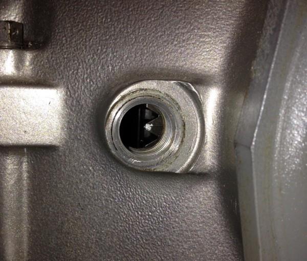
1 SDS Continental IO-550 Installation Manual July14/18 This manual covers the steps to install the SDS EM-5 fuel injection and ignition system components on IO-550 engines. Checking Clearance for Hall Sensor Bracket to Crankcase It may be necessary on some engines to file the uppermost front case split boss slightly to be sure it clears the Hall bracket. See the photo below. Run a straight edge up vertically from the crankshaft seal retainer plate front face. If the straight edge clears the crankcase boss, no action is required. If not, file just enough material from the front boss face to allow clearance. Hall Sensor and Bracket Install the red Hall sensor to the supplied bracket using the Allen head hardware and lock washers supplied. Tighten to inch pounds. Remove the two AN3 upper crankshaft seal retaining plate bolts. If you have sheet metal baffling attached here, drill two.375 holes to clear the raised thread bosses on the Hall mount (right). Place one washer under the bolt heads against the bracket and insert bolts through the bracket and seal retainer into the engine case. Torque to inch pounds.

2 Install the supplied fire sleeve over the sensor cables. Magnet Mounting The magnets are mounted into holes you will drill into 4 of your 6 prop bolt ends using the split bushing fixture supplied in the kit. Slide the prop bolts into the bushing and clamp tightly in a lathe chuck. Drill about.187 deep into the bolt end using a #30 drill. Clean the chips away and insert a magnet to check for about.050 protrusion past the bolt end. Carefully drill incrementally deeper until you get the magnet to protrude this distance. Repeat on 3 of the other bolts. Using the drilling sleeve to clamp prop bolt in lathe chuck Clean the bolt holes and tips with compressed air and acetone so they are free of chips and oil. Mix up a small amount of 5 minute epoxy and using a piece of 1/16 welding rod, insert a small amount of epoxy into the bolt holes. Using a piece of wooden doweling or aluminum stock (non ferrous material), push 3 of the magnets into the holes with the blue end facing out and one magnet with the blue end facing into the bolts. You should have a small meniscus of epoxy surrounding the magnet. Prop Bolt Placement Place the crankshaft with the TC mark aligned with the LOWER crankcase split. Note the position of the bolts in relation to the TC mark on the prop flange edge.
.")

3 The ones marked T are for the 3 trigger magnets (blue end facing out). The one marked S is for the synch magnet (blue end facing into the prop bolt). Magnet/ bolt placement on crank flange with crank at TDC 1 Some engines lack TDC marks on the hub. See the last page for alternate TDC method. NOTE: T/C MARK LINES UP WITH LOWER CASE SPLIT. Magnet Air Gap

4 You should aim for air gap between the tip of the magnets and the red Hall Effect sensor face. Use washers under the prop bolt heads to achieve this distance. Fuel Block Remove the 2 front most top crankcase through bolts as shown the in photo below. Replace the stock bolts with the longer, supplied ones using one washer under the head, then slide the bracket over the bolts, then one more washer against the case and then the nuts. Torque to in lbs. Screw in the supplied fittings as desired using a SMALL amount of Teflon pipe sealant compound Just enough to fill the threads of the fittings). NEVER use silicone (RTV) for sealing fittings! Tighten the fittings until snug and orientated as desired. Fuel should enter one end of the block through the AN6 fitting and head to the regulator from the AN6 fitting on the other end. There is provision for a fuel pressure takeoff as well.


5 Fuel Injector Mounting Locate the weld-on injector bosses near the ports on each intake runner in turn so that you have clearance to the cowling and room for the fuel fittings and injector electrical connectors. Using a Sharpie marker through the center of the boss, mark the central point on the runner. Pilot drill the mark with a 1/8 drill and then enlarge the hole with a step drill to 3/8. Use a 13/32 twist drill to oval the hole to match the injector boss footprint by
, tighten and orientate as desired.")
6 standing the drill up to a 45 degree angle. File and deburr the hole to match the injector boss shape. Tig weld each boss in place. See a tutorial here: Install the 90 degree fuel fittings into the injector top caps with Teflon thread sealant (Never RTV), tighten and orientate as desired. Coil Pack Mounting The coil packs mount in place of the magnetos. Bolt the coil pack bracket to the magneto covers using the bolts provided. Torque to inch lbs. And either use 292 blue Locktite or lockwire to secure the bolts. Please note, you must remove the magneto gears and cannot use the rear accessory drives since these are driven by the mag gears. You must also turn the accessory shaft cover plates 90 degrees to seal off the oil holes for the shafts. Apply a LIGHT coating of RTV on the cover faces or use new magneto gaskets. Install the clamps and nut hardware to secure the coil packs. They may be rotated slightly for clearance from other obstructions. Tighten the nuts to inch lbs.

7 Spark Plug Adapters SDS supplies brass 18 to 14mm plug adapters and copper washers. Thread these into the spark plug holes and torque to foot lbs. Screw the new spark plugs in and torque to foot lbs. Fuel lines The braided fuel lines and 90 degree AN fittings complete the connection to the fuel block and injectors. Engine Temperature Sensor The engine temperature sensors are only used for starting and warmup enrichment. They can be mounted anywhere that gets warm fairly quickly after engine start. The cylinder/ head areas are best, alternately anywhere where there is oil present- sump, oil cooler fittings etc. The engine temp sensor is the one with the solid brass nose. Engine temp sensor shown mounted in oil cooler fitting block Air Temp Sensor The 1/8 NPT intake air temp sensor can be mounted in the airbox/ air filter area or any location near the throttle body where it will see engine induction airflow. Do not mount into the intake spider due to conduction concerns on hot start situations. The air temp sensor has the exposed black tip. MAP Sensor Connections

8 The MAP sensor vacuum ports are connected to barb fittings which are threaded into the intake plenum, downstream of the throttle body. Timing Marks and Setting Magnet Position The crankshaft flange has a TC mark on the edge which indicates TDC when aligned with the LOWER crankcase split. Mark is shown here with the crank at BDC. Put a white mark on the edge of the prop flange at the T/C mark These will be used to set the Magnet Position Value as outlined in the main SDS ignition manual by using a timing light. When doing so, be sure that the timing values are all set to zero in the idle RPM and MAP ranges you are checking timing at. THE TDC MARK LINES UP WITH THE BOTTOM CASE SPLIT. After you set the Magnet Position, you can alter your RPM timing values to whatever you desire.
9 Some engines lack TDC marks on the hub. See the last page for alternate TDC method Coil / Plug Wire Routing We recommend you connect one coil pack to the top plugs, the other to the bottom plugs. Wideband Oxygen Sensor Mounting Your kit comes with a stainless steel boss to mount the O2 sensor. The sensor needs to be located in the exhaust system so it s at least 12 inches from atmosphere. Drill a 7/8 hole in your exhaust pipe using a hole saw and TIG weld into position. This can be on a single pipe, where a pair collects or where all 4 pipes merge, depending on your exhaust system design. ECU Mapping Your ECU has a base map entered which was derived from our own engine testing so it should allow your engine to start up and run fairly well. Be aware that all engines are slightly different so your map is likely to require more fine tuning by you. Refer to the main manual for instructions on how to do that, using the supplied wideband O2 sensor. Finding TDC on Engines with no Prop Hub TDC Mark Some engines lack the TDC mark on the edge of the prop hub so you ll need to remove the plug as shown in the following photo to find TDC and mark the hub yourself to later checking timing with a timing light. You can put your mark to either line up with the top or bottom case split in this case.
10
SDS Continental O-200 Installation Manual Aug. 4/17
 SDS Continental O-200 Installation Manual Aug. 4/17 This manual covers the steps to install the SDS EM-5 fuel injection and ignition system components on O-200 engines. Hall Sensor and Bracket Install
CPI Aviation Supplement Aug. 2/18
 CPI Aviation Supplement Aug. 2/18 This document details aviation CPI units and aviation specific installation and tuning details. It s designed to be used in conjunction with the main CPI aero manual.
Magnet Installation on Four Cylinder Lycoming Engines. 8 7/16 inch ID Flywheels Only. Sept. 21/18
 Magnet Installation on Four Cylinder Lycoming Engines. 8 7/16 inch ID Flywheels Only. Sept. 21/18 1. Locate the stamped TC#1 mark on the BACK of the flywheel as shown below 2. Now viewing the flywheel
Magnet Installation on Six Cylinder Lycoming Engines. 8 7/16 inch ID Flywheels Only. Aug. 9/16
 Magnet Installation on Six Cylinder Lycoming Engines. 8 7/16 inch ID Flywheels Only. Aug. 9/16 Your flywheel should have 12 holes spaced 30 degrees apart as shown in the photo below. These holes will be
TURBO KIT INSTRUCTIONS
 Revision 12/20/10 TURBO KIT INSTRUCTIONS This turbo kit consists of the necessary parts to upgrade or add a turbo to your 22R/RE/RET. This kit may require some fabrication to address your particular application
AMS F1-I INTAKE MANIFOLD
 AMS F1-I INTAKE MANIFOLD The goal of AMS is to provide the highest quality, best performing products available. By utilizing research and development, and rigorous testing programs AMS will never compromise
WEIAND STREET WARRIOR INTAKE MANIFOLD P/N s 8125, 8125P, 8126, & 8126P SMALL BLOCK CHEVROLET
 APPLICATIONS: WEIAND STREET WARRIOR INTAKE MANIFOLD P/N s 8125, 8125P, 8126, & 8126P 262-400 SMALL BLOCK CHEVROLET INSTALLATION INSTRUCTIONS The P/N 8125 & 8126 WEIAND STREET WARRIOR series intake manifolds
99-04 GT. Hellion Power Systems Mustang GT Kit Instructions
 Hellion Power Systems 99-04 Mustang GT Kit Instructions Part 1 Hellion recommends that the front suspension system be installed either by trained professionals or by 5.Remove rack bolts K-Member Installation
EM-5 F Aviation Ignition System Installation and Basic Tuning. Oct. 1/17
 EM-5 F Aviation Ignition System Installation and Basic Tuning. Oct. 1/17 Disclaimer These products do not conform to any recognized set of standards or certifications for aviation applications. This ECU
Edelbrock E-Force Supercharger Part #1538: Dodge 1500 Truck 5.7L V8 HEMI
 Edelbrock E-Force Supercharger Part #1538: 2009-2014 Dodge 1500 Truck 5.7L V8 HEMI 2009-14 Dodge 5.7L Hemi 1500 Truck INTRODUCTION Thank you for purchasing the Edelbrock Supercharger System for the 2009-15
CRANKSHAFT. Preceding Works: Removal of end cover Removal of pistons Removal of crankshaft sprocket
 30 02 CRANKSHAFT Preceding Works: Removal of end cover Removal of pistons Removal of crankshaft sprocket 1. Crankshaft main bearing shells, upper 2. Upper thrust bearing 3. Crankshaft 4. Crankshaft main
Overview of EIS Installation
 Overview of EIS Installation Thank you for purchasing an Electroair Ignition System for your aircraft. We are confident that you will be happy with the performance of your EIS on your aircraft. The next
Revised 10/22/2014 Page 2 of?
 1.Remove side panels, hood, seat, fuel tank, and 2.Remove stock air box, remove fuel line muffler. Save exhaust springs and rubber muffler mounts for turbo bracket. Sand back surface flat for mounting.
UNIVERSAL PUMP HANGER INSTALLATION INSTRUCTIONS
 UNIVERSAL PUMP HANGER INSTALLATION INSTRUCTIONS WARNING! THESE INSTRUCTIONS MUST BE READ AND FULLY UNDERSTOOD BEFORE BEGINNING INSTALLATION. FAILURE TO FOLLOW THESE INSTRUCTIONS MAY RESULT IN POOR PERFORMANCE,
The Multi-Fuel Timing Conversion Kit Installation & Setup Instructions
 The Multi-Fuel Timing Conversion Kit Installation & Setup Instructions 1. Remove the flywheel shroud from engine, uninstall the recoil pull start unit from the shroud. 2. Remove the valve cover and the
Holley GM BBC Single-Plane EFI Intake Manifold Kits
 Holley GM BBC Single-Plane EFI Intake Manifold Kits 300-561 Oval Port, 4150 Flange 300-562 Oval Port, 4500 Flange 300-563 Rectangular Port, 4150 Flange 300-564 Rectangular Port, 4500 Flange INSTALLATION
2004 Volvo C70 L5-2.4L Turbo VIN 63 B5244T7 Cylinder Head Assembly Service and Repair, Removal and Replacement: Cylinder Head/Gasket, Replacing
 1 of 25 8/18/2011 6:10 PM 2004 Volvo C70 L5-2.4L Turbo VIN 63 B5244T7 Cylinder Head Assembly Service and Repair, Removal and Replacement: Cylinder Head/Gasket, Replacing Cylinder head/gasket, replacement
AJV8 Engine Assembly. AJV8 Engine Assembly
 AJV8 Engine Assembly Contents Cylinder Block Dowels, Plugs and Pipes 2 4 Crankshaft Bearing and Cylinder Bore Dimensions 5 9 Bearing Measuring 6 Engine Dimensions and Codes 6 7 Main Bearing Selection Chart
Gen4 EFI System. Completely redesigned with an extensive new list of features and all new software.
 Gen4 EFI System Completely redesigned with an extensive new list of features and all new software. Increase Power Low-End Torque Throttle Response Cleaner Emissions Increase MPG Easy Starting Take full
Installation Instructions General Motors 8.1 Sequential Vapor Injection (S.V.I.) System 7500/6500 Series Trucks model year.
 System 7500/6500 Series Trucks model year.") Installation Instructions General Motors 8.1 Sequential Vapor Injection (S.V.I.) System 7500/6500 Series Trucks 2003-2005 model year. Technocarb Equipment (2004) Ltd. 4-30435 Progressive Way Abbotsford,
Installation Instructions General Motors 8.1 Sequential Vapor Injection (S.V.I.) System 7500/6500 Series Trucks 2003-2005 model year. Technocarb Equipment (2004) Ltd. 4-30435 Progressive Way Abbotsford,
UNIVERSAL PUMP HANGER INSTALLATION INSTRUCTIONS
 UNIVERSAL PUMP HANGER INSTALLATION INSTRUCTIONS WARNING! THESE INSTRUCTIONS MUST BE READ AND FULLY UNDERSTOOD BEFORE BEGINNING INSTALLATION. FAILURE TO FOLLOW THESE INSTRUCTIONS MAY RESULT IN POOR PERFORMANCE,
03-04 Mach 1. Hellion Power Systems Mach 1 Kit Instructions
 Hellion Power Systems 03-04 Mach 1 Kit Instructions Part 1 Hellion recommends that the front suspension system be installed either by trained professionals or by 5.Remove rack bolts K-Member Installation
11. Completing the Fuselage Engine Installation
 11. Completing the Fuselage Engine Installation Engine Installations 11 1 230399 - Fit Engine Mount Reference: Photo 11.16(a) Parts Required: 4025094 Backing Plate Engine Mount (4) AN4-20A Bolt (4) AN3-11A
XCR 600/ XLT TRIPLE PIPE SET P.N Installation Instructions
 1994-97 XCR 600/1993-97 XLT TRIPLE PIPE SET P.N. 09-5970 Installation Instructions Read instructions carefully before installation 1-Remove stock exhaust, Y-pipe, and rear muffler support. 2-Install three
Backwater Performance Systems Large Vanguard Mikuni Twin Carburetor Kit
 Backwater Performance Systems Large Vanguard Mikuni Twin Carburetor Kit 1. Throttle Cable Twin (CKC-41) 2. Carburetor VM30mm (CKC-40) 3. Loctite 242.5mL (A-210) 4. Air Cleaner Filter 6000 (EC-86) 5. Rev
928 Motorsports Oil Control System Installation
 928 Motorsports Oil Control System Installation For 16 valve Non-Supercharged Motors (Installation on supercharged engines is different, and included with the supercharger kit installation instructions)
2019 SK Modified Open Engine Rules Supplement
 2019 SK Modified Open Engine Rules Supplement 20E- 5 GENERAL ENGINE REQUIREMENTS Engine must be OEM cast iron V8 production block, or the Dart SHP Block. Cylinder heads must be OEM or Dart 10024266, and
INSTALLATION INSTRUCTIONS FUEL RAIL
 INSTALLATION INSTRUCTIONS FUEL RAIL MITSUBISHI EVO X Document# 19-0067 Support: info@radiumauto.com WARNING: DON'T SMOKE OR WORK WITH OPEN SPARKS WHILE WORKING ON THE FUEL SYSTEM PREPARING THE VEHICLE:
Brute Force Intake System. Installation Instructions for: Part Number Toyota 4Runner 3.4L V Toyota Tacoma 3.
 Brute Force Intake System Installation Instructions for: Part Number 21-8402 1999-2002 Toyota 4Runner 3.4L V6 1999-2004 Toyota Tacoma 3.4L V6 ADVANCED ENGINE MANAGEMENT INC. 2205 126 TH Street, Unit A
HIRTH 3203 Carburated - 65 hp
 HIRTH 3203 Carburated - 65 hp 2706-65Hp engine shown with fan cooling HIRTH s most popular engine. The 3203 produces more horsepower and torque per pound than any other engine in its power class. Hirth
4. Remove (4) 10mm and (1) 7mm bolt that holds fascia at front corners, on each side
 10mm and (1) 7mm bolt that holds fascia at front corners, on each side") 2010 Camaro LS3 1. Disconnect battery ground 2. Remove front wheels 3. Remove (5) push pins and (5) #20 torx screws on inner front wheel well liners and remove liners on each side 4. Remove (4) 10mm and
2010 Camaro LS3 1. Disconnect battery ground 2. Remove front wheels 3. Remove (5) push pins and (5) #20 torx screws on inner front wheel well liners and remove liners on each side 4. Remove (4) 10mm and
Turner M50 Manifold Adapter Install. April 26, 2012
 April 26, 2012 Models: 1996-99 E36 328i/M3; 1997-98 E39 528i, 1997-98 Z3 2.8, 1998-2000 MZ3 S52 Product(s): Turner M50 Manifold Adapter Kit Subject: Installation Guidelines and Tips This guide will aid
Engine Dismantle and Assemble ( )
") Engine Dismantle and Assemble ( 34 8) Special Tools 5 053 Slide hammer 47 Vibration damper remover 47 5053 00 Splined head socket, cylinder head bolts 87 Mounting stand with geared drive 00 059C Installer
Engine Dismantle and Assemble ( 34 8) Special Tools 5 053 Slide hammer 47 Vibration damper remover 47 5053 00 Splined head socket, cylinder head bolts 87 Mounting stand with geared drive 00 059C Installer
XLT SPECIAL TRIPLE PIPE SET P.N Installation Instructions
 1995-97 XLT SPECIAL TRIPLE PIPE SET P.N. 09-598 Installation Instructions Revised 8/20/02 Read instructions carefully before installation 1 - Remove stock exhaust, Y-Pipe, front and rear muffler support.
INSTALLATION MANUAL FOR JABIRU 5100 AIRCRAFT ENGINE
 INSTALLATION MANUAL FOR JABIRU 5100 AIRCRAFT ENGINE This Manual has been prepared as a guide to correctly install the Jabiru 5100 engine into an airframe. Should you have any questions or doubts about
HIRTH 2703 Carburated - 55 hp
 HIRTH 2703 Carburated - 55 hp The 2703 V is an air cooled, piston controlled 2-cylinder-inline-2-stroke engine with one or two carburetors and Nikasil coated cylinders. It has one of the highest power
Induction, Cooling, & Exhaust. Aviation Maintenance Technology 111 B B
 Induction, Cooling, & Exhaust Aviation Maintenance Technology 111 B - 112 B Unliscensed copyrighted material - W. North 1998 Unliscensed copyrighted material - W. North 1998 Induction = those locations
ADVANCE ADAPTERS INC. P/N: VORTEC GEN. III V8 SQ. BOLT TJ WRANGLER MOTOR MOUNTS (WITH A/C)
") Paso Robles, CA 93447 PAGE 1 OF 6 Telephone: (800) 350-2223 Fax: (805) 238-4201 Page Rev. Date: 04-16-14 KIT CONSISTS OF: No. Qty Part No. Description 1. 2 713092A BOLT SLEEVE 2. 4 713092B GEN 3 MOTOR
Paso Robles, CA 93447 PAGE 1 OF 6 Telephone: (800) 350-2223 Fax: (805) 238-4201 Page Rev. Date: 04-16-14 KIT CONSISTS OF: No. Qty Part No. Description 1. 2 713092A BOLT SLEEVE 2. 4 713092B GEN 3 MOTOR
Replacement Parts & Accessories Price List
 Replacement Parts & Accessories Price List 680GC Petrol Concrete Saw Serial numbers starting with 967 & 977 Effective January 1, 2011 TABLE OF CONTENTS 680GC Petrol Concrete Saw ITEM DESCRIPTION KEY PAGE
Corvette Stage X Twin Turbo Installation. Please read the entire instructions as we ve made many changes.
 Corvette Stage X Twin Turbo Installation Please read the entire instructions as we ve made many changes. Disconnect battery. Remove plastic fuel rail covers over the valve cover. Remove Air Box in front
MSD Pro-Billet Distributor Buick 400, 430, PN 8552 Buick Nailhead - PN 8524
 MSD Pro-Billet Distributor Buick 400, 430, 455 - PN 8552 Buick Nailhead - PN 8524 Important: Read these instructions before attempting the installation. Parts Included: 1 - Pro-Billet Distributor 1 - Rotor,
Replacement Parts & Accessories Price List
 Replacement Parts & Accessories Price List XL Gas Concrete Saw Effective July, 0 0 ICS, Blount International Inc. Supersedes all previous pricing. Specifications and pricing are subject to change without
for EVO/2G DSM crank angle sensor Version 1.4
 for EVO/2G DSM crank angle sensor Version 1.4 Thank you for purchasing a triggerdisc! Your package should include a disc and two small shims. These instructions will cover the installation of the disc
INSTALLATION INSTRUCTIONS BILLET FUEL RAIL KIT
 INSTALLATION INSTRUCTIONS BILLET FUEL RAIL KIT MITSUBISHI LANCER EVOLUTION X Document# 19-0067 Support: info@radiumauto.com WARNING: DON'T SMOKE OR WORK WITH OPEN SPARKS WHILE WORKING ON THE FUEL SYSTEM
COLD AIR INTAKE INSTALLATION INSTRUCTIONS. # D Fits: i (4.8L)
") COLD AIR INTAKE INSTALLATION INSTRUCTIONS # D760-0013 Fits: 2006-10 650i (4.8L) PARTS LIST Air Box Assembly Left tube Center tube Right tube Support bracket AFM housing AFM/TB tube Hardware Kit Congratulations
COLD AIR INTAKE INSTALLATION INSTRUCTIONS # D760-0013 Fits: 2006-10 650i (4.8L) PARTS LIST Air Box Assembly Left tube Center tube Right tube Support bracket AFM housing AFM/TB tube Hardware Kit Congratulations
2006 Honda Civic SI Supercharger Kit Installation Instruction Kit #
 2006 Honda Civic SI Supercharger Kit Installation Instruction Kit #350-091 3239 MONIER CIRCLE, STE.5 RANCHO CORDOVA, CA 95742 916.635.4550 FAX 916.635.4632 www.ct-engineering.com INS-157 VERSION: 3.25.2009
Replacement Parts & Accessories Price List
 Replacement Parts & Accessories Price List GC & F Gas Concrete Saw Effective July, 0 0 ICS, Blount International Inc. Supersedes all previous pricing. Specifications and pricing are subject to change without
Overview of EIS Installation
 Overview of EIS Installation Thank you for purchasing an Electroair Ignition System for your aircraft. We are confident that you will be happy with the performance of your EIS on your aircraft. The next
INSTALLATION INSTRUCTIONS
 INSTALLATION INSTRUCTIONS Part # 751-FP2600 IMPORTANT INFORMATION This Jagg oil cooler must be installed following these instructions. Read the easy-to-follow instructions fully prior to starting the installation
Counter-clockwise, view to output shaft Mixture 1:50, 2-stroke-oil, fuel min. 95 octane (RON)
") HIRTH 2703 Carburated - 55 hp The 2703 V is an air cooled, piston controlled 2-cylinder-inline-2-stroke engine with one or two carburetors and Nikasil coated cylinders. It has one of the highest power
HIRTH 2703 Carburated - 55 hp The 2703 V is an air cooled, piston controlled 2-cylinder-inline-2-stroke engine with one or two carburetors and Nikasil coated cylinders. It has one of the highest power
V1 Truck Manifold Turbo Kit for F-body
 V1 Truck Manifold Turbo Kit for 98-02 F-body Prep: -Remove all A/C Components, Alternator and brackets, tensioner, front bumper, front bumper foam, and front bumper support. Remove radiator and cooling
Block & Side Cover 4-5. Crank, Piston & Rod 6-7. Cylinder Head 8-9. Cam & Valve train Carburetor / Manifold Flywheel & Ignition 14-15
 Table of Contents 2-1-2005 Title Page Block & Side Cover 4-5 Crank, Piston & Rod 6-7 Cylinder Head 8-9 Cam & Valve train 10-11 Carburetor / Manifold 12-13 Flywheel & Ignition 14-15 Assembly & 6 Packs 16
Download Service & repair manual Yamaha F250, LF PDF Service Manual
 Download Service & repair manual Yamaha F250, LF250 2006 - PDF Service Manual DOWNLOAD HERE "Download Service & repair manual Yamaha F250, LF250 2006 - PDF Service Manual Do you want to service & repair
Gen4 EFI. Installation Instructions. CB Performance s. Step 1 - Pre Installation Procedures
 Version 0.2 (6/16/15) CB Performance s Gen4 EFI Installation Instructions Step 1 - Pre Installation Procedures A) Before beginning this installation, read the instructions completely and be certain you
READ INSTRUCTIONS COMPLETELY BEFORE BEGINNING INSTALLATION
 INSTALLATION INSTRUCTIONS Hot Fox In-Tank Fuel Warmer READ INSTRUCTIONS COMPLETELY BEFORE BEGINNING INSTALLATION Models covered by these instructions include: HFG 0-0 HFG 0- SHFT--0- SHH--0 TWHF 0- HFG
CHALLENGER TWIN TURBO SYSTEM INSTALLATION INSTRUCTIONS
 CHALLENGER TWIN TURBO SYSTEM INSTALLATION INSTRUCTIONS 1 Verify contents of kits with supplied packing list 1) Unhook the battery. 2) Remove wheel wells & front fascia of vehicle. 3) Remove the catalytic
Replacement Parts & Accessories Price List
 Replacement Parts & Accessories Price List 680GC Gas Concrete Saw Serial numbers starting with 967 & 977 Effective July 1, 2015 I TABLE OF CONTENTS 680GC Gas Concrete Saw ITEM DESCRIPTION KEY PAGE 680GC
M14 AUTOMOTIVE SPARK PLUGS AND WIRES CONVERSION KIT INSTALLATION INSTRUCTIONS
 M14 AUTOMOTIVE SPARK PLUGS AND WIRES CONVERSION KIT INSTALLATION INSTRUCTIONS (It is highly recommended you read the instructions completely before beginning) 1. Be sure the magneto switches are turned
DISTRIBUTORLESS IGNITION SYSTEM Installation and Adjustment Instructions
 DISTRIBUTORLESS IGNITION SYSTEM Installation and Adjustment Instructions 1.0 INTRODUCTION: Congratulations on your purchase of a Holley Distributorless Ignition System! Holley cannot and will not be responsible
POLARIS XLT-SPECIAL TRIPLE PIPE SET P.N
 1998-99 POLARIS XLT-SPECIAL TRIPLE PIPE SET P.N. 09-596 Important: Read instructions carefully before installation. 1-Remove stock exhaust, Y-pipe, and rear muffler support. 2-Install three exhaust flanges,
DA Engine Info; 50R, 60, 85, 100, 120, 150, 170
 DA Engine Info; 50R, 60, 85, 100, 120, 150, 170 1815 S. Research Loop Tucson, AZ 85710 USA Ph 520 722 0607 Fax 520 722 5622 Email info@desertaircraft.com Web www.desertaircraft.com All DA motors take the
VALCON PLUS V-CAM SYSTEM STEP 1 INSTRUCTION MANUAL
 VALCON PLUS V-CAM SYSTEM STEP 1 INSTRUCTION MANUAL NAME OF PRODUCT USE RB26 V-CAM SYSTEM STEP1 AUTOMOBILE PARTS PART NUMBER 22007-AN002 TYPE A MAKE ENGINE YEAR REMARKS 22007-AN003 TYPE B NISSAN SKYLINE
YOU WILL BLOW YOUR MOTOR UP IF YOU MOUNT A SUPERCHARGER TO THIS KIT AND DRIVE AWAY WITHOUT INTEGRATING A RELIABLE TUNING METHOD!!!!!!
 NOTICE This supercharger mounting kit is sold with NO supercharger head unit and is intended for use with Vortech supercharger head units exclusively. DO NOT attempt to adapt any other manufacturer s supercharger
Replacement Parts & Accessories Price List
 Replacement Parts & Accessories Price List 613GC Gas Concrete Saw Effective January 1, 2010 SERVICE ITEMS 613GC Gas Concrete Saw Above 71700 Gas Saw Service Tool Kit, includes all items shown above $668.00
Replacement Parts & Accessories Price List
 Replacement Parts & Accessories Price List 680ES Gas Concrete Saw Effective July, 0 I TABLE OF CONTENTS 680ES Gas Concrete Saw ITEM DESCRIPTION KEY PAGE 680GC Gas Saw Service Items n/a Starter Assembly
Cylinder Head Assembly: Service and Repair Replacing the Cylinder Head and Gasket
 2002 Volvo V40 L4-1.9L Turbo VIN 29 B4204T3 Copyright 2009, ALLDATA 10.10 Page 1 Cylinder Head Assembly: Service and Repair Replacing the Cylinder Head and Gasket Cylinder Head/Gasket, Replacing Special
INSTALLATION INSTRUCTIONS PORT INJECTION KIT (PIK)
") INSTALLATION INSTRUCTIONS PORT INJECTION KIT (PIK) FORD FOCUS 2.3L ECOBOOST Document: 19-0155 Support: info@radiumauto.com IMPORTANT NOTES: 1. This installation requires minor metal cutting. Air tools
INSTALLATION INSTRUCTIONS PORT INJECTION KIT (PIK) FORD FOCUS 2.3L ECOBOOST Document: 19-0155 Support: info@radiumauto.com IMPORTANT NOTES: 1. This installation requires minor metal cutting. Air tools
2008 F-Super Duty Workshop Manual
 Page 1 of 13 SECTION 303-04C: Fuel Charging and Controls 6.4L Diesel 2008 F-Super Duty 250-550 Workshop Manual REMOVAL AND INSTALLATION Procedure revision date: 03/04/2009 Fuel Injection Pump High Pressure,
INSTALLATION INSTRUCTIONS PORT INJECTION KIT (PIK)
") INSTALLATION INSTRUCTIONS PORT INJECTION KIT (PIK) FORD FOCUS 2.3L ECOBOOST Document: 19-0155 Support: info@radiumauto.com IMPORTANT NOTES: 1. This installation requires minor metal cutting. Air tools
INSTALLATION INSTRUCTIONS PORT INJECTION KIT (PIK) FORD FOCUS 2.3L ECOBOOST Document: 19-0155 Support: info@radiumauto.com IMPORTANT NOTES: 1. This installation requires minor metal cutting. Air tools
EdgePerformance AS 1417 & 1484 cc Big-Bore Kit Installation instructions
 EdgePerformance AS 1417 & 1484 cc Big-Bore Kit Installation instructions Kit components must be properly prepared before removing the old cylinders and pistons. If you ordered the quick-install option,
Replacement Parts & Accessories Price List
 Replacement Parts & Accessories Price List 680ES Gas Concrete Saw Effective July 1, 2015 I TABLE OF CONTENTS 680ES Gas Concrete Saw ITEM DESCRIPTION KEY PAGE 680GC Gas Saw Service Items n/a 1 Starter Assembly
Edelbrock Victor II Intake Manifold. For Chrysler 5.7L (Eagle), 6.1L and 6.4L Gen III HEMI Engines Part #7179
, 6.1L and 6.4L Gen III HEMI Engines Part #7179") For Chrysler 5.7L (Eagle), 6.1L and 6.4L Gen III HEMI Engines PLEASE study these instructions carefully before beginning this installation. You should be familiar with and comfortable working on your
For Chrysler 5.7L (Eagle), 6.1L and 6.4L Gen III HEMI Engines PLEASE study these instructions carefully before beginning this installation. You should be familiar with and comfortable working on your
Illustrated Parts List
 FORM MS 4183 10/31/2006 REPLACES FORM MS 9748 7/1997 FILE IN SECT. 2 OF SERVICE MANUAL 290700 Illustrated Parts List Model Series 290700 TYPE NUMBERS 0100, 0102, 0106, 0107, 0108, 0333, 0402, 0410. TO
TiAL R770 & S605. Installation notes. TIAL Sport!! TiALsport.com!! Revision 2
 TiAL R770 & S605 Installation notes TIAL Sport!! TiALsport.com!! Revision 2 Caution! The components in this package may require additional parts to be sourced or fabricated for the installation. Due to
05-08 GT. Hellion Power Systems Mustang Kit Instructions
 Hellion Power Systems 05-08 Mustang Kit Instructions 1. Disconnect Battery 2. Drain Radiator, keep fluid for re-installation. 3. Remove air box and inlethoses. 6. Next, underneath, punch oil pan for turbo
Glossary. 116
 Sequential Fuel Injection Sequential means that each injector for each cylinder is triggered only one time during the engine s cycle. Typically the injector is triggered only during the intake stroke.
SLS825 Weistec Supercharger System Installation Guide
 SLS825 Weistec Supercharger System Installation Guide 2010-Present SLS AMG (Gullwing and Roadster) 2014 SLS Black Series WARNING! DO NOT HAVE YOUR ECU REPROGRAMMED ANYWHERE BUT AT WEISTEC FOR THIS SUPERCHARGER.
Service and Repair CAMSHAFT
 Service and Repair CAMSHAFT Removal and Installation REMOVAL 1. Remove front timing chain case, camshaft sprocket, timing chain and rear timing chain case. Refer to "REMOVAL". 2. Remove camshaft position
Counter-clockwise, view to output shaft Mixture 1:50, 2-stroke-oil, fuel min. 95 octane (RON)
") HIRTH 2703 Carburated - 55 hp The 2703 V is an air cooled, piston controlled 2-cylinder-inline-2-stroke engine with one or two carburetors and Nikasil coated cylinders. It has one of the highest power
HIRTH 2703 Carburated - 55 hp The 2703 V is an air cooled, piston controlled 2-cylinder-inline-2-stroke engine with one or two carburetors and Nikasil coated cylinders. It has one of the highest power
MSD Zero-Cross Distributor Chevrolet - PN 83971
 MSD Zero-Cross Distributor Chevrolet - PN 83971 Parts Included: 1 Distributor 1 Gasket 1 Hold Down & Hardware 1 Gear Lubricant 2 O-Rings IMPORTANT The Separate Pickup Zero-Cross Distributors use two completely
Replacement Parts & Accessories Price List
 Replacement Parts & Accessories Price List GC & F Gas Concrete Saw Effective January, 0 0 ICS, Blount International Inc. Supersedes all previous pricing. Specifications and pricing are subject to change
Installation Instructions
 2011-2013 LML DURAMAX COMPOUND-ADD 2011-2015 LML A Duramax TURBO KIT Add INSTALL A Turbo INSTRUCTIONS Compound Kit Installation Instructions 1-800-955-0476 - www.industrialinjection.com - info@industrialinjection.com
Installation Instructions Dual Perimeter Plate Nitrous System (#82185)
") Installation Instructions Dual Perimeter Plate Nitrous System (#82185) Thank you for choosing ZEX. If at any time you have questions regarding this or any of our products, please call our ZEXTEK support
Installation Instructions Dual Perimeter Plate Nitrous System (#82185) Thank you for choosing ZEX. If at any time you have questions regarding this or any of our products, please call our ZEXTEK support
Engine Dismantle and Assemble ( )
") Engine Dismantle and Assemble (2 34 8) Special Tools 2-036A Remover for pilot bearing 2-37 Oil seal installer/aligner 237 2036A 2-044A Installer/Aligner, Pilot Bearing/Clutch Plate 244 2-44 Inlet manifold
Engine Dismantle and Assemble (2 34 8) Special Tools 2-036A Remover for pilot bearing 2-37 Oil seal installer/aligner 237 2036A 2-044A Installer/Aligner, Pilot Bearing/Clutch Plate 244 2-44 Inlet manifold
7 th Gen. Celica GTS Turbo Kit Installation Guide This kit has not been CARB approved and is intended for racing / offroad purposes only.
 7 th Gen. Celica GTS Turbo Kit Installation Guide This kit has not been CARB approved and is intended for racing / offroad purposes only. The purpose of this guide is to serve as a reference for use when
Replacement Parts & Accessories Price List
 Replacement Parts & Accessories Price List GC & F Gas Concrete Saw Effective January, 0 0 ICS, Blount International Inc. Supersedes all previous pricing. Specifications and pricing are subject to change
*** FOR COMPETITION USE ONLY as per US EPA regulations *** Factory Pipe Bill of Materials SeaDoo 951XP Twin
 *** FOR COMPETITION USE ONLY as per US EPA regulations *** Factory Pipe Bill of Materials SeaDoo 951XP Twin Item Qty Part Number Part Description 1 1 COMASM0851 951XP MAG Chamber assembly 2 1 COMASM0850
WEIAND X-CELerator Intake Manifold P/N 7516
 WEIAND X-CELerator Intake Manifold P/N 7516 351C FORD, 2V CYLINDER HEADS INSTALLATION INSTRUCTIONS APPLICATIONS: The P/N 7516 X-CELerator intake manifold is designed for square-bore carburetor applications
INTAKE SWAP INSTRUCTION MANUAL 1.Items to pick up before you begin:
 INTAKE SWAP INSTRUCTION MANUAL 1.Items to pick up before you begin: Someone to lend you a hand for about 10 minutes Intake gasket set that pertains to your year of engine Coil of your choice Spark plugs
Polaris Axys Sidekick Installation Instructions
 2016-2017 Polaris Axys Sidekick Installation Instructions 1. Remove hood and side panels. 2. Remove fasteners and slide console back. 3. Remove belt and driven clutch. 4. Remove clutch cover/ oil-tank
FREE $15 Gift Card for every $100 spent on Ship To Home orders. Find Out How
 1 of 29 10/12/2011 5:05 PM FREE $15 Gift Card for every $100 spent on Ship To Home orders. Find Out How Ford Ranger/Explorer/Mountaineer 1991-1999 Intake Manifold REMOVAL & INSTALLATION Print The engines
TECHNICAL SERVICE PARTS
 B C1 Fuel Pump Check Valves Connector Plug Kits Connector Plugs Terminals Protective Rubber Boots Miscellaneous Service Parts General Service Tools Fuel Distributor Service Parts C2 B FUEL PUMP CHECK VALVE
Edelbrock Victor II Intake Manifold. For Chrysler 5.7L (Eagle) and 6.1L Gen III HEMI Engines Part #7179
 and 6.1L Gen III HEMI Engines Part #7179") For Chrysler 5.7L (Eagle) and 6.1L Gen III HEMI Engines PLEASE study these instructions carefully before beginning this installation. You should be familiar with and comfortable working on your vehicle.
For Chrysler 5.7L (Eagle) and 6.1L Gen III HEMI Engines PLEASE study these instructions carefully before beginning this installation. You should be familiar with and comfortable working on your vehicle.
Fuel Pressure Regulator Kit PART# - RY12040-RRFPR-6S5
 APPLICATION(S): Yamaha FX-SHO, FZR & FZS Fuel Pressure Regulator Kit PART# - RY12040-RRFPR-6S5 We strongly recommend the use of a service manual to familiarize yourself with the various components and
2004 Nissan/Datsun Truck Quest Mini Van 3.5L SFI DOHC 6cyl Repair Guides Engin...
 Page 1 of 10 SAVE 20% ON ONLINE SHIP-TO-HOME ORDERS OF $100 OR MORE. Use Code: MOM20 See Details Nissan Quest 2001-02 and 2004-06 REMOVAL & INSTALLATION Timing Chain Cover Removal & Installation 3.5L Engine
CIRRUS AIRPLANE MAINTENANCE MANUAL
 POWER PLANT 1. GENERAL This chapter describes maintenance practices for the airplane systems which provide the means to induce and convert fuel-air mixture into power such as the engine, baffling, cowling,
GR 4.0 Liter To Chevy Trans Adapter Kit GR 4.0 Liter Bell Housing Adaptor GR 4.0 Liter Flexplate Adaptor
 Revision 12/20/12 1033040 1GR 4.0 Liter To Chevy Trans Adapter Kit 1033039 1GR 4.0 Liter Bell Housing Adaptor 1052025 1GR 4.0 Liter Flexplate Adaptor 1033039 Kit Contents 1 Bell housing Adapter Plate 2
James Aircraft. INDUCTION SYSTEM, CARBURETED Please read all instructions prior to starting
 INDUCTION SYSTEM, CARBURETED Please read all instructions prior to starting Carbuetor / Injecter Kit Includes: Filter housing, saddle base, back plate, hinge section and transit duct. ADDITIONAL MATERIALS
INSTRUCTIONS FOR INSTALLATION OF THE CH-2 and CH-3 DRIVE UNIT TO AN ENGINE WARNING
 INSTRUCTIONS FOR INSTALLATION OF THE CH-2 and CH-3 DRIVE UNIT TO AN ENGINE WARNING! Never reach hands or other body parts in or near moving parts!! Maintain a safe distance from any fixed or moving propeller!!
2018 Junior Sprint Rules
 2018 KidSprint Engine Rules Briggs World Formula 2018B All parts must be Briggs & Stratton factory production parts unless otherwise noted in these rules. No machining, polishing or alteration of any parts