The Multi-Fuel Timing Conversion Kit Installation & Setup Instructions
|
|
|
- Alan Davis
- 6 years ago
- Views:
Transcription
1 The Multi-Fuel Timing Conversion Kit Installation & Setup Instructions 1. Remove the flywheel shroud from engine, uninstall the recoil pull start unit from the shroud. 2. Remove the valve cover and the spark plug. 3. Rotate the flywheel so that the intake and exhaust valves are both closed. This is 360 degrees in the 720 degree cycle of the four stroke engine. 4. To find piston TDC, you will need a degree wheel attached to your crankshaft, a degree-wheel pointer, and a piston stop. Install the degree wheel on the nose of the crankshaft and position your pointer- often just a piece of wire-over the degree wheel, as close as possible without touching it. Your piston stop can thread into the holes or simply be a strap that pulls over the deck of the block. It doesn't matter as long as spark plug it keeps the piston from reaching TDC. 5. Slowly spin the crank clockwise until the top of the piston contacts the piston stop, and check the position of the pointer on the degree wheel. Count up from the zero mark on the wheel and make note of it. Now, slowly spin the crank counter-clockwise until the piston makes contact with the piston stop again. And once again, make note of the degrees on the degree wheel in the direction closest from the zero mark. In other words, both of your readings should be less than 180 degrees. Now, find the average of those two numbers. For example, if your readings were in the clockwise direction and when turning the crankshaft counterclockwise, the average is 36 degrees. 6. With the engine at TDC, paint a vertical white line on the flywheel from center crank shaft to the upper fins of the flywheel. This can be used later to verify the the timing with a timing light. 7. With the cylinder at TDC, mark the flywheel and the engine to establish a TDC reference. 8. With the flywheel shroud removed from the engine, set a square up off the mounting base of the engine with the flat side of the square facing the
2 motor. With engine set at TDC, mark a vertical line at the center of the crank shaft, holding the square steady rotate the flywheel 180 degrees to ensure the line you made is centered on the end of the crank shaft. This needs to be Spot on center. 9. Drill out the center hole in the end of the crank shaft with a (3/16 ) drill bit to a depth of 3/ Utilizing the center line you marked on the end of the crank shaft, cut a 1/8 deep vertical slot in to the end of the crank shaft. Make sure you start on the line you marked, cut to your depth, then grind out from the center on equal sides so that the pin fits snug and is centered into the end of the crank shaft. 11. Next bevel the hole in the end of the crank shaft so the Multi-Fuel Timing Conversion Kit (MFTCK-100) center shaft with the cross pin fits hole and the cross pin fits securely in to the slot that has been cut earlier (step 9) in to the end of the crank shaft. The center shaft with the pin attached to the 20 tooth gear must be centered with the crank shaft hole and pin slot. 12. IMPORTANT NOTE: At this point, if you have made a mistake, you can adjust (shorten) the standoffs that attaches the MFTCK-100 plate to the flywheel shroud, this will allow the MFTCK-100 plate to be drawn in towards the engine. Now you can grind down the end of the crank shaft and repeat step 8 thru 10 again. 13. You can now remove the existing ignition (coil and wiring) system from the engine and tape off any exposed wire leads that you have disconnected. 14. Reinstall the flywheel shroud. At this point you will need to determine where to drill the mounting holes in the MFTCK-100 plate that match the existing mounting holes on the shroud from the uninstalled recoil pull start or make new ones (depending on your engine). Insert the MFTCK-100 thru the opening in the shroud and seat the 1 gear shaft with the pin into the slot you cut into the end of the crank shaft. Once the MFTCK-100 is firmly inserted into the end of the crank shaft, rotate the MFTCK-100 to the desired position and transpose the hole from the flywheel shroud to the MFTCK-100. Center punch the marks you just made and drill them out. 15. INSTALLING THE MAGNETIC PICK-UP HALL SENSOR & MAGNET - Before installing the MFTCK-100 on the flywheel shroud. Remove the retaining
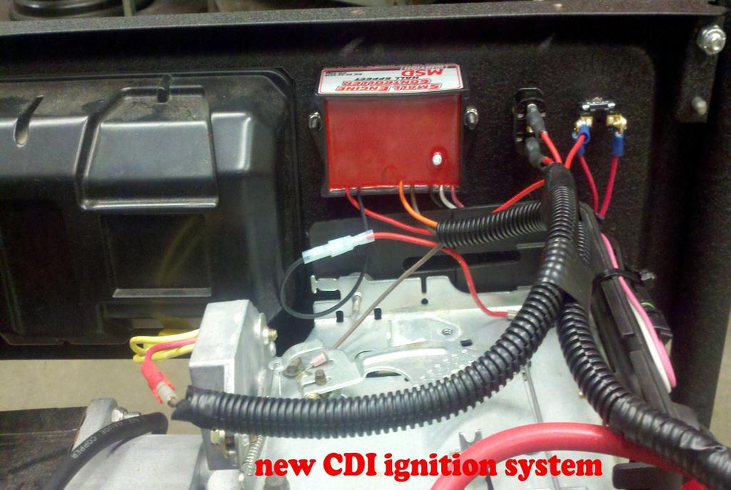
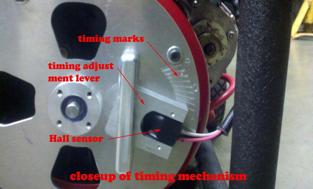
3 clip from the 2 gear shaft and remove. Remove the Hall sensor holder bracket. Pull the bracket and sensor holder out of the hole and install the Hall sensor from the MSD Kit on to the sensor holder (screws included). (Once you have the MSD wired to the engine and powered up, you can pass the magnet over the sensor and watch for the led to flash, the magnets north side with trip the sensor and the south side will not). Utilizing JB Weld Recommended, Epoxy the magnet that came with the MSD kit (north side of the magnet facing out from the 2 gear) and install the magnet in the hole provided on back side of the 2 gear. Before reinstalling the 2 gear, make sure the pin installed on the end of the 1 gear is in a vertical position. With the magnet facing the plate (away from engine) reinstall the 2 gear with the small hole on the backside of the gear in a horizontally position to the outside, so it lines up horizontally with the two gear shafts. Make sure the gear shafts and the hole in the 2 gear are lined up horizontally. Now reinstall the bracket and sensor holder, brass shim and retainer clip. Set the timing on the MFTCK- 100 to 0 and tighten the set screw on the end of the sensor holder to lock the gear shaft in place. 16. Before removing the shroud from the engine. Level out the MFTCK-100 so that it is at equal distance from the shroud all the way around, then measure the distance from the front of the flywheel shroud to the back of the MFTCK-100 plate, this is the length that the standoffs (included) need to be cut to. Remove the flywheel shroud from engine and install the MFTCK-100 utilizing the new holes you drilled into the fly wheel shroud and or the MFTCK-100 plate, depending on the engine you are installing the MFTCK-100 on. Insert the screws (included) thru the holes in the MFTCK-100, install standoffs on screws and bolt the MFTCK-100 to the existing or new holes (depending on you engine) in the shroud. Reinstall the flywheel shroud securely on to the engine. Make sure the center shaft and pin fits properly into the slot you have cut into end of the crank shaft. 17. ADJUSTING THE TIMING Rotating the Hall sensor clockwise RETARDS the timing, rotating the Hall sensor counter-clockwise ADVANCES the timing. If you set the engine at TDC = 0 mark on the timing marks on the timing plate, you get about 35 deg. advance and 35 deg. Retarded. So if you wanted the timing to be at 45 deg. ATDC, you would need to set the engine at TDC and set the timing on the MFTCK-100 to 10 deg. when first installed. At this point you can verify your timing with a timing light by shining the timing light thru the MFTCK-100 to view the white line that you painted on the flywheel earlier in step 6.. If you installed everything properly, the timing marks on the flywheel and MFTCK-100 will coincide, the white line should be in the vertical position and the timing on the
4 MFTCK-100 should be at 0 deg.. If the white timing line painted earlier on the flywheel does not coincide with the timing marks on the MFTCK-100 you will need to re adjust the gears on the back of the MFTCK-100 as was done in (step 14) to match the 0 deg. timing marks on both the flywheel and the MFTCK-100 timing marks. For fine adjustments un tighten the set screw on the 1 gear and rotate the 1 gear to the desired position and re tighten the set screw on the 1 gear. Recheck with a timing light. This will allow you to make fine adjustments in the timing as needed to obtain a true 0 degrees. 18. Congratulations, you just install our Multi-Fuel Timing Conversion Kit (MFTCK-100) kit on your engine and are now ready to run a verity of fuels in your new system. This Multi-Fuel Timing Conversion Kit will allow you the ability to run your engine without any worry of back flashes from the waste spark that these types of engines normally are out fitted with. You will also be able to advance or retard your timing to suit the fuel you are using. Please, always be careful in all your endeavors with your Multi-Fuel Timing Conversion Kit. Thank you for purchasing our Multi-Fuel Timing Conversion Kit.

5
6
7

8

9
10 Warranty: The Multi-Fuel Conversion KIT is sold for experimental and educational purposes. We warranty the Multi-Fuel Conversion Kit materials and our workmanship for 90 days from the delivery date of the Multi-Fuel Conversion Kit to the customer. The warranty does not cover misuse of the Multi-Fuel Conversion KIT and does not cover abuse or damage to the Multi- Fuel Conversion Kit due to incorrect installation and/or operation. This warranty does not apply to any damage that you may cause to your engine or yourself while installing the Multi-Fuel Conversion KIT. The warranty does not apply to any injury or damage that you may cause to yourself or to others or to your engine while installing and while using the Multi-Fuel Conversion KIT. Personal safety: By purchasing and accepting delivery of the Multi-Fuel Conversion KIT you thereby agree the ownership and all of the risks related to ownership passes to you. Be aware that by attempting to install the Multi-Fuel Conversion KIT you thereby agree to accept any and all direct and indirect risks, liabilities and responsibilities for its safe installation and operation. Please follow all shop safety practices for your own safety and the safety of all those around you.
PORSCHE V TO 32V CAM GEAR CONVERSION INSTRUCTIONS. For all 16V engines: USA 78-84, Euro
 PORSCHE 928 16V TO 32V CAM GEAR CONVERSION INSTRUCTIONS For all 16V engines: USA 78-84, Euro 77-86 2.0 cams@mrtubby.net Required parts not included in kit (2) HTD 32V cam gears - sprocket 928.105.530.01
2002 Escape Workshop Manual
 SECTION 303-01B: Engine 3.0L (4V) IN-VEHICLE REPAIR Procedure revision date: 10/09/2003 Timing Drive Components Removal CAUTION: Failure to verify correct timing drive component alignment will result in
Use Installation Procedure 1 when the crankshaft has NOT been rotated from the original position.
 2001 Blazer 4WD Applies to: 4.3L Report a problem with this article Removal Procedure Notice: There are two procedures available to install the distributor. Use Installation Procedure 1 when the crankshaft
PORSCHE V r Valve Timing Instructions. Copyright 2009 Written by Mike Frye Edited my Adam G.
 PORSCHE 928 32V r Valve Timing Instructions Copyright 2009 Written by Mike Frye Edited my Adam G. Sections: Overview.3 Disclaimer/warnings/things to watch for 4 Terms and naming conventions used in this
Distributor Replacement
 Page 1 of 11 2002 Chevrolet Chevy K Silverado - 4WD Sierra, Silverado (VIN C/K) Service Manual Document ID: 690165 Distributor Replacement Removal Procedure Notice: There are two procedures available to
DrVanos.com Stage II Installation Instructions. Tool rental is available with the purchase of a vanos kit *See website for more info*
 DrVanos.com Stage II Installation Instructions Special Tools Needed: Camshaft locking tool TDC Crank pin Sprocket turning tool Tool rental is available with the purchase of a vanos kit *See website for
Distributor: Service and Repair Distributor Replacement REMOVAL PROCEDURE
 2001 Chevy Truck S10/T10 Blazer 2WD V6-4.3L VIN W Copyright 2007, ALLDATA 9.50 Page 1 Distributor: Service and Repair Distributor Replacement REMOVAL PROCEDURE NOTE: There are two procedures available
2004 Chevy Truck Silverado WD V6-4.3L VIN X
 1 of 14 10/17/2013 8:32 PM 2004 Chevy Truck Silverado 1500 2WD V6-4.3L VIN X Vehicle» Powertrain Management» Ignition System» Distributor» Service and Repair» Distributor Replacement DISTRIBUTOR REPLACEMENT
Magnet Installation on Four Cylinder Lycoming Engines. 8 7/16 inch ID Flywheels Only. Sept. 21/18
 Magnet Installation on Four Cylinder Lycoming Engines. 8 7/16 inch ID Flywheels Only. Sept. 21/18 1. Locate the stamped TC#1 mark on the BACK of the flywheel as shown below 2. Now viewing the flywheel
CAUTION: READ INSTRUCTIONS CAREFULLY BEFORE STARTING INSTALLATION
 V-Twin MFG. VT No. 32-9500 V-TECH 1 IGNITION KIT, SINGLE FIRE FITS EV SHOVEL, XL THRU 1997 VT No. 32-9503 V-TECH 1 IGNITION KIT, SINGLE FIRE FITS EV, SHOVEL, XL, WITH COIL AND WIRES This is a custom application
Distributor Replacement (5.7L)
") Page 1 of 13 1999 Chevrolet Chevy K Pickup - 4WD Escalade, Pickup (Classic), Suburban, Tahoe, Yukon (VIN C/K) Service Manual Engine Engine Mechanical - 5.0L and 5.7L Repair Instructions Document ID: 371340
Page 1 of 13 1999 Chevrolet Chevy K Pickup - 4WD Escalade, Pickup (Classic), Suburban, Tahoe, Yukon (VIN C/K) Service Manual Engine Engine Mechanical - 5.0L and 5.7L Repair Instructions Document ID: 371340
DISTRIBUTORLESS IGNITION SYSTEM Installation and Adjustment Instructions
 DISTRIBUTORLESS IGNITION SYSTEM Installation and Adjustment Instructions 1.0 INTRODUCTION: Congratulations on your purchase of a Holley Distributorless Ignition System! Holley cannot and will not be responsible
Precision Degree Wheel Kit
 555-81621 Precision Degree Wheel Kit Instruction Booklet Instructions for 81621 Camshaft Degree Kit Thank you for purchasing the Jegs Camshaft Degree Kit. Please follow these detailed instructions to properly
Multi-tool 2CV / Visa
 Multi-tool 2CV / Visa For the professional 2CV specialist / perfectionist: The heart of the engine, the crankshaft and camshaft often needs a (partial) revision. There are many new 2CV parts, but for these
 Special Tools Needed: DrVanos.com Stage I Installation Instructions Camshaft locking tool TDC Crank pin Sprocket turning tool Tool rental is available with the purchase of a vanos kit *See website for
SDS Continental O-200 Installation Manual Aug. 4/17
 SDS Continental O-200 Installation Manual Aug. 4/17 This manual covers the steps to install the SDS EM-5 fuel injection and ignition system components on O-200 engines. Hall Sensor and Bracket Install
ACCEL Distributor Model #A557
 FORM 1627 REV1 INSTALLATION INSTRUCTIONS ACCEL Distributor Model #A557 CAUTION: CAREFULLY READ INSTRUCTIONS BEFORE PROCEEDING. NOT LEGAL FOR USE OR SALE ON POLLUTION CONTROLLED VECHICLES OVERVIEW ACCEL
Camshaft Degree Kit for Ford 5.0L 4V Coyote #4943
 INSTRUCTIONS Camshaft Degree Kit for Ford 5.0L 4V Coyote #4943 Thank you for choosing products; we are proud to be your manufacturer of choice. Please read this instruction sheet carefully before beginning
general booster conversion kit instructions
 general booster conversion kit instructions your kit may look slightly different than above instructions are general and work for many builds Unboxing your kit: 1. Remove new booster, bracket assembly
 Solid State Ignition Replacement May 15, 2005 Introduction: There are two Tecumseh Solid State Ignitions ( SSI ) configurations we are concerned with here: The one on the left I call SSI Under for short
1. Disconnect negative battery cable. 2. Remove upper and lower front timing belt covers..
 BELT AND SPROCKETS-TIMING REMOVAL TIMING BELT Zoom 1. Disconnect negative battery cable. 2. Remove upper and lower front timing belt covers.. CAUTION: When aligning crankshaft and camshaft timing marks
INSTALLATION INSTRUCTIONS for HI-1 and HI-2 MOTORCYCLE IGNITIONS. Part Numbers and INTRODUCTION COIL AND SPARK PLUG CABLE CONSIDERATIONS
 INSTALLATION INSTRUCTIONS for HI- and HI- MOTORCYCLE S Part Numbers 8-000 and 8-000 CAUTION: READ INSTRUCTIONS CAREFULLY BEFORE STARTING INSTALLATION INTRODUCTION Crane HI- and HI- ignition systems are
Timing Belt Replacement
 2004 Accord Timing Belt Replacement Report a problem with this article NOTE: The following procedure is for the installation of a new timing belt. If you are installing a used belt, refer to the timing
Timer. TipTop Timers. Installation and Operation Manual
 TipTop s E TM Installation and Operation Manual Sold by: TipTop s LLC 2225 North Dollar Road Spokane Valley, WA 99212 web: Model T Electronic - E E Conversion Kit Contents The Electronic conversion kit
420cc Builder Modified Predator OHV engine Technical Specifications 5/27/13
 BM (Builder Modified) Predator 420cc OHV engine With Electric Start Approved Engine: OHV Predator 420cc engine modified only according to these BM OHV Engine Spec. ENGINE SPEC SHEET FOR BM 420cc OHV CLASS
SDS Continental IO-550 Installation Manual
 SDS Continental IO-550 Installation Manual July14/18 This manual covers the steps to install the SDS EM-5 fuel injection and ignition system components on IO-550 engines. Checking Clearance for Hall Sensor
CAUTION. Fuel Injection Pump, In-Line, Spill Port Timing
 Page 4 of 22 Rotate the crankshaft counterclockwise, as viewed from the front of the engine, to approximately 40 degrees before TDC. Both the RQV and RQV-K governor require the shutdown lever to be in
Models Affected: Visions with Propane Engines CORRECTIVE ACTION ---- PROCEDURE
 Propane Belt Squeal Models Affected: Visions with Propane Engines ISSUE Front End Accessory Drive (FEAD) Belt chirping/squealing caused by improper fore-aft crankshaft pulley positioning. CORRECTIVE ACTION
Tri-Spark - Classic Triple Trident & R3 Installation Instructions
 Tri-Spark - Classic Triple Trident & R3 Installation Instructions TRI-0002 Copyright Tri-Spark 2015 Revised June 2015 Thank you for purchasing the Tri-Spark Classic Triple Ignition system. For your own
460cc Do-It-Yourself Assembly Guide
 2995 Coleman St North Las Vegas, NV 89032 702-530-7753 702-643-7517 FAX VegasCarts.com 460cc Do-It-Yourself Assembly Guide *DIY Engines do not come with a warranty, these kits are intended for experienced
Distributor Replacement (HVS)
") 1 of 8 3/3/2018, 3:02 PM 1998 Chevrolet K Pickup - 4WD Chevy Pickup, GMC Pickup, Suburban, Tahoe, Yukon VIN C/K Service Manual Engine Engine Electrical Repair Instructions Document ID: 207477 Distributor
1 of 8 3/3/2018, 3:02 PM 1998 Chevrolet K Pickup - 4WD Chevy Pickup, GMC Pickup, Suburban, Tahoe, Yukon VIN C/K Service Manual Engine Engine Electrical Repair Instructions Document ID: 207477 Distributor
Installing the PAMCO CB750, CB550, CB500 Four, CB400F and CB350F Ignitions
 Installing the PAMCO CB750, CB550, CB500 Four, CB400F and CB350F Ignitions Section A Removing the Existing Points Plate a1. Remove the points plate and advance mechanism. Follow the instructions in your
Service and Repair Note:
 Service and Repair Note: Ford does not provide camshaft gear timing marks, or information to perform timing belt service without the special tools shown in this procedure. Timing Drive Components - Timing
World Formula TECH MANUAL
 World Formula TECH MANUAL Section 1 General Rules 1. Only stock Briggs & Stratton World Formula Model # 124435-8101 will be used in this class except as provided in this Tech manual. All parts will be
12/30/2018 Fuel/Ignition Ignition Distributor Removal and Installation Distributors 1997 Dodge RAM Pickup (5.2L V8) - BR MotoLogic
 - BR MotoLogic") 1997 RAM Pickup (5.2L V8) - BR DISTRIBUTORS REMOVAL Report a problem with this article CAUTION: Base ignition timing is not adjustable on any engine. Distributors do not have built in centrifugal or vacuum
1997 RAM Pickup (5.2L V8) - BR DISTRIBUTORS REMOVAL Report a problem with this article CAUTION: Base ignition timing is not adjustable on any engine. Distributors do not have built in centrifugal or vacuum
2018 Junior Sprint Rules
 2018 KidSprint Engine Rules Briggs World Formula 2018B All parts must be Briggs & Stratton factory production parts unless otherwise noted in these rules. No machining, polishing or alteration of any parts
Installation Guide for the Electronic Ignition Distributor
 Installation Guide for the Electronic Ignition Distributor Remanufactured By East Coast Roadster East Coast Roadster: Ignition systems and accessories for Datsun Roadster fanatics! PLEASE, Call with any
NUMBER: S.M. REF.: Listed in Table ENGINE: DD15 DATE: February 2009
 NUMBER: 2 10-09 S.M. REF.: Listed in Table ENGINE: DD15 DATE: February 2009 SUBJECT: CAMSHAFT TIMING ADDITIONS, REVISIONS, OR UPDATES Publication Number Platform Section Title Change Page Number(s) DDC-SVC-MAN-0002
Magnet Installation on Six Cylinder Lycoming Engines. 8 7/16 inch ID Flywheels Only. Aug. 9/16
 Magnet Installation on Six Cylinder Lycoming Engines. 8 7/16 inch ID Flywheels Only. Aug. 9/16 Your flywheel should have 12 holes spaced 30 degrees apart as shown in the photo below. These holes will be
Calibration Procedures:
 Calibration Procedures: Setting the Ignition Timing Correction Selecting an Advance Curve Setting Rev Limit RPM These Instructions are for Tempest II Ignitions Only Rev. C // Severe engine damage is possible
Timing Belt: Service and Repair 2002 Acura Truck MDX V6-3.5L
 Timing Belt: Service and Repair 2002 Acura Truck MDX V6-3.5L Timing Belt Removal Special Tools Required - Holder handle 07JAB-001020A - Holder attachment, 50 mm, offset 07MAB-PY3010A - Socket, 19 mm 07JAA-001020A
CAUTION: CAREFULLY READ INSTRUCTIONS BEFORE PROCEEDING.
 Twin Tec Installation Instructions for Ignition CAUTION: CAREFULLY READ INSTRUCTIONS BEFORE PROCEEDING. OVERVIEW Twin Tec ignition is states street legal (ARB E.O. No. D--) for use with the following Harley-Davidson
Timing Chain: Service and Repair With 2 Piece Tensioner (TSB A) Precaution. Removal This article has been updated with bulletin No A.
 Precaution. Removal This article has been updated with bulletin No A.") 1997 Chevrolet Cavalier L4-144 2.4L DOHC VIN T SFI Page 1 Timing Chain: Service and Repair With 2 Piece Tensioner (TSB 67-61-22A) Precaution Bulletin No.: 67-61-22A Date: July, 1998 TIMING CHAIN TENSIONER
1997 Chevrolet Cavalier L4-144 2.4L DOHC VIN T SFI Page 1 Timing Chain: Service and Repair With 2 Piece Tensioner (TSB 67-61-22A) Precaution Bulletin No.: 67-61-22A Date: July, 1998 TIMING CHAIN TENSIONER
INSTALLATION INSTRUCTIONS for HI-4 DUAL FIRE MOTORCYCLE IGNITION. Part Number INTRODUCTION REMOVAL OF POINTS IGNITION TO 1977 MODELS
 INSTALLATION INSTRUCTIONS for HI- DUAL FIRE MOTORCYCLE IGNITION Part Number -00 CAUTION: READ INSTRUCTIONS CAREFULLY BEFORE STARTING INSTALLATION INTRODUCTION The HI- ignition system is intended for use
Pontoon Assembly Instructions and manual. Read before using hoist.
 Page 1 Pontoon Assembly Instructions and manual. Read before using hoist. For Models 32BL18, 32BL22, 32BL25 and 42BL28 R Model 32BL22 Shown Proudly Made in Michigan By NuCraft Metal Products 402 Southline
Local Option 206 Rules Manual Section 1 General Rules 1. Only stock Briggs & Stratton LO206 # engine will be allowed in this class.
 Local Option 206 Rules Manual Section 1 General Rules 1. Only stock Briggs & Stratton LO206 # 124332-8201engine will be allowed in this class. o All parts will be stock unaltered Briggs & Stratton Animal
Classification: Reference: Date: VE30DE CAM TIMING
 Classification: Reference: Date: EM93-002 NTB93-126 September 2, 1993 VE30DE CAM TIMING APPLIED VEHICLE(S): All equipped with VE30DE Engine SERVICE INFORMATION When servicing VE30DE engine cylinder heads,
Ford V8 Distributor Installation Instructions with Mechanical Advance
 Ford V8 Distributor Installation Instructions with Mechanical Advance These instructions will help you to install a Ford V8 distributor with Mechanical Advance style distributor. Please read these instructions
Briggs & Stratton Animal TECH MANUAL Version 1.6 Section 1 General Rules cannot Section 2 Required Modifications Section 3 Allowable Modifications
 Briggs & Stratton Animal TECH MANUAL Version 1.6 updated 2/ 7 / 2011 Section 1 General Rules 1. Only stock Briggs & Stratton Animal # 124332-8201and 124332-8203 - 01engine will be allowed in this class.
The spacers can be made out of.750 round aluminum bar with a.3125 to.318 hole drilled in center.
 SECTION I : FRONT COVER INSTALLATION With Crankshaft, Camshaft and oil Galley plugs installed in engine, you need to verify that the front cover clears the oil galley plugs and fits on engine block. The
INSTALLATION INSTRUCTIONS
 INSTALLATION INSTRUCTIONS www.factorydirectperf.com Made exclusively for FDP by SEA-DOO 800 Enhancer Ignition, PN 30-08-2630 Fits SEA-DOO XP, GSX, GTX Watercraft w/rave Engine IMPORTANT: Read these instructions
Kid Sprint Engine Rules Briggs World Formula
 Kid Sprint Engine Rules Briggs World Formula 2017 Jr Sprint Engine Rules Briggs World Formula effective 2/1/2017. All parts must bebriggs & Stratton factory production parts unless otherwise noted in these
Installing the PAMCO Suzuki GS750 GS850 GS1000 Ignition
 Installing the PAMCO Suzuki GS750 GS850 GS1000 Ignition Section A Removing the Existing Points Plate 1. Remove the points plate and advance mechanism. 2. Remove the points cam from the advance mechanism.
Poor Idle Quality AJ16 Engine Valv. alve Timing Modification. Engine numbers listed below
 TECHNICAL BULLETIN Poor Idle Quality Normally Aspirated AJ16 Engine Valv alve Timing Modification MODEL 4.0L Normally Aspirated 1995 MY Engine numbers listed below DATE 8/95 12-57 ISSUE: To improve idle
ENGINE REMOVAL Install: Exhaust pipe 1 5. Tighten: Nuts (exhaust pipe) 2. Exhaust pipe nut 20 Nm (2.0 m kgf, 14 ft lbf) 6.
 2. Exhaust pipe nut 20 Nm (2.0 m kgf, 14 ft lbf) 6.") ENGINE REMOVAL 4. Install: Gasket New Exhaust pipe 1 5. Tighten: Nuts (exhaust pipe) 2 Exhaust pipe nut 20 Nm (2.0 m kgf, 14 ft lbf) 6. Install: Clamp Slide the clamp onto the end of the muffler and insert
ENGINE REMOVAL 4. Install: Gasket New Exhaust pipe 1 5. Tighten: Nuts (exhaust pipe) 2 Exhaust pipe nut 20 Nm (2.0 m kgf, 14 ft lbf) 6. Install: Clamp Slide the clamp onto the end of the muffler and insert
How To Verify Your Valve/Crankshaft Timing & Set A Distributor.
 How To Verify Your Valve/Crankshaft Timing & Set A Distributor. If you don't have a good working knowledge of shop safety practices, DON'T ATTEMPT THIS! If you don't possess common sense or self preservation
INSTALLATION INSTRUCTIONS
 INSTALLATION INSTRUCTIONS REAR CONVERSION KIT A111-2 (FORD 8" & 9" SMALL BEARING) & REAR CONVERSION KIT A111-3 (FORD 9 TORINO) Thank you for choosing STAINLESS STEEL BRAKES CORPORATION for your braking
FORD FAIRLANE Booster Conversion Kit ( TORINO, RANCHERO )
") 1966-1971 FORD FAIRLANE Booster Conversion Kit ( TORINO, RANCHERO ) F R Unboxing your kit: 1. Remove new booster, bracket assembly and master cylinder from their boxes and inspect the parts. 2. New boosters
1966-1971 FORD FAIRLANE Booster Conversion Kit ( TORINO, RANCHERO ) F R Unboxing your kit: 1. Remove new booster, bracket assembly and master cylinder from their boxes and inspect the parts. 2. New boosters
HD 7700 Setup & Operator Manual
 HD 7700 Setup & Operator Manual Issue 1 December, 01 Performance Design Inc. The Heavy Duty Ultima (HD 7700) electric punch has been designed to punch most any job that may pass through your bindery or
SUM Chevy Truck frame mount booster kit
 SUM-760211 1955-1959 Chevy Truck frame mount booster kit Unboxing your kit: 1. Remove new booster, bracket assembly and master cylinder from their boxes and inspect the parts. 2. New boosters come with
Remove the 3-11mm nuts holding mirror on. Don t drop the nuts!
 2005-2012 Ford Mustang Puddle Lamp Kit Parts List: Quantity: Tool List: LED Lamps 2 Flat head screwdriver Seals 2 Ratchet & Socket set OR Nuts 2 Adjustable Wrench Wiring harness 1 Drill & 11/16 th bit
2012 Honda Crosstour EX ENGINE Cylinder Head - (4-CYL)
") Fig. 4: Identifying Cylinder Head Components Location (3 Of 3) ENGINE COMPRESSION INSPECTION NOTE: After this inspection, you must reset the PCM. Otherwise, the PCM will continue to stop the fuel injectors
Fig. 4: Identifying Cylinder Head Components Location (3 Of 3) ENGINE COMPRESSION INSPECTION NOTE: After this inspection, you must reset the PCM. Otherwise, the PCM will continue to stop the fuel injectors
BULLETIN TESTING. Article from Honda Service News. DTC P0341: CMP Sensor A and CKP Sensor Incorrect Phase Detected. Troubleshooting Flowchart
 2005 Honda Truck CR-V 4WD L4-2.4L Vehicle > ALL Diagnostic Trouble Codes ( DTC ) > Testing and Inspection > P Code Charts > P0341 BULLETIN TESTING Article from Honda Service News DTC P0341: CMP Sensor
Universal Cam Sync Systems Holley PN
 Universal Cam Sync Systems Holley PN 556-123 NOTE: For a full color version of this instruction manual, please search for P/N 556-123 @ www.holley.com. 1.0 INTRODUCTION: A cam sync signal is required to
INTERCOOLER UPGRADE INSTALLATION INSTRUCTIONS PART NUMBER D
 INTERCOOLER UPGRADE INSTALLATION INSTRUCTIONS PART NUMBER D330-0021 APPLICATION: 2014-16 F22 228i & xdrive coupe (see restrictions below) 2015-16 F23 228i & xdrive convertible 2012-16 F30 328i & xdrive
2001 Escort Workshop Manual
 Page 1 of 6 SECTION 303-01B: Engine 2.0L Zetec 2001 Escort Workshop Manual IN-VEHICLE REPAIR Procedure revision date: 10/26/2004 Timing Drive Components Timing Belt Special Tool(s) Crankshaft TDC Timing
EM-5 F Aviation Ignition System Installation and Basic Tuning. Oct. 1/17
 EM-5 F Aviation Ignition System Installation and Basic Tuning. Oct. 1/17 Disclaimer These products do not conform to any recognized set of standards or certifications for aviation applications. This ECU
- BRONZE SERIES 30 - INSTALLATION MANUAL
 - BRONZE SERIES 30 - INSTALLATION MANUAL Thank you for purchasing our high quality retract system! We hope you will soon be experiencing the joy of flicking the retract switch with confidence and then
POLESTAR HS Management System
 POLESTAR HS Management System Installation Instructions This document contains the information needed to install and adjust the POLESTAR HS Engine Management System. It assumes that the system already
Tri-Spark Ignition System Installation Triple Cylinder TRI-0001
 Tri-Spark Ignition System Installation Triple Cylinder TRI-0001 There are potentially lethal high voltages produced at the ignition coils and spark plugs, therefore every precaution must be taken to prevent
INSTALLATION INSTRUCTIONS RATTLER STEEL RUNNING BOARDS FORD TRANSIT VAN (FULL SIZE)
") INSTALLATION INSTRUCTIONS PARTS LIST: 1 32-inch Steel Running Board 1 8-1.25mm x 35mm Hex Bolt 1 96-inch Steel Running Board 13 8-1.25mm x 25mm Hex Bolt 5 Passenger Side/Driver Side Mounting Brackets 20
INSTALLATION INSTRUCTIONS PARTS LIST: 1 32-inch Steel Running Board 1 8-1.25mm x 35mm Hex Bolt 1 96-inch Steel Running Board 13 8-1.25mm x 25mm Hex Bolt 5 Passenger Side/Driver Side Mounting Brackets 20
BMW N12 PSA 1.4 / 1.6 Chain. Engine timing tools. K 10558
 Engine timing tools BMW N12 PSA 1.4 / 1.6 Chain K 10558 www.kamasatools.com Plan Layout C A D A B Component Identification Ref OEM Ref BMW OEM Ref PSA Description A 11 9 540 0197-A3 B 11 9 540 0197-A1
INTERCOOLER UPGRADE INSTALLATION INSTRUCTIONS PART NUMBER D
 INTERCOOLER UPGRADE INSTALLATION INSTRUCTIONS PART NUMBER D330-0021 APPLICATION: 2014-16 F22 228i & xdrive coupe (see restrictions below) 2012-16 F30 328i & xdrive sedan 2014-16 F31 328i xdrive wagon 2014-16
Prerequisites: Shop Manual (recommended) pages 3-9 through 3-13.
 pages 3-9 through 3-13.") Prerequisites: Order your gaskets average about $25.00 bucks X 2 so $50.00 4NK-11193-00-00 Obtain a shim kit (Should have several 265 and 270s) (Some dealers will exchange) Obtain a Valve Bucket Tool YM-33961
Prerequisites: Order your gaskets average about $25.00 bucks X 2 so $50.00 4NK-11193-00-00 Obtain a shim kit (Should have several 265 and 270s) (Some dealers will exchange) Obtain a Valve Bucket Tool YM-33961
Ignition Installation Troubleshooting Tips/Frequently-Asked Questions
 Ignition Installation Troubleshooting Tips/Frequently-Asked Questions Warning: Reversing the red and black ignition wires will destroy the ignition module and void the warranty. The Hot-Spark module s
PRODUCT MANUAL Gecko Wireless 2 Zone LED Dimmer and Receiver
 Product Description The Gecko Wireless 2 Zone Wall LED Dimmer has been designed to bring light control easily. No wires or switch box locations are needed, just stick or mount the Gecko to any flat location
Briggs & Stratton! Animal. Tech Manual
 Briggs & Stratton Animal Tech Manual 1 st Edition April 15 th,2011 Updated: November 20, 2013 QMA National Technical Director: Rusty Barnard ANIMAL CLAIM RULE - For M SERIES QMA Type Engines 2012 Quarter
VALVE CLEARANCE (K3-VE)
") ENGINE MECHANICAL VALVE CLEARANCE (K3-VE) 25 ENGINE MECHANICAL VALVE CLEARANCE (K3-VE) INSPECTION 1. DISCONNECT NEGATIVE BATTERY TERMINAL (See page RS-164.) 2. ROVE ENGINE UNDER COVER 3. DRAIN ENGINE COOLANT
ENGINE MECHANICAL VALVE CLEARANCE (K3-VE) 25 ENGINE MECHANICAL VALVE CLEARANCE (K3-VE) INSPECTION 1. DISCONNECT NEGATIVE BATTERY TERMINAL (See page RS-164.) 2. ROVE ENGINE UNDER COVER 3. DRAIN ENGINE COOLANT
Maintaining the Teledyne Bendix D-3200 series Magneto
 Maintaining the Teledyne Bendix D-3200 series Magneto GENERAL: Good standard shop practices and safety precautions should be observed at all times to avoid injury to personnel and damage to equipment.
MAGNETO REPLACEMENT. Pre-Unit Twin Cylinder Motorcycles. ELECTRONIC IGNITION SYSTEM For 4 Stroke. With 12 VOLT Electrics, POS/ NEG Ground
 Sure ー Fire MAGNETO REPLACEMENT ELECTRONIC IGNITION SYSTEM For 4 Stroke Pre-Unit Twin Cylinder Motorcycles With 12 VOLT Electrics, POS/ NEG Ground SYSTEM TYPE: PAMT1 2 Sure-Fire System Contents: MAGNETO
Timing Belt: Service and Repair
 1996 Honda Accord Sedan L4-2.2L SOHC (16 Valve) Copyright 2009, ALLDATA 9.90 Page 1 Timing Belt: Service and Repair TIMING BELT AND TIMING BALANCER BELT REMOVAL Timing Components NOTE: - Turn the crankshaft
1995 Mitsubishi Montero LS. Ensure timing marks are aligned. Mark timing belt direction of rotation.
 TIMING BELT NOTE: Ensure timing marks are aligned. Mark timing belt direction of rotation. Removal 1. Disconnect negative battery cable. Drain engine coolant. Remove engine coolant reservoir tank, fan
Fiat X1/9 1500cc Engine Timing Belt Replacement, Cam Timing and Static Ignition Timing. Photos courtesy of Don Doan.
 Fiat X1/9 1500cc Engine Timing Belt Replacement, Cam Timing and Static Ignition Timing. Photos courtesy of Don Doan. Introduction This document outlines how to replace a timing belt on a Fiat X1/9 1500cc
Tachometers and Tach/Hourmeters
 Tachometers and Tach/Hourmeters AT and ATH Series Installation Instructions IMPORTANT! These instructions are specific to tachometer models with a power input operating range of 11-28 VDC and calibration
Starter One-Way Clutch Replacement
 Starter One-Way Clutch Replacement by Joe Conway YOU NEED THE RIGHT TOOLS TO DO THIS JOB!! IF YOU HAVE ANY HESITATIONS TAKE IT TO A SHOP. I CLAIM NO RESPONSIBILITY FOR DAMAGE DUE TO MISTAKES MADE DURING
Remove 4 circled pins. Route wiring along dashed line. Remove the 2 9mm nuts and black retaining plate that secure extractor.
 2015 Ford Mustang Turn Signal Hood Kit Parts List: Quantity: Tool List: Bracket & pre-installed lamp 2 Flat head screwdriver Wiring harness 1 Phillips screwdriver PB-3660 Parts Bag 1 Ratchet & Socket set
Engine Cylinder Head Installation
 Engine Cylinder Head Installation Important: Install the cylinder head without the camshafts. 1. Install the engine cylinder head to the engine block. 2. Install the AIR pump bolt and fir tree fastener
PRODUCT MANUAL Gecko Wireless One Zone LED Dimmer and Receiver
 Product Description The Gecko Wireless One Zone Wall LED Dimmer has been designed to bring light control easily. No wires or switch box locations are needed, just stick or mount the Gecko to any flat location
4. Remove distributor hold-down. Lift the distributor upwards and remove.
 Holley Sniper EFI HyperSpark Distributors are designed to plug and play with Sniper EFI systems. This design includes a single Hall Effect sensor providing crankshaft speed to the ECU. The precision machined
Valve Clearance Adjustment
 2006 Odyssey Valve Clearance Adjustment Report a problem with this article NOTE: Adjust the valves only when the cylinder head temperature is less than 100 ºF (38 ºC). 1. Remove the intake manifold. 2.
KIT TOOLS MANUAL For Engine Assembly
 KIT TOOLS MANUAL For Engine Assembly Preface This manual provides motorcycle teams with clear information on a line of tools that simplify basic tuning. We believe that these tools make engine tuning accessible
DISASSEMBLY. SORENTO(BL) > 2004 > G 3.5 DOHC > Engine Mechanical System
 > 2004 > G 3.5 DOHC > Engine Mechanical System") SORENTO(BL) > 2004 > G 3.5 DOHC > Engine Mechanical System DISASSEMBLY 1. Remove the engine cover. 2. Disconnect the battery negative terminal. 3. Disconnect the radiator lower hose. 4. Disconnect the
SORENTO(BL) > 2004 > G 3.5 DOHC > Engine Mechanical System DISASSEMBLY 1. Remove the engine cover. 2. Disconnect the battery negative terminal. 3. Disconnect the radiator lower hose. 4. Disconnect the
INSTRUCTIONS FOR INSTALLATION OF THE CH-2 and CH-3 DRIVE UNIT TO AN ENGINE WARNING
 INSTRUCTIONS FOR INSTALLATION OF THE CH-2 and CH-3 DRIVE UNIT TO AN ENGINE WARNING! Never reach hands or other body parts in or near moving parts!! Maintain a safe distance from any fixed or moving propeller!!
INSTALLATION INSTRUCTIONS
 INSTALLATION INSTRUCTIONS PERFORMANCE AT THE WHEELS KIT W155-5 CHRYSLER 8 3 /4" & 9 3 /4" REAR AXLES Thank you for choosing STAINLESS STEEL BRAKES CORPORATION for your braking needs. Please take the time
Cam Timing Tool 850 all, S/V/C only ipd #
 PI-401 04/11 Dedicated to improving vehicle fun, safety & performance Installation Instructions PI401 Cam Timing Tool 850 all, S/V/C70 1998 only ipd #25.0039 SUGGESTED TOOLS 10mm, 12mm, 30mm sockets rachet
RTI TECHNOLOGIES, INC.
 Hub Arm Assembly RTI TECHNOLOGIES, INC. York, PA 17402 800-468-2321 (ext. 259) Manual P/N 035-80608-00 Table of Contents 1 Introduction... 1 2 Safety... 2 3 Material List... 3 4 Mounting of Hub & Centering
Retrofit Steering Column
 Retrofit Steering Column INSTALLATION INSTRUCTIONS for 1965 Ford Falcon FOR PART NUMBER S: 1170906010, 1170906020, 1170906051, 1130906010, 1130906020, 1130906051 S INCE 1986 www.ididitinc.com 610 S. Maumee
1992 Mitsubishi 3000GT VR-4
 TIMING BELT Removal (Diamante SOHC) 1. Remove left front and left side splash shields. Using engine hoist, lift engine just enough to remove weight from engine mounts. Remove drive belts. Remove A/C tensioner
Service Bulletin Cylinder Head Service. September 17, 2002
 Service Bulletin 02-047 Applies To: 1998 02 Passport ALL September 17, 2002 Cylinder Head Service BACKGROUND In the 1998 through 2002 Passport Service Manuals, some of the information on cylinder head
TIMING BELT AND SPROCKET(S) REMOVAL - TIMING BELT
 REMOVAL - TIMING BELT") TIMING BELT AND SPROCKET(S) REMOVAL - TIMING BELT 1. Disconnect negative battery cable. 2. Raise vehicle on hoist. Remove right front wheel. 3. Remove belt splash shield. 4. Remove accessory drive belts.
TIMING BELT AND SPROCKET(S) REMOVAL - TIMING BELT 1. Disconnect negative battery cable. 2. Raise vehicle on hoist. Remove right front wheel. 3. Remove belt splash shield. 4. Remove accessory drive belts.