Gen4 EFI. Installation Instructions. CB Performance s. Step 1 - Pre Installation Procedures
|
|
|
- Elijah Parker
- 6 years ago
- Views:
Transcription
 CB Performance s Gen4 EFI Installation Instructions Step 1 - Pre Installation Procedures A) Before beginning this installation, read the instructions completely and be certain you")

1 Version 0.2 (6/16/15) CB Performance s Gen4 EFI Installation Instructions Step 1 - Pre Installation Procedures A) Before beginning this installation, read the instructions completely and be certain you understand all aspects of the installation before proceeding. There will also be some necessary tests to perform on the vehicle to ensure a successful install. Check voltage output of the alternator to make sure it falls within acceptable tolerances. This will be between volts. Check the battery to make sure it is fully charged and is in good condition. The standard Bosch "Blue Coil" is NOT compatible with this system. Standard VW solid core plug wires must NOT be used. A high quality suppression core wire is required. RESISTOR SPARK PLUGS ARE REQUIRED! Ask the tech representative at CB Performance for recommendations. B) Disconnect the battery. DO NOT proceed further without doing so. It is advisable after disconnecting the battery to drain the fuel tank and remove it. Disconnect the fuel line at the engine and blow the line clear with compressed air (wear eye protection) to be absolutely certain the fuel line is clear of any foreign material or debris. It is recommended to install two 3/8 fuel lines from the fuel tank to the engine. The larger 3/8" line is needed to prevent fuel starvation to the engine on larger/higher horsepower engines. Make sure the supplied fuel filter is installed. The 1/2" filter is the pre-filter and is installed between the tank outlet and the fuel pump. This is a very high-pressure system. Make sure all hose connections are tight and leak proof. Remove the existing carburetors and fuel pump. It may be necessary to mock up the 48 mm throttle bodies and linkage to make sure it fits your particular configuration. Once satisfied with the fit, remove them and use tape to cover the intake ports to prevent any debris from entering the engine N. Farmersville Blvd. Farmersville, CA Toll Free:


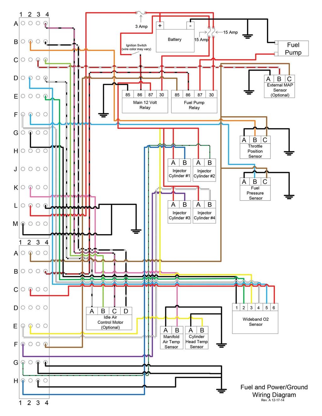
2 cbperformance.com Step 2 - Wiring Stretch out the wiring harness to determine the best routing of the wiring for your particular application based on where you want to mount the EMS. If the EMS is going to be installed in a Beetle/Karmann Ghia, the EMS is supposed to be installed under the back seat opposite the battery. In off road applications or open cockpit vehicles where the environment is a factor, find the best possible mounting point (an enclosure is a must). Ensure that the harness will reach the engine correctly from it's mounting point. The harness is clearly tagged for where all the wires need to go. The ends which connect to the injectors, throttle position sensor, cylinder head temp sensor, O2 sensor, ignition wiring and the ganged ground wires (engine case attachment required) will need to be routed into the engine bay. A minimum 1 1/4" hole will need to be drilled wherever the wiring is to pass thru sheet metal, so plan well. This is the easiest to do when the throttle bodies/carbs are off for best access. DO NOT cut or modify the wire harness. The harness is designed for your application and modifying it will VOID any type of warranty or support from CB Performance. NOTE: The fuel pump must be mounted in the horizontal position. Mounting the fuel pump vertically will damage it. Do not mount the pump at the rear of the vehicle. The fuel pump is designed to be gravity fed from the tank. Trying to pull the fuel through the small diameter stock fuel line will compromise the efficiency of the pump and cause it to run hot or cause it to fail. A pump can tolerate restrictions on the discharge much better than on the suction side. Mount the EMS under the back seat opposite the battery side of the tunnel. Keeping the EMS connector where the EMS is mounted, pull the engine bay segment of the wiring through the hole(s) you drilled being careful not to cut the insulation sheathing as you pass it through. Be sure there is enough slack in the wiring to attach all the connectors without stretching the wires too tightly. Step 3 - Hardware Installation Under no circumstances should Teflon tape be used on any threads in this kit. Use only Blue Loctite for threaded sealant. Teflon tape will find its way into the fuel injectors and or the fuel pump and damage them. The cylinder head temp sensor is to be installed in the 3-4 cylinder head area. If using bolt on valve covers, we recommend that it be installed in the valve cover bail boss. If using clip on style valve A B


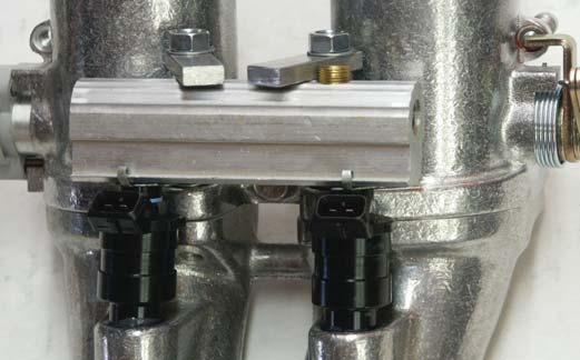
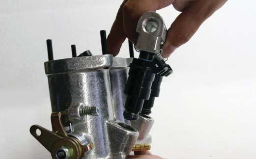
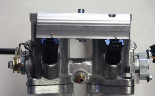
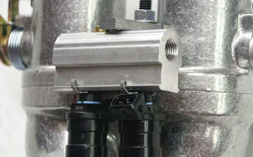
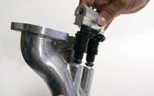
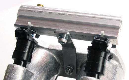
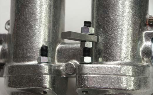
3 cbperformance.com C E E covers, we recommend that it be installed below the boss. Make sure before you drill a hole into your cylinder head that there is no interference from push rods or head studs and the sensor. Use an 11/32" drill and an 1/8" NPT pipe tap. You will break through into the rocker box of the head, so be prepared to catch the shavings to prevent entry into the engine. Clean the shavings from the tapped hole and install the sensor using blue loctite for thread sealant. There are several types of throttle body/manifold setups. Regardless of the setup you are running you must first push the injector clips onto the injectors. Then grease up the "O" rings on the injectors (DO NOT USE OIL). Take the injectors and push them up into the fuel rails until they seat all the way and you hear the clip latch onto the rail. Take note D that none of the o-rings have been pinched. Next take the rail assembly and push it down into either the throttle body or manifold. In either throttle body or manifold assembly, some fuel rail hold downs need to be used. Refer to pictures to correctly assemble the hold down assemblies. Depending on your vehicle configuration, it may be easier to install the manifolds first without the throttle body rather than the whole assembly. Remove the tape covering the intake ports and install the throttle bodies with the supplied gaskets. On all applications, make sure you have a good chassis ground, free of rust or powder coating. Install the Fuel Regulator (FPR) between the last remaining port of the two fuel rails and the fuel 'T' under the tank. The FPR must NOT be mounted inside the engine compartment. Extended periods of high temperatures will cause fluctuations F
4 cbperformance.com G K H L I M J N


5 cbperformance.com in your fuel pressure. Make sure the vacuum line is securely attached to the vacuum port of the FPR. After engine is started, the FPR needs to be set to 45 idle. Re-check the pressure after the engine warms up. If the pressure has changed you will need to re-adjust it to 45 idle. For those with IAC motors, skip the next part. Connect a 1/4" vacuum hose to the barbed fitting in each throttle body. You will need to install a vacuum T in this line. The T will go to the fuel pressure regulator. In this line, you will add another T to run vacuum to the MAP sensor located at the ECU. Take a small nylon zip tie, and use it as a clamp to secure the line to the fuel pressure regulator. It will be necessary to weld an O2 sensor bung into the exhaust if one is not already present. o p If a 4 into 1 header is being used, install the bung into the muffler head pipe a few inches away from the collector flange, preferably at somewhere between the 10 O Clock and 2 O Clock position. Turbo Applications: Weld the O2 sensor bung after the turbo. Please refer to the pictures to see the recommended placement of the O2 sensor. Insure O2 Sensor clears turbo drain pipe. Step 4 - Linkage The first step to assemble your linkage is to slide the linkage arms onto the hex bar. The two linkage arms mount on each end of the hex bar while the straight throttle cable arm mounts in the middle. The throttle cable arm locates 60 degrees, or "one hex degree" down from the linkage arms. There are two centering springs supplied in your kit. Grease these springs very well and push them into each end of the hex bar. Take the two threaded swivel balls and jam nuts and thread them into the linkage bases that are mounted on your throttle bodies. Slip one end of the hex bar into the swivel ball. While centering the other end, slide it into the second swivel ball. It might be necessary to loosen the throttle body or intake manifold to make enough room to slide the hex bar into place. The swivel balls will need to be adjusted outward until there is a 1/4" of side to side movement of the hex bar. Try to keep the outward adjustment of the swivel balls the same from side to side. Once this is accomplished, lock the jam nuts down. Make sure you have at least a 1/4" of hex bar free play after tightening the jam nuts. The linkage rods and heim joints are next. There are four heim joints in all. Two right hand and two

6 cbperformance.com left hand heim joints with corresponding lock nuts. Each side will need one of each. The linkage rods are equipped with matching right and left hand threads. Thread the locknuts and heim joints onto the linkage rods. Leave these loose for now. After the assembly of the linkage rods is done, secure them to the cross bar linkage arms and the throttle body linkage arms. You will need two open ended wrenches for this operation, an 8mm and 3/8". Position the aluminum linkage arms on the cross bar so that the throttle linkage rods are vertical when viewed from the rear of the engine. Lock the aluminum linkage arms into position by tightening the allen set screws to prevent the aluminum linkage arms from sliding on the cross bar. Slide the aluminum throttle cable arm into position to line up with the throttle cable and tighten down the setscrew. Now check the installed linkage rods, both left and right, making sure that the rods rotate freely. Observe the way the rotation changes the length of the rod assembly. Up to this point the linkage assembly should work freely without any drag or binding. If there is any type of resistance, something is not right. Go back and double-check your installation. If everything is in correct working order, tighten up the shake proof lock nuts that secure the heim joints to the upper and lower linkage arms. Tighten these to no more than 2 pounds of torque. to match the preset throttle bodies. Do not change the position of the idle speed set screws to match your linkage. Adjust the linkage to match the throttle bodies. Once dialed in, push the aluminum throttle arm down-wards and watch the linkage arms, as they should move from their stops or "closed" position at the same identical time. If they don't, then you have some more adjusting to do. Step 6 - Idle Air Control Mount the IAC remote mount on the back of fan shroud in the center. Route the 3/8 hose from each throttle body to the two 1/4 NPT ports closest to the motor. DO NOT use 1/4 NPT port directly across from the motor - this is the output. The 1/8 NPT port on the top of the mount is the vacuum source for your fuel pressure regulator and MAP sensor. The 1/4 NPT port directly across from the motor is routed to the air cleaner lid or your small Uni Vent (not supplied) filter can be used. It is recommended that this use filtered air. Vacuum Line to FPR & MAP Sensor Motor Step 5 - Fine Tuning the Linkage Assembly Adjust the throttle linkage by rotating in the right or left hand directions until both throttle stop arms are resting on the idle speed set screws. By rotating the linkage rods you'll be able to extend or shorten the length of the rods. This will allow you Vacuum Line to A.C. Top or Cover Vacuum Line to Left Side Throttle Body Vacuum Line to Right Side Throttle Body

7 cbperformance.com Step 7 - Wiring Connection The gang of ground (earth) wires needs to be attached directly to the engine case. One of the case, distributor, or fuel pump block off bolts will suffice for grounding. It's vital that these wires are attached to the engine case to minimize electrical noise. Snap the injector connectors to the injectors. The connectors are clearly marked. The injectors may be rotated to facilitate easy wiring connection. The fuel pressure sensor is screwed into one end of one of the fuel rails. Apply blue Loctite to the threads and tighten it firmly. It uses a clearly marked connector. Attach the TPS, IAS and CHT sensor connectors via their respective weatherpack connectors. Screw the O2 sensor into the bung with a little anti-seize compound on the threads and attach the connector. Be sure to route the wiring away from the hot exhaust. The ignition switch wire is located near the ECU. You can run a new wire (recommended) or splice into an existing wire. Then finally connect both the coil connections from the EMS to the coil, one marked negative, and one positive or the single lead marked to Coil Pack. Make sure that there are no hot wires from the ignition switch attached to the coil. After connections have been made, tie the wiring harness up and away from hot surfaces and away from the cooling fan inlet. Use rubber grommets on the holes that the wiring passes through. Do not tie anything up to ignition wires, as this will add EMS noise to your fuel injection causing problems. Step 8 - Ignition q It is important that the wire harness is ran behind the fan shroud to help eliminate electrical noise interference. Make sure harness is zip tied to the case so that it is not pulled into the fan while running. Crank Trigger - Bring the engine up to TDC and remove the crank pulley bolt. Install trigger wheel making sure to line up the keyway. You may need to use the bolt supplied to help draw the wheel into the pulley. Remove the two upper case nuts behind the crank pulley. Install the provided bracket with shouldered nuts provided. Torque to 18 ft. lbs. Install extension bracket, leave bolts loose enough to allow the extension to slide. Install Crank sensor into extension bracket. Line up sensor over 8th tooth counter clockwise from the missing tooth on the trigger wheel. Use provided shims if necessary to shim sensor.020 from trigger wheel. Tighten everything down making sure the sensor is centered over the 8th tooth. Mount coil pack on firewall or fan shroud. The poles on the coil are marked with which cylinder goes where. The terminals marked Cylinder #1 and #3 can go the either Cylinder #1 or Cylinder #3, orientation does not matter. Repeat steps for Cylinders #2 and #4.

8 cbperformance.com For distributor hole plug installation, refer to install instructions included with the plug. Cam-Sync For sequential ignition systems, it is required to install a cam-sync. Rotate engine so that the crank sensor is directly over the 8th tooth clockwise from the missing tooth. Remove old distributor and place aside. Remove cap from cam-sync and install into distributor hole. Make sure the cam-sync is fully seated and route large ring terminal to clamp stud. Rotate the cam-sync until the reluctor lines up with the pick-up. Clamp everything down making sure reluctor is still lined up. Step 9 - Fuel Line Connections A) It is desirable to mount the pump as close to the tank as possible. It uses a rather large 15mm hose attachment on the suction side along with a similar sized filter. A new tank bung is provided with a 1/2" hose barb as well. The filter goes inline between the tank and pump, and is marked with an arrow for direction of flow. Make sure it points the correct way. Two "P" clamps are used to attach the pump to any flat surface. Mount the pump below tank level and in the horizontal position. Make sure there are no kinks in the hose. Connect the discharge end to the fuel line in the chassis. r B) On all engines, two fuel lines need to be installed in your vehicle. One is for pressure and one is for return. Use a 3/8" ID Fuel line for each. Make sure the 1/2" fuel filter is installed before the fuel pump. C) The fuel pressure regulator needs to be installed after the last fuel rail. The fuel pressure regulator must never be installed in the engine compartment or near high heat areas. Fuel pressure fluctuations will occur if the fuel pressure regulator is mounted near heat. Attach the 1/4" vacuum line that is 'T'd between each throttle body to the vacuum port on the fuel pressure regulator. Make sure the connection is tight. Use a clamp if necessary (refer to the fuel pressure schematic page). D) After engine is started, set fuel pressures to 45 idle. After engine warms up, recheck pressure and adjust if needed. Refer to instruction manual included with the fuel pressure regulator for plumbing instructions. A precautionary note: on all applications it is advisable to install the fuel tank, connect the suction line, pour in a little fuel, and check for leaks. Turn the key on and let the pump cycle. The pump is designed to shut off in one second. Turn the key off and wait 5 seconds and turn the key on again. Repeat this process 3-4 times until you have confirmed there are no fuel leaks. With all the hardware mounted, the connections to the EMS may now be made. The gang of red battery leads attach directly to the positive side of the battery. NOTE: If a battery cut-off switch is installed, the 12v battery positive leads must be connected to the hot side. The ECU needs to shut down properly or damage/corrupt data could occur.
9 WARNING! NEVER, UNDER ANY CIRCUMSTANCES SHOULD YOU RUN LEADED RACING FUEL! ONLY UNLEADED RACING FUEL IS ACCEPTABLE TO RUN IN YOUR CB GEN 4 EFI SYSTEM SERIOUS DAMAGE TO OXYGEN SENSOR WILL OCCUR WITH LEADED FUEL.
 and the injectors will be inboard.")
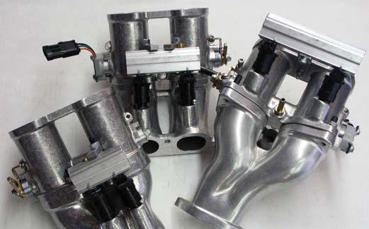
10 The Space Saver Manifolds installed in a similar manner to what was shown in the manual. The major difference is the use of the Space Saver style linkage and manifolds. This enables throttle bodies machined for injectors to be used within a sedan engine compartment. The TPS will now be on the left side throttle body (drivers side) and the injectors will be inboard. There are two extensions used on the aluminum linkage arms to correctly align the linkage rods. Refer to the above photo for a completed view of a Space Saver Manifold installation. Extension used to correctly align the linkage rods. The TPS switch will now be on the left side throttle body.

11 CAUTION - CLEAN AND FLUSH YOU GAS TANK BEFORE INSTALLING YOUR NEW FUEL LINES. THIS IS AN ABSOLUTE MUST! YOUR FUEL SYSTEM MUST BE CLEAN TO OPERATE CORRECTLY! Fuel Diagram GAS TANK 3/8" Hose 1/2" Hose FUEL FILTER 1/2" Hose IMPORTANT! USE CLAMPS AT ALL FUEL LINE CONNECTIONS, AND BLUE LOCTITE ON ALL THREADS. 3/8" Hose To Wire Harness FUEL PUMPS To Chassis* 3/8" Hose *DO NOT CONNECT NEGATIVE SIDE TO HARNESS! 3/8" Hose Fitting 3/8" Hose Fitting FUEL RAIL ASS. CYLINDERS 3-4 FUEL RAIL ASS. CYLINDERS 1-2 3/8" Hose Fuel Sensor To Wire Harness "ALL SALES AS IS"
12 Aluminum Linkage Arm #3400 Left Hand Thread Heim Joint #3348 Gold Left Hand am Nut # /2" Threaded Hex Rod # /2" #3390 Silver Right Hand Jam Nut #3397 Right Hand Thread Heim Joint #3347 Left Side A/C Base #3414 Dual Throttle Body Linkage Installation Right Side A/C Base #3413 Throttle Shaft Centering Spring #3364 (spring goes in the end of the cross bar) (spring goes in the end of the cross bar) Lock Nut (8 x 12) #3363 Cross Bar (actual length not shown) Cross Bars are available in many different lengths! 20 1/8", 21 1/8", 21 3/4" Throttle Shaft Centering Spring #3364 Lock Nut (8 x 12) #3363 Swivel Ball Joint # /8" Extensions #3395 Aluminum Throttle Cable Bracket #3403 (must go on before Aluminum Linkage Arms. Locates one hex degree down from Linkage Arms.) *Certain Kits receive Heim Joint Extensions. If your kit does not have them, disregard this information. The extensions are used to properly align the Threaded Hex Rod when using straight intake manifolds. The extensions are threaded onto both bottom Heim Joints (IDA) Receive 8 6 x A/C Base Nuts 3201-FRD Carb Kit 10 x32 Heim Joint Lock Nut #3399 IDF & DRLA Linkage Arm #3406 2" Extensions # *The Linkage Arms should be pointing inwards at about a 45 degree angle once installed on the end of the throttle shafts. *Linkage Arms & Throttle Cable Bracket are held in place with Allen set screws Barrel Clamp # /8" Heim Joint Extension # x 10 Lock Nut 10 x32 Heim Joint Lock Nut # x32 Heim Joint Lock Nut #3399 IDF & DRLA Linkage Arm #3406 Swivel Ball Joint #3360 Aluminum Linkage Arm #3400 Left Hand Thread Heim Joint #3348 Gold Left Hand am Nut # /2" Threaded Hex Rod # /2" #3390 Silver Right Hand Jam Nut #3397 Right Hand Thread Heim Joint #3347
13 IMPORTANT INFORMATION Make sure to fit your header to the Engine BEFORE any aftermarket coating. Customer assumes any responsibility for the header, after coating.


14 Hide-away Turbo Assembly Instructions Here you can see some before and after pics of some Engine Sheet Metal that has been modified to run on a Turbo System. The following pictures show the proper assembly of Turbo Drain Pipe, and the next two pages feature the assembly of the entire Turbo System. (Turbo Rotated to show Fittings)
15 Turbo Intake Clamps Rear Engine/Baja Turbo Diagram Pipe Turbo Intake Clamps Cover Cover Gaskets Turbo Intake Hose To Wastegate* Turbo Intake Hose Turbo Intake Clamps Cover Cover Gaskets Throttle Body Turbo Oil Line Kit Throttle Body Turbo Intake Clamp Turbo Exhaust Pipe Turbo Oil Drain Kit Turbo Air Filter Fuel Pump Block Off Plate Waste Gate Boost Control Line (*To Pipe) Baja Style Turbo Header
16 Turbo Intake Clamps Hideaway Turbo Diagram Pipe Turbo Intake Clamps Cover Cover Gasket Turbo Intake Hose To Wastegate* Turbo Intake Clamps Turbo Intake Hose Cover Cover Gasket Throttle Body Turbo Air Filter Throttle Body Turbo Oil Line Kit Turbo Clamps Turbo Exhaust Pipe Turbo Charger Intake Hose Intake Tube Turbo Oil Drain Waste Gate "J" Pipe "J" Pipe Turbo Header Steel Boost Control Line (*To Pipe)
17 Engine Run-On In some applications, a situation referred to as "Run-On" will occur. This is where the engine continues to run after the ignition switch is shut off. In a run on situation, a diode can be put in line with the alternator field wire. This diode will keep voltage from leaking through to the fuel injection system. (Replacements can be purchased at Radio Shack.)
18
19
IAG Air / Oil Separator (AOS) For STi
 For STi") IAG Air / Oil Separator (AOS) For 2008-14 STi Part# IAG-ENG-7000 Tools Required: Ratchet, torque wrench, extensions, needle nose pliers, hose cutter, snips/scissors Sockets: 10mm, 12mm 13mm Wrenches: 10mm,
IAG Air / Oil Separator (AOS) For 2008-14 STi Part# IAG-ENG-7000 Tools Required: Ratchet, torque wrench, extensions, needle nose pliers, hose cutter, snips/scissors Sockets: 10mm, 12mm 13mm Wrenches: 10mm,
05-08 GT. Hellion Power Systems Mustang Kit Instructions
 Hellion Power Systems 05-08 Mustang Kit Instructions 1. Disconnect Battery 2. Drain Radiator, keep fluid for re-installation. 3. Remove air box and inlethoses. 6. Next, underneath, punch oil pan for turbo
INSTALL MANUAL D o d g e 1 2 v 6 B T A PLEASE READ ALL INSTRUCTIONS BEFORE INSTALLATION.
 PN#1045310 12V Dodge Twin Turbo Kit (I-00273) 1 INSTALL MANUAL BD Twin Turbo Kit 1994-1 9 9 8 D o d g e 1 2 v 6 B T A Part# 1045310 PLEASE READ ALL INSTRUCTIONS BEFORE INSTALLATION. * Picture as shown
SDS Continental O-200 Installation Manual Aug. 4/17
 SDS Continental O-200 Installation Manual Aug. 4/17 This manual covers the steps to install the SDS EM-5 fuel injection and ignition system components on O-200 engines. Hall Sensor and Bracket Install
Procharger Stage II Intercooled Supercharger System (11-14 GT)
") Procharger Stage II Intercooled Supercharger System (11-14 GT) Installation Time: Approximately one day. Installed on 2012 Mustang GT 5.0/Manual Required Tools 3/8 Socket Set (Standard and Metric) 1/2
Procharger Stage II Intercooled Supercharger System (11-14 GT) Installation Time: Approximately one day. Installed on 2012 Mustang GT 5.0/Manual Required Tools 3/8 Socket Set (Standard and Metric) 1/2
Pump Gas Instructions for Polaris And 800 Models. Important Information before Installing This System:
 Pump Gas Instructions for Polaris 600 700 And 800 Models Important Information before Installing This System: Before you begin your turbo install, read through these instructions to determine if you are
IAG Street Series Air / Oil Separator (AOS) For 2017 WRX
 For 2017 WRX") P IAG Street Series Air / Oil Separator (AOS) For 2017 WRX Part# IAG-ENG-7152 Tools Required: Ratchet, torque wrench, extensions, needle nose pliers, hose cutter, snips/scissors, flathead screwdriver,
P IAG Street Series Air / Oil Separator (AOS) For 2017 WRX Part# IAG-ENG-7152 Tools Required: Ratchet, torque wrench, extensions, needle nose pliers, hose cutter, snips/scissors, flathead screwdriver,
V1 Truck Manifold Turbo Kit for F-body
 V1 Truck Manifold Turbo Kit for 98-02 F-body Prep: -Remove all A/C Components, Alternator and brackets, tensioner, front bumper, front bumper foam, and front bumper support. Remove radiator and cooling
WEBER CARBURETOR TROUBLESHOOTING GUIDE
 This guide is to help pinpoint problems by diagnosing engine symptoms associated with specific vehicle operating conditions. The chart will guide you step by step to help correct these problems. For successful
IAG Street Series Air / Oil Separator (AOS) For WRX
 For WRX") P IAG Street Series Air / Oil Separator (AOS) For 2015-16 WRX Part# IAG-ENG-7152 Tools Required: Ratchet, torque wrench, extensions, needle nose pliers, hose cutter, snips/scissors, flat head screw driver,
P IAG Street Series Air / Oil Separator (AOS) For 2015-16 WRX Part# IAG-ENG-7152 Tools Required: Ratchet, torque wrench, extensions, needle nose pliers, hose cutter, snips/scissors, flat head screw driver,
Instant Chat off the main page of Or simply call our tech team at
 02-07 WRX/STI Air Oil Separator for Top Mounted Intercooler Setups 2013-02- 27 Thank you for purchasing this PERRIN product for your car! Installation of this product should only be performed by persons
AMS F1-I INTAKE MANIFOLD
 AMS F1-I INTAKE MANIFOLD The goal of AMS is to provide the highest quality, best performing products available. By utilizing research and development, and rigorous testing programs AMS will never compromise
3 October 2016 PN# V Dodge Twin Turbo Kit (I-00274) ½ D o d g e 2 4 v I S B
 ½ D o d g e 2 4 v I S B") 3 October 2016 PN#1045320 24V Dodge Twin Turbo Kit (I-00274) 1 DOWNLOAD ENHANCED INSTALL MANUALS AT dieselperformance.com BD Twin Turbo Kit 1998½- 2 0 0 2 D o d g e 2 4 v I S B Part# 1045320 PLEASE READ
3 October 2016 PN#1045320 24V Dodge Twin Turbo Kit (I-00274) 1 DOWNLOAD ENHANCED INSTALL MANUALS AT dieselperformance.com BD Twin Turbo Kit 1998½- 2 0 0 2 D o d g e 2 4 v I S B Part# 1045320 PLEASE READ
Crank Trigger Hardware Installation
 Crank Trigger Hardware Installation Step 1 - Bring the engine up to TDC and remove the crank pulley bolt. Step 2 - Install trigger wheel making sure to line up the keyway. You may need to use the bolt
QUICK FUEL TECHNOLOGY HOT ROD SERIES CARBURETORS SLAYER SERIES CARBURETORS SUPER STREET SERIES CARBURETORS
 QUICK FUEL TECHNOLOGY Installation Instructions HOT ROD SERIES CARBURETORS SLAYER SERIES CARBURETORS SUPER STREET SERIES CARBURETORS HR-580-VS 580 CFM Vac. Secondary!!! SS-680-VS 680 CFM Vac. Secondary
IAG Competition Series Air / Oil Separator (AOS) For WRX
 For WRX") P IAG Competition Series Air / Oil Separator (AOS) For 2015-16 WRX Part# IAG-ENG-7252 Tools Required: Ratchet, torque wrench, extensions, needle nose pliers, hose cutter, snips/scissors, flat head screw
P IAG Competition Series Air / Oil Separator (AOS) For 2015-16 WRX Part# IAG-ENG-7252 Tools Required: Ratchet, torque wrench, extensions, needle nose pliers, hose cutter, snips/scissors, flat head screw
IAG Competition Series Air / Oil Separator (AOS) For 2017 STI
 For 2017 STI") P IAG Competition Series Air / Oil Separator (AOS) For 2017 STI Part# IAG-ENG-7251 Tools Required: Ratchet, torque wrench, extensions, needle nose pliers, hose cutter, snips/scissors, flat head screw driver,
P IAG Competition Series Air / Oil Separator (AOS) For 2017 STI Part# IAG-ENG-7251 Tools Required: Ratchet, torque wrench, extensions, needle nose pliers, hose cutter, snips/scissors, flat head screw driver,
INSTALLATION INSTRUCTIONS FUEL RAIL
 INSTALLATION INSTRUCTIONS FUEL RAIL MITSUBISHI EVO X Document# 19-0067 Support: info@radiumauto.com WARNING: DON'T SMOKE OR WORK WITH OPEN SPARKS WHILE WORKING ON THE FUEL SYSTEM PREPARING THE VEHICLE:
TURBO KIT INSTRUCTIONS
 Revision 12/20/10 TURBO KIT INSTRUCTIONS This turbo kit consists of the necessary parts to upgrade or add a turbo to your 22R/RE/RET. This kit may require some fabrication to address your particular application
IAG Street Series Air / Oil Separator (AOS) For WRX & WRX STI
 For WRX & WRX STI") IAG Street Series Air / Oil Separator (AOS) For 2006-07 WRX & 2004-07 WRX STI Part# IAG-ENG-7150 Tools Required: Ratchet, torque wrench, extensions, needle nose pliers, hose cutter, snips/scissors, flat
IAG Street Series Air / Oil Separator (AOS) For 2006-07 WRX & 2004-07 WRX STI Part# IAG-ENG-7150 Tools Required: Ratchet, torque wrench, extensions, needle nose pliers, hose cutter, snips/scissors, flat
Gen4 EFI System. Completely redesigned with an extensive new list of features and all new software.
 Gen4 EFI System Completely redesigned with an extensive new list of features and all new software. Increase Power Low-End Torque Throttle Response Cleaner Emissions Increase MPG Easy Starting Take full
Installation Instructions Diesel Nitrous System (#82028)
") Installation Instructions Diesel Nitrous System (#82028) Thank you for choosing ZEX. If at any time you have questions regarding this or any of our products, please call our Nitrous Help support line at
Installation Instructions Diesel Nitrous System (#82028) Thank you for choosing ZEX. If at any time you have questions regarding this or any of our products, please call our Nitrous Help support line at
2006 Honda Civic SI Supercharger Kit Installation Instruction Kit #
 2006 Honda Civic SI Supercharger Kit Installation Instruction Kit #350-091 3239 MONIER CIRCLE, STE.5 RANCHO CORDOVA, CA 95742 916.635.4550 FAX 916.635.4632 www.ct-engineering.com INS-157 VERSION: 3.25.2009
Instant Chat off the main page of Or simply call our tech team at
 08+ Rotated Tuner Kit for Garrett GT Turbos 2016-11-03 Thank you for purchasing this PERRIN product for your car! Installation of this product should only be performed by persons experienced with installation
Instant Chat off the main page of Or simply call our tech team at
 Subaru WRX/STI Air Oil Separator for Front Mounted Intercooler Setups 2013-02- 22 Thank you for purchasing this PERRIN product for your car! Installation of this product should only be performed by persons
IAG Street Series Air / Oil Separator (AOS) For WRX & WRX STI
 For WRX & WRX STI") IAG Street Series Air / Oil Separator (AOS) For 2006-07 WRX & 2004-07 WRX STI Part# IAG-ENG-7100 Tools Required: Ratchet, torque wrench, extensions, needle nose pliers, hose cutter, snips/scissors, flat
IAG Street Series Air / Oil Separator (AOS) For 2006-07 WRX & 2004-07 WRX STI Part# IAG-ENG-7100 Tools Required: Ratchet, torque wrench, extensions, needle nose pliers, hose cutter, snips/scissors, flat
POLESTAR HS Management System
 POLESTAR HS Management System Installation Instructions This document contains the information needed to install and adjust the POLESTAR HS Engine Management System. It assumes that the system already
8 Zip Tie Zip Tie 1 Union Fitting 1 ½ ½ Union Reducer Fitting Union 1 5/8 ½ (For Plastic Intake Manifold Vehicles)
") P IAG Street Series Air / Oil Separator (AOS) For 2017 STI Part# IAG-ENG-7151 Tools Required: Ratchet, torque wrench, extensions, needle nose pliers, hose cutter, snips/scissors, flat head screw driver,
P IAG Street Series Air / Oil Separator (AOS) For 2017 STI Part# IAG-ENG-7151 Tools Required: Ratchet, torque wrench, extensions, needle nose pliers, hose cutter, snips/scissors, flat head screw driver,
ELECTRIC FUEL PUMPS P/N , , & FUEL PRESSURE REGULATOR P/N
 ELECTRIC FUEL PUMPS P/N 80000100, 80000101, & 80000102 FUEL PRESSURE REGULATOR P/N 80000103 Installation Instructions 199R10583 These instructions must be read and fully understood before beginning the
Wrenches: ⅞, 8mm, 10mm, 13mm, 19mm P. allen, Other: Electrical Tape
 IAG Street Series Air / Oil Separator (AOS) For 2008-14 STI Part# IAG-ENG-7100 Tools Required: Ratchet, torque wrench, extensions, needle nose pliers, hose cutter, snips/scissors, flat head screw driver,
Air Oil Separator for WRX
 Air Oil Separator for 2015+ WRX 2018-06-05 Thank you for purchasing this PERRIN product for your car! Installation of this product should only be performed by persons experienced with installation of aftermarket
Holley High Performance Intake System* For Port 13B Engines (Includes B 6-Port engines converted to 4-Port)
") Holley High Performance Intake System* For 1974-1978 4-Port 13B Engines (Includes 1984-85 13B 6-Port engines converted to 4-Port) Installation Instructions I-18038 Note: These instructions assume: The
Holley High Performance Intake System* For 1974-1978 4-Port 13B Engines (Includes 1984-85 13B 6-Port engines converted to 4-Port) Installation Instructions I-18038 Note: These instructions assume: The
Installation Instruction for '84-'89 Nissan 300ZX High Performance Intercooler System (Part No )
") Installation Instruction for '84-'89 Nissan 300ZX High Performance Intercooler System (Part No. 2-124) Page ii DCB (06/14/02 12:19 AM) Version 1.0 Page iii Table of Contents 1. TOOLS REQUIRED...1 2. INSTALLATION
Installation Instruction for '84-'89 Nissan 300ZX High Performance Intercooler System (Part No. 2-124) Page ii DCB (06/14/02 12:19 AM) Version 1.0 Page iii Table of Contents 1. TOOLS REQUIRED...1 2. INSTALLATION
IAG Street Series Air / Oil Separator (AOS) For WRX & WRX STI
 For WRX & WRX STI") IAG Street Series Air / Oil Separator (AOS) For 2006-07 WRX & 2004-07 WRX STI Part# IAG-ENG-7150 Tools Required: Ratchet, torque wrench, extensions, needle nose pliers, hose cutter, snips/scissors, flat
IAG Street Series Air / Oil Separator (AOS) For 2006-07 WRX & 2004-07 WRX STI Part# IAG-ENG-7150 Tools Required: Ratchet, torque wrench, extensions, needle nose pliers, hose cutter, snips/scissors, flat
Special Note About The JDM High Performance Water Pump:
 Page 1 of 30 JDM Engineering, Inc. home Call Us! 732-780- 0770 back to Installation Instructions Electric Fan Upgrade Kit Electric Fan Wiring Diagram Thank you for your purchase of the JDM Engineering
BEFORE BEGINNING INSTALLATION
 COMPLETE CHASSIS FUEL LINE KITS For 1996-2000 Honda Civic Equipped with B-Series Engine INSTALLATION INSTRUCTIONS PLEASE study these instructions carefully before beginning this installation. Most installations
Air Oil Separator for WRX/STI Top Mounted Intercooler Setups
 Air Oil Separator for 02-07 WRX/STI Top Mounted Intercooler Setups 2018-02-26 Thank you for purchasing this PERRIN product for your car! Installation of this product should only be performed by persons
STEALTH BIG AIR KIT - Yamaha Roadliner/Stratoliner and Raider
 Page: 1 If you question your abilities it may be best for an experienced service technician perform this installation. A Yamaha Service Manual would be helpful to have on hand for reference. Revision:
97-04 CHEVROLET CORVETTE C5
 97-04 CHEVROLET CORVETTE C5 IMPORTANT! WARRANTY AND INSTALLATION INSTRUCTIONS Please Forward All Information to Consumer Be sure to review the enclosed instructions prior to beginning the installation
Slingshot Rotrex Supercharger Kit
 Slingshot Rotrex Supercharger Kit This supercharger kit improves on the Slingshot by forcing more dense air into the engine and creating more power. Installation time of the supercharger depends on you
MC Xpress AB Norra Altervägen ALTERSBRUK Sweden
 Installation manual turbo kit SkiDoo/Lynx ACE 900 1 MC Xpress AB Norra Altervägen 821 945 92 ALTERSBRUK Sweden Tel: +46 911 202005 Fax: +46 911 202008 www.mcx.se Supreme of the extreme! Thank you for choosing
SLP Camaro ZL1 STAGE 3 (650 HP)
") SLP - 2012 Camaro ZL1 STAGE 3 (650 HP) PART #26002 PACKING LIST Before installation, use this check list to make sure all necessary parts have been included. ITEM QTY CHECK PART NUMBER DESCRIPTION 1. 1
SLP - 2012 Camaro ZL1 STAGE 3 (650 HP) PART #26002 PACKING LIST Before installation, use this check list to make sure all necessary parts have been included. ITEM QTY CHECK PART NUMBER DESCRIPTION 1. 1
Installation Instruction for '84-'89 Nissan 300ZX High Performance Intercooler System (Part No )
") Installation Instruction for '84-'89 Nissan 300ZX High Performance Intercooler System (Part No. 2-124) Routing of the Intercooler Pipe It is necessary to follow the exact sequence of the installation
Installation Instruction for '84-'89 Nissan 300ZX High Performance Intercooler System (Part No. 2-124) Routing of the Intercooler Pipe It is necessary to follow the exact sequence of the installation
Scion FR-S ZN6. GTX2867R Gen2 (Internal Wastegate) Installation Instructions GPP P/N #
 Installation Instructions GPP P/N #") TURBO KIT Scion FR-S ZN6 Subaru BRZ ZC6 GTX2867R Gen2 (Internal Wastegate) Installation Instructions GPP P/N # 11518000 Vehicle Type Chassis Code Engine Code Transmission Model Year Scion FR-S DBA-ZN6
TURBO KIT Scion FR-S ZN6 Subaru BRZ ZC6 GTX2867R Gen2 (Internal Wastegate) Installation Instructions GPP P/N # 11518000 Vehicle Type Chassis Code Engine Code Transmission Model Year Scion FR-S DBA-ZN6
Installation Instructions Dual Perimeter Plate Nitrous System (#82185)
") Installation Instructions Dual Perimeter Plate Nitrous System (#82185) Thank you for choosing ZEX. If at any time you have questions regarding this or any of our products, please call our ZEXTEK support
Installation Instructions Dual Perimeter Plate Nitrous System (#82185) Thank you for choosing ZEX. If at any time you have questions regarding this or any of our products, please call our ZEXTEK support
Installation Instructions
 Installation Instructions for 15912 to 15916 Electric Fuel Pumps & Fuel Pressure Regulators Installation Instructions WARNING! These instructions must be read and fully understood before beginning the
SKID MARK GARAGE. Axillary Fuel Supply
 1 SKID MARK GARAGE Axillary Fuel Supply *Disclaimer: Our Axillary Fuel kits are designed to fit most late model GM vehicles with minimum modifications. While not quite a universal kit for all, it has been
Fuel Delivery Requirements
 held Controller the Go EFI System creates a base fuel MAP to get the engine running. Then the self tuning programming will fine tune the MAP to produce optimum power and performance. Through the use of
ZX-14 Stage I Turbo Kit
 62910 Peerless Ct. Bend, OR 97701 Phone 541.385.0706 Fax 541.382.9406 ZX-14 Stage I Turbo Kit WARNING: This turbo kit is for OFF-ROAD RACING use ONLY. Advisement: These instructions are written to be comprehensive
Instruction Manual. Fuel Injection. for the following Go EFI Systems Go Street EFI System Easy-Street EFI System Kit Contents
 This Quick Start Manual is designed to get you up and running with the Go Street Kit and either the 40003 Fuel Command Center or the 40005 Inline Fuel Delivery Kit. The FiTech Go EFI System is the industry's
Part# PLEASE READ ALL INSTRUCTIONS BEFORE INSTALLATION.
 16 November 2009 HPCR Dodge Twin Turbo Kit #1045430 1 BD Twin Turbo R700 Kit 2003-2007 Dodge HPCR ISBe Installation Instructions Part# 1045430 PLEASE READ ALL INSTRUCTIONS BEFORE INSTALLATION. UNLESS AN
INSTRUCTIONS. #82028 Diesel Nitrous System. Thank you for choosing ZEX products; we are proud to be your manufacturer of choice.
 1 INSTRUCTIONS #82028 Diesel Nitrous System Thank you for choosing ZEX products; we are proud to be your manufacturer of choice. Why our nitrous system is better: 2 Performance enthusiasts know the potential
INSTRUCTIONS. #82044 Race Diesel Nitrous System
 INSTRUCTIONS #82044 Race Diesel Nitrous System Thank you for choosing ZEX products; we are proud to be your manufacturer of choice. Kit Parts List Description Qty. Description Qty. Nitrous Solenoid 2.088
Instant Chat off the main page of Or simply call our tech team at
 Adjustable Fuel Pressure Regulator Kit for 2008+STI 2018-10-03 PSP-FUL-301 Thank you for purchasing this PERRIN product for your car! Installation of this product should only be performed by persons experienced
SHELBY GT500
 2007-2009 SHELBY GT500 Removal of Factory Unit WARNING: 1. Radiator fluid must be handled properly. Please observe local ordinances with regards to handling and disposal. 2. Allow vehicle and components
PIMP Ford 5.0 Harness Installation Manual. Part Number: PM-75
 PIMP Ford 5.0 Harness Installation Manual Part Number: PM-75 Ron Francis Wiring 200 Keystone Rd Suite 1 Chester, PA 19013 800-292-1940 www.ronfrancis.com Pre-Installation Notes: This system is designed
Rotated Tuner Kit for Garrett GT Turbos
 Rotated Tuner Kit for Garrett GT Turbos 031411 Thank you for purchasing the PERRIN performance rotated turbo kit. Installation of this turbo should only be performed by persons experienced in the installation
96-04 tt. Hellion Power Systems Mustang Twin Turbo Kit Instructions
 96-04 tt Hellion Power Systems 1996-2004 Mustang Twin Turbo Kit Instructions 1. Disconnect battery and elevate front end of car on either Jack stands or a lift if available 2.Lock steering wheel and remove
STEP 1 STEP 2. Disconnect the negative terminal from both batteries.
 TROUBLESHOOTING: Please read and understand all installation instructions before proceeding with the installation. If you have questions during the installation of this product, please email H&S Motorsports
R35 GTR ALPHA X TURBO KIT INSTALLATION INSTRUCTIONS
 R35 GTR ALPHA X TURBO KIT INSTALLATION INSTRUCTIONS 04 06 09 10 14 21 30 31 34 Turbo Kit Packaging Information Engine Mount Installation Exhaust Manifold Installation Heat Shield Exhaust Manifold Shield
1996+ Yamaha G16 / G22 Yamaha G29/YDRA Drive
 Vegas Carts & Performance 2995 Coleman St North Las Vegas, NV 89032 702-530-7753 VegasCarts.com 625cc Big Block Installation Instructions 1996+ Yamaha G16 / G22 Yamaha G29/YDRA Drive Revised 8/6/2018 1
KIT # CSS-C SUSPENSION LIFT KIT
 14385 Veterans Way Moreno Valley, CA 92553 Phone: (951) 571-0212 Fax: (951) 571-0215 2001-2010 CHEVROLET SILVERADO 1500 AND 2500 HD 4WD AND 2WD PICK-UP 1999-2010 CHEVY 2500 4WD PICK-UPS 2001-2010 2500
Stratified Aux fuel system ecoboost 2.0
 Stratified Aux fuel system ecoboost 2.0 Additional Fuel Injection System Installation and User Guide Stratified Aux Fuel System Installation and User Guide -1-0204-0021.1 Thank you and congratulations
Corvette Stage X Twin Turbo Installation. Please read the entire instructions as we ve made many changes.
 Corvette Stage X Twin Turbo Installation Please read the entire instructions as we ve made many changes. Disconnect battery. Remove plastic fuel rail covers over the valve cover. Remove Air Box in front
HI-FLOW FUEL RAIL. Installation Instructions for: Part Numbers , ,
 HI-FLOW FUEL RAIL Installation Instructions for: Part Numbers 25-100, 25-103, 25-112 ADVANCED ENGINE MANAGEMENT INC. 2205 126 TH Street, Unit A Hawthorne, CA. 90250 Phone: (310) 484-2322 Fax: (310) 484-0152
3.4L V6 SUPERCHARGER 7 TH INJECTOR KIT
 Part Number: 00602-17620-260 00602-17620-261 00602-17620-263 00602-17620-264 00602-17620-274 00602-17620-275 00602-17620-276 Section I Installation Preparation Kit Contents Item # Quantity Reqd. Description
Backwater Performance Systems Large Vanguard Mikuni Twin Carburetor Kit
 Backwater Performance Systems Large Vanguard Mikuni Twin Carburetor Kit 1. Throttle Cable Twin (CKC-41) 2. Carburetor VM30mm (CKC-40) 3. Loctite 242.5mL (A-210) 4. Air Cleaner Filter 6000 (EC-86) 5. Rev
Fuel Injection. Instruction Manual
 FiTech TM Fuel Injection Instruction Manual for the following Go EFI Systems 30001, 30002, 30004, 30012, 30061, 30062 & 30064 This Quick Start Manual is designed to get you up and running with the Go EFI
03-04 Mach 1. Hellion Power Systems Mach 1 Kit Instructions
 Hellion Power Systems 03-04 Mach 1 Kit Instructions Part 1 Hellion recommends that the front suspension system be installed either by trained professionals or by 5.Remove rack bolts K-Member Installation
Not required for most applications. Not required for most applications. High pressure ( provided) High pressure ( provided)
 High pressure ( provided)") ELECTRIC FUEL PUMPS P/N 12-801-1, 712-801-1, 12-802-1, 12-802-2, 712-802-1, 12-812, 12-815-1, & 712-815-1 FUEL PRESSURE REGULATORS P/N 12-500, 12-501, 12-803, 12-803BP, 12-804, & 15812NOS Installation
ELECTRIC FUEL PUMPS P/N 12-801-1, 712-801-1, 12-802-1, 12-802-2, 712-802-1, 12-812, 12-815-1, & 712-815-1 FUEL PRESSURE REGULATORS P/N 12-500, 12-501, 12-803, 12-803BP, 12-804, & 15812NOS Installation
FULL LENGTH HEADERS/ CATTED HEAD PIPES
 INSTALLATION INSTRUCTIONS INS232 2016-2018 CAMARO 6.2L V8 FULL LENGTH HEADERS/ CATTED HEAD PIPES Part #4044 and 40440 Special Tools required: 10mm, 12mm, 13mm, 15mm Socket and Wrenches, Pliers, Saw, Welder
GT-R Alpha 10/12 Turbo Kit
 GT-R Alpha 10/12 Turbo Kit Instructions V6 The goal of AMS is to provide the highest quality, best performing products available. By utilizing research and development, and rigorous testing programs AMS
FUEL INJECTION SYSTEM - MULTI-POINT
 FUEL INJECTION SYSTEM - MULTI-POINT 1988 Jeep Cherokee 1988 Electronic Fuel Injection JEEP MULTI-POINT 4.0L Cherokee, Comanche, Wagoneer DESCRIPTION The Multi-Point Electronic Fuel Injection (EFI) system
Step 6: Remove and save the MAP sensor for later use. Step 7: Remove the passenger side intercooler pipe and the EGR intake manifold.
 LBZ Twin kit Install Step 1: Disconnect both batteries. Step 2: Drain coolant and oil also remove passenger side inner fender. Step 3: Remove intake box and piping. (Remove and save the MAF sensor in the
All cores due 30 days after invoice date - no credit after 60 days.
 NO WARRANTY STATEMENT High performance parts & products no warranty policy: The purchaser understands and recognizes that high performance diesel products and services sold by INDUSTRIAL INJECTION SERVICE.
99-04 GT. Hellion Power Systems Mustang GT Kit Instructions
 Hellion Power Systems 99-04 Mustang GT Kit Instructions Part 1 Hellion recommends that the front suspension system be installed either by trained professionals or by 5.Remove rack bolts K-Member Installation
Slide the billet aluminum cap over the bushing and secure with the 3/8-16 x 2 1/2 socket head allen and locknuts provided.
 Slide the billet aluminum cap over the bushing and secure with the 3/8-16 x 2 1/2 socket head allen and locknuts provided. Put the urethane bushings into the upper antiroll-bar-link eyebolt. Coat the bushings
First, check and record the camber and caster readings, they will be adjusted later.
 First, check and record the camber and caster readings, they will be adjusted later. The caliper-mounting bosses are machined perpendicular to the spindle so they are an excellent place for the level.
Huron Speed Products Twin Turbo Install Gen 2 CTS-V (09-15)
") Huron Speed Products Twin Turbo Install Gen 2 CTS-V (09-15) The following install guide is simply that, a guide to help you with installation. It is by no means the exact method to perform installation,
Huron Speed Products Twin Turbo Install Gen 2 CTS-V (09-15) The following install guide is simply that, a guide to help you with installation. It is by no means the exact method to perform installation,
Shotgun Double Barrel HPFP install guide
 Shotgun Double Barrel HPFP install guide Thank you for your purchase of the VTT Shotgun Double Barrel HPFP upgrade! First thing to do when you open your box is to make sure all parts are in their respective
CAUTIONS AND WARNINGS
 FIREWALL FORWARD FUEL LINE KITS For 1996-2000 Honda Civic Equipped with B-Series Engine INSTALLATION INSTRUCTIONS PLEASE study these instructions carefully before beginning this installation. Most installations
Summit Racing MAX-efi500
 Not legal for sale or use on pollution controlled vehicles Installation and Adjustment Instructions for Summit Racing MAX-efi500 Throttle Body System P/N SUM-240500 Please read the full instructions before
Cut zip ties and remove 2 plastic wiring harness brackets.
 TROUBLESHOOTING: Please read and understand all installation instructions before proceeding with the installation. Included parts: 1 - New Bosch Cp3 Pump 1 - HSM Pulley 1 - Serpentine Belt 1 - Pump Bracket/
DESCRIPTION MECHANICAL FUEL PUMP FUEL FILTER HIGH PRESSURE (35-90 PSI) HIGH PRESSURE (35-90 PSI) (STEEL/INCLUDED)
 HIGH PRESSURE (35-90 PSI) (STEEL/INCLUDED)") Edelbrock EFI Universal Fuel Sump System - Adjustable Part #36031, 36032, 36033, 36034 INSTALLATION INSTRUCTIONS PLEASE study these instructions carefully before beginning this installation. This installation
Edelbrock EFI Universal Fuel Sump System - Adjustable Part #36031, 36032, 36033, 36034 INSTALLATION INSTRUCTIONS PLEASE study these instructions carefully before beginning this installation. This installation
DISTRIBUTORLESS IGNITION SYSTEM Installation and Adjustment Instructions
 DISTRIBUTORLESS IGNITION SYSTEM Installation and Adjustment Instructions 1.0 INTRODUCTION: Congratulations on your purchase of a Holley Distributorless Ignition System! Holley cannot and will not be responsible
***FOR COMPETITION USE ONLY as per US EPA regulations *** Factory Pipe Bill of Materials Kawasaki Ultra 150 Triple Pipe
 ***FOR COMPETITION USE ONLY as per US EPA regulations *** Factory Pipe Bill of Materials Kawasaki Ultra 150 Triple Pipe Item Qty Part Number Part Description 1 1 COMASM0947 Ultra 150 PTO Chamber assembly
CHALLENGER TWIN TURBO SYSTEM INSTALLATION INSTRUCTIONS
 CHALLENGER TWIN TURBO SYSTEM INSTALLATION INSTRUCTIONS 1 Verify contents of kits with supplied packing list 1) Unhook the battery. 2) Remove wheel wells & front fascia of vehicle. 3) Remove the catalytic
INTAKE SWAP INSTRUCTION MANUAL 1.Items to pick up before you begin:
 INTAKE SWAP INSTRUCTION MANUAL 1.Items to pick up before you begin: Someone to lend you a hand for about 10 minutes Intake gasket set that pertains to your year of engine Coil of your choice Spark plugs
Air Oil Separator for WRX/STI Top Mounted Intercooler Setups
 Air Oil Separator for 02-07 WRX/STI Top Mounted Intercooler Setups Thank you for purchasing this PERRIN product for your car! Installation of this product should only be performed by persons experienced
PRXB EXHAUST BRAKE MAXIMUM EXHAUST FLOW DESIGN
 MAXIMUM EXHAUST FLOW DESIGN PRXB EXHAUST BRAKE C44072/C44073/C44074/C44075/C44076 APPLICATION: 994-2002 DODGE RAM TRUCKS W/5.9L CUMMINS DIESEL ENGINES WITH MANUAL & AUTOMATIC TRANSMISSIONS STOCK DODGE
KIT CONTENTS. Multimeter or test light Wire crimpers or soldering equipment. Wire terminals & connectors 10A inline fuse
 RUSSELL FORD 5.0L COMPLETE EFI PLUMBING KIT INSTALLATION INSTRUCTIONS Please study these instructions carefully before installing your new complete fuel system kit. If you have any questions, please call
INSTALLATION INSTRUCTIONS AOS-R (Air Oil Separator-Return) Turbo Subaru and STi Document# Support:
 Turbo Subaru and STi Document# Support:") INSTALLATION INSTRUCTIONS AOS-R (Air Oil Separator-Return) 02-14 Turbo Subaru and 2015+ STi Document# 19-0102 Support: info@radiumauto.com These instructions are based on a vehicle with an OEM turbocharger
INSTALLATION INSTRUCTIONS AOS-R (Air Oil Separator-Return) 02-14 Turbo Subaru and 2015+ STi Document# 19-0102 Support: info@radiumauto.com These instructions are based on a vehicle with an OEM turbocharger
Included parts: 1 - New Bosch CP3 Pump 1 - HSM Pulley 1 - Serpentine Belt 1 - Pump Bracket/ Hardware STEP 1
 TROUBLESHOOTING: Please read and understand all installation instructions before proceeding with the installation. If you have questions during the installation of this product, please contact H&S Motorsports
Edelbrock EFI Universal Fuel Sump System - Adjustable Part #36031, INSTALLATION INSTRUCTIONS
 Edelbrock EFI Universal Fuel Sump System - Adjustable Part #36031, 36032 INSTALLATION INSTRUCTIONS PLEASE study these instructions carefully before beginning this installation. This installation can be
Shotgun Single Barrel HPFP install guide
 Shotgun Single Barrel HPFP install guide Thank you for your purchase of the VTT Shotgun Single Barrel HPFP upgrade! First thing to do when you open your box is to make sure all parts are in their respective
FRS/BRZ Air Oil Separator (AOS) Installation Manual
 Installation Manual") FRS/BRZ Air Oil Separator (AOS) Installation Manual Eric Hazen Rev. 2 Overview: Detailed instructions on installing the AOS for the FRS/BRZ/GT86. Difficulty: Beginner Time required: 1-3 hours depending
FRS/BRZ Air Oil Separator (AOS) Installation Manual Eric Hazen Rev. 2 Overview: Detailed instructions on installing the AOS for the FRS/BRZ/GT86. Difficulty: Beginner Time required: 1-3 hours depending
460cc Do-It-Yourself Assembly Guide
 2995 Coleman St North Las Vegas, NV 89032 702-530-7753 702-643-7517 FAX VegasCarts.com 460cc Do-It-Yourself Assembly Guide *DIY Engines do not come with a warranty, these kits are intended for experienced
LML 3 Y-Bridge Kit or High Flow Intake Bundle Package
 2011-2016 LML 3 Y-Bridge Kit or High Flow Intake Bundle Package Covers installation of PN s: WCF100607, WCF100691, WCF100716, & WCF100353 Note: This Kit is for off road competition use only! Overview-
Installation Instructions
 Installation Instructions Jeep JK Unlimited (2007 Present) Mounting Bracket and Air Line System Kit for ARB On-Board Twin Air Compressor (CKMTA12) Made in the USA Kit Contents: 1 Bracket for ARB Compressor
Disconnect the breather tube from the air cleaner outlet duct.
 Disconnect the breather tube from the air cleaner outlet duct. Disconnect the IAT sensor harness connector. Remove the air cleaner outlet duct retaining wingnut. Separate the air cleaner outlet duct from