Table of Contents. Tail Wheel Assembly Installation.. page 01. Stabilizer Installation.. page 02. Fin Installation.. page 03
|
|
|
- Jerome Williamson
- 6 years ago
- Views:
Transcription
1
2 Table of Contents Tail Wheel Assembly Installation.. page 01 Stabilizer Installation.. page 02 Fin Installation.. page 03 Elevator and Rudder Hinge Installation.. page 04 Rudder Controls.. page 05 Elevator Controls.. page 07 Main Wheel Axel Installation.. page 08 Wheel Pant Installation.. page 09 Main Landing Gear Installation.. page 11 Top / Side Window Installation.. page 12 Front Windshield Installation.. page 13 Side Door Installation.. page 14 Aileron Hinge Installation.. page 14 Aileron Servo Installation.. page 15 Wing Strut Assembly.. page 17 Engine Installation.. page 20 Fuel Tank Installation.. page 21 Cowl Installation.. page 22 Radio Set Up.. page 24 Control Surface Throw.. page 24

.")

3 Tail Wheel Assembly Installation 1 factory assembled tail wheel bracket 2 wood screws 2 tail wheel control springs 1 tail wheel rudder bracket 2 small wood screws Collect the pre assembled tail wheel bracket and hardware. Position the tail wheel assembly over the fuse and mark through the holes. Secure the tail wheel assembly to the fuse using the supplied hardware, (2 x wood screws). Secure the tail wheel steering bracket to the rudder using the supplied hardware, (2 x wood screws). Make 2 small loops in the ends of the tail wheel steering springs and secure them to the bracket and steering arms. 1


4 Stabilizer Installation 1 stabilizer 1 fin Position the stabilizer over the fuse and center it using a ruler. Using a scribe or pen, carefully mark along the sides of the fuse. Remove the covering just inside these marks using a sharp Xacto knife. Re position the stabilizer over the fuse and when satisfied with the fit, glue it in place using epoxy. 2


5 Fin Installation Position the fin over the fuse and scribe a mark along the stabilizer sides. Remove the covering on the stabilizer just inside these marks. Re position the fin on the stabilizer and when satisfied with the fit, glue in place using epoxy. Use a square to hold the fin 90 degrees to the stabilizer until the epoxy dries. You may want to tape it in place. Note: Wipe away any excess epoxy using denatured alcohol. 3


6 Elevator / Rudder Hinge Installation Position and glue in place using epoxy or canopy glue all hinge points into the factory predrilled holes. Do not glue them into the stabilizer or fin at this time. Note: Check that the hinges are operating in the proper direction before the glue dries. You may want to place a small drop of light oil on the hinges so the glue will not stick to them. 4
 Using a sharp Xacto knife, remove the covering from the servo and pull pull rudder cable cut outs in both sides of the fuse. Cut the supplied pull pull cable into 2 equal lengths.")


7 Rudder Controls 1 rudder servo and mounting hardware 1 rudder wire cable 4 cable crimp fittings 4 cable clevises 4 cable clevis nuts 2 control horn trumpet bases 1 trumpet screw 2 trumpet clevises. (black plastic) Using a sharp Xacto knife, remove the covering from the servo and pull pull rudder cable cut outs in both sides of the fuse. Cut the supplied pull pull cable into 2 equal lengths. You will notice they are very long which will make it much easier to thread through the fuse later. Note: Save the scrap pieces if you want to install optional flying wires from the stab to vertical fin on both sides. Assemble the pull pull cables and clevises. Thread one cable crimp fitting over the cable. Thread the cable through the clevis and then though the crimp fitting. When satisfied with the fit, crimp the fitting. Note: You may also want to add a piece of shrink tubing to cover over the crimped joint. Install the rudder servo inside the fuse using the supplied hardware with your radio in the center position of the servo rail inside the fuse. The rudder has 2 trumpet bases that screw together through the rudder. Position on trumpet base at the edge of the rudder beveled edge ¾ from the bottom of the rudder. Mark the spot and drill 3/32 dia. hole through the rudder. Install the trumpets with the supplies hardware. Do not over tighten the screws. Note: Strengthen the holes by applying a few drops of thin CA glue in both holes to reduce the amount of balsa compression. Install the rear rudder clevises onto the trumpets. 5
8 Thread the pull pull cable through the cut outs in the sides of the fuse and up to the rudder servo already installed. Thread all the parts, crimp fitting and clevises as you did to the other end. Temporarily attach the clevises to the rudder servos and carefully pull the cable through the clevises until they are pulling on the rudder. Pull them until they are both equal. When satisfied with the lengths, carefully crimp the cable fittings. Note: You can adjust the lengths later with the threads on the clevises. 6
 2 trumpet washers 2 trumpet screws Using the hardware supplied from your radio, install the elevator servos on both sides of the fuse.")

9 Elevator Controls 2 elevator servos and mounting hardware 2 18 inch elevator extension leads 2 threaded elevator control rods 2 servo clevises 2 control horn trumpet bases 2 trumpet clevises. (black plastic) 2 trumpet washers 2 trumpet screws Using the hardware supplied from your radio, install the elevator servos on both sides of the fuse. You will need to connect 2 x 18 inch servo leads if you are connecting the 2 servos to different receiver channels. Possition the trumpet base at the edge of the elevator beveled edge 1 1/4 from the rudder. Mark the spot and drill a 3/32 dia. hole through the elevator. Install the trumpets using the supplied hardware. Do not over tighten the screws. Note: Strengthen the holes by applying a few drops of CA glue in each hole to reduce the amount of balsa compression. Install the elevator connecting rods to the servo arms and trumpets. Note: Make sure the servo arms exit on opposite sides to ensure the elevators will travel in the same direction. If you are connecting the same receiver channel you will need a Y servo extension and one 18 inch extension. 7

10 Main Wheel Axel Installation 2 main landing gear legs 2 main wheel axels 2 axel nuts 4 axel lock collars Secure the axel to the main landing gear legs using the supplied hardware. Note: You may want to remove any burrs from the axel using a rotary tool so that the wheel collars will easily slide over the axel shaft. 8


11 Wheel Pant Installation 2 wheel pants T nuts x ½ socket head bolts 4 flat washers 4 locking washers Using a Dremel, ensure the holes in the wheel pants fit the axel nuts. Install a wheel collar on the axel, then the wheel pant with the wheel inside, then add the second wheel collar. This is a bit tricky as they all must be properly positioned together on the axel. Do not tighten the collars as yet. Note: You may need to enlarge the hole in the bottom of the wheel pant for the wheels to turn freely. 9


12 Line up the wheel pant with the graphics on the fuse so that they are parallel and even. Mark or scribe through the holes in the landing gear legs onto the wheel pants. Drill 2 x 1/8 dia. holes on these marks. Install the T nuts from inside the wheel pants. Using the supplied hardware, 2 x 6 32 bolts and washers, secure the wheel pants to the gear legs. Make sure these are very tight. Note: Be very careful that you do not cross thread any of the bolts as this may loosen the T nuts. Center the wheel in the pants and tighten the lock collars. Make sure the wheel turns freely. 10

13 Main Landing Gear Installation 1 main landing gear legs x 1/2 socket head bolts 6 lock washers 6 flat washers Using a sharp X Acto knife, carefully remove the covering from the fuse where the landing gear legs will be inserted through the fuse sides. Insert the gear legs into the fuse and secure to the mounts using 3 x 8 32 bolts and washers. You will note the T nuts have been factory installed. Tighten the bolts. Note: Be very careful that you do not cross thread any of the bolts as this may loosen the T nuts. 11


14 Top / Side Window Installation 1 top window 2 front side windows 2 rear side windows Using a sharp Xacto knife, carefully remove the covering from the top window opening on the fuse. Using canopy glue carefully add a small bead of glue to the edges of the window. Be careful not to get any glue on your fingers or the windows. Place the windows into their cut outs in the fuse and tape in place until the glue is dry. Note: You may want to add weights to hold the top window in place and masking tape on the side windows until the glue dries. 12


15 Front Windshield Installation 1 front windshield 6 small wood screws Position the front windshield over the fuse making sure it is even and slightly over the top edge of the fuse. It should also fit well along side the front edges of the leading edge of the wings and flat on the front of the fuse. Using a marker, carefully mark where the screws will go, 3 on each side. Remove the windshield and drill a small hole over these marks. Re position the windshield and secure it to the fuse using the supplied 6 wood screws. Do not over tighten the screws. Note: You may also use canopy glue to secure the windshield. Tape to hold in place until the glue dries. 13


16 Side Door Installation 2 hinge point 1 side door. Using epoxy glue, secure the hinge points into the door frame. Check for proper direction of the hinge movement. Let the glue dry before inserting the hinges into the fuse. Trial fit the door into the fuse. You may need to trim the door for the best fit. When satisfied with the fit and operation, secure the hinges into the fuse using epoxy glue. Let the hinges dry before opening the door. Aileron Hinge Installation 8 hinge point 2 ailerons The aileron hinges provided are a top quality hinge point. They have been factory drilled and fitted but are not glued in place. You will need to remove them prior to gluing. Dab a small amount of epoxy or canopy glue to each hinge and insert them into the aileron hole until the hinge is just touching against the aileron. Remember to make sure they are moving in the proper direction. Hint: use a small drop of light oil on the hinge so that the glue does not secure or clog the hinges. Wait until the glue is dry before gluing the ailerons into the wings. 14
 Using a sharp Xacto")


17 Aileron Servo Installation 2 aileron servos and mounting hardware 2 18 inch servo extensions 2 aileron servo hatches 8 small wood screws 2 control horn trumpet bases 2 trumpet screws 2 trumpet clevises (black plastic) Using a sharp Xacto knife, remove the covering around the servo wing cutouts. Install the servos onto the factory preinstalled mounting blocks using the hardware supplied with your radio. Connect an 18 inch servo extension to the servos and secure the connection with tape. Using a light string, tie a nut or small weigh to one end and drop it through the wing ribs openings until it appears in the aileron servo opening. Tape or tie the string to the servo lead and carefully pull it through the wing. 15


18 Secure the servo and hatch assembly to the wing using the supplied hardware, 4 x wood screws. Align the aileron control rods with the servo control horns and mark the location of the control trumpets so that the base is at the edge of the aileron beveled edge. Drill a 3/32 dia. hole on these marks through the aileron. Note: Strengthen the hole by applying a few drop s of thin CA glue to reduce the amount of balsa compression. Secure the trumpet assembly to the aileron. Do not over tighten the screws. Connect the control rods to the servos using the clevises or Z bends. 16


19 Wing Strut Assembly 2 main wings 1 wing tube 2 ¼ 20 nylon wing bolts 2 front wing struts (longer than rear wing struts) 2 rear wing struts 2 factory bent inter plane wing struts 2 lower wing cuffs 2 upper wing cuffs 2 lower wing strut/fuse mounting brackets x ½ socket head cap bolts x ¾ socket head cap bolts 8 inter plane wing strut brackets Slide the aluminum wing tube into the factory installed tube in the fuse. Make sure an equal amount of tube is showing on both sides of the fuse. Carefully slide and position the wings on the fuse and secure them to the fuse using the supplied ¼ 20 nylon wing bolts. You will notice a wooden dowel is provided to align the wing in the proper position on the fuse. Note: Do not crush your servo extensions between the wings and fuse. 17


, secure the wing strut to the wing strut bracket.")

20 Using a sharp Xacto knife, remove the covering from the fuse where the lower wing strut will be located. Install the wing strut bracket into the fuse using the supplied 6 32 x ¾ bolts. You will notice that the T nuts have been factory installed. Note: Be very careful that you do not cross thread any of the bolts as this may loosen the T nuts. Insert the bottom of the rear strut into the slot in the front strut and bolt together using a 6 32 x ½ bolt and lock nut. Slide the lower front wing strut cuff over the wing strut. Note: You may have to trim the cuffs with a razor saw or Dremel for the best fit. Using the supplied hardware, (6 32 x ½ bolt), secure the wing strut to the wing strut bracket. Do not tighten as yet. Slide the forward top wing strut cuff over the strut noting its direction and shape. Note: Install the struts with the airfoil shape facing the proper direction Slide the rear wing strut into the slot in the front wing strut and secure it using the supplied hardware, 6 32 x ½ bolt and nut. 18

21 Secure the wing strut assembly to the wing using the supplied hardware, 6 32 x ¾ bolts. Slide the top wing strut cuff over the bolt and secure it using clear packing tape or equal. Note : You can use clear silicon if you wish a more permanent attachment. Locate and install the inter plane wing struts brackets over the wire ends. Secure the inter plane struts to the wing using the supplied hardware, 6 32 x ½ bolts and nuts. Note: Ensure the inter plane wing struts are straight and at right angles to the wing. 19


22 Engine Installation Collect the following parts engine mounting hardware fuel lines Install your engine so the distance from the firewall to the back of your propeller is 6 3/8 inches. We recommend positioning your engine with 3º of down thrust and 2º of right thrust. Use flat washers behind the engine mount if needed. We decided to use a Super Tiger G2300 engine in our Decathlon. The kit comes with a complete traditional glow engine mount, hardware and fuel tank. First mark the center line and thrust line on the firewall using a marker. The photo shows how these lines pass through the center of the fuel line hole. Locate your engine and mount assembly. Offset your engine so the center of the prop shaft (at the propeller) lines up with the center lines on the firewall so your cowl will sit straight. Route your fuel lines and connect them to your engine. Locate where your engine throttle control rod will exit the firewall and mark it. Drill a large enough hole through the firewall. We recommend locating the throttle servo beside the rudder servo on the main servo rail. Connect the throttle linkage and make sure it is working in the proper direction and operates the carburetor linkage properly. You may want to also install a linkage to operate the engine choke if your engine is so equipped. 20


23 Fuel Tank Installation 1 fuel tank assembly 1 fuel tank mounting tray Note: Your model airplane is supplied with a Glow fuel tank and hardware kit. If you plan to use a gas engine you will have to change the stopper and fuel lines. Using the supplied hardware, assemble the fuel tank. Carefully, bend the metal tubing to avoid kinking Wrap the fuel tank in foam and tape. Note: Remember to mark which tube is for what purpose. Install the fuel tank on the mounting tray in the fuse and secure it to the fuse using Velcro straps or tape. Drill ¼ inch holes in the firewall for the fuel and vent lines 21


24 Cowl Installation 1 engine cowl 5 hardwood blocks 5 wood screws Locate and epoxy the 5 hardwood cowl blocks to the fuse firewall as shown. You may want to roughen the firewall to ensure a better bond for the epoxy. Using a black marker, put a dot in the center of the wood blocks. Make up some hole locators using card stock or heavy paper. Punch a 1/8 inch hole in one end and center this hole over the black dot on the wood blocks. Tape the other end of the card to the fuse. Slide the cowl over the engine and align the side graphics so that they are straight and even. Test fit the cowl so the distance from the front edge of the cowl to the firewall is 6¼ inches leaving 1/16 to 1/8 inches clearance of the propeller. 22


25 When satisfied, mark through the holes in the cards onto the cowl. Remove the cowl and drill 5 3/32 inch dia. holes. Cut out the necessary holes in the cowl for the proper engine cooling using a rotary tool like a Dremel. When satisfied, secure the cowl to the fuse using the supplied hardware. (5 wood screws). We recommend using a 31/2 aluminum spinner. 23
26 Radio Set Up You will need to locate your receiver and batteries on the upper plywood deck. We used foam wrap and plastic electrical straps to secure our receiver and battery. You will need a Y servo extension to connect the 2 aileron servo extensions if you are connecting to the same receiver channel. Tip: You will need to balance your model before choosing the location of your batteries. Note: The C of G is on the main wing spar. 4 1/8 from the leading edge of the wing nearest the fuse. Control Surface Throws rudder +/ elevators +/ ailerons +/ 1 1/2 low and 2 1/2 high 3/4 low and 1 1/4 high 3/4 low and 1 1/4 high Assemble the entire model and make any changes to suit. 25

27 20 Ryan Place, Unit #2, Brantford, Ontario, N3S 7S1, Canada tel: fax:
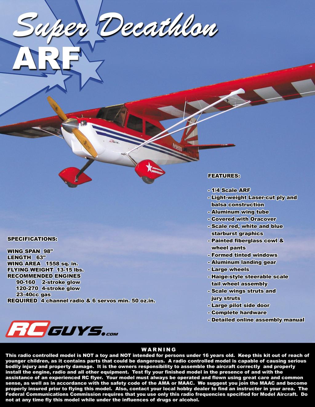
96in Super Decathlon ARF
 96in Super Decathlon ARF Instruction Manual Specifications Wingspan: 96in (2438mm) Length: 63.5 in (1614mm) Weight: Approx. 13lbs (6.5kg) 1 Dear Customer, Congratulations on your purchase of Super Decathlon
RECOMMENDED MOTOR AND BATTERY SET UP
 SPECIFICATION - Wingspan: 1404mm (55.3in) - Length: 1134mm (44. 6 in) - Flying weight: 3.2-3.4 kg - Covering type: Genuine ORACOVER - Spinner size: scale type (not included) - Radio: 4 channel minimum
Instruction Manual. Wingspan : 1400 mm (55.12 inch) : 1480 mm (58.27 inch) : 5500gr gr. : 6-9 channel/ 8 servo high torque,1 standard
 : 1480 mm (58.27 inch) : 5500gr gr. : 6-9 channel/ 8 servo high torque,1 standard") Wingspan : 1400 mm (55.12 inch) g Length : 1480 mm (58.27 inch) Weight : 5500gr - 6000gr Radio : 6-9 channel/ 8 servo high torque,1 standard Engine : GT 22 OS KIT CONTENTS: We have organized the parts
Wingspan : 1400 mm (55.12 inch) g Length : 1480 mm (58.27 inch) Weight : 5500gr - 6000gr Radio : 6-9 channel/ 8 servo high torque,1 standard Engine : GT 22 OS KIT CONTENTS: We have organized the parts
to fly. Most hardware included and all replacement parts are available.
 Instruction Manual The Thunderbolt P47 was perhaps the greatest of world war II in terms of all round performance and capability Phoenix Model has recreated a 2C - 60 class engine (or 4c 91 class) It was
RECOMMENDED MOTOR AND BATTERY SET UP
 SPECIFICATION - Wingspan: 1800mm (70.8 in) - Length: 1355mm (53.3 in) - Flying weight: 4100-4300 g - Wing area: 51 dm2 - Wing loading: 80g/dm2 - Wing type: Naca airfoils - Covering type: Genuine ORACOVER
RECOMMENDED MOTOR AND BATTERY SET UP
 SPECIFICATION - Wingspan: 1410mm (55.5 in) - Length: 1278mm (50.3 in) - Flying weight: 3.2-3.4 kg - Wing area: 41.3 dm2 - Wing loading: 75g/dm2 - Wing type: Naca airfoils - Covering type: Genuine ORACOVER
Instruction Manual BULLDOG. Wingspan : 1410 mm (55.5in) : 1450 mm (57.1in) : 4900gr gr. Weight. : 6-9 Channel/ 7 servo high torque, 1standard
 : 1450 mm (57.1in) : 4900gr gr. Weight. : 6-9 Channel/ 7 servo high torque, 1standard") Wingspan : 1410 mm (55.5in) Length Weight Radio Engine : 1450 mm (57.1in) : 4900gr - 5600gr : 6-9 Channel/ 7 servo high torque, 1standard : 1.20/ 2 stroke 1.80/ 4 stroke KIT CONTENTS: We have organized
Wingspan : 1410 mm (55.5in) Length Weight Radio Engine : 1450 mm (57.1in) : 4900gr - 5600gr : 6-9 Channel/ 7 servo high torque, 1standard : 1.20/ 2 stroke 1.80/ 4 stroke KIT CONTENTS: We have organized
Instruction Manual EXTRA 260-EP. 1075mm (42.32 in) 1000mm (39.37 in) 1100gr gr. 4 channel - 4 mini servo. Axi motor 2820
 1000mm (39.37 in) 1100gr gr. 4 channel - 4 mini servo. Axi motor 2820") 1075mm (42.32 in) 1000mm (39.37 in) 1100gr - 1400gr 4 channel - 4 mini servo Axi motor 2820 KIT CONTENTS: We have organized the parts as they come out of the box for better identification during assembly.
1075mm (42.32 in) 1000mm (39.37 in) 1100gr - 1400gr 4 channel - 4 mini servo Axi motor 2820 KIT CONTENTS: We have organized the parts as they come out of the box for better identification during assembly.
1660mm (65.4 in) 1200mm (47.2 in) 2700gr gr 6 channel - 7 servo standard 46/ 2 stroke or 52/ 4 stroke
 1200mm (47.2 in) 2700gr gr 6 channel - 7 servo standard 46/ 2 stroke or 52/ 4 stroke") Instruction Manual CESSNA-46 1660mm (65.4 in) 1200mm (47.2 in) 2700gr - 3000gr 6 channel - 7 servo standard 46/ 2 stroke or 52/ 4 stroke KIT CONTENTS: We have organized the parts as they come out of the
Instruction Manual CESSNA-46 1660mm (65.4 in) 1200mm (47.2 in) 2700gr - 3000gr 6 channel - 7 servo standard 46/ 2 stroke or 52/ 4 stroke KIT CONTENTS: We have organized the parts as they come out of the
: 7 channel - 9 servo, Hi-Torque ( Minimum 6 kg ).
.") g Wingspan : 1820mm (71.65 inches) Length : 1625mm (63.98 inches) Weight : 6900gr Engine : 25cc - 35cc Radio : 7 channel - 9 servo, Hi-Torque ( Minimum 6 kg ). KIT CONTENTS: We have organized the parts
g Wingspan : 1820mm (71.65 inches) Length : 1625mm (63.98 inches) Weight : 6900gr Engine : 25cc - 35cc Radio : 7 channel - 9 servo, Hi-Torque ( Minimum 6 kg ). KIT CONTENTS: We have organized the parts
Instruction Manual. Specification:
 Instruction Manual L O W Specification: Wingspan: 133 cm (52.3 inches) Length : 104 cm (40.9 inches) Weight : 1790gr Engine : 25-32 two stroke Radio : 4 channel - 4 servo W I N G KIT CONTENTS: We have
SIZE.120 OR 30CC SCALE 1:5 ARF
 PC21 PILATUS MK2 SIZE.120 OR 30CC SCALE 1:5 ARF SPECIFICATION - Wingspan: 1772mm (69.72in) - Length: 2019mm (79.5 in) - Flying weight: 6.4-7.2 kg - Wing area: 57.6 dm2 - Wing loading: 113g/dm2 - Wing type:
Instruction Manual. Wingspan : 2270mm (89.37 inches) : 1870mm (73.62 inches) : 7400gr gr. : 4 channel - 6 standard servo.
 : 1870mm (73.62 inches) : 7400gr gr. : 4 channel - 6 standard servo.") Wingspan : 2270mm (89.37 inches) g Length : 1870mm (73.62 inches) Weight : 7400gr - 7600gr Radio : 4 channel - 6 standard servo Engine : 25cc-35cc KIT CONTENTS: We have organized the parts as they come
Wingspan : 2270mm (89.37 inches) g Length : 1870mm (73.62 inches) Weight : 7400gr - 7600gr Radio : 4 channel - 6 standard servo Engine : 25cc-35cc KIT CONTENTS: We have organized the parts as they come
RECOMMENDED MOTOR AND BATTERY SET UP
 SPECIFICATION - Wingspan: 2000mm (78.7in) - Length: 1544mm (60.7 in) - Flying weight: 3600-3800 gr - Wing area: 66 dm2 - Wing loading: 55g/dm2 - Wing type: Naca airfoils - Covering type: Genuine ORACOVER
SBACH SCALE 1:4 ½ ARF
 SPECIFICATION - Wingspan: 1663mm (65.5 in) - Length: 1638mm (64.5 in) - Flying weight: 4700-5200 gr - Wing area: 56 dm2 - Wing loading: 85g/dm2 - Wing type: Naca airfoils - Covering type: Genuine ORACOVER
Instruction Manual. Wingspan : 1694mm (66.69 in) : 1470mm (57.87 in) : 3200gr gr. : 61 two stroke/ 71 four stroke. : 6 channel / 7 servo
 : 1470mm (57.87 in) : 3200gr gr. : 61 two stroke/ 71 four stroke. : 6 channel / 7 servo") Wingspan : 1694mm (66.69 in) g Length : 1470mm (57.87 in) Weight : 3200gr - 3800gr Engine : 61 two stroke/ 71 four stroke Radio : 6 channel / 7 servo KIT CONTENTS: We have organized the parts as they
Wingspan : 1694mm (66.69 in) g Length : 1470mm (57.87 in) Weight : 3200gr - 3800gr Engine : 61 two stroke/ 71 four stroke Radio : 6 channel / 7 servo KIT CONTENTS: We have organized the parts as they
: 6 channel - 9 servo
 g Wingspan : 2005mm (78.94 inches) Length : 1640mm (64.57 inches) Weight : 6400g - 6600g Engine : 25cc - 35cc Radio : 6 channel - 9 servo KIT CONTENTS: We have organized the parts as they come out of
I n s t r u c t i o n M a n u a l. Instruction Manual SPECIFICATION
 I n s t r u c t i o n M a n u a l Instruction Manual SPECIFICATION - Wingspan: 3200mm (125,9 in) - Length: 1650mm (64,9 in) - Flying weight: 3000gr 3200gr - Wing area: 64.5 dm2 - Wing loading: 46g/dm2
Instruction Manual book
 book SPECIFICATION Wingspan : 1,450 mm 57.09 in. Length : 1,200mm 47.24in. Weight : 3.1 kg 6.82 Lbs. Radio : 05 channels. Servo : 07 servos. Engine : 61-75 2 stroke. 91 4 stroke. Made in Vietnam. This
ASSEMBLY MANUAL. Graphics and specifications may change without notice.
 NEMESISMS: SEA 111 ASSEMBLY MANUAL Graphics and specifications may change without notice. Specifications Wing span------------------------------------- 55.9in ------------------------------- 142cm. Wing
Instruction Manual. Wingspan : 1884 mm (74.17 in) Length. Weight. Engine. : 4 channels / 5 servo standard. : 1450 mm (57.
 Length. Weight. Engine. : 4 channels / 5 servo standard. : 1450 mm (57.") Wingspan : 1884 mm (74.17 in) Length : 1450 mm (57.09 in) Weight : 4000 gr Engine : 60 two strokes Radio : 4 channels / 5 servo standard KIT CONTENTS: We have organized the parts as they come out of the
Wingspan : 1884 mm (74.17 in) Length : 1450 mm (57.09 in) Weight : 4000 gr Engine : 60 two strokes Radio : 4 channels / 5 servo standard KIT CONTENTS: We have organized the parts as they come out of the
Instruction Manual book
 book SPECIFICATION Wingspan : 1,920 mm 75.59 in. Length : 1,560 mm 61.42 in. Weight : 5 kg 11.00Lbs. Radio : 06 channels. Servo : 09 servos. Engine : 120 4 stroke. Made in Vietnam. This instruction manual
Instruction Manual. We wish you many enjoyable flights with your plane and once again thank you for your choosing a Phoenix Model product
 Instruction Manual Wing span: 1590mm (626 in) Length: 1100mm (433 in) Weight: 1500gr - 1700gr Motor: AXI 2814/10 or Motor: 500-600 w/ gear box Radio: 4 Channel / 4 servos standar Propeller: 12 x 47 We
EXTRA 330LX. Specifications: Code: SEA274. Graphics and specifications may change without notice. ASSEMBLY MANUAL
 ASSEMBLY MANUAL EXTRA 330LX Code: SEA274 Graphics and specifications may change without notice. Specifications: Wingspan---------------82.0 in (208.2 cm). Wing area---------------1349.4 sq.in ( 87.1 sq.dm).
Instruction Manual MUSTANG P51 - EP. Wingspan : 1377mm (54.21in) : 1180mm (46.46 in) : 2200gr gr. : AXI motor 2826 or 4120
 : 1180mm (46.46 in) : 2200gr gr. : AXI motor 2826 or 4120") Instruction Manual MUSTANG P51 - EP Wingspan : 1377mm (54.21in) g Length : 1180mm (46.46 in) Weight : 2200gr - 2600gr Engine : AXI motor 2826 or 4120 Radio : 4 channel / 4 servos standard KIT CONTENTS:
Instruction Manual MUSTANG P51 - EP Wingspan : 1377mm (54.21in) g Length : 1180mm (46.46 in) Weight : 2200gr - 2600gr Engine : AXI motor 2826 or 4120 Radio : 4 channel / 4 servos standard KIT CONTENTS:
RECOMMENDED MOTOR AND BATTERY SET UP
 SPECIFICATION - Wingspan: 6000mm (236.2 in) - Length: 2873mm (113.1 in) - Flying weight: 14-18 kg - Wing area: 219.4 dm2 - Wing loading: 64g/dm2 - Wing type: HQ airfoils - Covering type: Genuine ORACOVER
Instruction Manual. Wingspan : 1670mm. : 3400gr gr. : 61/75 two stroke. : 5 servo + 1 servo retract / 6 channel
 Wingspan : 1670mm g Length Weight Engine Radio : 1350mm : 3400gr - 4000gr : 61/75 two stroke : 5 servo + 1 servo retract / 6 channel KIT CONTENTS: We have organized the parts as they come out of the box
RECOMMENDED MOTOR AND BATTERY SET UP
 SPECIFICATION - Wingspan: 1420mm (55.91 in) - Length: 1370mm (53.94 in) - Flying weight: 2600-2800 gr - Wing area: 41.6 dm2 - Wing loading: 65g/dm2 - Wing type: Naca airfoils - Covering type: Genuine ORACOVER
Instruction Manual book
 Instruction Manual book SPECIFICATION Wingspan : 1,800mm. 70.87 in. Length : 1,350 mm. 53.15in. Weight : 3.6kg. 7.92lbs. Parts Listing required (not included). Glow Engine : 55-61 2 stroke. 91 4 stroke.
INSTRUCTION MANUAL BOOK
 INSTRUCTION MANUAL BOOK ITEM CODE BH57. SPECIFICATION Wingspan: 1,470 mm. 57.87 in. Length : 1,180 mm. 46.46 in. Weight : 2.7 Kg. 5.94 Lbs. Engine : 46 cu.in 2 stroke. 52 cu.in 4 stroke. Radio : 4 channels.
RECOMMENDED MOTOR AND BATTERY SET UP
 SPECIFICATION - Wingspan: 2190mm (86.2 in) - Length: 1907mm (75 in) - Flying weight: 9000-12000 gr - Wing area: 92 dm2 - Wing loading: 98g/dm2 - Wing type: Naca airfoils - Retract gear type: Air-retract
I/C FLIGHT GUIDELINES
 SPECIFICATION - Wingspan: 3500mm (137.8 in) - Length: 1650mm (64.96 in) - Flying weight: 3700-4000 gr - Wing area: 75 dm2 - Wing loading: 49g/dm2 - Wing type: HQ profile - Covering type: Genuine ORACOVER
CAP 232 ASSEMBLY MANUAL
 CAP 232 MS: ASSEMBLY MANUAL SEA 91 Graphics and specfications may change without notice. Specifications Wingspan------------------------------------ 65 in --------------------------------- 165cm. Wing
YAK54 MK2. GP/EP size.120/20cc SCALE 1:4 ¾ ARF. Instruction Manual. version. version
 Instruction Manual GP EP version version GP/EP size.10/0cc SCALE 1:4 ¾ ARF SPECIFICATION - Wingspan: 168 (66.3 in) - Length: 1605mm (63.1 in) - Flying weight: 4700-500 gr - Wing area: 54.7 dm - Wing loading:
Instruction Manual book
 Instruction Manual book SPECIFICATION Wingspan : 1,920 mm 75.59 in. Length : 1,560 mm 61.42 in. Weight : 5 kg 11.00Lbs. Radio : 06 channels. Servo : 09 servos. Engine : 120 4 stroke. Made in Vietnam. JU87-STUKA
Instruction Manual. Wingspan : 1400mm (55.12 in) : 1370mm (53.94 in) : 2600gr gr. : 4 channel / 5 servo. : / 2 stroke_52-71 / 4 stroke
 : 1370mm (53.94 in) : 2600gr gr. : 4 channel / 5 servo. : / 2 stroke_52-71 / 4 stroke") Instruction Manual 540 Wingspan : 1400mm (55.12 in) g Length : 1370mm (53.94 in) Weight : 2600gr - 2800gr Radio : 4 channel / 5 servo Engine : 46-52 / 2 stroke_52-71 / 4 stroke KIT CONTENTS: We have organized
Instruction Manual 540 Wingspan : 1400mm (55.12 in) g Length : 1370mm (53.94 in) Weight : 2600gr - 2800gr Radio : 4 channel / 5 servo Engine : 46-52 / 2 stroke_52-71 / 4 stroke KIT CONTENTS: We have organized
RECOMMENDED MOTOR AND BATTERY SET UP
 SPECIFICATION - Wingspan: 1669mm (65.7in) - Length: 1229mm (48.43 in) - Flying weight: 3300-3400 gr - Wing area: 44.2 dm2 - Wing loading: 67g/dm2 - Wing type: Naca airfoils - Covering type: Genuine ORACOVER
Instruction Manual book
 Instruction Manual book SPECIFICATION Wingspan : 1,920 mm 75.59 in. Length : 1,560 mm 61.42 in. Weight : 5 kg 11.00Lbs. Radio : 06 channels. Servo : 09 servos. Engine : 120 4 stroke. Made in Vietnam. JU87-STUKA
RECOMMENDED MOTOR AND BATTERY SET UP
 SPECIFICATION - Wingspan: 2567mm (101in) - Length: 2190mm (86.2 in) - Flying weight: 11-13 kg - Wing area: 101 dm2 - Wing loading: 99g/dm2 - Wing type: Naca airfoils - Covering type: Genuine ORACOVER -
MS:176 ASSEMBLY MANUAL. Graphics and specifications may change without notice.
 ASSEMBLY MANUAL MS:176 Graphics and specifications may change without notice. Specifications: Wing span ------------------------------98.4in (250cm). Wing area ----------------1576.4sq.in (101.7sq dm).
ASSEMBLY MANUAL. Kit features. MS:76
 ASSEMBLY MANUAL MS:76 Graphics and specfications may change without notice. Specifications: Wingspan---------------------------------------------------- 82.8 in------------------------------------- 210.3cm.
SK-50 ARF ASSEMBLY MANUAL
 SK-50 ARF ASSEMBLY MANUAL Kangke Industrial USA, Inc. 65 East Jefryn Blvd. Deer Park NY 11729 http://www.kangkeusa.com E-mail: info@kangkeusa.com Tel: 1-877-203-2377 Fax: 1-631-274-3296 Congratulations!
Lanier R/C F-4 Phantom
 Lanier R/C.40-.46 F-4 Phantom Almost Ready to Fly WARNING! THIS IS NOT A TOY! THIS IS NOT A BEGINNERS AIRPLANE This R/C kit and the model you will build from it is not a toy! It is capable of serious bodily
29% KATANA ARF ASSEMBLY MANUAL
 29% KATANA ARF ASSEMBLY MANUAL Required but not included Aircraft Specifications: 4 channel radio and supporting equipment Wing Span 84 Engine 3.2-4.2 c.i. (50-60 c.c.) Wing Area 1270 Sq. in. Fuel Tank
HERO 3D SCALE 1:6 ARF
 Instruction Manual SPECIFICATION - Wingspan: 1500mm(59 in) - Length: 1410mm (55.5 in) - Flying weight: 2100-2300 gr - Wing area: 58 dm2 - Wing loading: 39g/dm2 - Covering type: Genuine ORACOVER - Gear
ALMOST READY TO FLY. Wing Span in cm. 2
 ASSEMBLY MANUAL ALMOST READY TO FLY MS:X9 Specifications Wing Span --------------------------61.4 in ---------------------------156cm. 2 Wing Area --------------------------606.1 sq.in ------------------
RECOMMENDED MOTOR AND BATTERY SET UP
 Instruction Manual SPECIFICATION - Wingspan: 1418mm (55.8 in) - Length: 1314mm (51.7 in) - Flying weight: 2700-3200 gr - Wing area: 36.8 dm2 - Wing loading: 76g/dm2 - Wing type: Naca airfoils - Covering
LASER 200. Hand-made Almost Ready to Fly R/C Model Aircraft ASSEMBLY MANUAL
 LASER 200 Hand-made Almost Ready to Fly R/C Model Aircraft ASSEMBLY MANUAL SPECIFICATIONS: WING SPAN ----------------------------------------175CM -------------------------------- 68.75 in. WING AREA ------------------------------------------4746CM2
MS:124 ASSEMBLY MANUAL. Graphics and specifications may change without notice.
 ASSEMBLY MANUAL MS:124 Graphics and specifications may change without notice. Specifications: Wing span ------------------------------65in (165cm). Wing area -----------------658.8sq.in (42.5sq dm). Weight
the leading edge of the wing, at the fuselage - Length: 1540mm (60.6 in) 10% expo; High: 15mm up/down, 10% expo - Wing area: 40dm2
 10% expo; High: 15mm up/down, 10% expo - Wing area: 40dm2") SPECIFICATION - Gravity CG: 165-170 mm (6.5-6.7 in) Back from - Wingspan: 1400mm (55.1 in) the leading edge of the wing, at the fuselage - Length: 1540mm (60.6 in) - Control throw Ailerons: Low: 12mm up/down,
SPECIFICATION - Gravity CG: 165-170 mm (6.5-6.7 in) Back from - Wingspan: 1400mm (55.1 in) the leading edge of the wing, at the fuselage - Length: 1540mm (60.6 in) - Control throw Ailerons: Low: 12mm up/down,
ASSEMBLY MANUAL. Specifications
 ASSEMBLY MANUAL MS: SEA 82 Graphics and specfications may change without notice. Specifications Wingspan-------------------------------------- 70.9 in------------------------------ 180cm. Wing area-------------------------------------
Instruction Manual book
 Instruction Manual book SPECIFICATION Wingspan : 1,780 mm 70.08 in. Length : 1,520 mm 59.84 in. Weight : 4.8 kg 10.56 Lbs. Radio : 06 channels. Servo : 09 servos. Engine : 120 4stroke Made in Vietnam.
MS:183 ASSEMBLY MANUAL. Graphics and specifications may change without notice.
 MS:183 ASSEMBLY MANUAL Graphics and specifications may change without notice. Specifications: Wing span ------------------------------79.9in (203cm). Wing area -----------------1165.6sq.in (75.2sq dm).
ASSEMBLY MANUAL. Kit features. MS:110
 MS:110 ASSEMBLY MANUAL Graphics and specifications may change without notice. Specifications: Wing span-------------------------------------------------- 62.9 in---------------------------------------
DECATHLON. Hand-made Almost Ready to Fly R/C Model Aircraft ASSEMBLY MANUAL
 Hand-made Almost Ready to Fly R/C Model Aircraft ASSEMBLY MANUAL SPECIFICATIONS: WING SPAN ----------------------------------------172CM -------------------------------- 67.75 in. WING AREA --------------------------------------49.17Sq.dm
Specifications. Kit features.
 A S S E M B L Y M A N U A L MS:58 Graphics and Specfications may change without notice. Specifications Wingspan---------------------------------------- 70.9 in---------------------------- 182cm. Wing area----------------------------------------
RECOMMENDED EDF AND BATTERY SET UP
 SPECIFICATION - Wingspan: 1150mm (45.3 in) - Length: 1587mm (62.5 in) - Flying weight: 5.0-5.3 kg - Wing area: 40dm2 - Wing loading: 125g/dm2 - Wing type: Naca airfoils - Covering type: Genuine ORACOVER
Trainer Assembly Manual
 Trainer Assembly Manual www.pilot-rc.com -Pilot Trainer- 1 -Pilot Trainer- 2 -Pilot Trainer- 3 -Preliminary i wing & stab assembly- 1-) Locate both Plywood wing joiners (Large and small one) 2-) Insert
Assembly Manual For. Wingspan: 88 in Wing area: sp in Length: 78.8 in Engine: 50CC.
 Assembly Manual For Wingspan: 88 in Wing area: 1479.8 sp in Length: 78.8 in Engine: 50CC www.pilot-rc.com INTRODUCTION Thank you for purchasing our new 50 cc model. We strive to bring you the most complete
ASSEMBLY MANUAL. Specifications
 ASSEMBLY MANUAL MS: SEA 82 Graphics and specfications may change without notice. Specifications Wingspan-------------------------------------- 70.9 in------------------------------ 180cm. Wing area-------------------------------------
ASSEMBLY MANUAL SIZE
 SIZE.75 -.91 ASSEMBLY MANUAL MS:123 Graphics and specifications may change without notice. Specifications: Wing span ----------------------------66.9in (170cm). Wing area -----------------761.1sq.in (49.1sq
STORCH. Parts. Additional items needed to complete the Storch
 STORCH Parts Fuse with Greenhouse- (Attached) Left and right wing panel Horizontal and vertical stab 2 Wing center blocks 2 Carbon spares for wing 1 Undercarriage with wheels 2 Undercarriage shocks 2 Carbon
 WWW.SEAGULLMODELS.COM ASSEMBLY MANUAL Graphics and specifications may change without notice. Code: SEA231 Specifications: Wingspan---------------80 in (203.2 cm). Wing area---------------1235.4 sq.in (79.7
ASSEMBLY MANUAL. Specifications
 Kit features. Ready-made minimal assembly & finishing required. Ready-covered covering. Photo-illustrated step-by-step Assembly Manual. ASSEMBLY MANUAL Specifications Wingspan--------------------------------
Assembly Manual For. Wingspan: 88 in Wing area: sp in Length: 78.8 in Engine: 50CC.
 Assembly Manual For Wingspan: 88 in Wing area: 1479.8 sp in Length: 78.8 in Engine: 50CC www.pilot-rc.com INTRODUCTION Thank you for purchasing our new 50 cc model. We strive to bring you the most complete
Instruction Manual book
 Instruction Manual book ITEM CODE: BH122. SPECIFICATION Wingspan : 2,200 mm 86.61 in. Length : 1,640 mm 64.57 in. Weight : 6.5 kg 14.3Lbs. Parts listing required (not included). Radio : 8 channels. Servo
ASSEMBLY MANUAL. Kit features. MS:88
 MS:88 ASSEMBLY MANUAL Graphics and specfications may change without notice. Specifications: Wingspan-------------------------------------------------- 70.9 in--------------------------------------- 180cm.
Instruction Manual book
 book ITEM CODE:BH 72 SPECIFICATION Wingspan : 2,350 mm 92.52 in. Length : 1,730 mm 68.11 in. Weight : 6.4 kg 14.08 Lbs. Radio : 06 channels. Servo : 08 servos. Engine : OS. GT22-26cc gas. Made in Vietnam.
TUCANO 60CC SCALE 1:4 ¼ ARF. Instruction Manual. version. version
 Instruction Manual GP EP version version SCALE 1: ¼ ARF SPECIFICATION - Wingspan: 567mm (101in) - Length: 190mm (86. in) - Flying weight: 11-13 kg - Wing area: 101 dm - Wing loading: 99g/dm - Wing type:
Instruction Manual book
 book SPECIFICATION Wingspan : 2,080 mm 81.89 in. Length : 1,680 mm 66.14 in. Weight : 6.2 kg 13.64 Lbs. Radio : 06 channels. Servo : 06 servos. Engine : 30-35 CC Gas(FUJI IMVAC). Made in Vietnam. This
ASSEMBLY MANUAL. Specifications
 MS:56H Kit features. Specifications Wingspan ------------------------------ 63 in -------------------------- 160cm. Wing area ----------------------------- 728 sq.in ------------------ 47 sq.dm. Weight
SBD DAUNTLESS GP/EP SIZE ARF SCALE 1:8. Instruction Manual
 GP/EP SIZE.46-.55 ARF SCALE 1:8 SPECIFICATION - Wingspan: 1440mm (56.7in) - Length: 1140mm (44.9 in) - Flying weight: 3000-3300 g - Wing area: 42 dm2 - Wing loading: 78g/dm2 - Wing type: Naca airfoils
HARMON ROCKET III. Hand-made Almost Ready to Fly R/C Model Aircraft ASSEMBLY MANUAL
 HARMON ROCKET III Hand-made Almost Ready to Fly R/C Model Aircraft ASSEMBLY MANUAL Specifications Wingspan---------------------------------------- 50.4 in---------------------------- 128cm. Wing area---------------------------------------
SIZE 55 ASSEMBLY MANUAL
 SIZE 55 ASSEMBLY MANUAL MS:120 Graphics and specifications may change without notice. Specifications: Wing span ------------------------------63in (160cm). Wing area -----------------643.3sq.in (41.5sq
Instruction Manual book
 Instruction Manual book Item code:bh117 SPECIFICATION Wingspan : 2,100 mm 82.68 in. Length : 1,875 mm 73.82 in. Weight : 7.5 kg 16.5 Lbs. Parts listing required (not included) Radio : 08 channels. Servo
ARF TRAINER KIT ASSEMBLY MANUAL BOOMERANG EP. ALMOST READY TO FLY
 WWW.SEAGULLMODELS.COM ASSEMBLY MANUAL BOOMERANG EP ARF TRAINER KIT Graphics and specifications may change without notice. MS: 211 ALMOST READY TO FLY Specifications: Wingspan---------------56.0 in (142.2
MS:159 ASSEMBLY MANUAL. Graphics and specifications may change without notice.
 ASSEMBLY MANUAL MS:159 Graphics and specifications may change without notice. Specifications: Wing span ----------------------------61.8in (157cm). Wing area -----------------1100.5sq.in (71.0sq dm). Weight
Instruction Manual book
 Instruction Manual book SPECIFICATION Wingspan : 2,060 mm 81.10 in. Length : 1,460 mm 57.48 in. Weight : 4.8 kg 10.56 Lbs. Radio : 06 channels. Servo : 07 servos. Engine : 46 2 stroke (2pcs). Made in Vietnam.
MS:160 ASSEMBLY MANUAL. Graphics and specifications may change without notice.
 MS:160 ASSEMBLY MANUAL Graphics and specifications may change without notice. Specifications: Wing span ------------------------------70.9in (180cm). Wing area -----------------613.8sq.in (39.6sq dm).
Instruction Manual book
 Instruction Manual book ITEM CODE: BH56. SPECIFICATION Wingspan : 1,660 mm 65.35 in. Length : 1,420 mm 55.91 in. Weight : 3.8 kg 8.36 Lbs. Radio : 06 channels. Servo : 08 servos. Engine : 75 Cu.in 2 Stroke.
MS:136 ASSEMBLY MANUAL. Graphics and specifications may change without notice.
 ASSEMBLY MANUAL MS:136 Graphics and specifications may change without notice. Specifications: Wing span ----------------------------79.5in (202cm). Wing area -----------------965.7sq.in (62.3sq dm). Weight
93 AJ Laser 230z Assembly Instructions
 93 AJ Laser 230z Assembly Instructions Congratulations AJ Aircraft thanks you for the purchase of this airplane. Top grade materials and precision assembly has gone into this to make this a top quality
MEMO. No.4341 Specification: Wing Span: 29.1 (740mm) Length: 36.6 (930mm) 2. Warranty
 Length: 36.6 (930mm) 2. Warranty") MEMO No.4341 Specification: Wing Span: 29.1 (740mm) Length: 36.6 (930mm) 2 Wing Area: 299 sq.in. (19.29 dm ) Weight: 18.9oz. (536.5g) 2 Wing loading: 0.58 oz./sq.ft (27.8g/dm ) Motor: OBL 29/27-07A Warranty
MEMO No.4341 Specification: Wing Span: 29.1 (740mm) Length: 36.6 (930mm) 2 Wing Area: 299 sq.in. (19.29 dm ) Weight: 18.9oz. (536.5g) 2 Wing loading: 0.58 oz./sq.ft (27.8g/dm ) Motor: OBL 29/27-07A Warranty
FUN-50 ARF ASSEMBLY MANUAL
 FUN-50 ARF ASSEMBLY MANUAL This Manuel is the sole property of Kangke Industrial USA, Inc. Reproducing any part without the consent of Kangke Industrial USA, Inc. is a lawful violation. Kangke Industrial
ALMOST READY TO FLY. Wing Span in cm. 2
 ASSEMBLY MANUAL ALMOST READY TO FLY MS: X12 A - B Graphics and specfications may change without notice. Kit features. Specifications Wing Span ------------------------------- 42.7 in ---------------------
MS:174 ASSEMBLY MANUAL. Graphics and specifications may change without notice.
 MS:174 ASSEMBLY MANUAL Graphics and specifications may change without notice. Specifications: Wing span ------------------------------79.9in (203cm). Wing area -----------------911.4sq.in (58.8sq dm).
WE GET PEOPLE FLYING T-34
 TM WE GET PEOPLE FLYING T-34 Mentor ASSEMBLY MANUAL Specifications Wingspan:... 57.25 in (1454 mm) Length:... 45 in (1146 mm) Wing Area:... 555 sq in (35.8 sq dm) Weight:... 6 7 lb (2.7 kg 3.2 kg) Radio:...
RADIO CONTROL MODEL ASSEMBLY INSTRUCTIONS. Wasp
 RADIO CONTROL MODEL ASSEMBLY INSTRUCTIONS Wasp TRAINER Almost ready-to-fly Wingspan 1520mm Fuselage length 1105mm Engine: 40-46 2T / 52-60 4T Electric Motor: 600-700W Radio: 5 channel / 4-5 servo RC Functions:
Instruction Manual book
 book SPECIFICATION Wingspan : 2,310 mm 90.94 in. Length : 1,750 mm 68.90 in. Weight : 8.4 kg 18.48 Lbs. Radio : 06 channels. Servo : 09 servos + 2 mini servos (elevator). Engine : 45-55CC gas. Made in
 WWW.SEAGULLMODELS.COM ASSEMBLY MANUAL Graphics and specifications may change without notice. Code: SEA232 Specifications: Wingspan---------------70.9 in (180 cm). Wing area---------------810.3 sq.in (52.3
Instruction Manual book
 book ITEM CODE:BH 124 SPECIFICATION Wingspan : 2,240 mm 88.19 in. Length : 1,625 mm 63.98 in. Weight : 6,4 kg 14.08Lbs. Radio : 08 channels. Servo : 09 servos. Engine : 26-35cc Gas. Made in Vietnam. This
Instruction Manual book
 Instruction Manual book ITEM CODE: BH120. SPECIFICATION Wingspan : 1,600 mm 62.99 in. Length : 1,184 mm 46.61 in. Weight : 3.1 kg 6.82Lbs. Radio : 5 channels. Servo : 04-05 servos Engine : 46-2 stroke
Instruction Manual book
 Instruction Manual book SPECIFICATION Wingspan : 2,170 mm 85.43 in. Length : 1,760 mm 69.29 in. Weight : 6.3 kg 13.86 Lbs. Radio : 06 channels. Servo : 08 servos. Engine : 45-50CC Gas. Made in Vietnam.
 WWW.SEAGULLMODELS.COM ASSEMBLY MANUAL Code: SEA238 Graphics and specifications may change without notice. Specifications: Wingspan---------------68.9 in (175 cm). Wing area---------------776.6 sq.in (
HIGH WING MK2 GP/EP ARF SCALE
 SONIC HIGH WING MK2 GP/EP.25-.32 ARF SCALE 1:10 SPECIFICATION - Wingspan: 1340mm (52.7in) - Length: 1040mm (40.9 in) - Flying weight: 1800-2000 gr - Wing area: 27 dm2 - Wing loading: 79g/dm2 - Wing type:
Instruction Manual Book
 Book ITEM CODE: BH99. SPECIFICATION Wingspan : 2,850 mm 112.20 in. Length : 1,910 mm 75.20 in. Weight : 8.1 kg 17.82 lbs. Parts listing required (not included): Radio : 06 channels. Servo : 08 standard
ASSEMBLY MANUAL. Graphics a nd s pecifications m ay c hange w ithout n otice.
 MS: 86 ASSEMBLY MANUAL Graphics a nd s pecifications m ay c hange w ithout n otice. Specifications Wing span-------------------------------------- 70.9 in------------------------------ 180cm. Wing area--------------------------------------
JUNKERS CL1 G-BUYU. Specifications: Code: SEA275. Graphics and specifications may change without notice. ASSEMBLY MANUAL
 ASSEMBLY MANUAL JUNKERS CL1 G-BUYU Code: SEA275 Graphics and specifications may change without notice. Specifications: Wingspan---------------68.9 in (175 cm). Wing area---------------776.6 sq.in ( 50.1
Instruction Manual book
 Instruction Manual book ITEM CODE: BH39. SPECIFICATION Wingspan : 181 cm 71.26 inches. Length : 155 cm 61.024 inches. Weight : 04 kg 8.8 lbs. Servo : 9 servos. Radio : 6 channels. Engine : 91 cu.in - 2
Instruction Manual book
 book ITEM CODE: BH99. SPECIFICATION Wingspan : 2,850 mm 112.20 in. Length : 1,910 mm 75.20 in. Weight : 8.1 kg 17.82 Lbs. Radio : 06 channels. Servo : 08 servos. Engine : 35 CC gas. Made in Vietnam. This