R e f e r e n c e B o o k Fo r t h e C. K. D.
|
|
|
- Laurence Matthews
- 5 years ago
- Views:
Transcription

1 R e f e r e n c e B o o k Fo r t h e C. K. D. 1½ Litre Riley Part 1 Chassis NUFFIELD EXPORTS LTD., OXFORD, ENGLAND
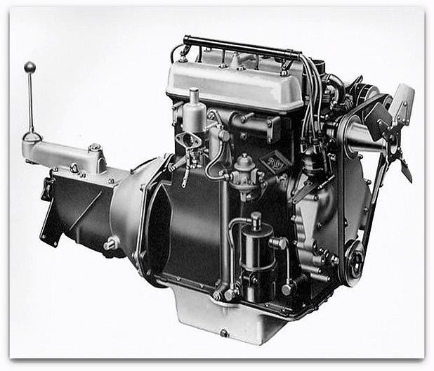
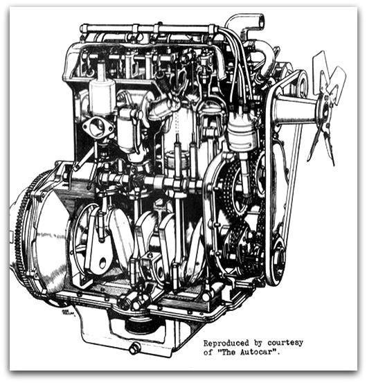
2 THE REFERENCE BOOK OF THE C.K.D. RILEY 1½ LITRE MODEL. PART 1. CHASSIS. CONTENTS:- INTRODUCTION. PAGES 1 2. TECHNICAL DATA. PAGES 3 6. ASSEMBLY OF CHASSIS PAGES LIST OF ILLUSTRATIONS. 1. ASSEMBLED CHASSIS. 2. PACKING (ENGINES) 3. PACKING (FRAMES) 4. PACKING (AXLES 1) 5. PACKING (AXLES WITH PLATFORM 2) 6. PACKING (AXLES, WHEELS & RADIATORS. 3) 7. PACKING (WINGS) 8. MAIN ASSEMBLIES. 9. ENGINE. 10.ENGINE. 11.ENGINE CUTAWAY SECTINAL VIEW 12.FRONT END. 13.REAR EMND. 14.SUSPENSION UNIT. 15.SUSPENSION UNIT. N.E.L. Sales Technical Dept. (Publication No.10)
3 THE REFERENCE BOOK OF THE C.K.D RILEY 1½ LITRE MODEL INRODUCTION In offering the new 1½ litre Riley in Completely Knocked Down form, Nuffield Export Limited are pursuing a policy which has already been followed for most of the wide range of cars which they market. This is a sincere endeavour to meet the requirements of the gradually increasing number of countries which are turning their attention to the advantage which legislation in their direction may offer. The distributor when reviewing the C.K.D. aspect of sales policy naturally raises the question as to the number of vehicles which constitute a reasonable quantity to consider upon this basis; but here it is not possible to generalize, for there are some who find it an economical proposition to order as few as 20 C.K.D. sets, while others may order as many as 5,000 or more for one model alone. The first necessity is to make a close subject of the advantages of this system, and to consider the possible savings against the landed cost of a fully built-up vehicle. Certain aspects of the matter immediately suggest themselves, a lower factory cost with additional reductions in freight, both by land and sea, reductions in handling charges, and in duty against the lower c.i.f. charges, or even preferential tariffs, in addition to which there is an increased protection against damage, deterioration, and pilferage which the C.K.D. shipment affords. These lead to the consideration of such invisible assets as a certain natural pride in a car built in one s own country where so often the influence of climatic conditions in individual needs, on taste, and on colour, demand a greater freedom to meet local requirements in regard to trimming, painting and accessories, not possible for the manufacturer who must often reach a compromise in his endeavour to meet a wide variety of world markets. All those and more, suggest ways and means by which the Completely Knocked Down form of shipment can offer attractive possibilities in cost reduction, with increased potential value, which must surely be reflected in increased sales. Nor is this arrangement by any means to the disadvantage of the country of exportation as is sometimes argued, for although the landed cost of C.K.D. shipment can show considerable reductions compared with that of a built up vehicle, this may not in pint of fact be achieved as a result of a greatly reduced factory cost. Here then is the means whereby many countries may yet find an aid to the solution of the their economic problem, and at the same time derive rich benefit from this British contribution of a unique combination of engineering experience and skill which only years of design and development can achieve. The purpose of this reference book is first to show the condition in which the vehicle can be offered in Completely Knocked Down form, and then to deal with the method of assembly recommended by the factory in conjunction with Nuffield Exports Limited.
4 The main sections cover the assembly of the chassis and body respectively. The Chassis. Four per case packing has been arrived at and illustrations 2 and 7 show clearly the method involved. Illustration 2. depicts the engine packing with batteries and ancillary equipment. Illustration 3. The frame and bonnet panels. Illustration 4, 5, 6. The progressive packing of front and rear axles with wheels and radiators. Illustration 7. The wings. There follows a detailed description of the method of assembly adopted on the Factory line with notes as to the tools and equipment generally required, an points which require special attention are fully dealt with. The Body. Details as to the assembly procedure recommended for the body are set forward in Part 2, together with notes on mounting and finishing. KLA. November 1946.
5 ENGINE. TECHNICAL DATA COVERING THE NEW 1½ LITRE MODEL. Number of cylinders. 4. Treasury Rating h.p. Capacity c.c. B.H.P. 55 b.h.p. at 4500 r.p.m. Bore. 69mm in. Stroke. 100mm in. Compression Ratio 6.7 to 1 System of cooling. Pump and thermos syphon. Maximum rebore size. Plus.040 in. Firing order. 1, 2, 4, 3. Piston clearance. Top.0026 in. to.0044 in mm. to mm. Bottom.0041 in. to.0032 in mm. to mm. Ring Gap..008 in mm. Number of compression rings. 3. Width of compression rings..078 in. 2 mm. Number of oil rings 1. Width of oil rings. 5/32 in mm. Oil pressure - (minimum figures) 19 lb./ sq.in. at 15 m.p.h. to kg./ sq.cm at 24 k.p.h. 35 lb./ sq.in. at 50 m.p.h kg./sq.cm at 80 k.p.h. 48 ln./sq.in. at 70 m.p.h kg./sq.cm. at 112 k.p.h. Gudgeon pin type. Floating - secured by circlips. Fit in piston. Light drive at room temperature. Fit in connecting rod. Push fit. Crankpin diameter (standard) in mm. Minimum diameter for regrind crankpin in mm. Connecting rod - length between centres. 8 in mm. Type of bearing - connecting rod. White metal direct to rod..002 in. to.004 in. Side clearance - connecting rod mm. to.1016 mm. Diametrical clearance - connecting rod in mm. Number of crankshaft bearings. 3. Type of bearing - main. White metal. Standard main journal diameter. Front and rear 1.75 in mm. Centre 2.76 in mm. Minimum diameter for regrind in. front and rear mm. main journals in. centre mm. Main bearings - length. Front 2 1/2 in. centre 1 7/16 in. Front mm. centre mm. rear 2 5/8 in. rear mm. End clearance main bearing..004 in. to.006 in mm. to.1524 mm
6 Diameter clearance - main bearing in. centre in. front mm. centre mm. front and rear. and rear. End thrust taken on crankshaft. Rear bearing. Number of camshaft bearings. 3. Type of bearing - camshaft. Plain. Bearing clearance - camshaft in mm. End thrust taken on camshaft. Front bearings. Camshaft drive - type. Chain to both camshafts. Valve timing markings. Crankshaft keyway vertical. Marks on chain wheels in line. Exhaust valve diameter - head and stem. 1 7/16 in. head and 5/16 in. stem mm. head and 7.93 mm. stem. Inlet valve diameter - head and stem. 1 7/16 in. head and 5/16 in. stem mm. head and 7.93 mm. stem. Valve seat angle. 45 Tappet type. Mushroom. Inlet valve clearance for timing in mm. Inlet valve opens. 9 or 2 1/3 flywheel teeth B.T.D.C. Inlet valve working clearance..003 in. hot mm. Exhaust valve working clearance..004 in. hot mm. Are guides removable. Yes. Carburetter make and type. S.U. horizontal H.2. fitted jet. No.3 needle. Clutch and Gearbox. Clutch type. 8 in. dia Borg & Beck cm. Type of facing. Special Borg & Beck. Gear ratios. Top 4.89 to 1. Third 7.23 to 1. Second 11.2 to 1. First to 1. Reverse to 1. Front Axle and Steering. Camber. 1. Castor angle. 3. Toe-in. Nil. Swivel pin inclination. 11. Track. 4 ft. 4 1/2 in. front and rear cm. Turning circle. 30 ft metres. Wheelbase. 9 ft. 4 1/2 in cm. Tyre size and pressure x 16 in. Front 22 lb./sq.in. Front kg./sq.cm. Rear 24 lb./ sq.in. Rear kg./sq.cm. Rear Axle. Type of axle. Semi-floating
7 Type of drive. Spiral bevel. Ratio to 1. Adjustment. Vernier - no shims. End play. Nil. Lash.006 in mm. NOTE: The pinion assembly is very accurately set by means of a special gauge and should not be altered without reference to our Service Department. Brakes. Type. Girling hydro-mechanical. Lining size. Front 9 3/4 in. x 1 3/4 in. x 3/16 in. Front mm. x mm. x 4.76 mm. Rear 9 3/8 in. x 1 1/2 in. z 3/16 in. Rear mm. x mm. x 4.76 mm. Springs. Front. Fitted Riley Torsionic independent front suspension. I.E. two torsion bars parallel to chassis. Length - rear. 45 1/2 in. (eye centres) cm. Width - rear. 2 in mm. Number of leaves - rear. 13 Thickness of leaves - rear. One to five 3/16 in. others 5/32 in. One to five mm. others mm. Camber - rear. Electrical. 1 7/8 in. minus 1/8 in. loaded (negative camber) mm. minus mm. loaded (negative camber) Distributor rotation. Clockwise. Manual advance. Yes. Automatic advance. Yes. Breaker gap..012 in. to.016 in mm. to.3810 mm. Plug - make and type. Champion L10.S Plug gap..030 in mm. Firing order. 1, 2, 4, 3. Ignition timing - degrees. 8 B.T.D.C. Full advance of manual control. Ignition timing - number of flywheel teeth. 2 teeth
8 Charging system. Battery - capacity, make and type. Battery earth. Lucas C.V.C. type special equipment. Dynamo C45YV. Control box R.P.91. Lucas 12 volt. 58 amp/hour. STWX9A Positive. Capacities. Sump. 10 pints litres. Gearbox. 2 pints litres. Rear axle. 2 3/4 pints litres. Cooling system. 13 pints litres. Radiator hose - top. Special pre-formed hose. Radiator hose - bottom-length and internal diameter. 2 3/8 in. x 1 1/4 in. diameter. 2 off mm x mm. Petrol tank. 12 1/2 gallons litres. General Dimensions. Overall length. 14 ft. 11 in metres. Overall height. 4 ft. 11 in metres. Overall width. 5 ft. 3 1/2 in metres. Ground clearance. 7 1/2 in cm. Total weight. 24 1/4 cwt. (dry) kg. Valve Timing. Inlet opens. Inlet closes. Exhaust opens. Exhaust closes. 9 before T.D.C. 45 after B.D.C. 56 before B.D.C. 20 after T.D.C
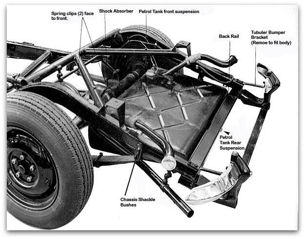
9 SEQUENCE OF OPERATIONS. The chassis frame is lifted to an assembly line or assembly bench, with means for lifting front and rear ends for fitting purposes. NOW PROCEED IN THE FOLLOWING OPEERATIONAL SEQUENCE:- Operation 1. Fit main petrol feed pipe to O/S chassis side meber. Pipe is attached to side member with 9 clips and hexagon headed screw into tapped holes. Screwdriver or 1/4 box spanner. NOTE. It is advisable at this stage to leaves the screws slack since certain of the main harness cable clips pick up on the same screws. Operation 2. Operation 3. Fit torsion bar adjusting brackets to the rear face of the brackets to be found welded to the rear side of the chassis front cross member. The adjusting brackets are located to the welded brackets with 4-5/16 bolts, nuts and external shakeproof washers. (Illustration 15). 3/8 Standard spanner. Now fit back rail to extreme rear end of chassis members to carry the rear bumper fittings and on which is also welded the stud for the petrol tank rear suspension. (Illustration 13) The back rail is attached to the chassis with 4-5/16 bolts, nuts and external shakeproof washers. Rear bumper fittings consist of the following:- 2 - Flat bumper brackets which are attached to the back rail with 4-5/16 bolts, nuts and ext. shakeproof washers. 2 - Square section jack tubes which are attached to the bumper bracket and back rail with 4-3/8-5/16 headed bolts, nuts and ext. shakeproof washers. 1 - Flat bar back rail which is attached to ends of jack tubes with 2-3/8-5/16 headed bolts, distance pieces (the distance pieces fit under the heads of the bolts on the top face of the flat bar back rail). Ext. shakeproof washers and nuts. 2 - Bumper brackets, tubular, fit from flat bumper brackets to top of chassis side members with 6-5/16 bolts, nuts and ext. shakeproof washers. NOTE. The 2 tubular bumper brackets must be removed when mounting the body. 5/16 ring spanner. 5/16 standard spanner. 5/16 box spanner. 3/8 box spanner. 3/8 standard spanner. Operation 4. Fit Harris rubber bushes to chassis frame shackle bushes as follows:- (Illustration 13) 4 - long bushes in front frame shackle bushes. 4 - short bushes in rear frame shackle bushes
10 8 - short bushes in spring eyes (4 off each spring). Operation 5. Operation 6. Operation 7. Operation 8. Bushes are pushed in by hand. Fit shock absorbers complete with arms and links to chassis side members with 2-7/16 bolts each, which screw into tapping blocks already welded in position on chassis. (Illustrations 8 and 13). 7/16 box spanner. 7/16 ring spanner. Lift rear axle and torque tube assembly into position in chassis. Remove propeller shaft driving flange, turn trunnion partly sideways in order to enter it into trunnion bush brackets (Welded on chassis cross member). (Illustration 8). Overhead pulley block, chains and rope. Connect torque tube trunnion to trunnion brackets, now fit trunnion bushes (pushed through trunnion brackets on to trunnion from outside). The trunnion bushes are attached to trunnion brackets with 4-1/4 bolts, nuts and ext. shakeproof washers. Before fitting trunnion bush covers, fit 2-3/8 bolts with washers, 1 in each side of the trunnion and tighten up, now fit the 4 bolts to each trunnion bush through bracket with heads to the outside, next fit bush covers to same bolts and fit washers and nuts. 1/4 and 3/8 standard spanners. Now fit propeller shaft driving flange on to splines of enclosed propeller shaft. Hide mallet. NOTE. This flange is held in position by intermediate propeller shaft. Operation 9. Tighten torque tube trunnion to its original position by means of the clamp bolt situated on the top of the torque tube. (Illustration 8). 3/8 standard spanner. NOTE. Rock axle to ensure its free movement in the trunnion bushes. Operation 10. Now fir spring chassis assemblies as follows:- The shackle assemblies with long pins in front position of rear spring, together with the inner shackle plate with the distance piece welded to it
11 The shackle assemblies with the short pins in the rear position of the rear springs together with the plain flat inner shackle plate. Rear springs should be fitted to the rear axle with the 2 spring leaf clips facing towards the front of the vehicle. (Illustration 13). 7/16 box spanner. 7/16 standard spanner. Clamping device A.1730-J9. NOTE. Shackle pin nuts must be left slack until the springs have been compressed almost flat. This procedure is necessary, as if nuts are tightened before springs are compressed the Harris rubber bushes will be severely damaged when load is subsequently placed on the springs. Operation 11. Before releasing compression on springs, connect shock absorber links to anchor lug on spring platform. 7/16 box spanner. NOTE. Care must be taken to ensure that the long end of the tab washer which fits on the top of the bolt locating shock absorber link to axle faces toward the front of the vehicle. Operation 12. Now tighten up shackle oin nuts. 7/16 box spanner. 7/16 standard spanner. NOTE. The shackle pin split nuts tighten straight down on to shackle plates, no washers used. Operation 13. Fit stabiliser bar and brackets to shock absorber arm brackets O/S and N/S with 4 3/8 bolts, nuts and ext, shakeproof washers. (Illustration 13). 3/8 box spanner. 3/8 standard spanner. NOTE. The stabiliser bar must face toward the rear of the car, otherwise the end brackets will foul body floor. In order to enter the bar between the shock absorbers, slacken bracket clamp bolt and tap bracket along splines towards the centre, reversing the procedure to bring the brackets up against shock absorber with the bar in position. The amount of splining showing beyond the inner side of the brackets, when fitted, should be the same. Brackets should not be taken off the bar as they have been set at the factory and the splining is so fine that it is extremely difficult without special jig to ensure that both brackets are in line. Operation 14. Fit rear road wheels complete with tyres and tubes. 1/2 brace spanner
12 Operation 15. Operation 16. Operation 17. Operation 18. Now fit petrol tank. The petrol tank is suspended in chassis at three points, i.e. at one point on each of the chassis bracing tubes and at one point on the back rail. (Illustration 13). The actual suspension components take the form of 8 rubber blocks and 4 metal plates and three bolts, one of which is already welded in position on the back rail. Care should be taken in the order of fitting of the rubber blocks and metal plates, this is as follows:- (a) On the suspension points on both bracing tubes, pass bolt through hole drilled to receive it, next fit 1 rubber block, then petrol tank, another rubber block followed by a metal plate and finally a 3/8 Simmonds nut. (b) On the rear suspension point (on back rail) proceed thus:- fit both rubber blocks then petrol tank followed by metal plate, finishing with 3/8 Simmonds nut. (c) Now tighten all nuts. 3/8 standard or box spanner. Fit brake and clutch pedals with spindle, centre distance piece, grooved taper pin, end distance piece, pedal return spring and spindle bracket. Illustration 15). Assemble the above part as follows:- The drilled centre distance piece is pushed in to the spindle, matching up pin holes, now fit grooved taper pin. Coil pedal return spring over grooved pin until the pin comes within the centre loop of the spring. The pin acts as spring anchor. Now fit brake pedal on spigotted end of spindle followed by the end distance piece. Fit clutch pedal on opposite end of the spindle. Insert spigotted end of spindle into drilled plate welded to chassis side member immediately behind front cross member. Now insert the flatted end of the spindle into spindle bracket and attach to R.H. torsion bar bracket with 2-5/16 bolts. The spindle bracket thus holds pedal assembly in position to chassis side member. 5/16 box spanner. Now fit brake cross shaft and levers to brackets welded on intermediate chassis cross member. Brake cross shaft consists of a tube with a lever welded on each end. A pegged shaft passes through the tube and is kept stationary by the peg locating in slot in bracket. The pegged shaft is kept in position with split pins, no washers are used. Pliers. Fit brake compensating lever to pivot pin welded in position on front side of intermediate cross member, secure with washer and split pin. The lever is connected beneath the cross member to the brake cross shaft lever by a hexagon adjusting tube and it is at this point that all slackness throughout the brake rodding system is taken up. About 1/8 lost motion is allowed on brake pedal to ensure master cylinder rod returns to its stop. Pliers. 3/8 standard spanner
13 NOTE. Fork ends should not be moved on rods as they have been very finely adjusted and locked at the factory. Operation 19. Fit clutch compensating shaft and levers to brackets welded in position on 2nd chassis cross member. This shaft is of the same design and fitting as brake cross shaft - see Operation 17 for details. NOTE. A clutch stop is incorporated on above shaft and a further clutch pedal return spring is fitted from compensating shaft to seat bracket on 2nd cross member. GENERAL NOTE ON BRAKE AND CLUTCH OPERATING SHAFTS, RODS ETC. The whole of this mechanism is hand fitted and thus becomes peculiar to the vehicle to which it is assembled. This careful fitting is carried out to ensure all parts work freely and that any slight irregularities in welded brackets, shafts, levers etc. which may cause binding have been eliminated. In addition, all rod fork ends have been very finely set and locked (as finely as 1/4 thread) and on no account should fork ends be removed from rods or fitted to any car other than that from which have been removed. Should it be necessary to dismantle the system - the master cylinder, complete with rods and hoses should be removed as a complete unit, by withdrawal of split pins and clevis pins. The handbrake is connected to a rod from the brake compensating lever through another rod and lever mounted on pivot pin and bracket welded on inside of R.H. chassis member - to front of vehicle and thence by cable to a pistol grip sliding lever mounted underneath of scuttle body after body has been mounted. The handbrake operates on rear wheels. Operation 20. Fit clutch withdrawal mechanism. The clutch operating shaft is splined on one end of which a fork is fitted, this fork is connected to similar fork projecting from the clutch housing through the medium of a coupling piece. The forks are attached to coupling piece with clevis pins retained in position by washers and split pins. A lever is dowelled on the opposite end of the shaft - approximately 1 1/2 from the end, this end of the shaft fits into a ball socket, which is built up on a tapped plate welded to the chassis member. From the lever, a rod with spring and adjusting nut (on lower end) passes back to clutch compensating shaft lever, whilst another rod connected to the opposite compensating lever passes back to the clutch pedal. (Illustration 8). Action:- Depression of clutch pedal causes the clutch operating shaft to take a backward rotary movement thus disengaging the clutch. 5/16 standard or box spanner. Pliers. NOTE. A return spring is fitted from the clutch pedal to R.H. torsion bar bracket. This spring is additional to that mentioned in Operation 16. Operation 21. Fit accelerator pedal (temporarily). The accelerator is mounted on pivot pin welded to the outside of the R.H. chassis side member immediately behind chassis front member
14 Pliers. Items comprising accelerator assembly are as follows and should be fitted on pivot pin in the order set down below:- (a) Steel washer. (b) Rubber washer. (c) Accelerator pedal. (d) Rubber washer. (e) Steel washer. (f) Split pin. A rubber draught excluder fits on pedal before foot pad is fitted. NOTE. THE ACCELERATOR PEDAL ASSEMBLY SHOULD NOT BE FINALLY FITED UNTIL BODY HAS BEEN MOUNTED. Operation 22. Now fit front suspension unit. Front wing stays. Road wheels. The suspension unit should be lifted to the correct height with pulley block and tackle, since a certain amount of movement is necessary to ensure locating bolts will enter holes squarely. First enter the 2-7/16 bolts which are already in position at the bottom of the suspension cradle. Now fit the 8-7/16 bolts (4 each side) from the inside towards the front. Fit all nuts and tighten with the exception of the 2-7/16 bolts at the extreme bottom (these bolts have their heads facing the front of the vehicle). Now slacken back the bolts in the torsion bar adjusting cam, this will allow the cam to hang loose. Now depress the hydraulic dampers to their fullest extent by means of a lever. With the hydraulic dampers still fully depressed with the torsion bar adjusting cam held up by hand against its stop, insert the torsion bar from the rear with the 1/2 tapped hole in the bar facing towards front of vehicle, the primary object is to enter the front and rear splined ends of the bar simultaneously at the same time retaining the hydraulic dampers in the fully depressed condition and with the torsion bar cam held up against its stop. Having entered the splines a second operator should drive the torsion bar forward by means of an aluminium or other soft metal rod 3/4-1 dia. held up against the rear end. Do not drive the torsion bar right forward but leave the rear end projecting about 1/4 beyond the face of the adjusting cam. Now insert the torsion bar retaining stud and cap into the 1/2 tapped hole in front end of the torsion bar and tighten, the tightening up will have the effect of drawing the torsion bar forward on its splines, until the rear end becomes flush with the face of the adjusting cam. The compression can be taken off the hydraulic dampers before the torsion bar retaining stud is fitted. Now tighten up nuts of the 2-7/16 bolts which were left loose. Fit the front road wheels. The front wing stays should now be fitted to suspension cradle and adjusted to the current height, which is 10 1/2, and is taken by means of a simple jug frim the top face of the front tie bar brackets (welded to suspension cradle) to the highest point of the wing stay. (Illustrations 14 and 16). Hide mallet, 2 length 3/4-1 dia. aluminium rod. 3/8 standard spanner. 5/16 box spanner. 1/2 box spanner. 3/8 brace spanner. 7/16 standard or box spanner. NOTE. It should be noted that before the torsion bars are fitted at the Factoru they undergo a test, the result of which makes them O/S and N/S, care should be taken therefore, to refit the torsion bars in those positions. Following the fitting of the
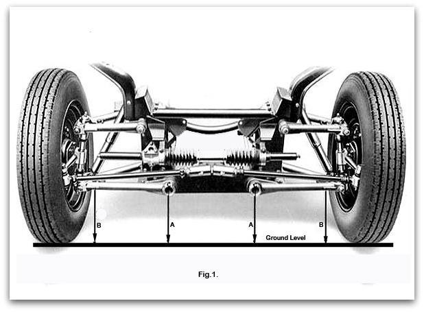
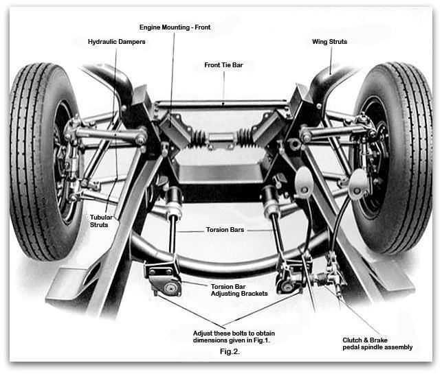
15 torsion bars the pressure can be taken off the hydraulic dampers, when it will be seen they will remain in an approximately fully extended condition, thus facilitating final adjustment when the car has been completely erected, it being simpler to lower the car by means of the adjusting cam to the correct height than to raise it by the same means, in fact, NO ATTEMPT SHOULD BE MADE TO RAISE THE CAR BY MEANS OF THE ADJUSTING CAM failure to observe this instruction will cause the adjusting cam bolt to shear. The method of final adjustment is dealt with below, but it must be borne in mind that such final adjustment is not carried out until car has been completely erected and ready for the road. PROSEDURE FOR CHECKING AND ADJUSTING THE SETTING OF THE INDEPENDENT TORSIONIC FRONT SUSPENSION. With the car resting on its wheels and tyre pressure balanced and normal, the dimensions indicated should be checked. (Illustration 14). Dimension at A should be 1 inch more than dimensions at B, measurement being taken from the centres of attachments C and D to level ground. If this difference in height is LESS than 1 inch the dimensions must be increased, the procedure being as follows:- The front of the car must be jacked up until the wheels are completely clear of the ground, the weight of the car should then be removed from the suspension gear. This point is very important and on no account must any adjustment be made to increase the dimension at A with the weight of the car on its front wheels. The adjustment at the rear of the torsion bars must now be screwed IN (Fig.2.) one complete turn. This should give a difference of height, at the forward end, of 3/4 inch. The car must no be lowered on to its road wheels again and the springing allowed to settle by rocking the fron end up and down a few times. Dimensions A and B should now be re-checked. If the difference between A and B: is now greater than 1 inch there is no need to jack the car up again in order to decrease this dimension. It is only necessary toe screw the adjusters OUT until the correct measurement is obtained. IMPORTANT NOTE. Do not on any account attempt to increase dimension A (fig.1.) without first of all taking the weight of the car off the front suspension gear. Having carefully checked the above adjustment and reset if necessary, the track should then be verified. In checking the track two or three measurements should be taken so that a mean reading can be obtained. This will allow for manufacturing variations in wheel rims. The track should be set so that mean reading shows the wheels to be parallel (measuring at hub level) and for setting the track we recommend a Dunlop track setting machine or some such apparatus that gives really accurate readings. For guidance, we would advise that, to allow for a certain amount of settling in torsion bars, our procedure when turning out new cars from the Factory is firstly to set the tyre pressures (22 lbs. to square inch). Torsion bars and track to the figures given above, and then, subsequently, to increase the torsion bar setting so that the inner point C is 2 inches above the outer point D on the other side, without making any further adjustments to the track. This means, therefore, that when the car is new, the front wheels are TOEING OUT SLIGHTLY, but when the torsion bars have settled to the correct position of the inner fulcrum being 1 inch higher than the outer, then the track will be correct. It is advised that a check is made at 500 miles, and the track set parallel with a 1 inch height variation between A and B, the torsion bar adjuster should be reset to
16 1 1/2 inch between the points A and B without making any further adjustments to the track. This will allow for a further possible settling of the torsion bars. A further check at 2,000 miles or more, the 1 inch setting on the struts with parallel track should be used. Operation 23. Operation 24. Tooling. Fit engine mounting rubbers to front suspension cradle and to 2nd chassis cross member. Lower engine to frame and bolt to mountings. Proceed as follows:- Sub assembly of mountings bolt front mounting blocks to mounting block bracket and attach assembly to R. and L.H. sides of suspension cradle 8-5/16 bolts (4 each side) with shakeproof washers.. Holes in cradle are already tapped to receive the bolts. (Illustration 15) Rear engine mounting - Take the aluminium bridge piece and place into it the steel bridge piece packing, then the rubber mounting block, secure these parts through the centre of the rubber block with the long bolt, rubber washer, steel plate and Simonds nut, plus 2-3/8 plain nuts on the studs of the rubber mounting. Screw into each end of the aluminium bridge piece a 5/16 set screw, so that it bears up against the inner packing piece. The object of these is to control the resiliency of the rear mounting as required by screwing in or out as necessary. Now secure the rear mounting assembly to the bracket welded to the chassis cross member with 2-7/16 bolts, nuts and shakeproof washers. LOWER ENGINE TO MOUNTINGS AND SECURE THUS:- Bolt front engine bearers to mountings with 2 off each side 7/16 bolts, nuts and shakeproof washers. Bolt gearbox bearer to rear mounting with 4-7/16 bolts, nuts and shakeproof washers. 7/16, 3/8 and 5/16 standard spanners. Fit front tie bar. Attach the tie bar by sliding on to welded bracket on r. and L.H. sides of suspension cradle and secure each end with 3-5/16 set screws with washers. Set screws pick up in nuts welded to underside of tie bar ends. (Illustration 15.). 5/16 spanner. NOTE. The object of the tie bar being detachable is to make possible the removal of the engine without dismantling the surrounding bodywork. Operation 25. Tooling. Connect engine steady cables. (a) Attach front steady cable to front tie bar and secure with rubber washer, steel washer and Simonds nut - tension - nearly full out (finger tight). (b) Attach rear steady cable to chassis cross member and secure as for front cable. 5/16 standard or box spanner
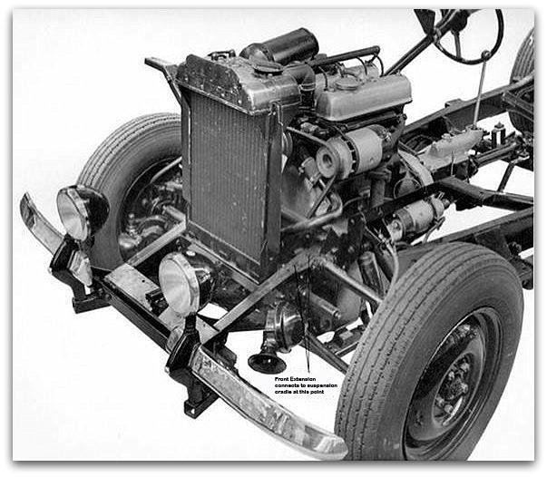
17 Operation 26. Tooling. Operation 27. Tooling. Operation 28. Tooling. Connect intermediate propeller shaft to engine/gearbox and rear driving flange. Bolt up (4 off each end) with special 3/8 bolts and Simonds nuts. 3/8 standard spanner. Now fit exhaust system. The exhaust system comprises the following sections:- (1) Exhaust pipe with metallic flexible extension - exhaust manifolds to silencer. (2) Silencer unit. (3) Pipe expansion box. (4) Tail pipe. Care must be taken that clips and rubber bushed suspension links are fitted in accordance with the following instructions, since failure to do so will cause the pipe to be set over and fouling the petrol tank will result. Proceed as follows:- 1st position. (front end of vehicle) Fit suspension link outside of welded bracket, followed by exhaust pipe clip on extreme outside (5/16 nuts and bolts). 2nd position. Fit suspension link on inside of bracket but fit the exhaust pipe clip on the outside of bracket. 3rd position. As for No.1. 4th position. As for No.1. 5/16 standard spanner. 1/4 standard spanner. 3/8 ratchet spanner - for bolts - pipe to manifold. Fit chassis front extension to suspension cradle. Proceed as follows:- (a) Secure at top position on to cradle with 6-5/16 bolts, nuts and shakeproof washers. (Illustration 8 and 12) (b) Secure at bottom position on to cradle with 4-1/4 bolts, nuts and shakeproof washers. 5/16, 1/4 and 3/8 box or standard spanner. NOTE. The front extension carries the following parts:- (1) Radiator. (2) Starting handle guide tube. (3) Horn brackets 2. (4) 2 Front jacking brackets. (5) Front bumper rail (6) 4 Bumper support brackets. (7) 2 Bumper strengthening brackets. All the above components are secured to front extension with 5/16 and 3/8 bolts, nuts and shakeproof washers. Operation 29. Tooling. Sub assemble radiator and fir to front extension. (Illustration 8 and 12). Sub assemble the following parts to studs welded to radiator bottom case, in the order as follows:- (1) Metal distance piece. (2) Large steel washer. (3) Rubber mounting - now fit radiator to front extension and continue. (4) Thin rubber washer. (5) Large steel washer. (6) 3/8 Simmonds nut. 3/8 box spanner. Operation 30. Connect radiator to engine. (a) Fit molded top hose and secure with 1 large clip on engine and 1 small clip on radiator pipe. (b) Connect at bottom with 2 hoses, 4 small clips and metal water pipe
18 Tooling. Screwdriver. NOTE. Bottom hoses are interchangeable, as are the small hose clips. NOTE. Steering mast, tube, telescopic fittings and certain electrical work are fitted or carried out after the body has been mounted

19 Illustration 1
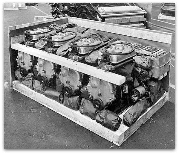
20 Illustration 2
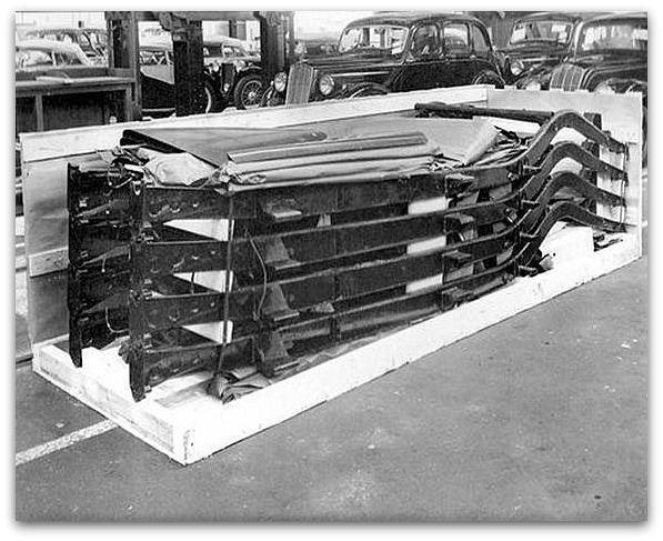
21 Illustration 3

22 Illustration 4
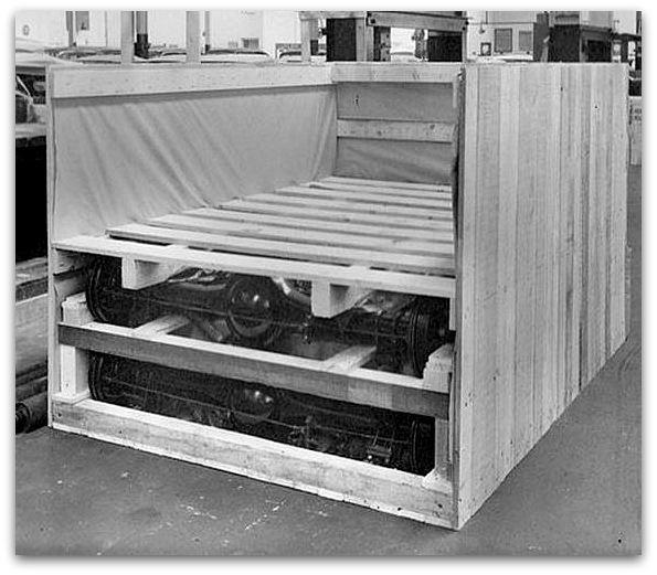
23 Illustration 5
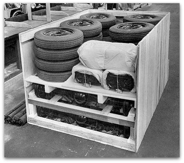
24 Illustration 6

25 Illustration 7
26 Illustration 8
27 Illustration 9

28 Illustration 10
29 Illustration 11
30 Illustration 12
31 Illustration 13
32 Illustration 14
33 Illustration 15
34
lbs sq. Camshaft bush ID 0.5 ± Clearance bush to camshaft ±
 GENERAL Cubic capacity 347 C.C. Stroke 93 mm. / 3.6614 Cylinder bore Compression ratio Max compression at kick starter speed 2 23 /32 = 2.7187 ± 0.0005 (Re-bore to + 0.02 when wear exceeds 0.008 ). Note:
MGA Twin Cam Engine Assembly.
 MGA Twin Cam Engine Assembly. The following article is a collection of notes of things to be observed in the assembling of MGA Twin Cam engines. To be read in conjunction with the Workshop Manual. It does
SECTION H STEERING. Section Description Page No. H.1 GENERAL DESCRIPTION 3 H.2 STEERING WHEEL 3 H.3 INNER COLUMN 5 H.
 SECTION H STEERING Section Description Page No. H.1 GENERAL DESCRIPTION 3 H.2 STEERING WHEEL 3 H.3 INNER COLUMN 5 H.4 OUTER COLUMN 5 H.5 STEERING UNIT LOCK STOPS 6 H.6 STEERING UNIT 6 H.7 STEERING ARMS
SECTION D REAR SUSPENSION. Section Description Page D.1. REMOVING AND REFITTING A REAR SUSPENSION UNIT 5
 SECTION D REAR SUSPENSION Section Description Page D.1. REMOVING AND REFITTING A REAR SUSPENSION UNIT 5 D.2. REMOVING AND REFITTING THE COMPONENTS OF THE REAR SUSPENSION 8 D.3. CHECKING AND OVERHAULING
SERVICE SHEET No. 515
 SERVICE SHEET No. 515 MODEL D7 DISMANTLING AND REASSEMBLY OF HUBS AND BRAKES Both wheels are fitted with ball journal bearings which do not require adjustment. The bearings are packed with grease during
Chapter 5 Part B: Ignition system - transistorised type
 5B 1 Chapter 5 Part B: Ignition system - transistorised type Contents Coil - testing........................................... 9 Distributor - overhaul..................................... 7 Distributor
G85CS Parts list. Frank Kyul, Netherlands
 G85CS Parts list Frank Kyul, Netherlands http://home.wanadoo.nl/fxkuyl/ CYLINDER BARREL & HEAD 022298 Barrel Cylinder 1 022515 Washer Cylinder Base 1 015351 Nut. Sleeve Cylinder Head 4 042157 Washer Sleeve
CYLINDER. Ref. Part No. Number Description Qty Remarks
 A1 CYLINDER 1 (3R4-11111-00-00) HEAD, CYLINDER 1......... 1 2 1W3-11181-00-00 GASKET, CYLINDER HEAD 1. 1 3 (CMP-N2G00-00-00) CHAMPION N2G 10PK....... 1 4 90116-08321-00 BOLT, STUD.............. 6 5 90179-08491-00
DISCOUNT TRACTOR PARTS
 DISCOUNT TRACTOR PARTS Parts catalogue Ford 2000, 3000, 3600, 3900 Ph 0800 872272 www.discounttractorparts.co.nz email sales@discounttractorparts.co.nz Front Axle King pin LH/RH $133.30 per side Spindle
MORRIS MOTORS LTD. SERVICE INFORMATION No. T/7 MODEL: MORRIS TEN No. OF SHEETS 1 I SHEET No. 1 To Replace Rear Axle Drive Pinion Felt Oil Retainer 1.
 MORRIS MOTORS LTD. SERVICE INFORMATION No: T/6 MODEL: MORRIS TEN NO. OF SHEETS 1 SHEET No. 1 Removing and Replacing Rear Axle Differential Assembly 1. Remove spare wheel, seats, cadets, and any other loose
E L L I O T T 14M, 18M & 24M. Contents OPERATORS INSTRUCTION HANDBOOK FOR THE HIGH SPEED SHAPING MACHINES MODELS. Also COMPONENT PARTS LIST.
 OPERATORS INSTRUCTION HANDBOOK FOR THE E L L I O T T HIGH SPEED SHAPING MACHINES MODELS 14M, 18M & 24M Also COMPONENT PARTS LIST Contents Page Slinging 2 Examination 2 Cleaning 2 Installation 3 Foundation
3 Axles and brakes. 3.1 Function and construction of the axles Construction Function
 3 Axles and brakes 3.1 Function and construction of the axles 3.1.1 Function Each wheel has an independent suspension system in the axle body (1), so that individual wheel suspension is provided. The swinging
TORQUE WRENCH LOADINGS
 AUSTIN SERVICE JOURNAL IGNITION TIMING FOR PREMIER GRADE PETROLS To derive the benefit of improved engine performance and petrol consumption from the new premier grades of petrol, slight adjustment of
1950 Pacemaker. Specifications & Adjustments
 Specifications & Adjustments Specifications & Adjustments ENGINE: Valve Arrangement Bore and Stroke Piston Displacement Maximum Torque Horsepower Actual Taxable Compression Ratio: Cast Iron Head (Std.)
Austin A 70 and A90 Hampshire and Atlantic
 Austin A 70 and A90 Hampshire and Atlantic 1948-1950 Important Notice This document has been put together using motor trader service data sheets produced in 1951 and other information of unknown origin
SECTION C FRONT SUSPENSION. Section Description Page C.1 REMOVING AND REFITTING A FRONT SUSPENSION UNIT 5
 SECTION C FRONT SUSPENSION Section Description Page C.1 REMOVING AND REFITTING A FRONT SUSPENSION UNIT 5 C.2 REMOVING AND REFITTING THE COMPONENTS OF THE FRONT SUSPENSION 8 C.3 CHECKING AND OVERHAULING
CYLINDER HEAD - CYLINDER
 A1 CYLINDER HEAD - CYLINDER 1 (1W6-11111-00-00) HEAD, CYLINDER 1......... 1 (2K9-11111-00-00) HEAD, CYLINDER 1......... 1 2 1W3-11181-00-00 GASKET, CYLINDER HEAD 1. 1 500-11181-00-00 GASKET, CYLINDER HEAD
CYLINDER. Ref. Part No. Number Description Qty Remarks
 A1 CYLINDER 1 3R9-11111-00-00 HEAD, CYLINDER 1......... 1 2 1W2-11161-00-00 ABSORBER 1............. 2 3 (1W2-11127-00-00) ABSORBER 3............. 1 4 2X3-11181-00-00 GASKET, CYLINDER HEAD 1. 1 5 90116-08321-00
THE WOLSELEY "VIPER" AERO ENGINE. (Hispano-Suiza W.4.A*)
") 13 THE WOLSELEY "VIPER" AERO ENGINE. (Hispano-Suiza W.4.A*) General description. The engine referred to in this article is the Hispano-Suiza 180 hp W.4.A* Aero Engine, as made by Wolseley Motors Ltd. The
13 THE WOLSELEY "VIPER" AERO ENGINE. (Hispano-Suiza W.4.A*) General description. The engine referred to in this article is the Hispano-Suiza 180 hp W.4.A* Aero Engine, as made by Wolseley Motors Ltd. The
Your G3 buggy is fitted with three switches on the front part of the body:
 CONTENTS Buggy operation... 3 General Maintenance... 5 Technical Maintenance... 6 Front wheel bearing replacement... 6 Rear wheel bearing replacement... 7 Chain replacement... 8 Chain Adjustment... 9 Brake
BRITISH REPAIR MANUAL: THE TRIUMPH MAYFLOWER
 TRIUMPH MAYFLOWER CLUB BRITISH REPAIR MANUAL: THE TRIUMPH MAYFLOWER Published 1952 Paul Burgess Index Page AXLE REPAIRS AND ADJUSTMENTS...... 25 Loose rear hubs...................... 25 Oil leakages..........................
CS Stationary Engines
 CS Stationary Engines Listeroid or Indian Lister or Lister Clones or generally speaking Lister CS (cold start) referred to as stationary engines, are one of the most versatile long running stationary engines
1988 Chevrolet Pickup V SUSPENSION - FRONT (4WD)' 'Front Suspension - "V" Series 1988 SUSPENSION - FRONT (4WD) Front Suspension - "V" Series
' 'Front Suspension - V Series 1988 SUSPENSION - FRONT (4WD) Front Suspension - V Series") 1988 SUSPENSION - FRONT (4WD) Front Suspension - "V" Series DESCRIPTION NOTE: Vehicle serial numbers used in this article has been abbreviated for common reference to Chevrolet and GMC models. Chevrolet
1988 SUSPENSION - FRONT (4WD) Front Suspension - "V" Series DESCRIPTION NOTE: Vehicle serial numbers used in this article has been abbreviated for common reference to Chevrolet and GMC models. Chevrolet
Terraplane Hudson Six Hudson Eight FRONT AXLE
 1936 Service Information and Adjustments Terraplane Terraplane Hudson Hudson 8 Hudson 8 Hudson 8 Hudson 8 Deluxe Custom Six Deluxe Custom Deluxe Custom ( 115 WB) (115 WB) (120 WB) (120 W B) (120 WB) (127
CYLINDER. Ref. Part No. Number Description Qty Remarks
 A1 CYLINDER 1 J38-11102-00-00 CYLINDER HEAD ASSEMBLY. 1 2 J38-11133-09-00. GUIDE, INTAKE VALVE..... 2 3 99510-12016-00 PIN, DOWEL.............. 2 4 95811-08070-00 BOLT, FLANGE............ 3 5 95811-08045-00
CYLINDER. Ref. Part No. Number Description Qty Remarks
 A1 CYLINDER 1 J38-11102-00-00 CYLINDER HEAD ASSEMBLY. 1 2 J38-11133-09-00. GUIDE, INTAKE VALVE..... 2 3 99510-12016-00 PIN, DOWEL.............. 2 4 95811-08070-00 BOLT, FLANGE............ 3 5 95811-08045-00
SUSPENSION 2-1 SUSPENSION TABLE OF CONTENTS
 DN SUSPENSION 2-1 SUSPENSION TABLE OF CONTENTS page ALIGNMENT... 1 FRONT SUSPENSION - 4x2... 6 page FRONT SUSPENSION - 4x4... 14 REAR SUSPENSION... 23 ALIGNMENT TABLE OF CONTENTS page AND OPERATION WHEEL
REAR TRANSMISSION-REAR AXLE
 REAR TRANSMISSION-REAR AXLE The rear axle is of the semi-floating type with a spiral bevel drive pinion and crown wheel as shown in the section view, Fig. 168. 7 The drive is splined into the front transmission
CYLINDER. Ref. Part No. Number Description Qty Remarks
 A1 CYLINDER 1 (5F7-11111-00-00) HEAD, CYLINDER 1......... 2 2 90338-06041-00 PLUG.................... 2 3 90430-06166-00 GASKET................. 2 4 93210-62323-00 O-RING (93210-63442-00)..... 2 5 93211-14421-00
CYLINDER HEAD CONTINUED ON NEXT FRAME. Ref. Part No. Number Description Qty Remarks
 A1 CYLINDER HEAD 1 4JY-11111-00-00 HEAD, CYLINDER 1 (4JY-11111-01-00).......... 1 2 90116-08394-00 BOLT, STUD.............. 5 3 90176-08026-00 NUT, CROWN............. 5 4 90201-08087-00 WASHER, PLATE...........
Riley Club Used Spares Stocktake 30/06/2012. Index. Page
 Index Page A Engine 2 B Fuel and Induction 3 C Ignition 4 D Cooling System 5 E Clutch 6 F Gearbox 7 H Rear Axle and Drive Train 8 K Front Susp & Steering 9 M Brakes 10 N Electrical 11 R Body 12 T Wheels
CYLINDER. Ref. Part No. Number Description Qty Remarks
 A1 A2 A3 A4 CYLINDER 1 2GU-11111-00-00 HEAD, CYLINDER 1......... 1 2 NGK-B8ES0-00-00 PLUG, SPARK (NGK B8ES)... 2 3 90116-08394-00 BOLT, STUD.............. 8 4 95917-08640-00 BOLT, STUD.............. 2
STEERING SYSTEM Introduction
 STEERING SYSTEM Introduction The steering makes it possible to change direction. The steering must be reliable and safe; there must not be too much play in the steering. It must be possible to steer accurately.
Once properly aligned weld axle saddles to axle using welding practice as below.
 INSTALLATION & MAINTENANCE GUIDE 50 Series Suspensions Shackle bolts and rocker pivot bolts fitted with Nyloc type nuts must be tightened firmly allowing for rotational movement of bushed components. All
CYLINDER HEAD CONTINUED ON NEXT FRAME. Ref. Part No. Number Description Qty Remarks
 A1 CYLINDER HEAD 1 4JY-11111-00-00 HEAD, CYLINDER 1 (4JY-11111-01-00).......... 1 2 90116-08394-00 BOLT, STUD.............. 5 3 90176-08026-00 NUT, CROWN............. 5 4 90201-08087-00 WASHER, PLATE...........
Figure 1. - Cylinder / Cylinder Head
 Page 1 of 42 Figure 1. - Cylinder / Cylinder Head Figure 1. Cylinder / Cylinder Head 1 11111-STG-00 Cylinder comp 1 2 11121-STG-00 Head comp, cylinder 1 3 11127-CHP-00 Nut, cylinder head 1 4 11141-ROA-00
SCdefault. 900 Installation instructions
 SCdefault 900 Installation instructions SITdefault Sports chassis MONTERINGSANVISNING INSTALLATION INSTRUCTIONS MONTAGEANLEITUNG INSTRUCTIONS DE MONTAGE Accessories Part No. Group Date Instruction Part
365L (2001) Page 1 of 36 54" Deck Assembly
 Page 1 of 36 54 Deck Assembly") 365L (2001) Page 1 of 36 54" Deck Assembly 365L (2001) Page 2 of 36 54" Deck Assembly 1 720-0241 1 S Wing Nut Knob 2 703-2817 1 Belt Cover LH 3 703-2816 1 Belt Cover RH 4 747-3306 1 Idler Spring Mounting
365L (2001) Page 1 of 36 54" Deck Assembly 365L (2001) Page 2 of 36 54" Deck Assembly 1 720-0241 1 S Wing Nut Knob 2 703-2817 1 Belt Cover LH 3 703-2816 1 Belt Cover RH 4 747-3306 1 Idler Spring Mounting
Updated September DISCOUNT TRACTOR PARTS PH Aidrie Rd, Box Ranui, Auckland
 FERGUSON FE 35 Petrol Engine Models Parts catalogue and price list Updated September 2011 DISCOUNT TRACTOR PARTS PH 0800 872272 7 Aidrie Rd, Box 70059 Ranui, Auckland Ph 09 8337483 Fax 09 8335186 E mail
Hudson-Essex. Service Manual Supplement. Hudson Cars 750,001 up
 1 9 2 6 Hudson-Essex Service Manual 1927 Supplement Hudson Cars 750,001 up Hudson Rear Axle (Cars numbered 750,001 and upward) Brakes (Cars numbered 750,001 and upward) See page 18 Transmission Group
Pistons and Connecting Rods, Remove and Install
 Page 1 of 46 Pistons and Connecting Rods, Remove and Install Remove 1. Open the bonnet. 2. Disconnect the battery. 3. Open the engine cover (1). 4. Detach the engine cover. 6 bolts (2) and (3) 5. Release
CYLINDER. Ref. Part No. Number Description Qty Remarks
 A1 CYLINDER 1 2GU-11111-00-00 HEAD, CYLINDER 1......... 1 2 NGK-B8ES0-00-00 NGK B8ES 10PK........... 2 3 90116-08394-00 BOLT, STUD.............. 8 4 95912-08640-00 BOLT, STUD.............. 2 5 90179-08491-00
 Honda 1975 Parts List ENGINE GROUP Block Ref. 1F 1 11000-377-000 CRANKCASE ASSY. 1 2F 2 11208-333-000 CAP, OIL PATH 1 2F 3 11210-377-000 PAN, OIL 1 2F 4 11291-377-000 PLUG, OIL PATH 1 1E 5 11331-377-000
BRAKE E
 8-1 GENERAL...8-2 SPECIFICATIONS...8-6 COMPONENTS...8-7 FRONT BRAKE...8-12 DISASSEMBLY INSPECTION REASSEMBLY (Pn1, Cu2 3 TON SERIES)...8-12 DISASSEMBLY INSPECTION REASSEMBLY (Pn2 3 TON SERIES)...8-17 BRAKE
SMF / DSF / DTF SMF / DSF / DTF 200
 2006 SMF / DSF / DTF 200 1 The drawings in this parts book have been scaled so that parts can be easily recognized. 1 CYLINDER ASSY 2 CYLINDER ASSY Ref # Part # Description 1 410 0001A CYLINDER HEAD COVER
Installation Instructions
 Preparing your vehicle to install your brake system upgrade 1. Rack the vehicle. 2. If you don t have a rack, then you must take extra safety precautions. 3. Choose a firmly packed and level ground to
Lotus Service Notes Section HG
 STEERING SECTION HG Sub-Section Page General Description HG.1 2 Steering Wheel HG.2 2 Upper Column Assembly HG.3 5 Intermediate Column HG.4 9 Front Wheel Alignment & Rack Gaiters HG.5 9 Rack & Pinion Assembly
SECTION J. THE REAR ROAD SPRINGS (I~ and 2~ LITRE) Section No. J.3. Section J.1. Section J.3 J. I
 Section No. J.3. Section J.1. Section J.3 J. I") SETION J THE REAR ROAD SPRINGS (I~ and 2~ LITRE) General Description. Section No. J.l Section No. J.2 Section No. J.3 Removal and replacement of the rear springs. Dismantling and reassembling the springs.
SETION J THE REAR ROAD SPRINGS (I~ and 2~ LITRE) General Description. Section No. J.l Section No. J.2 Section No. J.3 Removal and replacement of the rear springs. Dismantling and reassembling the springs.
SUSPENSION 2-1 SUSPENSION TABLE OF CONTENTS
 XJ SUSPENSION 2-1 SUSPENSION TABLE OF CONTENTS page ALIGNMENT... 1 FRONT SUSPENSION... 7 page REAR SUSPENSION... 16 ALIGNMENT TABLE OF CONTENTS page AND WHEEL ALIGNMENT...1 DIAGNOSIS AND TESTING SUSPENSION
PARTS CATALOGUE. Rockford Motors inc.
 PARTS CATALOGUE Rockford Motors inc. INSTRUCTIONS FOR USING THE PARTS CATALOGUE 1. This catalogue covers all the items of genuine parts and tools of BRIDGESTONE 350 GTR and 350 GTO motorcycles. 2. Please
ATV 50 DVX BLACK-RED (A2008KSA2BUSD) Page 1 of 60 AIR INTAKE ASSEMBLY
 Page 1 of 60 AIR INTAKE ASSEMBLY") 2008 ATV 50 DVX BLACK-RED (A2008KSA2BUSD) Page 1 of 60 AIR INTAKE ASSEMBLY 2008 ATV 50 DVX BLACK-RED (A2008KSA2BUSD) Page 2 of 60 AIR INTAKE ASSEMBLY Ref # Part Number Qty S/P/F Description 1 3303-005
2008 ATV 50 DVX BLACK-RED (A2008KSA2BUSD) Page 1 of 60 AIR INTAKE ASSEMBLY 2008 ATV 50 DVX BLACK-RED (A2008KSA2BUSD) Page 2 of 60 AIR INTAKE ASSEMBLY Ref # Part Number Qty S/P/F Description 1 3303-005
BRAKE SYSTEM Toyota Celica DESCRIPTION DRUM BRAKES ADJUSTMENTS BRAKE PEDAL HEIGHT ADJUSTMENTS BRAKE PEDAL FREE PLAY ADJUSTMENTS
 BRAKE SYSTEM 1988 Toyota Celica 1988-89 BRAKES Toyota Celica, Corolla, MR2, Tercel DESCRIPTION The hydraulic brake system uses a tandem master cylinder with a vacuum power assist servo. MR2 and some Celica
SECTION E ENGINE. Section Description Page E.1 MODEL IDENTIFICATION 3 E.2 CROSS-SECTIONS 4
 SECTION E ENGINE Section Description Page E.1 MODEL IDENTIFICATION 3 E.2 CROSS-SECTIONS 4 E.3 REMOVING AND REFITTING THE ENGINE 5 A/- REMOVING 5 B/- REFITTING 10 E.4 STANDARD SERVICE EXCHANGE 11 E.5 DISMANTLING
Engine Dismantle and Assemble ( )
") Engine Dismantle and Assemble ( 34 8) Special Tools 5 053 Slide hammer 47 Vibration damper remover 47 5053 00 Splined head socket, cylinder head bolts 87 Mounting stand with geared drive 00 059C Installer
Engine Dismantle and Assemble ( 34 8) Special Tools 5 053 Slide hammer 47 Vibration damper remover 47 5053 00 Splined head socket, cylinder head bolts 87 Mounting stand with geared drive 00 059C Installer
D-1:CYLINDER HEAD. DESCRIPTION C 4 2 Cover, Cylinder Head 3 Gasket 4 Breather, Crankcase, Lower A
 CROSSLAND 300 D-1:CYLINDER HEAD 1 Bolt 96000-060258-08C 4 2 Cover, Cylinder Head 1230950A-000 1 3 Gasket 1230350A-000 1 4 Breather, Crankcase, Lower 1230250A-000 1 5 Screw 93903-1040088-00K 4 6 Gasket,
TECHNICAL BULLETIN S /00. S-TYPE Essential Tools Specifications SERVICE DATE 2000 MY-ON S-TYPE MODEL VIN L00001-ON
 SERVICE DATE 03/00 TECHNICAL BULLETIN S-TYPE Essential Tools Specifications MODEL VIN S100-01 2000 MY-ON S-TYPE L00001-ON Issue: The Service Tools required for the S-TYPE Sedan are listed below, which
SUSPENSION 2-1 SUSPENSION CONTENTS
 DN SUSPENSION 2-1 SUSPENSION CONTENTS page ALIGNMENT... 1 FRONT SUSPENSION... 5 page REAR SUSPENSION... 13 ALIGNMENT INDEX page GENERAL INFORMATION WHEEL ALIGNMENT... 1 DIAGNOSIS AND TESTING PRE-ALIGNMENT
Hexhead Torque Values
 Contents: 11: Engine 12: Engine Electrical 13: Fuel Preparation 16: Fuel Supply 17: Cooling 18: Exhaust 21: Clutch 23: Gearbox 31: Front Axle, Front Wheel Steering 32: Steering 33: Rear axle, rear-wheel
SCdefault. 900 Installation instructions
 SCdefault 900 Installation instructions SITdefault Sports chassis MONTERINGSANVISNING INSTALLATION INSTRUCTIONS MONTAGEANLEITUNG INSTRUCTIONS DE MONTAGE Accessories Part No. Group Date Instruction Part
90 Y-12 Youth. Model Number A2005H4B2BUSR (Red) Model Number A2005H4B2BUSZ (Cat Green) Illustrated Parts Manual
 Model Number A2005H4B2BUSZ (Cat Green) Illustrated Parts Manual") 90 Y-12 Youth Model Number A2005H4B2BUSR (Red) Model Number A2005H4B2BUSZ (Cat Green) Illustrated Parts Manual 2005 TABLE OF CONTENTS 2005 ATV 90 Y-12 Youth Red (Model No. A2005H4B2BUSR) Cat Green (Model
90 Y-12 Youth Model Number A2005H4B2BUSR (Red) Model Number A2005H4B2BUSZ (Cat Green) Illustrated Parts Manual 2005 TABLE OF CONTENTS 2005 ATV 90 Y-12 Youth Red (Model No. A2005H4B2BUSR) Cat Green (Model
CYLINDER HEAD CONTINUED ON NEXT FRAME. Ref. Part No. Number Description Qty Remarks
 A1 A2 A3 A4 CYLINDER HEAD 1 3TB-11101-02-00 CYLINDER HEAD ASSY...... 1 2 4H7-11133-10-00. GUIDE, INTAKE VALVE..... 4 3 93440-12052-00. CIRCLIP................. 4 4 90116-06475-00. BOLT, STUD.............
Arona 15 hp (1968) marine engine Lombardini 9LD560 Arona CM 10/B
 marine engine Lombardini 9LD560 Arona CM 10/B") Index Arona 15 hp (1968) marine engine Lombardini 9LD560 Arona CM 10/B Sections Index.. Page 1 Specifications. Page 2 Operation.. Page 3 Maintenance Page 4 Controls Page 5 Fuel system Page 6 Injector pump
Index Arona 15 hp (1968) marine engine Lombardini 9LD560 Arona CM 10/B Sections Index.. Page 1 Specifications. Page 2 Operation.. Page 3 Maintenance Page 4 Controls Page 5 Fuel system Page 6 Injector pump
WORKSHOP MANUAL TECHNICAL NETWORK LEADERSHIP WORKSHOP MANUAL 125 CC/150 CC 4-STROKE ENGINE
 WORKSHOP MANUAL TECHNICAL NETWORK LEADERSHIP WORKSHOP MANUAL - 5 CC/50 CC 4-STROKE ENGINE Workshop manual Technical network leadership TABLE OF CONTENTS TABLE OF CONTENTS TABLE OF CONTENTS... CHARACTERISTICS...
ATV 90 UTILITY GREEN (A2006KUB2BUSG) Page 1 of 60 AIR INTAKE ASSEMBLY
 Page 1 of 60 AIR INTAKE ASSEMBLY") 2006 ATV 90 UTILITY GREEN (A2006KUB2BUSG) Page 1 of 60 AIR INTAKE ASSEMBLY 2006 ATV 90 UTILITY GREEN (A2006KUB2BUSG) Page 2 of 60 AIR INTAKE ASSEMBLY Ref # Part Number Qty S/P/F Description 1 3303-005
2006 ATV 90 UTILITY GREEN (A2006KUB2BUSG) Page 1 of 60 AIR INTAKE ASSEMBLY 2006 ATV 90 UTILITY GREEN (A2006KUB2BUSG) Page 2 of 60 AIR INTAKE ASSEMBLY Ref # Part Number Qty S/P/F Description 1 3303-005
CHASSIS CONTENTS EXTERIOR PARTS 6-1 FRAME COVER 6-2 REAR FRAME COVER 6-4 FRONT WHEEL 6-6 FRONT BRAKE 6-10 HANDLEBARS 6-17 FRONT FORK 6-19
 CHASSIS CONTENTS EXTERIOR PARTS 6- FRAME COVER 6- REAR FRAME COVER 6-4 FRONT WHEEL 6-6 FRONT BRAKE 6-0 HANDLEBARS 6-7 FRONT FORK 6-9 STEERING 6-6 REAR WHEEL 6-3 REAR BRAKE 6-39 6 REAR SHOCK ABSORBER 6-43
Chevrolet 3100 IFS Kit
 1947-54 Chevrolet 3100 IFS Kit Congratulations on your purchase on what we believe is the finest IFS kit available for 1947-54 Chevrolet pickups with stock frames. We have invested many hours into designing
CYLINDER HEAD. Ref. Part No. Number Description Qty Remarks
 A1 CYLINDER HEAD 1 55V-11101-01-00 CYLINDER HEAD ASSEMBLY. 1 2 30X-11133-10-00. GUIDE, INTAKE VALVE..... 4 3 93440-10109-00. CIRCLIP................. 4 4 99510-08016-00. PIN, DOWEL............. 8 5 90105-06153-00.
SECTION G HUBS, WHEELS AND TYRES. Section Description Page G.1 GENERAL DESCRIPTION 3 G.2 FRONT HUBS 3 G.3 FRONT HUBS - REMOVE AND REPLACE 4
 SECTION G HUBS, WHEELS AND TYRES Section Description Page G.1 GENERAL DESCRIPTION 3 G.2 FRONT HUBS 3 G.3 FRONT HUBS - REMOVE AND REPLACE 4 G.4 REAR HUBS - REMOVE AND REPLACE 5 G.5 WHEELS 6 G.6 TYRES 6
Copyright, 1941, Hudson Motor Car Co. I. Printed in U. S. A.
 INTRODUCTION Hudson Standard Flat Rate Manual covers a system of selling maintenance work at definite prices (see conversion table, page VI) and labor time allowances. Each individual operation is identified
ATV 90 UTILITY CALIFORNIA GREEN (A2008KUB2BCAG) Page 1 of 58 AIR INTAKE ASSEMBLY
 Page 1 of 58 AIR INTAKE ASSEMBLY") 2008 ATV 90 UTILITY CALIFORNIA GREEN (A2008KUB2BCAG) Page 1 of 58 AIR INTAKE ASSEMBLY 2008 ATV 90 UTILITY CALIFORNIA GREEN (A2008KUB2BCAG) Page 2 of 58 AIR INTAKE ASSEMBLY Ref # Part Number Qty S/P/F Description
2008 ATV 90 UTILITY CALIFORNIA GREEN (A2008KUB2BCAG) Page 1 of 58 AIR INTAKE ASSEMBLY 2008 ATV 90 UTILITY CALIFORNIA GREEN (A2008KUB2BCAG) Page 2 of 58 AIR INTAKE ASSEMBLY Ref # Part Number Qty S/P/F Description
ALLDATA Online Jaguar Vanden Plas L6-3980cc 4.0L DOHC - Service and Rep...
 Page 1 of 7 RENEW Jack up the front of the vehicle. Fit camber tie-down bars (Service Tool JD 133) to the road spring pans. NOTE: If, for any reason, the front crossmember is being stripped down, Service
Assembly Manual. 1/10th World GT car
 Assembly Manual 1/10th World GT car Center Pivot Bag 1 3374 - Center Pivot Socket 40194 - Hard Anodized Alum Pivot ball 3254-2-56 Button Head *Note - Sometimes it is helpful to slightly over-tighten the
CYLINDER HEAD CONTINUED ON NEXT FRAME. Ref. Part No. Number Description Qty Remarks
 A1 A2 A3 A4 CYLINDER HEAD 1 3TB-11101-02-00 CYLINDER HEAD ASSY...... 1 2 4H7-11133-10-00. GUIDE, INTAKE VALVE..... 4 3 93440-12052-00. CIRCLIP................. 4 4 90116-06475-00. BOLT, STUD.............
Timing Chain - Renew ( )
") «Scorpio '95 Table of Contents» «Section 21: Engine» «Subsection 21-05: 2,9 V6 24V Cosworth Engine» «REMOVAL AND INSTALLATION» Timing Chain - Renew (21 314 0) Special Tools 21-140-01Adaptor for 21-140
«Scorpio '95 Table of Contents» «Section 21: Engine» «Subsection 21-05: 2,9 V6 24V Cosworth Engine» «REMOVAL AND INSTALLATION» Timing Chain - Renew (21 314 0) Special Tools 21-140-01Adaptor for 21-140
Part No. AJS & MATCHLESS SINGLE ENGINE - NEW PARTS Price (incl 17.5% VAT)
") Part No. AJS & MATCHLESS SINGLE ENGINE - NEW PARTS Price (incl 17.5% VAT) Price (excl VAT) 000217 Nut for cylinder base stud, double hexagon 2.90 2.47 000300 Cylinder base stud 3.20 2.72 022516 Stud, cylinder,
Part No. AJS & MATCHLESS SINGLE ENGINE - NEW PARTS Price (incl 17.5% VAT) Price (excl VAT) 000217 Nut for cylinder base stud, double hexagon 2.90 2.47 000300 Cylinder base stud 3.20 2.72 022516 Stud, cylinder,
AIRCRAFT LANDING GEAR CONSTRUCTION MANUAL
 APPENDIX AI KITPLANES FOR AFRICA AIRCRAFT LANDING GEAR CONSTRUCTION MANUAL Revision: C September 2008 Page L1 of 20 NOTE: Please read the General Manual before proceeding. Please read through the entire
MAIN PRICE LIST. - B 487 Perforated Strip 2 1/2" B 488 Perforated Strip 3 1/2" B 482 Perforated Strip 4 1/2" 9 1.
 PERFORATED STRIPS LENGTH HOLES GBP 1 Perforated Strip 12 1/2" 25 1.63 1 a Perforated Strip 9 1/2" 19 1.51 1 b Perforated Strip 7 1/2" 15 1.39 2 Perforated Strip 5 1/2" 11 0.90 2 a Perforated Strip 4 1/2"
Oliver 80 and 90 tractors
 Oliver 80 and 90 tractors Important Notice This document has been put together using motor trader service data sheets produced in 1941 and other information of unknown origin saved by my father as a reference.
SALES DIVISION NETWORK TECHNICAL INFORMATION WORKSHOP MANUAL MOTOR ENGINE
 SALES DIVISION NETWORK TECHNICAL INFORMATION WORKSHOP MANUAL MOTOR ENGINE CONTENTS CHARACTERISTICS... 5 Engine markings... 5 TIGHTENING TORQUES... 5 SPECIAL TOOLS... 6 IDENTIFICATION... 7 Differences between
Remove Air Cleaner Cover and. Filter
 Remove Air Cleaner Cover and Inspect paper filter for tears Foam pre-cleaner is washable if equipped Replace if necessary Filter Remove Trim Panel Pull throttle lever knob off Remove 3, 8mm screws Remove
Ferguson Cylinder Diesel Engine Parts catalogue and price list. Discount Tractor Parts. Ph
 Ferguson 35 3 Cylinder Diesel Engine Parts catalogue and price list Discount Tractor Parts Ph 0800 872 272 Prices in this catalogue are plus GST and subject to change Front Axle With inner brg I.D. 32mm
9/8/ MSHZ 2001 / TOP COWLING Yamaha Motor Corporation, U.S.A. All rights reserved.
 9.9MSHZ 00 Page of 47 9/8/04 9.9MSHZ 00 / TOP COWLING 04 Yamaha Motor Corporation, U.S.A. All rights reserved. 9.9MSHZ 00 Page of 47 9/8/04 Part List 9.9MSHZ 00 / TOP COWLING REF - NO PART NUMBER PART
9/7/2014 F9.9MSHV 1997 / CYLINDER CRANKCASE Yamaha Motor Corporation, U.S.A. All rights reserved.
 F9.9MSHV 997 Page of 45 9/7/04 F9.9MSHV 997 / CYLINDER CRANKCASE 04 Yamaha Motor Corporation, U.S.A. All rights reserved. F9.9MSHV 997 Page of 45 9/7/04 Part List F9.9MSHV 997 / CYLINDER CRANKCASE REF
Part list for Kawasaki H2, 1972
 Part list for Kawasaki H2, 972 . Cylinder head, cylinder. . Cylinder head, cylinder. 9205-049 NUT 0 m/m 2 2 40B400 WASHER-plain 4 m/m 2 3 46E400 WASHER-spring 4 m/m 2 4 92070-036 SPARK PLUG NGK B9 HS 3
CRANKCASE - CYLINDER CONTINUED ON NEXT FRAME. Ref. Part No. Number Description Qty Remarks
 A1 CRANKCASE - CYLINDER 1 1W2-15111-02-00 CRANKCASE 1............ 1 2 1W2-15121-02-00 CRANKCASE 2 (1W2-15121-01) 1 3 99510-20020-00 PIN, DOWEL.............. 1 4 99530-10014-00 PIN, DOWEL..............
HKS 700E. Service Manual June Ver. 2.04
 HKS 700E Service Manual 009 June Ver..04 HKS CO.,LTD 78 KITAYAMA FUJINOMIYA SHIZUOKA JAPAN 48-09 TEL +8(0)544-54-78 FAX +8(0)544-54-40 hks_aviation@hks-power.co.jp http://www.hks-power.co.jp/hks_aviation/
Hopkinsons Fig 9052 VALVE ACTUATOR
 Excellent Power & Industrial Solutions Standard Operating & Maintenance Instructions Hopkinsons Fig 9052 VALVE ACTUATOR CUT-AWAY OF FIG. 9052 GEAR BOX, WITH LIMIT SWITCH & VALVE POSITION INDICATOR HOP
9/9/2014 F15MSHC 2004 / TOP COWLING Yamaha Motor Corporation, U.S.A. All rights reserved.
 F5MSHC 00 Page of 6 9/9/0 F5MSHC 00 / TOP COWLING 0 Yamaha Motor Corporation, U.S.A. All rights reserved. F5MSHC 00 Page of 6 9/9/0 Part List F5MSHC 00 / TOP COWLING REF - NO PART NUMBER PART NAME QUANTITY
1940 Hudson SERVICING THE FRONT SUSPENSION SYSTEM
 1940 Hudson SERVICING THE FRONT SUSPENSION SYSTEM Source of this material is from 1940 Series, Issue 3, November-December Hudson Service Magazine SERVICING THE FRONT SUSPENSION SYSTEM No set rule can be
CYLINDER HEAD CONTINUED ON NEXT FRAME. Ref. Part No. Number Description Qty Remarks
 A1 CYLINDER HEAD 1 3BM-11101-01-00 CYLINDER HEAD ASSEMBLY. 1 2 4H7-11133-10-00. GUIDE, INTAKE VALVE..... 2 3 93440-12052-00. CIRCLIP................. 2 4 3BM-11101-11-00 CYLINDER HEAD ASSEMBLY. 1 5 4H7-11133-10-00.
Current Price List Jan 2013
 Crankshafts Current Price List Jan 2013 Pearson Flywheel Assembly standard ⅞ T/S Shaft 1⅛ D/S Shaft, Carrillo Con-Rod balanced to your Piston. 88 Stroke for Gold Star Crankcases. Direct replacement. 800.00
Gear change & shift cables Gearchange balljoints and bushes. Globes 12 and 24 volt Grilles
 A Accessories Air Bags Air compressor assembly and components Air conditioner idler pulleys and condensers Air dryer assemblies and repair kits Air filter elements Air master assembly and repair kits Air
 AUTOGARD SERIES 820 TORQUE LIMITER Installation and Maintenance Manual DB0009 Issue 11 21 Feb 2017 British Autogard Ltd 2 Wilkinson Rd., Love Lane Industrial Estate, Cirencester, Glos., GL7 1YT UK Tel.
ENGINE. Four cu. ins. (948 cc.) 43 b.h. p. at 5,200 r.p.m. 52 Ibs.jft. at 3,300 r.p.m, in. (62 9 mm.) 3 00 in. (76 2 mm.
 43 b.h. p. at 5,200 r.p.m. 52 Ibs.jft. at 3,300 r.p.m, in. (62 9 mm.) 3 00 in. (76 2 mm.") DA TA ENGINE Number of cylinders Capacity B.H.P. Torque Bore.. Stroke Compression ratio First oversize bore Second oversize bore Third oversize bore Fourth oversize bore Firing order.. Piston type.. Piston
DA TA ENGINE Number of cylinders Capacity B.H.P. Torque Bore.. Stroke Compression ratio First oversize bore Second oversize bore Third oversize bore Fourth oversize bore Firing order.. Piston type.. Piston
CYLINDER HEAD. Ref. Part No. Number Description Qty Remarks
 A1 CYLINDER HEAD 1 JN6-11102-00-00 HEAD, CYLINDER.......... 1 2 JN6-11133-10-00. GUIDE, VALVE............ 2 3 JN6-11181-00-00 GASKET, CYLINDER HEAD... 1 4 95817-10070-00 BOLT, FLANGE............ 4 5 99530-14016-00
DVX 90 MODEL NUMBER A2008KSB2BUSD (BLACK-RED) MODEL NUMBER A2008KSB2BUSE (BLACK-CAT GREEN) MORE TO GO ON. TM
 MODEL NUMBER A2008KSB2BUSE (BLACK-CAT GREEN) MORE TO GO ON. TM") 2008 DVX 90 Illustrated Parts Manual MODEL NUMBER A2008KSB2BUSD (BLACK-RED) MODEL NUMBER A2008KSB2BUSE (BLACK-CAT GREEN) MORE TO GO ON. TM TABLE OF CONTENTS Black-Red (Model No. A2008KSB2BUSD) Black-Cat
2008 DVX 90 Illustrated Parts Manual MODEL NUMBER A2008KSB2BUSD (BLACK-RED) MODEL NUMBER A2008KSB2BUSE (BLACK-CAT GREEN) MORE TO GO ON. TM TABLE OF CONTENTS Black-Red (Model No. A2008KSB2BUSD) Black-Cat
CS340ES. Property of - Not for Resale A1
 A1 CYLINDER HEAD - CYLINDER 1 8G8-11111-00-00 HEAD, CYLINDER 1......... 1 2 8G8-11121-00-00 HEAD, CYLINDER 2......... 1 3 NGK-BR9ES-00-00 PLUG, SPARK............. 2 4 8G8-11181-01-00 GASKET, CYLINDER HEAD
V8 Engine Differences
 V8 Engine Differences With Dart engines becoming scarcer, you may need to use an engine from a V8 Saloon so it pays to know the key differences between the two. The Edward Turner designed 2.5 litre V8
ENGINE - V8. Seal - crankshaft - rear. Refit 1. Ensure both seal location and running surface on crankshaft are clean.
 REPAIRS Seal - crankshaft - rear 1. Ensure both seal location and running surface on crankshaft are clean. 1. Automatic gearbox models: converter drive plate. ENGINE - V8, REPAIRS, Plate - drive - automatic.
4 Stroke Diesel. Oil type SAE 15 W40/E 3
 MARCH 2006 TECHNICAL DATA 2.33 GENERAL SPECIFICATIONS Cycle Air supply Injection 4 Stroke Diesel naturally aspirated direct Number of cylinders 4 in line 6 in line Bore mm 104 Stroke mm 132 Total displacement