Differences Training
|
|
|
- Samantha Gaines
- 5 years ago
- Views:
Transcription

1 Differences Training
2 Preamble The purpose of this presentation is to familiarize the crew with the various differences in procedures and systems among the Fleet. The presentation highlights differences in the FCOM Volume 1, FCOM Vol II and the QRH. *All FCOM Volume 1 and 2 differences are highlighted in RED Where a particular system/component or procedure only applies to a particular aircraft, the effectivity will be highlighted in red. *All QRH differences are highlighted in Yellow Where there are differences which apply to both aircraft every attempt has been made show them side by side in order to draw out the distinctions.
3 Preface Model Identification Airplane Number Registry Number Serial Number Tabulation Number RT RM 082 NOTE:. The overriding difference on is that it is equipped with GE engines.
 -")
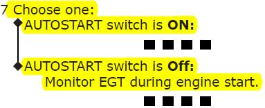
4 Normal Procedures Preflight procedures First Officer AUTO IGNITION selector - 1 or 2 AUTO IGNITION selector - SINGLE AUTO START switch (if installed) - ON
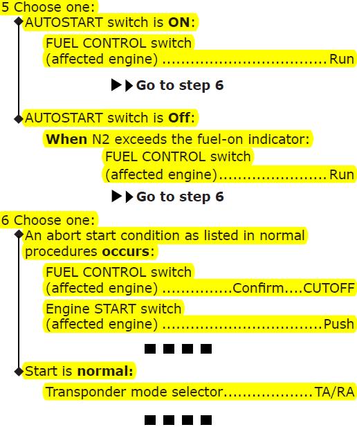
5 Normal Procedures Engine Start Procedure Engine Start Procedure Select the secondary engine indications. F/O Pack control selectors... SET F/O Set two or three packs off.. Start sequence... Announce C Call START ENGINE. C Engine START switch... Pull F/O Verify that the N2 RPM increases. F/O Verify that the oil pressure increases. C, F/O At maximum motoring (N2 greater than or equal to the fuel-on indicator and no increase for five to ten seconds) and a minimum of the fuel-on indicator: FUEL CONTROL switch...run C Verify that the EGT increases and stays below the EGT limit C, F/O After the engine is stabilized at idle, start the other engines. Do the ABORTED ENGINE START checklist for one or more of the following abort start conditions: the EGT does not increase by 20 seconds after the fuel control switch is moved to RUN there is no N1 rotation by 40% N2 the EGT quickly nears or exceeds the start limit the N2 is not at idle by 2 minutes after the fuel control switch is moved to RUN the oil pressure indication is not normal by the time the engine is stabilized at idle
6 Auto Start Procedure Normal Procedures Engine Start Procedure (Auto Start) Select the secondary engine indications. F/O Pack control selectors... SET F/O Set two or three packs off. To start two engines at the same time, it may be necessary to set three packs off. Start sequence... Announce C Call START ENGINE. C Engine START switch... Pull F/O FUEL CONTROL switch...run C Verify that the oil pressure increases. C, F/O Verify that there is N1 rotation and an oil pressure indication by idle N2. C, F/O After the engine is stabilized at idle, start the other engines. Autostart does corrective steps for: no EGT rise a hot start a hung start Do the ABORTED ENGINE START checklist for one or more of the following abort start conditions: there is no N1 rotation by idle N2 the fuel control switch is in RUN, the engine RPM is low, and the Autostart switch is off the oil pressure indication is not normal by the time the engine is stabilized at idle
7 Normal Procedures Before Takeoff Procedure Before Takeoff Procedure When responding to the FLAPS challenge in the BEFORE TAKEOFF CHECKLIST, the PF is verifying that the CDU and EICAS flap selections agree with the takeoff performance calculated. Engine warm up requirements: engine oil temperature must be above the lower amber band before takeoff Engine warm up recommendations (there is no need to delay the takeoff for these recommendations): when the engines have been shut down more than 2 hours: run the engines for 5 minutes when the taxi time is expected to be less than 5 minutes, start the engines as early as feasible use a thrust setting normally used for taxi operations Engine warm up requirements: engine oil temperature must be above the bottom of the temperature scale Engine warm up recommendations: run the engines for at least 3 minutes use a thrust setting normally used for taxi operations
8 Normal Procedures Takeoff Procedure Advance the thrust levers to approximately 1.10 EPR. Allow the engines to stabilize. Advance the thrust levers to approximately 70% N1. Allow the engines to stabilize. Procedure also applies to Supplemental Procedure Low Gross Wt, Aft CG Takeoff
9 Normal Procedures After Landing Procedure Engine cool down requirement: run the engines for at least 90 seconds use a thrust setting no higher than that normally used for taxi operations Engine cool down recommendations: run the engines for at least 5 minutes use a thrust setting no higher than that normally used for taxi operations Engine cool down recommendations: run the engines for at least 3 minutes use a thrust setting normally used for taxi operations
10 Supplementary Procedures Weather Radar Test Weather Radar Mode selector...non-test mode ND Mode selector...map EFIS WXR switch...push Note: In the short time the weather radar is on and not in the TEST position, it will radiate. Weather Radar Mode selector...test Observe the following sequence (approximately 20 seconds). The amber WINDSHEAR annunciation shows on the NDs and the aural message monitor radar display sounds. Then the amber WINDSHEAR annunciation blanks, the Master Warning lights illuminate, and the WINDSHEAR SYS and WINDSHEAR PRED EICAS messages show. Then the red WINDSHEAR annunciation shows on the NDs, the WINDSHEAR SYS and WINDSHEAR PRED EICAS messages blank, the Master Warning lights extinguish, and the aural messages go around, windshear ahead, and then windshear ahead, windshear ahead sound. During this time, the rainbow test pattern (with embedded PWS symbol) is shown. Continue
11 Supplementary Procedures Weather Radar Test Weather Radar Mode selector...test ND Mode selector... MAP EFIS WXR switch... Push Verify radar test pattern displays on ND. EFIS WXR switch... Push Select Captain s and First Officer s weather radar displays off. Weather Radar Mode selector... As desired
 - TR APU selector START, then ON Position APU selector back to ON position. Do not allow APU selector to spring back to ON position.")
12 Supplementary Procedures Electrical Power up Electrical Power Up The following procedure is accomplished to permit safe application of electrical power. If APU power desired: APU Start Source switch (if installed) - TR APU selector START, then ON Position APU selector back to ON position. Do not allow APU selector to spring back to ON position. APU generator 1 and APU generator 2 AVAIL lights - Illuminated APU GENERATOR 1 switch - Push Verify ON light illuminated. APU GENERATOR 2 switch - Push
13 Supplementary Procedures Engine Start Procedure Manual Start Engine Start Procedure - Manual Start Select the secondary engine indications. F/O Pack control selectors...set F/O All packs may be off or one pack may be on for engine start. Start sequence...announce C AUTOSTART switch...off F/O Call START ENGINE C Engine START switch...pull F/O Verify that the N2 RPM increases. F/O Verify that the oil pressure increases. C, F/O At the fuel-on indicator: FUEL CONTROL switch...run C Verify that the EGT increases and stays below EGT limit. C, F/O After the engine is stable at idle: If autostart is operative: AUTOSTART switch... ON F/O The autostart switch may stay OFF between manual starts when more than one engine is to be started manually. After the engine is stabilized at idle, start the other engines. Do the ABORTED ENGINE START checklist for one or more of the following abort start conditions: the EGT does not increase by 25 seconds after the fuel control switch is moved to RUN there is no N1 rotation by idle N2 the EGT quickly nears or exceeds the start limit N2 does not stabilize at idle the oil pressure indication is not normal by the time the engine is stabilized at idle
14 Supplementary Procedures Cold Weather Operations Taxi - Out CAUTION: Taxi at a reduced speed. Use smaller tiller and rudder inputs, and apply minimum thrust evenly and smoothly. Taxiing on slippery taxiways or runways at excessive speed or with high crosswinds may start a skid. When nacelle anti-ice is required and the OAT is 3 C or below, do an engine run up, as needed, to minimize ice build-up. Use the following procedure:.c Check that the area behind the airplane is clear. Run-up to a minimum of 50% N1 for approximately 1 second duration at intervals no greater than 15 minutes. Run-up to a minimum of 60% N1 for approximately 30 seconds duration at intervals no greater than 30 minutes. This procedure and parameters also apply to SP - After Landing Procedure
15 Supplementary Procedures Cold Weather Operations Takeoff Procedure Do the normal Takeoff Procedure with the following modifications. When nacelle anti-ice is required and the OAT is 3 C or below, the takeoff must be preceded by a static engine run-up. Use the following procedure: Run-up to a minimum of 50% N1 and confirm stable engine operation before the start of the takeoff roll. Run-up to a minimum of 60% N1 for approximately 30 seconds duration and confirm stable engine operation before the start of the takeoff roll.
16 Supplementary Procedures Cold Weather Operations Nacelle Anti-ice Operation In flight Nacelle anti-ice must be ON during all flight operations when icing conditions exist or are anticipated, except when the temperature is below 40 C SAT. Prior to reducing thrust for descent in visible moisture and TAT less than 10 C, including SAT less than -40 C, nacelle anti-ice switch must be in the ON position. At or below 22,000 ft, wing anti-ice selector must be in the ON position. When these icing conditions (visible moisture and TAT less than 10 C, including SAT less than -40 C) are no longer present or anticipated, place the nacelle and wing anti-ice selectors in the OFF (or AUTO) position.
17 Supplementary Procedures Cold Weather Operations Fan Ice Removal Fan Ice Removal CAUTION: Avoid prolonged operation in moderate to severe icing conditions. If moderate to severe icing conditions are encountered: During flight in moderate to severe icing conditions for prolonged periods with N1 settings at or below 70%, or when fan icing is suspected due to high engine vibration, the fan blades must be cleared of any ice. Do the following procedure every 10 minutes on all engines, one engine at a time: increase thrust to a minimum of 70% N1 for 10 to 30 seconds.
18 Limitations Weight Limitations Weights Pounds Maximum Taxi Weight 878,000 Maximum Takeoff Weight 875,000 Maximum Fuel Transfer Weight 740,000 Maximum Landing Weight 652,000 Maximum Zero Fuel Weight 610,000 Minimum Flight Weight 377,400 Note: Maximum Fuel Transfer Weight is the weight above which Reserve Tanks 2 and 3 must be full. Note: In order to be above the a/c minimum flight weight, a minimum payload or fuel ballast of 20,000 lbs should be loaded. Additional weight limitations have been added to the above table. These limitations apply to and


19 Airplane General, Emergency Equipment, Doors, Windows Oxygen Mask Panel - Test and Reset switch is a push button type O2 flow indicator located in the top left corner of panel Test and Reset switch is a slide type O2 flow indicator located in the top right corner of panel
20 Air Systems Shoulder Air Selector 1. Rotate Sets air flow to side window shoulder air outlet


21 Anti-Ice, Rain Nacelle and Wing Anti-Ice Panel Push Button Switches installed Off Valve Closed On remains the same 3 Position Toggle switches installed Off - nacelle anti-ice valves commanded closed On remains the same Auto - In flight, nacelle anti-ice operates in response to inputs from the ice detection system. Requirements for valve operation are the same as ON position. On the ground, system off. When nacelle anti-ice valve is open at touchdown, valve remains open until engine shutdown. continue
22 Anti-Ice, Rain Automatic Ice Detection System Ice Detection System The automatic ice detection system detects airplane icing in flight. An ice detection system probe on the forward fuselage detects airplane icing in flight. The system provides data for displaying EICAS alert messages. Nacelle Anti-Ice System The nacelle anti-ice system uses engine bleed air to provide engine cowl inlet ice protection. Nacelle anti-ice can be operated in flight or on the ground. The nacelle anti-ice indication NAI is displayed beside the EICAS N1 indication when the nacelle anti-ice valve is open. When the Nacelle Anti-Ice switch is ON the selected engine igniters operate continuously. Nacelle Anti-Ice System Operation When the Nacelle Anti-Ice switch is ON, bleed air opens the nacelle anti-ice valve and bleed air is supplied to the engine inlet cowl. Automatic Ice Detection System The automatic ice detection system detects airplane icing in flight. The system consists of two ice detector probes on the forward fuselage. The system provides signals to control the nacelle and wing anti ice systems when those systems are in automatic mode. Nacelle Anti Ice System Nacelle Anti Ice System Automatic Operation In flight, when the NACELLEANTI-ICE switch is in AUTO, nacelle anti ice system operation is automatic. When ice is detected, bleed air opens the nacelle anti ice valve and bleed air is supplied to the engine cowl inlet. When ice is no longer detected, the nacelle anti ice valve closes and bleed air is no longer supplied to the engine inlet cowl. Nacelle Anti Ice System Manual Operation On the ground and in flight, when the NACELLEANTI-ICE switch is ON, bleed air opens the nacelle anti-ice valve and bleed air is supplied to the engine inlet cowl.

23 Communications Glareshield Microphone Switch N469SA 1. Push allows oxygen mask or boom microphone transmission on selected transmitter.
24 Communications Captain Audio System Switch 1. CAPT AUDIO SYSTEM Switch Normal (NORM) - all communication systems operate normally. VHF-L DIRECT - bypasses audio system by connecting Captain s boom/mic headset and control wheel push-to-talk switches directly to VHF-L transceiver. Allows Captain to communicate on VHF-L transceiver if audio system failure causes loss of communication. Volume control is not available.
 test in progress, or paper jam 3.")
25 Communications Printer Controls Appearance and switch functions Continue 1. FAIL Light Illuminated (amber) printer failure, or test in progress 2.PAPER Light Illuminated (amber) test in progress, or paper jam 3. RESET Switch Push aborts current print job deletes pending print job(s) resets printer Illuminated (white) reset in progress, or\ test in progress 4. TEST Switch Push tests printer prints test pattern Illuminated (white) - test in progress. 5. SLEW Switch Push and hold advances paper.

26 Communications Printer Controls Appearance and switch functions 1. SLEW Switch Push and hold - advances paper. 2. RESET Switch Push - resets Message (MSG) light. 3. TEST Switch Push tests printer when pushed with RESET switch, prints test pattern. 4. PAPER Indicator Indicates amount of paper in printer. 5. FAIL Light Illuminated (amber) - indicates printer failure. 6. PAPER Light Illuminated (amber) - indicates printer out of paper. 7. Message (MSG) Light Illuminated (blue) - indicates message sent to printer.
27 Communications Stuck Mic Protection Stuck Mic Protection On the ground, any VHF radio transmitting for longer than 35 seconds is disabled following annunciation of a warning beep. The radio is enabled when the microphone switch for that radio is released. On the ground or in flight, an EICAS advisory message RADIO TRANSMIT will display if any VHF or HF transceiver has been keyed for more than 30 seconds.
28 Electrical Alternate EFIS Selector ALTERNATE EFIS Selector CAPT - left FMC, and left PFD and ND powered by APU alternate power if captain transfer bus unpowered. right PFD and ND unpowered if both transfer busses unpowered. F/O - left FMC and first officer PFD and ND powered by APU alternate power if first officer transfer bus is unpowered. Left PFD and ND unpowered if both transfer busses unpowered. Note: Selector not functional during normal electrical system operation, or with failure of only captain transfer bus.


29 Electrical Electrical Power System Schematic Note: does not have the alternate EFIS switch

30 Engines, APU Primary Engine Display Primary Engine Indications Displayed full time on EICAS display: EPR N1 EGT 1. Primary Engine Indications Displayed full time on EICAS display: N1 EGT The N1 indication does not change color when the maximum N1 is reached
 - maximum allowable thrust. Displayed (white) - maximum EPR is invalid.")
31 Engines, APU EPR/N1 Indications Thrust Reverser Indication Displayed REV (amber) - reverser in transit. Displayed REV (green) - reverser fully deployed. EPR Digital EPR displayed (white). Maximum EPR Line Displayed (amber) - maximum allowable thrust. Displayed (white) - maximum EPR is invalid. EPR Indication EPR, displayed: (white) - normal operating range (red) - operating limit reached Reference EPR Displayed (digital, green) - reference thrust selected by FMC. Primary Engine Indications Displayed full time on EICAS display: N1 EGT PW - The EEC selects an unannunciated alternate mode when reverse thrust is used due to EPR sensing inaccuracies during reverser operation.
 and a minimum of the fuel-on indicator: FUEL CONTROL switch...run")
32 Engines, APU N2 Indication At maximum motoring (N2 greater than or equal to the fuel-on indicator and no increase for five to ten seconds) and a minimum of the fuel-on indicator: FUEL CONTROL switch...run N469SA At the fuel-on indicator: FUEL CONTROL switch...run
 oil")
33 Engines, APU Oil Pressure Indications 4. Oil Pressure Amber Band - GE only Displayed (amber) oil pressure caution range.
34 Engines, APU Engine Vibration Indications Engine Vibration Source Identifies the vibration source being displayed. Displayed (white) - vibration source with the highest vibration: N1 - N1 rotor vibration N2 - N2 rotor vibration Engine Vibration Source Identifies the vibration source being displayed. Displayed (white) vibration source with the highest vibration: FAN - fan vibration LPT - N1 Low Pressure Turbine vibration N2 - N2 rotor vibration
 N1 EGT Compact Engine Indications Displayed continuously: N1")
35 Engines, APU Compact Engine Display Compact Engine Indications Displayed continuously: EPR (Only for P&W Engines) N1 EGT Compact Engine Indications Displayed continuously: N1 EGT

36 Engines, APU Engine Start Panel AUTO IGNITION Selector 1, BOTH, or 2 - selects respective igniters. Selected igniters operate when any of the following occur: during start when N2 RPM less than 50% trailing edge flaps out of up position nacelle anti-ice ON Engine START Switches Pull (Autostart switch ON) arms start valve opens engine bleed air valve Pull (Autostart switch OFF) Same as P&W AUTO IGNITION Selector SINGLE - EEC alternates igniter 1 and igniter 2 after every second ground start EEC selects both igniters for in-flight start or flameout Selected igniters operate when any of the following occur: engine flameout AUTOSTART Switch ON arms the autostart system. OFF autostart system is disabled start is manually controlled

37 Engines, APU Engine Fuel System Schematic PW- The first stage engine fuel pump adds additional pressure to the fuel. GE- The first and second stage engine fuel pumps add additional pressure to the fuel.


38 Engines, APU Engine Oil system P&W The oil is cooled first by fan air as it flows through the air/oil heat exchanger and then by fuel as it flows through the fuel/oil heat exchanger. GE - The oil is cooled by fuel as it flows through the fuel/oil heat exchanger.
39 Engines, APU Thrust Reverser System PW- Each engine has a hydraulically actuated fan air thrust reverser. GE- Each engine has a pneumatically actuated fan air thrust reverser.
40 Engines, APU APU Operation APU Start An APU start requires both the main and APU batteries. The APU battery supplies power to the starter, air inlet door, APU controller, DC fuel pump, and APU fire detection system. The main battery supplies power for the APU fire extinguisher, APU fuel valve, and standby power for the APU controller. All APU components except the starter are powered by the main battery while the APU starter is engaged during a start sequence. Rotating the APU selector momentarily to START begins the start sequence. The APU fuel valve and inlet door open simultaneously. Starter engagement occurs when the inlet door is fully open. The start sequence continues with ignition, lightoff, and engine acceleration to rated speed. Between starts Battery wait: 1 and 2 1 minute 2 and 3 5 minutes 3 and 4 1 minute 4 and 5 20 minutes 5 and 6 1 minute For additional starts, wait 20 minutes then alternate between one and 20 minutes for further starts. continue APU Start limitations are not the same for P&W and GE Engines.
41 Engines, APU APU Operation Cont. APU Start The APU DC electric starter is powered by an APU start transformer rectifier (TR) whenever galley bus 2 is powered. Galley bus 2 may be powered from either an external or internal AC power source through the synchronous bus. If galley bus 2 is not powered, starter power is supplied by the 24 volt APU battery. The battery has a charger which disconnects during APU starter engagement. The APU battery powers the inlet door, APU controller, DC fuel pump, and APU fire detection system. The main battery supplies power for the APU fire extinguisher, APU fuel valve, and standby power for the APU controller. During a battery start sequence, the APU starter is powered by the APU battery and all APU components except the starter are powered by the main battery while the APU starter is engaged. Rotating the APU selector momentarily to START begins the start sequence. The APU fuel valve and inlet door open simultaneously. Starter engagement occurs when the inlet door is fully open. The start sequence continues with ignition, lightoff, and engine acceleration to rated speed. Between starts TR wait: Battery wait: 1 and 2 1 minute 1 minute 2 and 3 10 minutes 5 minutes 3 and 4 20 minutes 1 minute 4 and 5 20 minutes 20 minutes 5 and 6 20 minutes 1 minute For additional starts with TR power, wait 20 minutes between each start. For additional starts with battery power, wait 20 minutes then alternate between one and 20 minutes for further starts. APU Start limitations are not the same for P&W and GE Engines.

42 Flight Instrument, Displays Instrument Source Select Panels PVD is only installed on and is Deactivated Continued
 - Deactivated 2.")
43 Flight Instrument, Displays Para-Visual Display The PVD will be Deactivated 1. Para-Visual Display (PVD) - Deactivated 2. PVD Switch - Deactivated

44 Flight Instruments, Displays Radio Magnetic Indicator Radio magnetic indicator displays heading and VOR and ADF bearing to the selected station. Heading information is provided by the right or center IRU as selected by the F/O IRS source selector. Only installed on

 Appearance and")
45 Flight Management, Navigation Transponder Panel Above/Below switch () Appearance and functionality
 * has a")

46 Flight Management, Navigation Weather Radar Panel Appearance and functionality () * has a left and right tilt map and gain knob * Push button selections for TFR, WX, WS+T, MAP, and GCS, LR/T RR/T

47 Flight Management, Navigation Thrust Management Thrust limits are expressed as EPR limits. Thrust equalization references EPR. Thrust limits are expressed as N1 limits. Thrust equalization references N1.
 - loss of antiskid protection to related wheels.")
48 Landing Gear Gear Synoptic Display Disabled System Messages TILT (amber) - main gear truck not in full tilt positions. ANTISKID (white or amber) - loss of antiskid protection to related wheels. LIMITER (white or amber) - torque limiting control fault detected.
 - predictive WINDSHEAR AHEAD alert or immediate WINDSHEAR alert is occurring all other GPWS alerts inhibited Alert on PFD PULL UP (red) GPWS PULL UP alert is occurring.")
49 Warning Systems GPWS and PWS Alerts on PFD Alert on PFD PULL UP (red) - PULL UP alert is occurring. WINDSHEAR (red) - predictive WINDSHEAR AHEAD alert or immediate WINDSHEAR alert is occurring all other GPWS alerts inhibited Alert on PFD PULL UP (red) GPWS PULL UP alert is occurring. WINDSHEAR (red) WINDSHEAR alert is occurring all other GPWS alerts inhibited Continue
 Symbol, radials, and weather radar returns displayed automatically when: PWS alert occurs, and WXR is not selected on either ND, and respective ND is in MAP, MAP CTR,")
50 Warning Systems Predictive Windshear (PWS) Display and Annunciations Only installed on PWS Symbol Displayed (red and black) - PWS alert is occurring displays windshear location and approximate geometric size (width and depth) Symbol, radials, and weather radar returns displayed automatically when: PWS alert occurs, and WXR is not selected on either ND, and respective ND is in MAP, MAP CTR, VOR, or APP mode When terrain display is selected and PWS alert occurs, weather radar display replaces terrain display. PWS Radials Displayed (amber) - PWS alert is occurring Extend from PWS symbol to help locate windshear event WINDSHEAR Annunciation WINDSHEAR (amber) - PWS caution is occurring. WINDSHEAR (red) - PWS warning is occurring. Displayed in all navigation display modes.

51 Warning Systems Master WARNING/CAUTION Reset Switches and Lights Master WARNING/CAUTION Reset Switch Push extinguishes master WARNING lights extinguishes master CAUTION lights silences the aural alert that accompany the EICAS warning messages: CABIN ALTITUDE CONFIG GEAR, if displayed because landing gear not down and locked, any thrust lever at idle, and radio altitude less than 800 feet FIRE PILOT RESPONSE OVERSPEED


52 Warning Systems Transponder Mode Selector TCAS Airspace Switch ABOVE - displays altitude reporting traffic from 2,700 feet below to 9,000 feet above current altitude. Normal (NORM) - displays altitude reporting traffic from 2,700 feet below to 2,700 feet above current altitude. BELOW - displays altitude reporting traffic 9,000 feet below to 2,700 feet above current altitude.

53 Warning Systems Radio Altitude/Barometric Altitude Control N469SA The airplanes listed in the table below are covered in this manual. The numbers distinguish data peculiar to one or more, but not all of the airplanes. Where data applies to all airplanes listed, no reference is made to individual airplane numbers. Minimums Voice Annunciation GPWS provides the voice annunciation MINIMUMS at the altitude set by the captain RADIO/BARO Altitude control on the EFIS control panel. Altitude Voice Annunciations During Approach GPWS provides the following altitude voice annunciations during approach: 2,500 feet - TWENTY-FIVE HUNDRED 1,000 feet - ONE THOUSAND 500 feet - FIVE HUNDRED 100 feet - ONE HUNDRED 50 feet - FIFTY 40 feet - FORTY 30 feet - THIRTY 20 feet - TWENTY 10 feet - TEN 5 feet - FIVE GPWS provides the voice annunciations PLUS HUNDRED at 100 feet above the altitude set by the Captain s RADIO/BARO Altitude control on the EFIS control panel, and MINIMUMS at the altitude set.

54 QUICK REFERENCE HANDBOOK Differences
55 Preface Airplane Effectivities Effectivities will be displayed below associated checklist title ALL QRH DIFFERENCES ARE HIGHLIGHTED IN YELLOW DOOR F/D OVHD When airplane effectivities are stated immediately below a checklist title, the entire checklist applies to the listed airplanes only. In the following example, the ENG 1, 2, 3, 4 FAIL checklist is applicable to only:
56 DOOR F/D OVHD Condition: The flight deck overhead door is not closed and secure.
57 >ELT ON Condition: The emergency locator transmitter is on.

58 BLD 1, 2, 3, 4 OVHT/PRV BLD 1, 2, 3, 4 OVHT/PRV Condition: One or more of these occur: An engine bleed air overheat A PRV is failed closed Condition: One or more of these occur: An engine bleed air overheat A PRV is failed closed Objective: To turn the engine bleed switch off while at a high power setting.
59 >ANTI-ICE >ANTI-ICE Condition: All of these occur: A nacelle or wing anti-ice system is on TAT above 12 C Ice is not detected Condition: All of these occur: A nacelle or wing anti-ice system is on TAT above 12 C
60 >ANTI-ICE NAC Condition: All of these occur: A nacelle anti-ice system is on TAT above 12 C Ice is not detected
61 >ANTI-ICE WING Condition: All of these occur: A wing anti-ice system is on TAT above 12 C Ice is not detected
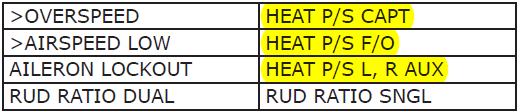
62 HEAT P/S CAPT, F/O HEAT P/S CAPT, F/O Condition: A pitot static probe heat is failed. Objective: To isolate the failed probe to prevent erroneous flight instrument indications. Condition: A pitot static probe heat is failed.
63 HEAT P/S L, R AUX HEAT P/S L, R AUX Condition: A pitot static probe heat is failed. Objective: To isolate the failed probe to prevent erroneous flight instrument indications. Condition: A pitot static probe heat is failed.
64 >ICING Condition: Ice detector detects ice. 1 Message can be cancelled but cannot be recalled.
65 >ICE DETECTORS Condition: The ice detectors are failed.
66 >ICING NAC Condition: Ice is detected and a nacelle anti-ice system is off.
67 >ICING WING Condition: Ice is detected and the wing anti-ice system is off.
68 >NO ICING Condition: Ice no longer detected. 1 Message can be cancelled but cannot be recalled. If ice detected, message no longer shown.
69 >RADIO TRANSMIT Condition: A VHF or HF radio transmits for 30 seconds or more.
70 RADIO TRANSMIT Condition: A radio transmits continuously without crew input. Objective: To identify and isolate the stuck microphone. 1 Transmitter select switches (all audio select panels)... Flight Interphone This deselects the radios and stops radio transmissions. 2 The microphone or interphone with the stuck switch continuously transmits on flight interphone. 3 The associated audio select panel should stay on flight interphone. All other audio select panels may be used normally.
71 Radio Transmit Continuous (Stuck Microphone Switch) Condition: A radio transmits continuously without crew input. Objective: To identify and isolate the stuck microphone. 1 Transmitter select switches (all audio select panels)... Flight Interphone This deselects the radios and stops radio transmissions. 2 The microphone or interphone with the stuck switch continuously transmits on flight interphone. 3 The associated audio select panel should stay on flight interphone. All other audio select panels may be used normally.

72 ELEC AC BUS 1, 2, 3, ELEC AC BUS 1, 2, 3,
73 >STBY BUS APU Condition: The APU standby bus is not powered.
74 >STBY BUS MAIN Condition: The main standby bus is not powered.
75 >STBY POWER OFF Condition: The standby bus is not powered.
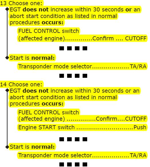
76 Aborted Engine Start Aborted Engine Start When N2 decreases below 20%: Engine START switch (affected engine)... Pull Motor the engine for 30 seconds. Engine START switch (affected engine)...push 3 When N2 decreases below 20%: AUTOSTART switch... Off This allows engine motoring. Engine START switch (affected engine)... Pull Motor the engine for 30 seconds. Engine START switch (affected engine)...push

77 ENG 1, 2, 3, 4 AUTOSTART
 or Multiple")

78 ENG 1, 2, 3, 4 FAIL (multiple) or Multiple Engine Flameout or Stall ENG 1, 2, 3, 4 FAIL (multiple) or Multiple Engine Flameout or Stall

79 Engine Limit or Surge or Stall Engine Limit or Surge or Stall
80 >AUTOSTART OFF Condition: The engine autostart switch is off.
81 >EEC 1, 2, 3, 4 TEST PWR Condition: EEC maintenance power switch in TEST.
82 ENG 1, 2, 3, 4 EEC MODE ENG 1, 2, 3, 4 EEC MODE Condition: An EEC is in the alternate control mode. Objective: To place all the EECs in alternate. Condition: An EEC is in the alternate control mode. Objective: To place all the EECs in alternate. 1 Do these steps on all operating engines, one 1 Do these steps on all operating engines, one engine at a time: engine at a time: Thrust lever...retard to mid position Thrust lever...retard to mid position ELEC ENG CONTROL switch... ALTN ELEC ENG CONTROL switch... ALTN 2 Maximum thrust limiting is not available. 2 Maximum thrust limiting is not available. 3 Autothrottle is not available. 3 Autothrottle is available.

83 ENG 1, 2, 3, 4 FAIL ENG 1, 2, 3, 4 FAIL
84 >ENG 1, 2, 3, 4 LIM PROT >ENG 1, 2, 3, 4 LIM PROT Condition: The EEC is in the alternate control mode and thrust is approaching maximum rating. Condition: The EEC is in the alternate mode and command N1 is more than the limit.

85 ENG 1, 2, 3, 4 OIL FILT ENG 1, 2, 3, 4 OIL FILT Condition: Oil filter contamination can cause oil to bypass the oil filter. 1 Primary engine oil filter approaching bypass condition. Oil flow to the engine will be filtered through the secondary filter element. Condition: Oil filter contamination can cause oil to bypass the oil filter.

86 ENG 1, 2, 3, 4 OIL TEMP ENG 1, 2, 3, 4 OIL TEMP
87 >ENG 1, 2, 3, 4 RPM LIM >ENG 1, 2, 3, 4 RPM LIM Condition: The N1 or N2 red line limit restricts the engine s thrust. Condition: The N2 red line limit restricts the engine s thrust.


88 Engine In-flight Start Engine In-flight Start

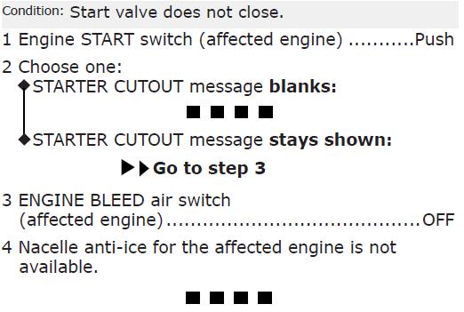
89 STARTER CUTOUT 1, 2, 3, STARTER CUTOUT 1, 2, 3,

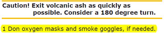


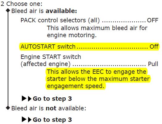
90 Volcanic Ash Volcanic Ash

91 Fire Engine Tailpipe Fire Engine Tailpipe


92 IAS DISAGREE or Airspeed Unreliable 10.1 IAS DISAGREE or Airspeed Unreliable 10.5
93 ALT DISAGREE ALT DISAGREE Entire Procedure differs from. Consult QRH Entire Procedure differs from. Consult QRH
94 >FMC RUNWAY DIS Condition: Airplane is not on the FMC origin runway when takeoff is attempted.

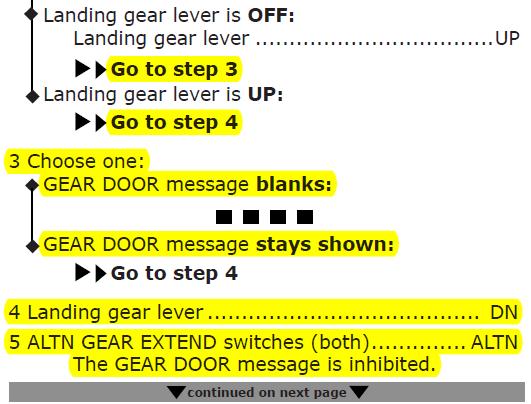
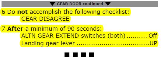
95 GEAR DOOR GEAR DOOR
96 >PILOT RESPONSE Condition: Pilot action is not detected during a specified time.
A310 MEMORY ITEMS Last Updated: 20th th October 2011
 A310 MEMORY ITEMS Last Updated: 20th th October 2011 1. Emergency Descent: Crew Oxygen Mask ON Crew Communication (Headsets) Establish Turn Initiate Descent Initiate o It is recommended to descend with
B737 NG Anti Ice & Rain
 B737 NG Anti Ice & Rain Introduction Thermal anti-icing (TAI), electrical anti-icing, and windshield wipers are the systems provided for ice and rain protection. The anti-ice and rain systems include:
Introduction. I. Introduction Abbreviations Icon Legend Resources
 Introduction Management Reference Guide I. Introduction Abbreviations Icon Legend Resources II. Takeoff Performance Computation Limitation Legend Corrections Maximum Takeoff Performance (Full Thrust Method)
OVERHEAD PANEL PROCEDURES FLASH CARDS
 OVERHEAD PANEL PROCEDURES FLASH CARDS Boeing 737-800 A supplement to the procedures and checklists publication, Flying the Boeing 737-800 NG Greg Whiley Aussie Star Flight Simulation ELECTRICAL POWER UP
HAB. B-777 AIRPLANE GENERAL, EMER EQUIP, DOORS, WINDOWS
 HAB. B-777 AIRPLANE GENERAL, EMER EQUIP, DOORS, WINDOWS 1 What must the aircrew do if using the portable halon fire extinguishers on the flight deck? A) All flight crew members must wear oxygen masks and
CHAPTER ICE AND RAIN PROTECTION SYSTEM
 15--00--1 ICE AND RAIN PROTECTION SYSTEM Table of Contents REV 3, May 03/05 CHAPTER 15 --- ICE AND RAIN PROTECTION SYSTEM Page TABLE OF CONTENTS 15-00 Table of Contents 15--00--1 INTRODUCTION 15-10 Introduction
EXAMEN POR MATERIAS PARA USO DE LOS POSTULANTES A LA HABILITACIÓN DE TIPO EN MATERIAL B733. ENERO 2018
 DEPARTAMENTO SEGURIDAD OPERACIONAL SUBDEPARTAMENTO LICENCIAS SECCIÓN EVALUACIONES EXAMEN POR MATERIAS PARA USO DE LOS POSTULANTES A LA HABILITACIÓN DE TIPO EN MATERIAL B733. ENERO 2018 Cantidad de Preguntas
B777. Electrical DO NOT USE FOR FLIGHT
 B777 Electrical DO NOT USE FOR FLIGHT 6.10 Electrical-Controls and Indicators Electrical Panel [IFE/PASS SEATS and CABIN/UTILITY switches basic with C/L 350] 1 2 IFE/PASS CABIN/ SEATS UTILITY 3 11 APU
Examen Teórico sobre Habilitación de Tipo B (Última actualización: Septiembre 2016)
") DIRECCIÓN GENERAL DE AERONÁUTICA CIVIL DEPARTAMENTO SEGURIDAD OPERACIONAL SUBDEPARTAMENTO LICENCIAS Examen Teórico sobre Habilitación de Tipo B-737-300 (Última actualización: Septiembre 2016) Materia:
DIRECCIÓN GENERAL DE AERONÁUTICA CIVIL DEPARTAMENTO SEGURIDAD OPERACIONAL SUBDEPARTAMENTO LICENCIAS Examen Teórico sobre Habilitación de Tipo B-737-300 (Última actualización: Septiembre 2016) Materia:
Cessna Citation XLS - Electrical
 GENERAL Electrical power for the Citation XLS comes primarily from DC sources originating with the starter/ generators, the Auxiliary Power Unit (APU) or the battery. A receptacle below the left engine
Canadair Regional Jet 100/200 - Auxiliary Power Unit
 1. INTRODUCTION The auxiliary power unit (APU) is installed within a fireproof titanium enclosure in the aft equipment compartment. The APU is a fully automated gas turbine power plant which drives an
ifly Jets: The 737NG Quick Reference Handbook Revision Number: 3 Revision Date: July 26, 2010
 ifly Jets: The 737NG ifly Jets: The 737NG Revision Number: 3 Revision Date: July 26, 2010 http://www.iflysimsoft.com/ The ifly Developer Team WARNING This manual is only used for understanding the functionalities
Bombardier Challenger Auxiliary Power Unit
 GENERAL A Honeywell 36 150(CL) constant-speed gas turbine auxiliary power unit (APU) is installed within a fire-resistant compartment in the aft equipment bay. The APU drives a generator, providing AC
AIRPLANE OPERATIONS MANUAL SECTION 2-15
 SECTION 2-15 TABLE OF CONTENTS Block General... 2-15-05..01 Bleed Air Thermal Anti-Icing System... 2-15-10..01 Wing, Stabilizer and Engine Anti-icing Valves Operational Logic... 2-15-10..04 EICAS Messages...
Takeoff Flaps UP 2000
 Takeoff Flaps UP 2000 30 60 75 80 85 V1 Gear UP Flap Position Indicator blanked 10 seconds after flaps UP Asymmetry Protection Near Zero Yaw Automatic unlock all surfaces (maintenance) Speedbrakes auto
1. Aircraft General (0 Hours 39 minutes) 2. Doors (0 Hours 33 minutes) 3. EFIS (2 Hours 55 minutes) 4. Exterior Lighting (0 Hours 24 minutes)
 2. Doors (0 Hours 33 minutes) 3. EFIS (2 Hours 55 minutes) 4. Exterior Lighting (0 Hours 24 minutes)") Course: CRJ900 (Pilot) Delivery Formats: Web Based or Portable Classroom Number of modules: 26 Estimated Course Time: 36 Hours 16 minutes The following topics are included in this CRJ900 (Pilot) CBT/WBT
Course: CRJ900 (Pilot) Delivery Formats: Web Based or Portable Classroom Number of modules: 26 Estimated Course Time: 36 Hours 16 minutes The following topics are included in this CRJ900 (Pilot) CBT/WBT
Cessna Citation XLS - Anti-Ice & De-Ice Systems
 GENERAL The airplane utilizes a combination of engine bleed air, electrical heating elements and pneumatic boots to accomplish anti-ice/deice functions. The anti-ice system consists of bleed air heated
POWER ON CHECK LIST COCKPIT PREPARATION
 Normal Check List DASH 8-402 1 POWER ON CHECK LIST CIRCUIT BREAKERS... CHECKED BATTERY MASTER... ON BATTERIES... ON MAIN BUS TIE... TIED EXTERNAL POWER... AS REQUIRED APU... AS REQUIRED BATTERIES & BATTERY
INDEX. Preflight Inspection Pages 2-4. Start Up.. Page 5. Take Off. Page 6. Approach to Landing. Pages 7-8. Emergency Procedures..
 INDEX Preflight Inspection Pages 2-4 Start Up.. Page 5 Take Off. Page 6 Approach to Landing. Pages 7-8 Emergency Procedures.. Page 9 Engine Failure Pages 10-13 Propeller Governor Failure Page 14 Fire.
Landing Gear & Brakes
 EMBRAER 135/145 Landing Gear & Brakes GENERAL The EMB-145 landing gear incorporates braking and steering capabilities. The extension/retraction, steering and braking functions are hydraulically assisted,
BEFORE START AFTER START
 BEFORE START ENGINE START AFTER START - Version 03 1.a. BEFORE START LOADSHEET...CHECK TAKEOFF DATA..... ENTER/REVISE TAKEOFF DATA... XCHECK COCKPIT DOOR...CLOSED SEAT BELTS ADJUST MCDU...PERF TO SEAT
MAJESTIC Q400 SHARED COCKPIT FLOWS CHECKLISTS MULTIPLAYER OPERATIONS.
 PRE LOAD IN Agree on Ports, Share IP and select who will be doing W&B. INITIAL LOAD IN On 1 System transfer Weight and Balance to Simulator Pause Simulation Save Flight as normal FSX Flight Transfer Save
AIRPLANE GENERAL Exterior REV 3, May 03/05
 Vol. 1 01--20--1 AIRPLANE GENERAL Exterior REV 3, May 03/05 24 ft 1 in (7.34 m) 5ft1in(1.55m) 10 ft 7 in (3.23 m) 6ft4in (1.93 m) 81 ft 6 in (24.85 m) 9ft6in(2.89m) 8ft10in (2.69 m) 36 ft 4 in (11.07 m)
by Greg Whiley Aussie Star Flight Simulation
 Flying the BAe 146 200/300 Version 2 by Greg Whiley Aussie Star Flight Simulation INTENTIALLY LEFT BLANK Greg Whiley Aussie Star Flight Simulation 2 Version Date Revision Version 1.0 25 June 2014 Original
DASSAULT AVIATION Proprietary Data
 F900EX EASY 02-30-00 CODDE 1 PAGE 1 / 2 TABLE OF CONTENTS 02-30 02-30-00 TABLE OF CONTENTS 02-30-05 GENERAL Introduction Anti-icing protection sources Anti-ice system location overview 02-30-10 DESCRIPTION
ENGINE GROUND RUNNING
 B737 600/700/800/900 (CFM 56) ENGINE GROUND RUNNING Guide and Reference Sheets This publication is for TRAINING PURPOSES ONLY. This information is accurate at the time of completion. No update service
Introduction. APU Location
 B737 NG APU Introduction The auxiliary power unit (APU) is a self contained gas turbine engine installed within a fireproof compartment located in the tail of the airplane. The APU supplies bleed air for
canaaair chaiiencjer
 canaaair chaiiencjer AUXILIARY POWER UNIT (APU) TABLE OF CONTENTS Subject Page GENERAL APU CONTROL START SYSTEM SHUTDOWN I BLEED AIR SYSTEM OIL SYSTEM 1 1 3 5 5 7 Figure Number LIST OF ILLUSTRATIONS Title
Full Authority Digital Electronic Control (FADEC)
") Eng.10 Engines-Description and Operation General The aircraft is equipped with three GE CF6-80C2 engines or three P&W PW4460 or PW4462 engines. Each engine has dual rotors, a Low Pressure Compressor (LPC)
Eng.10 Engines-Description and Operation General The aircraft is equipped with three GE CF6-80C2 engines or three P&W PW4460 or PW4462 engines. Each engine has dual rotors, a Low Pressure Compressor (LPC)
ATA 49 AUXILIARY POWER UNIT
 F900EX EASY 02-49-00 CODDE 1 PAGE 1 / 2 TABLE OF CONTENTS 02-49 02-49-00 TABLE OF CONTENTS 02-49-05 GENERAL Introduction Sources APU location 02-49-10 DESCRIPTION Introduction Description Operating principle
SECTION III HYDRAULICS & LANDING GEAR
 TABLE OF CONTENTS Pilot s Manual SECTION III HYDRAULICS & LANDING GEAR Hydraulic System... 3-1 Firewall Shutoff Valves... 3-2 Source Selector Valve... 3-2 AUX HYD Pump Control... 3-2 Main/Auxiliary System
Central Warning Systems
 CIRRUS AIRPLANE MAINTENANCE MANUAL Central Warning Systems CHAPTER 31-50: CENTRAL WARNING SYSTEMS GENERAL 31-50: CENTRAL WARNING SYSTEMS 1. General This section describes the Indicating/Recording Systems
PA GURW (December 30, 2000) PRE-START. Langley Flying School. Airspeeds (MPH) for Safe Operation. Cockpit Checks
 PRE-START. Langley Flying School. Airspeeds (MPH) for Safe Operation. Cockpit Checks") Langley Flying School PA-34-200 GURW (December 30, 2000) Airspeeds (MPH) for Safe Operation V y (all weights) 105 V x (all weights) 90 En Route Climb 120 V mc 80 V yse 105 V xse 93 V r 80 V r (25 Flaps)
Langley Flying School PA-34-200 GURW (December 30, 2000) Airspeeds (MPH) for Safe Operation V y (all weights) 105 V x (all weights) 90 En Route Climb 120 V mc 80 V yse 105 V xse 93 V r 80 V r (25 Flaps)
Fokker 50 - Ice & Rain Protection. Controls and indicators of the AIRFRAME DE-ICING system are located at the ice protection panel.
 ICE AND RAIN PROTECTION AIRFRAME DE-ICING Description Controls and indicators of the AIRFRAME DE-ICING system are located at the ice protection panel. Airframe de-icing is accomplished by alternately inflating
DASSAULT AVIATION Proprietary Data
 F2000EX EASY 02-49-00 CODDE 1 PAGE 1 / 2 TABLE OF CONTENTS 02-49 02-49-00 TABLE OF CONTENTS 02-49-05 GENERAL Introduction Sources Equipment location 02-49-10 DESCRIPTION Introduction Description Operating
DASSAULT AVIATION Proprietary Data
 F2000EX EASY 02-70-00 CODDE 1 PAGE 1 / 2 TABLE OF CONTENTS 02-70 02-70-00 TABLE OF CONTENTS 02-70-05 GENERAL Introduction Sources Engine location 02-70-10 DESCRIPTION Introduction Major components Operating
Vso 61. Vs1 63. Vr 70. Vx 76. Vxse 78. Vy 89. Vyse. 89 (blue line) Vmc. 61 (radial redline) Vsse 76. Va 134) Vno 163
 Vmc. 61 (radial redline) Vsse 76. Va 134) Vno 163") PA34-200T Piper Seneca II Normal procedures V-speeds Knots Vso 6 Vs 63 Vr 70 Vx 76 Vxse 78 Vy 89 Vyse Vmc 89 (blue line) 6 (radial redline) Vsse 76 Va 2-36(@4507lbs 34) Vno 63 Vfe 38 (0*)/2(25*)/07(40*)
PA34-200T Piper Seneca II Normal procedures V-speeds Knots Vso 6 Vs 63 Vr 70 Vx 76 Vxse 78 Vy 89 Vyse Vmc 89 (blue line) 6 (radial redline) Vsse 76 Va 2-36(@4507lbs 34) Vno 63 Vfe 38 (0*)/2(25*)/07(40*)
REFERENCE: 2861 wings 2044 trunk 4904 total BEW 10,655 BOW 11,185 Max Useful load 5115 MLanding ZFW FUEL BURNS 11min min min
 REFERENCE: 2861 wings 2044 trunk 4904 total BEW 10,655 BOW 11,185 Max Useful load 5115 MLanding 15700 ZFW 13000 FUEL BURNS 11min 357 27min 730 36 min 940 58min 1453 1:17 1800 2:20 2933 2:46 3283 3:00 3600
Jump to Table of Contents
 Jump to Table of Contents PIPER AIRCRAFT CORPORATION PA-28R-201, CHEROKEE ARROW III SECTION 3 EMERGENCY PROCEDURES 3.3 EMERGENCY PROCEDURES CHECK LIST ENGINE FIRE DURING
CESSNA SECTION 4. Unless otherwise noted, the following speeds are based on a maximum weight of 2550 pounds and may be used for any lesser weight.
 CESSNA SECTION 4 INTRODUCTION Section 4 provides procedures and amplified instructions for normal operations using standard equipment. Normal procedures associated with optional systems can be found in
Pilot's Operating Handbook Supplement AS-03
 POH / AFM SECTION 9 Pilot's Operating Handbook Supplement ASPEN EFD1000 PFD This supplement is applicable and must be inserted into Section 9 of the POH when the Aspen Avionics Evolution Flight Display
General. Airfoil Anti-Ice System
 General Ice.10 Ice and Rain Protection-Description and Operation Ice and rain protection consists of: Airfoil (wing and tail) anti-ice systems. Engine cowl anti-ice system. Air data heater system (pitot,
Dash8-200/300 - Auxiliary Power Unit APU CONTROLS AND INDICATORS. Page 1
 APU CONTROLS AND INDICATORS Page 1 APU control and indicators Page 2 closed APU controls and indicators Page 3 SYSTEM DESCRIPTION General The auxiliary power unit (APU) is a gas turbine engine, located
CHAPTER 6 ELECTRICAL SYSTEMS
 CHAPTER 6 ELECTRICAL SYSTEMS Page TABLE OF CONTENTS 06-00-01/02 DESCRIPTION General 06-10-01 Description 06-10-01 Controls and Indicators 06-10-02 COMPONENTS Circuit Breaker Panel Locations 06-20-01/02
CHAPTER 14 LANDING GEAR
 CHAPTER 14 LANDING GEAR Page TABLE OF CONTENTS 14-00-01/02 DESCRIPTION General 14-10-01 Description 14-10-01 Controls and Indicators 14-10-04 COMPONENTS Nose Gear 14-20-01 Main and Center Gear 14-20-02
CARENADO COPYRIGHTS. Normal & Emergency Checklist
 NORMAL PROCEDURES CHECKLIST PREFLIGHT CHECK Control wheel -- RELEASE BELTS Avionics -- OFF Master Switch -- ON Fuel quantity gauges -- CHECK Master switch -- OFF Ignition -- OFF Exterior -- CHECK FOR DAMAGE
CHECKLIST 1969 CESSNA 172-K. NOTE: Verify all information with airplane's POH
 CHECKLIST 1969 CESSNA 172-K NOTE: Verify all information with airplane's POH PRE-FLIGHT INSPECTION 1 CABIN 1 A.R.R.O.W. CHECK Airworthiness Cert. In Clear View Registration In Clear View Radio License
Embraer Systems Summary [Landing Gear & Brakes]
![Embraer Systems Summary [Landing Gear & Brakes]](/thumbs/87/96901154.jpg "Embraer Systems Summary [Landing Gear & Brakes]") GENERAL DESCRIPTION The airplane has two main landing gears and a single nose gear. Each main gear is a conventional two-wheeled landing gear. The nose gear is a conventional steerable two-wheeled unit.
GENERAL DESCRIPTION The airplane has two main landing gears and a single nose gear. Each main gear is a conventional two-wheeled landing gear. The nose gear is a conventional steerable two-wheeled unit.
Automatic Flight Chapter 4
 Automatic Flight Chapter 4 Table of Contents Section 0 4.0 Automatic Flight-Table of Contents Controls and Indicators................................ 4.10.1 Mode Control Panel (MCP).............................
General. APU Control System. APU Door System
 .10 -Description and Operation General The Auxiliary Power Unit () provides electrical and pneumatic power for engine start and air conditioning, and supplies ground and in-flight electrical power. Pneumatic
King Air B90. Speeds (KIAS)
") King Air B90 Speeds (KIAS) V MCA 92 V SSE (101) Derived from C90 V X 101 V Y 114 Down to 103 @ 30 000 V XSE 101 V YSE 110 Down to 101 @ 24 000 V A 169 V R 92 V 1 101 V MO 208 V FE 174 35% 130 100% V LE
King Air B90 Speeds (KIAS) V MCA 92 V SSE (101) Derived from C90 V X 101 V Y 114 Down to 103 @ 30 000 V XSE 101 V YSE 110 Down to 101 @ 24 000 V A 169 V R 92 V 1 101 V MO 208 V FE 174 35% 130 100% V LE
PA32-RT LANCE II CHECKLIST
 PA32-RT LANCE II CHECKLIST 6815.10.1112 1 Normal Procedures PREFLIGHT CHECK Control Wheel... RELEASE BELTS Parking brake... Set Master Switch... ON Fuel Quantity Gauges... check Master Switch... OFF Ignition...
EMBRAER 190. Powerplant DO NOT USE FOR FLIGHT
 EMBRAER 190 Powerplant DO NOT USE FOR FLIGHT Embraer 190 - Systems Summary [Powerplant] Two wing-mounted General Electric CF34-10E engines produce power to the EMBRAER 190. The General Electric CF34-10E
GIV MEMORY FLASH CARDS OCT09
 OCT09 GIV MEMORY FLASH CARDS Copyright 2009, FlightSafety International, Inc. Unauthorized reproduction or distribution is prohibited. All rights reserved. INSERT LATEST REVISED CARDS, DESTROY SUPERSEDED
CHAPTER 1 AIRCRAFT GENERAL
 CHAPTER 1 AIRCRAFT GENERAL INTRODUCTION This manual provides a description of the major airframe and engine systems in the Cessna Citation Mustang (Figure 1-1). This material does not supersede, nor is
PA , Model E Normal Checklist (04/15/11)
") PA-23-250, Model E Normal Checklist (04/15/11) Key Airspeeds IAS-MPH V NE 249 V NO 198 V LO/LE 150 V A (At max gross weight.) 149 Speed for single engine cruise. 138 V FE Quarter Flaps 160 Half Flaps 140
PA-23-250, Model E Normal Checklist (04/15/11) Key Airspeeds IAS-MPH V NE 249 V NO 198 V LO/LE 150 V A (At max gross weight.) 149 Speed for single engine cruise. 138 V FE Quarter Flaps 160 Half Flaps 140
CESSNA 182 CHECKLIST. LEFT WING Trailing Edge 1. Aileron CHECK freedom of movement and security
 CESSNA 182 CHECKLIST PRE-FLIGHT INSPECTION CABIN 1. Pilot s Operating Handbook AVAILABLE IN THE AIRPLANE (A.R.R.O.W.E) 2. Landing Gear Lever DOWN 3. Control Wheel Lock REMOVE 4. Ignition Switch OFF 5.
Section 5 - Ice & Rain Protection
 Section 5-5.1 Ice Detection 5.2 Ice Protection 5.2 Control 5.2 Operation 5.3 Engine Inlet 5.3 Pitot 5.4 Operation 5.4 Stall Warning Vane 5.4 Operation 5.4 Windshield 5.5 Windshield Anti-Ice Diagram - High
Piper Archer II (PA )
") 1. Oil... 6-8 qts, Cap Secure CABIN 1. POH & Documents.. Check Available 2. Magneto Switch...... OFF 3. Pitot/Static Drains... Push to Drain 4. Avionics/Electrical Switches... OFF 5. Master Switch. ON
1. Oil... 6-8 qts, Cap Secure CABIN 1. POH & Documents.. Check Available 2. Magneto Switch...... OFF 3. Pitot/Static Drains... Push to Drain 4. Avionics/Electrical Switches... OFF 5. Master Switch. ON
Cessna 172P PPL Checklist Page 1
 Cessna 172P PPL Checklist 06-08-2017 Page 1 Cessna 172P PPL Checklist 06-08-2017 Page 2 Checklist Items Informational Items Critical Memory Items PREFLIGHT COCKPIT CHECK (DO-LIST) Pitot Cover -- REMOVE
David s Flight Simulator Operations Manual
 DPW Solutions David s Flight Simulator Operations Manual Draft 0.2 David Woolterton Update 10/5/2016 Table of Contents Pre-Start Checklist... 2 Startup Checklist... 3 Before Taxi Checklist... 3 Taxi Checklist...
COLUMBIA 350 EMERGENCY PROCEDURES
 COLUMBIA 350 EMERGENCY PROCEDURES TABLE OF CONTENTS EMERGENCY PROCEDURES LANDING AND TAKEOFF Engine Failure During Takeoff...1 Engine Failure Immediately After Takeoff...1 Engine Failure During Climb to
Dash8 - Q400 - Pneumatics
 12.19.1 Introduction The Auxiliary Power Unit (APU) replaces the standard composite tailcone with a titanium tailcone and firewall. The APU is accessed by two clamshell type doors on the bottom of the
GENERAL The Honeywell model TFE731-40AR turbofan engine is a lightweight, two-spool, geared-stage, front-fan, jet engine.
 ENGINE GENERAL The Honeywell model TFE731-40AR turbofan engine is a lightweight, two-spool, geared-stage, front-fan, jet engine. The cross section of the engine is shown in Figure 7-71-1, page VII-71-3.
EMERGENCY PROCEDURES ENGINE FIRE DURING START/GROUND OPERATIONS STARTER ENERGIZED ANNUNCIATOR ILLUMINATED. Memory items are printed in red.
 ENG FIRE-GRND, STARTER ENERGIZED EMERGENCY PROCEDURES Memory items are printed in red. ENGINE FIRE DURING START/GROUND OPERATIONS 1. Mixture...IDLE CUTOFF 2. Fuel Selector Valve... OFF 3. Battery, Alternator,
NORMAL PROCEDURES. TABLE OF CONTENTS Page
 CESSNA SECTION 4 MODEL 208B 867 SHP NORMAL PROCEDURES NORMAL PROCEDURES TABLE OF CONTENTS Page Introduction............................................4-3 Airspeeds for Normal Operation............................4-4
Elmendorf Aero Club Aircraft Test
 DO NOT WRITE ON THIS TEST JAN 2014 Elmendorf Aero Club Aircraft Test SENECA II For the following questions, you will need to refer to the Pilots Information Manual for the PA-34-200T. USE ANSWER SHEET
BEFORE START AFTER START
 BEFORE START ENGINE START AFTER START A340 - Version 03b 1.a. BEFORE START LOADSHEET...CHECK TAKEOFF DATA..... ENTER/REVISE TAKEOFF DATA... XCHECK COCKPIT DOOR...CLOSED SEAT BELTS ADJUST MCDU...PERF TO
Bombardier Global Express - Hydraulics
 INTRODUCTION Hydraulic power is provided by three independent and isolated systems designated 1, 2 and 3 and operate at a nominal pressure of psi. SYSTEM 1 AND 2 Systems 1 and 2 are each powered by an
Interior Pre Flight Documents: Check Control Wheel Lock: Remove Flight Controls: Check Instruments: Check for Damage Switches: Verify All Off Master
 Interior Pre Flight Documents: Check Control Wheel Lock: Remove Flight Controls: Check Instruments: Check for Damage Switches: Verify All Off Master Switch ALT/BAT: On Fuel Gauge: Check Quantity Flaps:
8.- What illuminates the PACK OFF light? (FCOM, ) A.- High air flow. B.- Pack valve is closed. C.- ACM fan inoperative.
 A.- High air flow. B.- Pack valve is closed. C.- ACM fan inoperative.") DEPARTAMENTO SEGURIDAD OPERACIONAL SUBDEPARTAMENTO LICENCIAS Examen Teórico para Obtener o Renovar Habilitación de Tipo Boeing 767-300 (B763) (Última actualización: Agosto 2012) Materia Cantidad de Preguntas
DEPARTAMENTO SEGURIDAD OPERACIONAL SUBDEPARTAMENTO LICENCIAS Examen Teórico para Obtener o Renovar Habilitación de Tipo Boeing 767-300 (B763) (Última actualización: Agosto 2012) Materia Cantidad de Preguntas
DASSAULT AVIATION Proprietary Data
 FALCON 7X 02-70-05 CODDE 1 PAGE 1 / 6 GENERAL ACRONYMS LIST ACOC AGB APU A/T ATSV BOV CAS CB CL CMC CR DC DCU ECS EEC FADEC FBW FCU FF FOHE FSOV HP HPC HPT IGV ITT LP LPC LPT LRU MV N1 N2 PDU PLA PMA PMU
CHAPTER 7 ABNORMAL FLOWS AND CHECKLISTS TABLE OF CONTENTS
 CHAPTER 7 ABNORMAL FLOWS AND CHECKLISTS TABLE OF CONTENTS ELECTRICAL FAULTS...3 Alternator Failure / Low Voltage...3 INSTRUMENTS...7 Low vacuum indication / vacuum failure...7 Erroneous airspeed / altitude
At all times use approved company publications and aircraft manufacturer manuals as sole reference for procedures and data!
 Disclaimer These notes have not been approved by any aviation administration, by any airline nor by the aircraft manufacturer to whom it refers. At all times use approved company publications and aircraft
Aircraft Checklist Cessna 182T
 Aircraft Checklist Cessna 182T This is an abbreviated checklist. Most explanatory items, notes cautions and warnings have been omitted for brevity. Procedures in red/bold in this checklist should be committed
TECNAM P2004 BRAVO N128LS
 TECNAM P2004 BRAVO N128LS GENERAL INFORMATION NORMAL PROCEDURES TIME SENSITIVE EMERGENCY TECNAM P2004 BRAVO CHECKLIST [FLIGHT PLAN DESIGNATION IS BRAV ] EMERGENCY CONTACT The following are First Landings'
CHAPTER FUEL SYSTEM
 Vol. 1 13--00--1 FUEL SYSTEM Table of Contents REV 3, May 03/05 CHAPTER 13 --- FUEL SYSTEM Page TABLE OF CTENTS 13-00 Table of Contents 13--00--1 INTRODUCTI 13-10 Introduction 13--10--1 FUEL STORAGE 13-20
SECTION 2-13 FLIGHT CONTROLS
 SECTION 2-13 TABLE OF CONTENTS Block General... 2-13-05..01 Pitch Control... 2-13-10..01 General... 2-13-10..01 Elevator... 2-13-10..02 General... 2-13-10..02 Jammed Elevator... 2-13-10..02 Jammed Elevator
CHAPTER 4 ---AUXILIARY POWER UNIT
 Table of Contents Vol. 1 04--00--1 CHAPTER 4 ---AUXILIARY POWER UNIT Page TABLE OF CONTENT 04-00 Table of Contents 04--00--1 INTRODUCTION 04-10 Introduction 04--10--1 POWER PLANT 04-20 APU Power Plant
AIRCRAFT SYSTEMS PNEUMATIC
 Intentionally left blank PRELIMINARY PAGES - TABLE OF CONTENTS DSC-36-10 Description DSC-36-10-10 General GENERAL... A DSC-36-10-20 Engine Bleed System GENERAL... A Architecture... B Air Bleed Selection...C
DASSAULT AVIATION Proprietary Data
 F2000EX EASY 02-24-00 CODDE 1 PAGE 1 / 2 TABLE OF CONTENTS 02-24 02-24-00 TABLE OF CONTENTS 02-24-05 GENERAL Introduction Sources Equipment location 02-24-10 DESCRIPTION Generation Distribution Operation
SECTION 3 EMERGENCY PROCEDURES CONTENTS
 CONTENTS Page Definitions.................................. 3-1 Power Failure - General......................... 3-1 Power Failure Above 500 feet AGL................ 3-2 Power Failure Between 8 and 500
NORMAL PROCEDURRES CHECKLIST PA T SENECA II PREFLIGHT CHECK INSIDE CABIN OUTSIDE CABIN
 NORMAL PROCEDURRES CHECKLIST PA-34-200T SENECA II PREFLIGHT CHECK INSIDE CABIN Avionics Master Switch -- OFF Landing Gear Control. -- DOWN Mixture Controls -- IDLE/CUTOFF Ignition Switches -- OFF Master
canadair chzflleriqer OPERATING MANUAL PSP 601A-6 SECTION 5 AUXILIARY POWER UNIT (APU)
") OPERATING MANUAL. AUXILIARY POWER UNIT (APU) 1.. 3. 4. 5. 6. GENERAL APU CONTROL START SYSTEM SHUTDOWN BLEED AIR SYSTEM OIL SYSTEM TABLE OF CONTENTS Page 1 3 3 Figure Number LIST OF ILLUSTRATIONS Title
OPERATING MANUAL. AUXILIARY POWER UNIT (APU) 1.. 3. 4. 5. 6. GENERAL APU CONTROL START SYSTEM SHUTDOWN BLEED AIR SYSTEM OIL SYSTEM TABLE OF CONTENTS Page 1 3 3 Figure Number LIST OF ILLUSTRATIONS Title
SECTION 5 AUXILIARY POWER UNIT (APU) TABLE OF CONTENTS LIST OF ILLUSTRATIONS. Title
 TABLE OF CONTENTS LIST OF ILLUSTRATIONS. Title") BOMBARDIER AUXILIARY POWER UNIT (APU) TABLE OF CONTENTS Subject GENERAL APU CONTROL START SYSTEM SHUTDOWN BLEED AIR SYSTEM OIL SYSTEM Page 1 1 4 6 8 8 LIST OF ILLUSTRATIONS Figure Number 1 APU Control
BOMBARDIER AUXILIARY POWER UNIT (APU) TABLE OF CONTENTS Subject GENERAL APU CONTROL START SYSTEM SHUTDOWN BLEED AIR SYSTEM OIL SYSTEM Page 1 1 4 6 8 8 LIST OF ILLUSTRATIONS Figure Number 1 APU Control
General. Gear Retraction and Extension
 Land.10 Landing Gear and Brakes-Description and Operation General The aircraft has a tricycle landing gear consisting of four-wheel trucks on each main gear, dual wheels on the nose gear, and a dual wheel
DCS L-39 ALBATROS REAL PILOT START-UP, TAXI AND TAKEOFF CHECKLISTS V 1.0 PREPARED BY LINO_GERMANY
 DCS L-39 ALBATROS REAL PILOT START-UP, TAXI AND TAKEOFF CHECKLISTS V 1.0 PREPARED BY LINO_GERMANY T.O. 1T-L39C-1.0 P1 INTRODUCTIONS A. CHECKLISTS This compilation contains amplified normal and (hopefully
SECTION 2-05 ELECTRICAL
 SECTION 2-05 TABLE OF CONTENTS Block General...2-05-05...01 DC System...2-05-05...02 DC System Protection...2-05-05...04 External Power Source...2-05-05...05 Batteries...2-05-05...06 Backup Battery...2-05-05...07
COCKPIT AND SYSTEMS 7-1. Table of Contents
 COCKPIT AND SYSTEMS 7-1 Table of Contents Abbreviations Table...5 Air Systems...7 Controls and Indicators...7 Bleed Air Controls and Indicators...7 Air Conditioning Controls and Indicators (737-600/700)...8
Aircraft Checklist Commander 114
 Aircraft Checklist Commander 114 This is an abbreviated checklist. Most explanatory items, notes cautions and warnings have been omitted for brevity. Procedures in red/bold text in this checklist should
LOG OF REVISIONS. Model G58 Baron (Serials TH-2125 and After) Pilot s Operating Handbook and FAA Approved Airplane Flight Manual
 Pilot s Operating Handbook and FAA Approved Airplane Flight Manual") LOG OF REVISIONS Model G58 Baron (Serials TH-2125 and After) Pilot s Operating Handbook and FAA Approved Airplane Flight Manual Revision A12 - May, 2015 Title Page LOEP LOR Section 1 All Reformatted to
LOG OF REVISIONS Model G58 Baron (Serials TH-2125 and After) Pilot s Operating Handbook and FAA Approved Airplane Flight Manual Revision A12 - May, 2015 Title Page LOEP LOR Section 1 All Reformatted to
Canadair Regional Jet 100/200 - Fuel System
 1. INTRODUCTION The fuel system consists of three integral tanks within the wing box structure. Ejector pumps and electrical boost pumps supply fuel to each engine. The fuel system also provides facilities
TECNAM P92 EAGLET N615TA TECNAM P92 EAGLET CHECKLIST [FLIGHT PLAN DESIGNATION IS ECHO ]
![TECNAM P92 EAGLET N615TA TECNAM P92 EAGLET CHECKLIST [FLIGHT PLAN DESIGNATION IS ECHO ]](/thumbs/86/93080937.jpg "TECNAM P92 EAGLET N615TA TECNAM P92 EAGLET CHECKLIST [FLIGHT PLAN DESIGNATION IS ECHO ]") TECNAM P92 EAGLET CHECKLIST [FLIGHT PLAN DESIGNATION IS ECHO ] EMERGENCY CONTACT The following are First Landings' emergency contact telephone numbers. We ask that you call the numbers in the order listed.
TECNAM P92 EAGLET CHECKLIST [FLIGHT PLAN DESIGNATION IS ECHO ] EMERGENCY CONTACT The following are First Landings' emergency contact telephone numbers. We ask that you call the numbers in the order listed.
X-Plane 11 Boeing
 Pilot s Operating Manual Author: Julian Lockwood (julian@x-plane.com) Copyright: Laminar Research 2018 X-Plane 11 Boeing 737-800 Disclaimer The information contained in this document is for simulation
United States Army Warfighting Center Fort Rucker, Alabama NOVEMBER 2006
 United States Army Warfighting Center Fort Rucker, Alabama NOVEMBER 2006 STUDENT HANDOUT TITLE: CH-47D ENGINE CONTROL SYSTEM FILE NUMBER: 011-2109-3 PROPONENT FOR THIS STUDENT HANDOUT IS: 110 th Aviation
CHAPTER 12. Page TABLE OF CONTENTS /02 DESCRIPTION. General Description Controls and Indicators COMPONENTS
 CHAPTER 12 HYDRAULIC POWER Page TABLE OF CONTENTS 12-00-01/02 DESCRIPTION General 12-10-01 Description 12-10-01 Controls and Indicators 12-10-02 COMPONENTS Hydraulic System Block Diagram 12-20-01/02 CONTROLS
Fokker 50 - Landing Gear & Flaps
 FLIGHT CONTROLS The flight controls can be operated manually and automatically. From the flight deck, all control surfaces are mechanically operated via rod-and-cable systems, except the electrically operated
CIRRUS AIRPLANE MAINTENANCE MANUAL
 CENTRAL WARNING SYSTEMS 1. GENERAL This section describes the Central Warning Systems which consists of a Crew Alerting System (CAS) and related sensors and switches. A. Crew Alerting System Aircraft annunciations
SECTION 2-14 PNEUMATICS, AIR CONDITIONING AND PRESSURIZATION
 AIRPLANE PNEUMATICS SECTION 2-14 PNEUMATICS, TABLE OF CONTENTS Block General... 2-14-05..01 Pneumatic System... 2-14-05..02 Pneumatic System Function Logic... 2-14-05..06 Cross Bleed Valve Operational
SECTION IV ELECTRICAL & LIGHTING
 SECTION IV ELECTRICAL & LIGHTING TABLE OF CONTENTS Electrical Power Systems... 4-1 Introduction... 4-1 General... 4-1 Main Batteries... 4-2 Emergency Battery... 4-3 Generators... 4-4 Generator Control