GIV MEMORY FLASH CARDS OCT09
|
|
|
- Nicholas Boone
- 6 years ago
- Views:
Transcription

1 OCT09 GIV MEMORY FLASH CARDS Copyright 2009, FlightSafety International, Inc. Unauthorized reproduction or distribution is prohibited. All rights reserved.
2 INSERT LATEST REVISED CARDS, DESTROY SUPERSEDED CARDS LIST OF EFFECTIVE CARDS Dates of issue for original and changed pages are: Original OCT 2009 TOTAL NUMBER OF CARDS IN THIS SET IS 69 CONSISTING OF THE FOLLOWING: Card/ LINK Page MASTER WARNING... M1- M3 AC GENERAL... AG1 - AG3 LANDING GEAR/BRAKES. LG1- LG7 LIMITATIONS... L1 - L11 PNEUMATICS/ECS... P1- P12 ELECTRICAL... E1 - E10 APU... AP1- AP4 HYDRAULICS... H1- H6 POWERPLANT... PP1- PP4 FLIGHT CONTROLS... F1- F6 ICE PROTECTION... I1- I3 START PAGE ACTIVE INDEX *Zero in this column indicates an original card. ii
3 Aircraft General WHAT ARE THE LENGTH, HEIGHT AND WINGSPAN OF THE GIV? AG-1


4 Aircraft General LENGTH = 88 4 HEIGTH = /8 WINGSPAN = AG-1A
5 Aircraft General WHAT ARE THE MAXIMUM WEIGHTS ASSOCIATED WITH THE GIVSP/NON-SP: ZERO FUEL RAMP TAKEOFF LANDING AG-2
6 Aircraft General MAX ZERO FUEL = 49,000/46,500 LB MAX RAMP = 75,000/73,600 LB MAX TAKEOFF = 74,600/73,200 LB. MAX LANDING = 66,000/58,500 LB. AG-2A
7 Aircraft General WHAT IS THE MINIMUM TAXI STRIP WIDTH FOR A 180 DEGREE TURN (BASED ON A MAXIMUM NOSE WHEEL DEFLECTION OF 80 DEGRESS + 2%)? AG-3

8 Aircraft General 54 FT 2 IN AG-3A
9 Limitations RUNWAY SLOPE LIMITATIONS What is the maximum runway slope approved for takeoff and landing operations? L-1
10 RUNWAY SLOPE LIMITATIONS +2 % (uphill) and -2 % (downhill) L-1A
11 Limitations LIMITATIONS When is use of the autothrottles prohibited? L-2
12 LIMITATIONS Use of the autothrottle with wing anti-ice during Takeoff and Go-Around is prohibited. L-2A
13 Limitations SPEED LIMITATIONS Turbulent Air Penetration Speed L-3
14 SPEED LIMITATIONS Turbulent Air Penetration Speed 270 KCAS/.75MT L-3A
15 Limitations GENERAL LIMITATIONS Maximum tailwind component...? Maximum airport altitude...? Maximum runway slope...? Maximum number of passengers...? Maximum number of occupants...? L-4
16 GENERAL LIMITATIONS Maximum tailwind component knots Maximum airport altitude... 15,000 Maximum runway slope... */- 2% Maximum number of passengers Maximum number of occupants L-4A
17 Limitations SPEED LIMITATIONS Maximum Landing Gear Altitude and Extention / Retraction Speed V LE L-5
18 SPEED LIMITATIONS Maximum Landing Gear Altitude and Extention / Retraction Speed V LE 20,000 ft & 225 KCAS / 0.70 MT L-5A
19 Limitations FUEL LIMITATIONS SCHEMATIC L-6
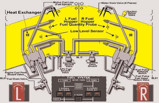
20 L-6A
21 Limitations WHAT IS THE USABLE FUEL CAPACITY? L-7
22 GIV / G400 Fuel Capacity - 29,500 lbs. (4,370 gal) G300 - Fuel Capacity - 26,900lbs NOTE: It is possible to upload fuel in excess of 29,500 pounds. This is permitted as long as the maximum ramp weight and/or maximum takeoff weight is not exceeded. L-7A
23 Limitations WHAT IS THE MINIMUM ENGINE FUEL TEMPERATURE FOR STARTING? L-8
24 -40 degrees C for starting L-8A

25 Limitations WHAT IS THE MAXIMUM ENGINE FUEL TEMPERATURE? L-9

26 +90 degrees C (Fuel temperature up to 120 degrees C for a maximum of 15 minutes permissible) L-9A
27 Limitations WHAT IS THE MINIMUM ENGINE OIL TEMPERATURE FOR THROTTLE MOVEMENT? L-10
28 -30 degrees for throttle movement L-10A
29 Limitations WHAT IS THE MAXIMUM PERMIS- SIBLE FUEL IMBALANCE: - BELOW 55,000 GW? - ABOVE 60,500 GW L-11
30 In Flight lbs. below 55,000 In Flight - 400lbs. above 60,500 Note: Sliding scale from 55,000 to 60,500 L11A
31 Electrical DISPLAY OF THE ELECTRIC POWER MONITOR PANEL E-1
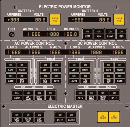
32 E-1A
33 Electrical DISPLAY OF THE AC & DC POWER CONTROL OVERHEAD PANEL E-2
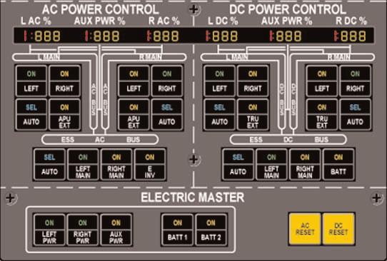
34 E-2A


35 Electrical WHAT ARE THE SPECIFICATIONS OF ALTERNATOR & CONVERTERS? E-3

36 AC Alternator - 115VAC, 3 Phase, 30 KVA Converter VAC, 400 Hz, 3 Phase, 23 KVA & 28VDC 50Amps E-3A

37 Electrical BATTERIES THE MAIN AIRCRAFT BATTERIES ARE RATED AT V / AMP/HOUR. E-4
38 TWO 24 V 40 AMP/HOUR 20 CELL NICAD E-4A

39 Electrical EXTERNAL AC POWER IS CAPABLE OF POWERING WHAT BUSES? E-5


40 EXTERNAL AC POWERS Selecting external AC power ON with the AUX PWR switch will power all buses of the aircraft electrical system. In addition, the main batteries will be charged using EXT AC. E-5A

41 Electrical WHAT BATTERY CON- NECTS TO THE GROUND SERVICE BUS? E-6
42 Battery #2 - With standard configuration, powers: wheelwell lights, utility lights, and service lights E-6A
43 Electrical WHEN WILL YOU HAVE BATTERY ON BUS? E-7
44 - The main batteries are powering the ESS DC Buses, either automatically or manually selected - Starting the APU - AUX Hydraulic pump is operating E-7A
45 Electrical WHAT ARE THE FOUR SOURCES FOR THE REMOTE POWER SUPPLY? E-8
46 2 From Aircraft Batteries 2 From Essential DC Bus E-8A
47 Electrical WHAT BUS IS POWERED BY THE E- INVERTER? E-9
48 Essential AC Bus (Phase A only) Note: E-Inverter supplies 0.8 KVA, 115 VAC, 400 Hz, Phase A only E-9A
49 Electrical WHEN EMERGENCY POWER SYSTEM IS ARMED, WHEN WILL THE E BATTS ACTI- VATE? E-10
50 3 Ways of turning on E-Batts: Manually Selected ON Loss of power on the ESS DC bus 2.5 G or greater deceleration E-10A
51 Hydraulics HYDRAULIC PAGE H-1

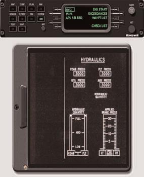
52 SPZ 8400 SPZ 8000 H-1A

53 Hydraulics WHAT CAPABILI- TIES ARE LOST IF YOU LOSE THE FLIGHT HYDRAULIC SYS- TEM PRESSURE? H-2
54 R Thrust Reverser Yaw damper (without windmilling pressure) Utility Pump Autopilot - Due to the loss of yaw damp H-2A
55 Hydraulics THE UTILITY PUMP UNIT IS DRIVEN BY FLIGHT HYDRAULIC SYSTEM PRES- SURE AND USES COMBINED HYDRAULIC SYSTEM FLUID. WHEN ARMED, WHAT WILL CAUSE IT TO TURN ON AUTOMATICALLY? H-3

56 CMB HYD FAIL CAS Message indicating less than 800 lbs pressure in the combined system. H-3A
57 Hydraulics WHAT CONDITIONS WILL PREVENT AUTOMATIC UTILITY OPERATION WHEN THE UTILITY IS ARMED? H-4
58 FLT HYD HOT CAS Message (Flight Hydraulic System fluid temperature indicating +220 degrees F or greater). H-4A
59 Hydraulics WHEN ARMED, WHAT WILL CAUSE THE AUXILIARY HYDRAULIC PUMP TO TURN ON AUTO- MATICALLY? H-5
60 - Combined & Utility Hydraulic pressure < 1500 psi and - Toe pedals depressed > 10 percent - NutCrackers in Ground Mode H-5A
61 Hydraulics THE AUXILIARY HYDRAULIC PUMP IS CAPABLE OF POWERING WHICH COMPONENTS? H-6

62 Main Entrance Door Flaps Brakes Parking/Emergency Brakes Landing Gear/Doors (Ground Only) H-6A

63 Flight Controls FLIGHT CONTROLS GIV F-1
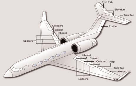
64 F-1A
65 Flight Controls GROUND SPOILERS DEPLOY AUTOMATICALLY WHEN? F-2
66 Power on - Ess DC Bus and Left Main Bus Ground spoiler switch ARMED Both power levers IDLE Nutcrackers - GROUND MODE or Flaps > 22 with wheel spin up or GPWS O Ride switch on F-2A
67 Flight Controls WHEN IS USE OF THE SPEED BRAKES PROHIBITED? F-3


68 Use of speed brakes are not approved for use with flaps at 39 (DOWN) or with landing gear extended in flight. F-3A
69 Flight Controls WHAT ARE THE MAXIMUM SPEEDS FOR FLAP EXTENSION: 10 DEGREES? 20 DEGREES? 39 DEGREES? F-4
 180 KCAS (SP)")
70 Flaps KCAS Flaps KCAS Flaps KCAS (Non-SP) 180 KCAS (SP) F-4A
71 Flight Controls WHAT IS THE MAXIMUM OPERATING ALTITUDE FOR EXTENDING FLAPS TO 10 OR 20 DEGREES? F-5
72 45,000 FT MSL F-5A
73 Flight Controls WHAT IS THE MAXIMUM OPERATING ALTITUDE FOR EXTENDING LANDING FLAPS 39? F-6
74 20,000 FT MSL F-6A
75 Master Warning ACTIVATION OF THE MASTER WARNING INHIBIT SWITCH WILL INHIBIT ALL AURAL TONES ASSOCIAT- ED WITH CAS MESSAGES EXCEPT FOR: M-1
 - CAT II Invalid")
76 - RED CAS Messages - Coupled Data Invalid (Lateral or Vertical) - CAT II Invalid M-1A
77 Master Warning WHAT ARE THE TWO (2) TYPES OF WINDSHEAR WARNINGS? M-2
 = Decreasing Performance")
78 - AMBER (Caution) = Increasing Performance - RED (Warning) = Decreasing Performance M-2A
79 Master Warning WHEN IS THE WINDSHEAR WARNING ACTIVE? M-3
80 - From Rotation to 1500' AGL - During Approach from 1500' to 10' AGL - On Missed Approach up to 1500' AGL M-3A

81 LG & Brakes WHAT IS EMERGENCY LANDING GEAR NITROGEN BLOWDOWN BOTTLE PRESSURE? LG-1
82 degrees F LG-1A
83 LG & Brakes WHAT IS THE MAXIMUM SPEED FOR GEAR RETRACTION OR EXTENTION? LG-2
84 225 knots LG-2A
85 LG & Brakes ANTI-SKID BRAKING IS AVAILABLE FROM WHICH HYDRAULIC SYSTEM(S)? LG-3
86 - Combined Hydraulic System - UTILITY System - Aux Hydraulic System LG-3A
87 LG & Brakes WHAT IS THE MAXIMUM TIRE SPEED GIV NON-SP (WITHOUT ASC 190)? LG-4
88 182 GS LG-4A
89 LG & Brakes WHAT IS THE MAXIMUM TIRE SPEED GIV SP (SN 1214 & SUB OR NON-SP WITH ASC 190)? LG-5
90 195 GS LG-5A
91 LG & Brakes WHAT IS THE MAXIMUM SPEED FOR FLYING WITH THE LANDING GEAR EXTENDED? LG-6
92 Vle = 250 KCAS LG-6A
93 LG & Brakes WHAT IS THE MAXIMUM SPEED FOR ALTERNATE EXTENSION OF THE LAND- ING GEAR (OPERATION OF THE EMER- GENCY GEAR HANDLE)? LG-7
94 175 KCAS LG-7A

95 Pneumatics/ECS PNEUMATIC SCHEMATIC P-1

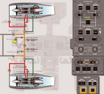
96 P-1A
97 Pneumatics/ECS WHAT IS THE MAXIMUM PERMITTED CABIN PRESSURE DIFFERENTIAL IN FLIGHT? P-2
98 9.8 psi P-2A
99 Pneumatics/ECS WHAT IS THE MAXIMUM PERMITTED CABIN PRESSURE DIFFERENTIAL FOR TAXI, TAKEOFF OR LANDING? P-3
100 0.3 psi P-3A
101 Pneumatics/ECS WHAT IS THE TEMPERATURE RANGE SELECTION IN MANUAL? P-4
102 MANUAL = Full Cold (Valve is Closed) Full Hot (Valve is Full Open) P-4A

103 Pneumatics/ECS WHAT IS THE TRIP POINT FOR THE OXYGEN SYSTEM PRESSURE RELIEF VALVE? P-5
104 A high pressure burst disc set for 2775 psi (temperature of 225 F ± 5 ). Relief flow is also vented overboard through an overboard discharge line equipped with a green rupture disc. P-5A
105 Pneumatics/ECS WHAT CABIN ALTITUDE WILL CAUSE THE PASSENGER OXYGEN MASKS TO DEPLOY? P-6

106 13,000 FT (+/-500) Cabin Altitude P-6A

107 Pneumatics/ECS WHAT ARE THE POWER SOURCES IN AUTO? IN MANUAL? P-7
108 1 AC, 1 DC powered ESS AC (Phase A) for Auto ESS DC for Manual P-7A
109 Pneumatics/ECS WHAT FUNCTIONS DOES THE CABIN SAFETY RELIEF VALVE PROVIDE? P-8
110 - Positive differential pressure relief at psi - Negative differential pressure relief at psi - Rate Limiting: 3000 /min P-8A

111 Pneumatics/ECS WHAT IS THE TEM- PERATURE RANGE SELECTION IN AUTO? P-9
112 AUTO = degrees F P-9A

113 Pneumatics/ECS WHAT ARE FOUR (4) WAYS TO OPEN THE BLEED AIR ISOLATION VALVE? P-10

114 - Isolation Valve manually selected ON - APU Bleed Air switch selected ON - Crank Master selected ON - Start Master selected ON P-10A
115 Pneumatics/ECS WHAT ARE FOUR WAYS TO ENERGIZE THE PACK VALVE CLOSED? P-11
116 Pack switch selected - OFF COOL TURB HOT caution message (ground only) Either engine start switch selected ON Ram air switch selected to RAM P-11A
117 Pneumatics/ECS DO NOT OPERATE ABOVE WHAT ALTITUDE WITHOUT BOTH ENGINE BLEEDS ON? P-12
118 41,000 P-12A

119 APU THE APU IS GUAR- ANTEED TO START AT OR BELOW WHAT ALTITUDE? AP-1
120 15,000 FT AP-1A

121 APU WILL THE APU SHUT DOWN AUTOMATI- CALLY UPON DETECTION OF A FIRE? AP-2

122 YES, THE APU WILL AUTOMATICAL- LY SHUT DOWN DURING GROUND OR FLIGHT OPERATION IF THE APU FIRE DETECTION CIRCUIT DETECTS A FIRE EXCEPT DURING USE OF THE APU FIRE TEST SWITCH. NOTE: THE FIRE BOTTLE WILL NOT DISCHARGE UNTIL THE CREW PUSHES THE APU BOTTLE DIS- CHARGE SWITCH. AP-2A

123 APU AFTER AN APU START, WHEN WILL THE APU LOAD CONTROL VALVE ALLOW APU AIR FOR ENGINE START AND PACK OPERATION? AP-3
124 APU AIR IS AVAILABLE AFTER THE APU HAS REACHED AN OPERATING SPEED OF 95% RPM OR BETTER FOR 4 SECONDS. WAIT FOR AT LEAST TWO MINUTES PRIOR TO SELECTION. AP-3A
125 APU FUEL IS SUPPLIED TO THE APU FROM WHERE? AP-4
126 FUEL IS SUPPLIED TO THE APU FROM THE LEFT WING FUEL HOPPER USING THE LEFT MAIN FUEL PUMP (THE RIGHT MAIN TANK AND PUMP MAY BE USED IF THE CROSSFLOW IS OPEN). AP-4A

127 Powerplant PULLING THE ENGINE FIRE HANDLE WILL SHUT OFF WHAT ITEMS ON THE ASSOCIATED SIDE? PP-1
128 PULLED FIRE HANDLE SHUTS OFF FUEL HYDRAULICS Reverser (on affected side) ELECTRICS PP-1A

129 Powerplant WHAT IS THE ENGINE STARTER DUTY CYCLE? PP-2
130 Powerplant CONTINUED USE OF THE STARTER IS LIMITED TO THREE (3) CRANK CYCLES, WITH A MAXIMUM OF 30 SECONDS PER CYCLE. DELAY 3 MINUTES BETWEEN START ATTEMPTS. AFTER 3 CYCLES, DELAY USE OF STARTER FOR AT LEAST 15 MINUTES. PP-2A
131 Powerplant WHAT IS THE RECOMMENDED AIRSTART ENVELOPE? PP-3
132 Powerplant 25,000 FT or below, KCAS PP-3A
133 Powerplant WHAT IS THE TGT RANGE FOR TAKE0FF POWER? PP-4
134 Powerplant Degrees C for 5 minutes or 10 minutes single engine PP-4A

135 Ice Protection WITH WING ANTI-ICE OPERATING, THE WING WARM CAPSULE LIGHT WILL ILLUMITATE AT WHAT TEMPERATURE? I-1
136 100 degrees F or warmer I-1A
137 Ice Protection USE OF COWL ANTI-ICING IS REQUIRED FOR TAXI AND TAKEOFF WHEN STATIC AIR TEMPERATURE (SAT) IS OR BELOW AND VISIBLE MOISTURE, PRECIPITATION, OR WET RUNWAY ARE PRESENT. I-2
138 +10 degrees C I-2A
139 Ice Protection THE LOW PRESSURE WARNING CAS MESSAGE WILL OCCUR WHEN? I-3
140 SN 1060 & Subs and SN Pressure drops below 10+1 PSI. SN 1190 & Subs and SN with ASC 243 Pressure drops below 4+1 PSI and after a 15 second delay NOTE: As long as the pressure is not lower than 4 psi, the aircraft will have enough bleed air to prevent ice fromation. I-3A
Examen Teórico sobre Habilitación de Tipo B (Última actualización: Septiembre 2016)
") DIRECCIÓN GENERAL DE AERONÁUTICA CIVIL DEPARTAMENTO SEGURIDAD OPERACIONAL SUBDEPARTAMENTO LICENCIAS Examen Teórico sobre Habilitación de Tipo B-737-300 (Última actualización: Septiembre 2016) Materia:
DIRECCIÓN GENERAL DE AERONÁUTICA CIVIL DEPARTAMENTO SEGURIDAD OPERACIONAL SUBDEPARTAMENTO LICENCIAS Examen Teórico sobre Habilitación de Tipo B-737-300 (Última actualización: Septiembre 2016) Materia:
EXAMEN POR MATERIAS PARA USO DE LOS POSTULANTES A LA HABILITACIÓN DE TIPO EN MATERIAL B733. ENERO 2018
 DEPARTAMENTO SEGURIDAD OPERACIONAL SUBDEPARTAMENTO LICENCIAS SECCIÓN EVALUACIONES EXAMEN POR MATERIAS PARA USO DE LOS POSTULANTES A LA HABILITACIÓN DE TIPO EN MATERIAL B733. ENERO 2018 Cantidad de Preguntas
by Greg Whiley Aussie Star Flight Simulation
 Flying the BAe 146 200/300 Version 2 by Greg Whiley Aussie Star Flight Simulation INTENTIALLY LEFT BLANK Greg Whiley Aussie Star Flight Simulation 2 Version Date Revision Version 1.0 25 June 2014 Original
Cessna Citation XLS - Electrical
 GENERAL Electrical power for the Citation XLS comes primarily from DC sources originating with the starter/ generators, the Auxiliary Power Unit (APU) or the battery. A receptacle below the left engine
Cessna Citation CE-525B CJ3 & CJ3+
 Cessna Citation CE-525B CJ3 & CJ3+ Note Taking Guide +1.307.388.0026 Document Version 1.1 27 June 2018 Aeromania, LLC 2018 2 Aeromania LLC CE 525B CJ-3 & CJ3+ Note Taking Guide Ver. 1.0 Original 1.1 New
SECTION III HYDRAULICS & LANDING GEAR
 TABLE OF CONTENTS Pilot s Manual SECTION III HYDRAULICS & LANDING GEAR Hydraulic System... 3-1 Firewall Shutoff Valves... 3-2 Source Selector Valve... 3-2 AUX HYD Pump Control... 3-2 Main/Auxiliary System
T-6B EMERGENCY PROCEDURE CRITICAL ACTION MEMORY ITEMS & OPERATING LIMITATIONS EMERGENCY PROCEDURE CRITICAL ACTION MEMORY ITEMS
 T-6B EMERGENCY PROCEDURE CRITICAL ACTION MEMORY ITEMS & OPERATING LIMITATIONS EMERGENCY PROCEDURE CRITICAL ACTION MEMORY ITEMS ABORT START PROCEDURE EMERGENCY ENGINE SHUTDOWN ON THE GROUND EMERGENCY GROUND
The Straight Word. Cessna 208 Caravan 208 Caravan I & 208B Grand Caravan Series
 The Straight Word Cessna 208 Caravan 208 Caravan I & 208B Grand Caravan Series I. FLIGHT PROCEDURES: COCKPIT PREPARATION Fuel Tank Selectors Ignition Switch Heading Bug HSI Course Indicator Altimeters
T-6B EMERGENCY PROCEDURE CRITICAL ACTION MEMORY ITEMS & OPERATING LIMITATIONS EMERGENCY PROCEDURE CRITICAL ACTION MEMORY ITEMS
 T-6B EMERGENCY PROCEDURE CRITICAL ACTION MEMORY ITEMS & OPERATING LIMITATIONS EMERGENCY PROCEDURE CRITICAL ACTION MEMORY ITEMS ABORT START PROCEDURE or STARTER switch AUTO/RESET EMERGENCY ENGINE SHUTDOWN
Boeing /-200/-200A Limitations
 Boeing 727-100/-200/-200A Limitations The information provided in this document is to be used during simulated flight only and is not intended to be used in real life. Attention VA's - you may post this
Takeoff Flaps UP 2000
 Takeoff Flaps UP 2000 30 60 75 80 85 V1 Gear UP Flap Position Indicator blanked 10 seconds after flaps UP Asymmetry Protection Near Zero Yaw Automatic unlock all surfaces (maintenance) Speedbrakes auto
Bombardier Global Express - Hydraulics
 INTRODUCTION Hydraulic power is provided by three independent and isolated systems designated 1, 2 and 3 and operate at a nominal pressure of psi. SYSTEM 1 AND 2 Systems 1 and 2 are each powered by an
EMERGENCY GEAR DOWN HANDLE CHECK VALVE GEAR DROP TO EXTEND POSITION DOOR SELECTOR DOOR SELECTOR VALVE UPLOCK RELEASE CYLINDER DOOR CYLINDER
 WARN HORN CUT BEECHJET Landing Gear System LEGEND VENT LINE PRESSURE LINE RETURN LINE NITROGEN ELECTRICAL CIRCUIT CABLE LINE PACKAGE DUMP LANDING SELECTOR CHECK SELECTOR EMERGENCY DOWN HANDLE DROP TO EXTEND
A310 MEMORY ITEMS Last Updated: 20th th October 2011
 A310 MEMORY ITEMS Last Updated: 20th th October 2011 1. Emergency Descent: Crew Oxygen Mask ON Crew Communication (Headsets) Establish Turn Initiate Descent Initiate o It is recommended to descend with
Dash8 - Q400 - Pneumatics
 12.19.1 Introduction The Auxiliary Power Unit (APU) replaces the standard composite tailcone with a titanium tailcone and firewall. The APU is accessed by two clamshell type doors on the bottom of the
FINAL EXAM. 3. Name the items on the control shift in the unmodified aircraft (non ASC-36).
.") FINAL EXAM Name 1. Total usable fuel is 177 gallons 2. Proper fuel(s) specification for the T-28 is (are): XX (a) 100/130 alternate 100LL (b) 115/145 and 100/130 alternate (c) 115/145 and 100/130 emergency
FINAL EXAM Name 1. Total usable fuel is 177 gallons 2. Proper fuel(s) specification for the T-28 is (are): XX (a) 100/130 alternate 100LL (b) 115/145 and 100/130 alternate (c) 115/145 and 100/130 emergency
Fokker 50 - Limitations GENERAL LIMITATIONS MASS LIMITATIONS. Page 1. Minimum crew. Maximum number of passenger seats.
 GENERAL LIMITATIONS Minimum crew Cockpit: Two pilots Maximum number of passenger seats Sixty-two (62) Maximum operating altitudes Maximum operating pressure altitude: Maximum take-off and landing pressure
Dornier 328Jet - Pneumatic
 ECS Control Panel Page 1 MESSAGE (SYNOPTIC) WARN INHIBIT CONDITION Location (COLOR) TONE 1 2 3 APU BLEED LEAK CAS Field (AMBER) X X LEAK (APU BLEED) Bleed air leak in APU bleed air duct. ECS Page (AMBER)
OVERHEAD PANEL PROCEDURES FLASH CARDS
 OVERHEAD PANEL PROCEDURES FLASH CARDS Boeing 737-800 A supplement to the procedures and checklists publication, Flying the Boeing 737-800 NG Greg Whiley Aussie Star Flight Simulation ELECTRICAL POWER UP
B777. Electrical DO NOT USE FOR FLIGHT
 B777 Electrical DO NOT USE FOR FLIGHT 6.10 Electrical-Controls and Indicators Electrical Panel [IFE/PASS SEATS and CABIN/UTILITY switches basic with C/L 350] 1 2 IFE/PASS CABIN/ SEATS UTILITY 3 11 APU
Embraer Systems Summary [Landing Gear & Brakes]
![Embraer Systems Summary [Landing Gear & Brakes]](/thumbs/87/96901154.jpg "Embraer Systems Summary [Landing Gear & Brakes]") GENERAL DESCRIPTION The airplane has two main landing gears and a single nose gear. Each main gear is a conventional two-wheeled landing gear. The nose gear is a conventional steerable two-wheeled unit.
GENERAL DESCRIPTION The airplane has two main landing gears and a single nose gear. Each main gear is a conventional two-wheeled landing gear. The nose gear is a conventional steerable two-wheeled unit.
POWER ON CHECK LIST COCKPIT PREPARATION
 Normal Check List DASH 8-402 1 POWER ON CHECK LIST CIRCUIT BREAKERS... CHECKED BATTERY MASTER... ON BATTERIES... ON MAIN BUS TIE... TIED EXTERNAL POWER... AS REQUIRED APU... AS REQUIRED BATTERIES & BATTERY
CHAPTER 14 LANDING GEAR
 CHAPTER 14 LANDING GEAR Page TABLE OF CONTENTS 14-00-01/02 DESCRIPTION General 14-10-01 Description 14-10-01 Controls and Indicators 14-10-04 COMPONENTS Nose Gear 14-20-01 Main and Center Gear 14-20-02
CESSNA CITATION C750 (CITATION X) PUNTA BRAVA S.A. (Rev Abril 2012)
 PUNTA BRAVA S.A. (Rev Abril 2012)") DEPARTAMENTO SEGURIDAD OPERACIONAL SUBDEPARTAMENTO LICENCIAS SECCIÓN EVALUACIONES CESSNA CITATION C750 (CITATION X) PUNTA BRAVA S.A. (Rev. 2-10 Abril 2012) A.- LIMITATIONS: 1.- Limitations ( KIAS) V (Turbulence
DEPARTAMENTO SEGURIDAD OPERACIONAL SUBDEPARTAMENTO LICENCIAS SECCIÓN EVALUACIONES CESSNA CITATION C750 (CITATION X) PUNTA BRAVA S.A. (Rev. 2-10 Abril 2012) A.- LIMITATIONS: 1.- Limitations ( KIAS) V (Turbulence
Canadair Regional Jet 100/200 - Auxiliary Power Unit
 1. INTRODUCTION The auxiliary power unit (APU) is installed within a fireproof titanium enclosure in the aft equipment compartment. The APU is a fully automated gas turbine power plant which drives an
David s Flight Simulator Operations Manual
 DPW Solutions David s Flight Simulator Operations Manual Draft 0.2 David Woolterton Update 10/5/2016 Table of Contents Pre-Start Checklist... 2 Startup Checklist... 3 Before Taxi Checklist... 3 Taxi Checklist...
DASSAULT AVIATION Proprietary Data
 F900EX EASY 02-27-00 CODDE 1 PAGE 1 / 2 TABLE OF CONTENTS 02-27 02-27-00 TABLE OF CONTENTS 02-27-05 GENERAL Introduction Flight control sources Primary and secondary flight controls 02-27-10 DESCRIPTION
King Air B90. Speeds (KIAS)
") King Air B90 Speeds (KIAS) V MCA 92 V SSE (101) Derived from C90 V X 101 V Y 114 Down to 103 @ 30 000 V XSE 101 V YSE 110 Down to 101 @ 24 000 V A 169 V R 92 V 1 101 V MO 208 V FE 174 35% 130 100% V LE
King Air B90 Speeds (KIAS) V MCA 92 V SSE (101) Derived from C90 V X 101 V Y 114 Down to 103 @ 30 000 V XSE 101 V YSE 110 Down to 101 @ 24 000 V A 169 V R 92 V 1 101 V MO 208 V FE 174 35% 130 100% V LE
Landing Gear & Brakes
 EMBRAER 135/145 Landing Gear & Brakes GENERAL The EMB-145 landing gear incorporates braking and steering capabilities. The extension/retraction, steering and braking functions are hydraulically assisted,
ifly Jets: The 737NG Quick Reference Handbook Revision Number: 3 Revision Date: July 26, 2010
 ifly Jets: The 737NG ifly Jets: The 737NG Revision Number: 3 Revision Date: July 26, 2010 http://www.iflysimsoft.com/ The ifly Developer Team WARNING This manual is only used for understanding the functionalities
HYDRAULICS & LANDING GEAR
 IC~--u U ; ~~^U ul'h HYDRAULICS & LANDING GEAR TABLE OF CONTENTS Hydraulic System.....................................................................................3-1 HYD PUMP Switch................................................................................3-2
The Straight Word. Beechcraft 90 King Air B90 Series. Condition Lever. Set for Takeoff Cabin Altitude Controller Set Cruise Level + 1
 The Straight Word Beechcraft 90 King Air B90 Series I. FLIGHT PROCEDURES: COCKPIT PREPARATION Heading Bug Set QFU HSI Course Indicator Set Course Altimeters Set QNH Power Levers Idle Propeller Levers Max
CHAPTER 1 AIRCRAFT GENERAL
 CHAPTER 1 AIRCRAFT GENERAL INTRODUCTION This manual provides a description of the major airframe and engine systems in the Cessna Citation Mustang (Figure 1-1). This material does not supersede, nor is
MAJESTIC Q400 SHARED COCKPIT FLOWS CHECKLISTS MULTIPLAYER OPERATIONS.
 PRE LOAD IN Agree on Ports, Share IP and select who will be doing W&B. INITIAL LOAD IN On 1 System transfer Weight and Balance to Simulator Pause Simulation Save Flight as normal FSX Flight Transfer Save
REFERENCE: 2861 wings 2044 trunk 4904 total BEW 10,655 BOW 11,185 Max Useful load 5115 MLanding ZFW FUEL BURNS 11min min min
 REFERENCE: 2861 wings 2044 trunk 4904 total BEW 10,655 BOW 11,185 Max Useful load 5115 MLanding 15700 ZFW 13000 FUEL BURNS 11min 357 27min 730 36 min 940 58min 1453 1:17 1800 2:20 2933 2:46 3283 3:00 3600
Pneumatic Air Conditioning System Citation, Citation I
 Pneumatic Air Conditioning System Citation, Citation I COCKPIT VENT FOOT WARMER OVERHEAD COCKPIT WINDSHIELD WEMAC OPTIMAL VENT OVERHEAD CONDITIONED AIR DUCTS BLOWER SIDE WINDOW UNDER FLOOR CONDITIONED
DCS L-39 ALBATROS REAL PILOT START-UP, TAXI AND TAKEOFF CHECKLISTS V 1.0 PREPARED BY LINO_GERMANY
 DCS L-39 ALBATROS REAL PILOT START-UP, TAXI AND TAKEOFF CHECKLISTS V 1.0 PREPARED BY LINO_GERMANY T.O. 1T-L39C-1.0 P1 INTRODUCTIONS A. CHECKLISTS This compilation contains amplified normal and (hopefully
GACE Flying Club Aircraft Review Test 2018 N5312S & N5928E. Name: GACE #: Score: Checked by: CFI #:
 GACE Flying Club Aircraft Review Test 2018 N5312S & N5928E Name: GACE #: Score: Checked by: CFI #: Date: (The majority of these questions are for N5312S. All N5928E questions will be marked 28E) 1. What
Dassault Falcon 50 Microsoft Flight Simulator 2004
 Dassault Falcon 50 Microsoft Flight Simulator 2004 Model and bitmaps Yannick Lavigne Custom gauge programming Fred Banting Flight dynamics Rob Young and Eric Dantes. Foto: Gerry Stegmeier Foto: Dassault
System Normal Secondary Direct. All 3 PFC work in parallel. available. Pitch Normal Secondary Direct. Pitch maneuver command.
 Flight s System Normal Secondary Direct Primary Flight Computers (PFC) Three Primary Flight Computers use control wheel and pedal inputs from the pilot to electronically the primary flight control surfaces
AIRCRAFT SYSTEMS HYDRAULIC
 Intentionally left blank PRELIMINARY PAGES - TABLE OF CONTENTS DSC-29-10 Description DSC-29-10-10 General GENERAL... A DSC-29-10-20 Generation GREEN SYSTEM PUMP...A BLUE SYSTEM PUMPS...B YELLOW SYSTEM
Fokker 50 - Landing Gear
 LANDING GEAR OPERATION Features General The Landing Gear (LG) consists of a forward retracting nose gear and two rearward retracting main gears. Doors enclose the landing gear bays. The LG is retracted
Owners Manual. Table of Contents 4.1. INTRODUCTION SPEEDS FOR NORMAL OPERATION CHECKLIST & PROCEDURES 4
 NORMAL OPERATIONS Table of Contents 4.1. INTRODUCTION 2 4.2. SPEEDS FOR NORMAL OPERATION 2 4.3. CHECKLIST & PROCEDURES 4 4.3.1. PREFLIGHT INSPECTION 4 4.3.2. BEFORE STARTING ENGINE 8 4.3.3. STARTING ENGINE
Bombardier Challenger Auxiliary Power Unit
 GENERAL A Honeywell 36 150(CL) constant-speed gas turbine auxiliary power unit (APU) is installed within a fire-resistant compartment in the aft equipment bay. The APU drives a generator, providing AC
Introduction. APU Location
 B737 NG APU Introduction The auxiliary power unit (APU) is a self contained gas turbine engine installed within a fireproof compartment located in the tail of the airplane. The APU supplies bleed air for
SECTION IV ELECTRICAL & LIGHTING
 SECTION IV ELECTRICAL & LIGHTING TABLE OF CONTENTS Electrical Power Systems... 4-1 Introduction... 4-1 General... 4-1 Main Batteries... 4-2 Emergency Battery... 4-3 Generators... 4-4 Generator Control
General. APU Control System. APU Door System
 .10 -Description and Operation General The Auxiliary Power Unit () provides electrical and pneumatic power for engine start and air conditioning, and supplies ground and in-flight electrical power. Pneumatic
CHAPTER 6 ELECTRICAL SYSTEMS
 CHAPTER 6 ELECTRICAL SYSTEMS Page TABLE OF CONTENTS 06-00-01/02 DESCRIPTION General 06-10-01 Description 06-10-01 Controls and Indicators 06-10-02 COMPONENTS Circuit Breaker Panel Locations 06-20-01/02
Vso 61. Vs1 63. Vr 70. Vx 76. Vxse 78. Vy 89. Vyse. 89 (blue line) Vmc. 61 (radial redline) Vsse 76. Va 134) Vno 163
 Vmc. 61 (radial redline) Vsse 76. Va 134) Vno 163") PA34-200T Piper Seneca II Normal procedures V-speeds Knots Vso 6 Vs 63 Vr 70 Vx 76 Vxse 78 Vy 89 Vyse Vmc 89 (blue line) 6 (radial redline) Vsse 76 Va 2-36(@4507lbs 34) Vno 63 Vfe 38 (0*)/2(25*)/07(40*)
PA34-200T Piper Seneca II Normal procedures V-speeds Knots Vso 6 Vs 63 Vr 70 Vx 76 Vxse 78 Vy 89 Vyse Vmc 89 (blue line) 6 (radial redline) Vsse 76 Va 2-36(@4507lbs 34) Vno 63 Vfe 38 (0*)/2(25*)/07(40*)
SECTION 2-05 ELECTRICAL
 SECTION 2-05 TABLE OF CONTENTS Block General...2-05-05...01 DC System...2-05-05...02 DC System Protection...2-05-05...04 External Power Source...2-05-05...05 Batteries...2-05-05...06 Backup Battery...2-05-05...07
Elmendorf Aero Club Aircraft Test
 DO NOT WRITE ON THIS TEST FEB 2014 Elmendorf Aero Club Aircraft Test Cessna - 185 For the following questions, you will need to refer to the Pilots Information Manual for the C-185F and Graphic Engine
AIRCRAFT SYSTEMS PNEUMATIC
 Intentionally left blank PRELIMINARY PAGES - TABLE OF CONTENTS DSC-36-10 Description DSC-36-10-10 General GENERAL... A DSC-36-10-20 Engine Bleed System GENERAL... A Architecture... B Air Bleed Selection...C
DASSAULT AVIATION Proprietary Data
 F900EX EASY 02-30-00 CODDE 1 PAGE 1 / 2 TABLE OF CONTENTS 02-30 02-30-00 TABLE OF CONTENTS 02-30-05 GENERAL Introduction Anti-icing protection sources Anti-ice system location overview 02-30-10 DESCRIPTION
1. Aircraft General (0 Hours 39 minutes) 2. Doors (0 Hours 33 minutes) 3. EFIS (2 Hours 55 minutes) 4. Exterior Lighting (0 Hours 24 minutes)
 2. Doors (0 Hours 33 minutes) 3. EFIS (2 Hours 55 minutes) 4. Exterior Lighting (0 Hours 24 minutes)") Course: CRJ900 (Pilot) Delivery Formats: Web Based or Portable Classroom Number of modules: 26 Estimated Course Time: 36 Hours 16 minutes The following topics are included in this CRJ900 (Pilot) CBT/WBT
Course: CRJ900 (Pilot) Delivery Formats: Web Based or Portable Classroom Number of modules: 26 Estimated Course Time: 36 Hours 16 minutes The following topics are included in this CRJ900 (Pilot) CBT/WBT
AIRCRAFT GENERAL KNOWLEDGE (1) AIRFRAME/SYSTEMS/POWERPLANT
 AIRFRAME/SYSTEMS/POWERPLANT") 1 In flight, a cantilever wing of an airplane containing fuel undergoes vertical loads which produce a bending moment: A highest at the wing root B equal to the zero -fuel weight multiplied by the span
1 In flight, a cantilever wing of an airplane containing fuel undergoes vertical loads which produce a bending moment: A highest at the wing root B equal to the zero -fuel weight multiplied by the span
ARIANA AFGHAN AIRLINES MPD Tally Sheet - Routine Jobs
 B737-400 YA-PID 26085 Kabul AFG-PID-26085-1217 MPD (C2-CHECK) 1 of 15 1. 20-020-31-01 B20-20-31-6C 203 204 INSPECT THE CONTROL CABLES FOR BROKEN WIRES AND WEAR IN THE NLG WHEEL WELL. DI 2. 20-020-32-01
USAF Aero Club T-41B (Cessna R-172E) Aircraft Exam Updated February 2017
 Aircraft Exam Updated February 2017") USAF Aero Club T-41B (Cessna R-172E) Aircraft Exam Updated February 2017 Instructions Complete the supplement following exam using the answer sheet provided. Do not assume information not specifically
USAF Aero Club T-41B (Cessna R-172E) Aircraft Exam Updated February 2017 Instructions Complete the supplement following exam using the answer sheet provided. Do not assume information not specifically
DASSAULT AVIATION Proprietary Data
 F2000EX EASY 02-27-00 CODDE 1 PAGE 1 / 2 TABLE OF CONTENTS 02-27 02-27-00 TABLE OF CONTENTS 02-27-05 GENERAL Introduction Flight control sources Primary and secondary flight controls 02-27-10 DESCRIPTION
TECNAM P2004 BRAVO N128LS
 TECNAM P2004 BRAVO N128LS GENERAL INFORMATION NORMAL PROCEDURES TIME SENSITIVE EMERGENCY TECNAM P2004 BRAVO CHECKLIST [FLIGHT PLAN DESIGNATION IS BRAV ] EMERGENCY CONTACT The following are First Landings'
B737 NG Anti Ice & Rain
 B737 NG Anti Ice & Rain Introduction Thermal anti-icing (TAI), electrical anti-icing, and windshield wipers are the systems provided for ice and rain protection. The anti-ice and rain systems include:
INDEX. Preflight Inspection Pages 2-4. Start Up.. Page 5. Take Off. Page 6. Approach to Landing. Pages 7-8. Emergency Procedures..
 INDEX Preflight Inspection Pages 2-4 Start Up.. Page 5 Take Off. Page 6 Approach to Landing. Pages 7-8 Emergency Procedures.. Page 9 Engine Failure Pages 10-13 Propeller Governor Failure Page 14 Fire.
/200/300/400/500 SERIES FLAMMABLE MATERIAL LOCATIONS
 73737-100/200/300/400/500 SERIES FLAMMABLE MATERIAL LOCATIONS (tab) 1 390/492/984 GAL - 1476/1862/3725 L WINGLETS OPTIONAL AUXILIARY FUEL TANK IN LWR AFT CARGO COMPARTMENT VENT SURGE TANK FUEL TANK No.
CHAPTER 7 ABNORMAL FLOWS AND CHECKLISTS TABLE OF CONTENTS
 CHAPTER 7 ABNORMAL FLOWS AND CHECKLISTS TABLE OF CONTENTS ELECTRICAL FAULTS...3 Alternator Failure / Low Voltage...3 INSTRUMENTS...7 Low vacuum indication / vacuum failure...7 Erroneous airspeed / altitude
DASSAULT AVIATION Proprietary Data
 F2000EX EASY 02-49-00 CODDE 1 PAGE 1 / 2 TABLE OF CONTENTS 02-49 02-49-00 TABLE OF CONTENTS 02-49-05 GENERAL Introduction Sources Equipment location 02-49-10 DESCRIPTION Introduction Description Operating
Central Warning Systems
 CIRRUS AIRPLANE MAINTENANCE MANUAL Central Warning Systems CHAPTER 31-50: CENTRAL WARNING SYSTEMS GENERAL 31-50: CENTRAL WARNING SYSTEMS 1. General This section describes the Indicating/Recording Systems
AIR TRACTOR, INC. OLNEY, TEXAS
 TABLE OF CONTENTS LOG OF REVISIONS... 2 DESCRIPTION... 4 SECTION 1 LIMITATIONS... 5 SECTION 2 NORMAL PROCEDURES... 8 SECTION 3 EMERGENCY PROCEDURES... 8 SECTION 4 MANUFACTURER'S SECTION - PERFORMANCE...
Answer Key. Page 1 of 10
 Name: Answer Key Score: [1] When range and economy of operation are the principal goals, the pilot must ensure that the airplane will be operated at the recommended A. equivalent airspeed. B. specific
TECNAM P92 EAGLET N615TA TECNAM P92 EAGLET CHECKLIST [FLIGHT PLAN DESIGNATION IS ECHO ]
![TECNAM P92 EAGLET N615TA TECNAM P92 EAGLET CHECKLIST [FLIGHT PLAN DESIGNATION IS ECHO ]](/thumbs/86/93080937.jpg "TECNAM P92 EAGLET N615TA TECNAM P92 EAGLET CHECKLIST [FLIGHT PLAN DESIGNATION IS ECHO ]") TECNAM P92 EAGLET CHECKLIST [FLIGHT PLAN DESIGNATION IS ECHO ] EMERGENCY CONTACT The following are First Landings' emergency contact telephone numbers. We ask that you call the numbers in the order listed.
TECNAM P92 EAGLET CHECKLIST [FLIGHT PLAN DESIGNATION IS ECHO ] EMERGENCY CONTACT The following are First Landings' emergency contact telephone numbers. We ask that you call the numbers in the order listed.
FLASHCARDS AIRCRAFT. Courtesy of the Air Safety Institute, a Division of the AOPA Foundation, and made possible by AOPA Services Corporation.
 AIRCRAFT FLASHCARDS Courtesy of the Air Safety Institute, a Division of the AOPA Foundation, and made possible by AOPA Services Corporation. Knowing your aircraft well is essential to safe flying. These
General. Gear Retraction and Extension
 Land.10 Landing Gear and Brakes-Description and Operation General The aircraft has a tricycle landing gear consisting of four-wheel trucks on each main gear, dual wheels on the nose gear, and a dual wheel
DASSAULT AVIATION Proprietary Data
 F2000EX EASY 02-24-00 CODDE 1 PAGE 1 / 2 TABLE OF CONTENTS 02-24 02-24-00 TABLE OF CONTENTS 02-24-05 GENERAL Introduction Sources Equipment location 02-24-10 DESCRIPTION Generation Distribution Operation
Elmendorf Aero Club Aircraft Test
 DO NOT WRITE ON THIS TEST FEB 2013 Elmendorf Aero Club Aircraft Test Cessna - 172 For the following questions, you will need to refer to the Pilots Information Manual for the C-172R (180hp). The bonus
Dash8-200/300 - Auxiliary Power Unit APU CONTROLS AND INDICATORS. Page 1
 APU CONTROLS AND INDICATORS Page 1 APU control and indicators Page 2 closed APU controls and indicators Page 3 SYSTEM DESCRIPTION General The auxiliary power unit (APU) is a gas turbine engine, located
Elmendorf Aero Club Aircraft Test
 DO NOT WRITE ON THIS TEST JAN 2014 Elmendorf Aero Club Aircraft Test SENECA II For the following questions, you will need to refer to the Pilots Information Manual for the PA-34-200T. USE ANSWER SHEET
JODEL D.112 INFORMATION MANUAL C-FVOF
 JODEL D.112 INFORMATION MANUAL C-FVOF Table of Contents I General Description...4 Dimensions:...4 Powertrain:...4 Landing gear:...4 Control travel:...4 II Limitations...5 Speed limits:...5 Airpeed indicator
Jump to Table of Contents
 Jump to Table of Contents PIPER AIRCRAFT CORPORATION PA-28R-201, CHEROKEE ARROW III SECTION 3 EMERGENCY PROCEDURES 3.3 EMERGENCY PROCEDURES CHECK LIST ENGINE FIRE DURING
AIRBUS A319/320/321 Technical Ground School Study Guide July 1, 2004 (Updated 1/18/05)
") AIRBUS A319/320/321 Technical Ground School Study Guide July 1, 2004 (Updated 1/18/05) PART ONE Chapter 6: Ice & Rain Protection 1. Is it permitted to select WING ANTI-ICE pushbutton on the ground? On
AIRBUS A319/320/321 Technical Ground School Study Guide July 1, 2004 (Updated 1/18/05) PART ONE Chapter 6: Ice & Rain Protection 1. Is it permitted to select WING ANTI-ICE pushbutton on the ground? On
DASSAULT AVIATION Proprietary Data
 F2000EX EASY 02-28-00 CODDE 1 PAGE 1 / 2 TABLE OF CONTENTS 02-28 ATA 28 - FUEL SYSTEM 02-28-00 TABLE OF CONTENTS 02-28-05 GENERAL Introduction Sources Fuel tank location 02-28-10 DESCRIPTION Sub-systems
SECTION 2-14 PNEUMATICS, AIR CONDITIONING AND PRESSURIZATION
 AIRPLANE PNEUMATICS SECTION 2-14 PNEUMATICS, TABLE OF CONTENTS Block General... 2-14-05..01 Pneumatic System... 2-14-05..02 Pneumatic System Function Logic... 2-14-05..06 Cross Bleed Valve Operational
Checklist Robin DR40
 Flight Checklist for Normal Operations Massgebend ist das AFM (Parameters, Restrictions, Emergency, etc.) Jan 18 1 COCKPIT PREPARATION BEFORE STARTING ENGINE 1 Aircraft + Cockpit Inspection COMPLETED 1
IN-FLIGHT CHECK LIST B-17 Technical Session for Flight Engineers 11/18/2017 (with REVISION)
") IN-FLIGHT CHECK LIST B-17 Technical Session for Flight Engineers 11/18/2017 (with REVISION) Check Lists became an integral part of aviation following the tragic loss of Boeing 299 the prototype for the
IN-FLIGHT CHECK LIST B-17 Technical Session for Flight Engineers 11/18/2017 (with REVISION) Check Lists became an integral part of aviation following the tragic loss of Boeing 299 the prototype for the
ATA 36 PNEUMATIC TABLE OF CONTENTS DGT ATA 36 PNEUMATIC TABLE OF CONTENTS GENERAL Introduction Sources
 F900EX EASY 02-36-00 CODDE 1 PAGE 1 / 2 TABLE OF CONTENTS 02-36 02-36-00 TABLE OF CONTENTS 02-36-05 GENERAL Introduction Sources 02-36-10 DESCRIPTION Introduction Main sub-systems Distribution 02-36-15
At all times use approved company publications and aircraft manufacturer manuals as sole reference for procedures and data!
 Disclaimer These notes have not been approved by any aviation administration, by any airline nor by the aircraft manufacturer to whom it refers. At all times use approved company publications and aircraft
ASSIGNMENT Chapter 4 AIRCRAFT ELECTRICAL SYSTEMS
 ASSIGNMENT Chapter 4 AIRCRAFT ELECTRICAL SYSTEMS 4-1. What are the two most common types of bulb bases? A. Single wire and single contact B. Doubled filament and index C. Single and double contact bayonet
PA28R ARROW CHECKLIST
 PA28R ARROW CHECKLIST 2300.11.0112 1 Normal Procedures Initial PREFLIGHT CHECK General Appearance... CHECKED Position & Taxi Path... CHECKED Tie Downs, Locks, Chocks & Covers... REMOVED Cockpit Controls...UNLOCKED
AFTER PF LANDING PARKING PNF SECURING THE A/C A320
 AFTER LANDING PF PARKING SECURING THE A/C A320 - Version 04a 1.a. AFTER LANDING Depending on the taxi position : ANNOUNCE.. LANDING LIGHTS GRND SPLRS..DISARM LAND LIGHTS..... RETRACT STROBE...AUTO Signal
Owners Manual. Table of Contents 3.1. INTRODUCTION AIRSPEEDS FOR EMERGENCY OPERATION OPERATIONAL CHECKLISTS 3
 EMERGENCY PROCEDURES Table of Contents 3.1. INTRODUCTION 2 3.2. AIRSPEEDS FOR EMERGENCY OPERATION 2 3.3. OPERATIONAL CHECKLISTS 3 3.3.1. ENGINE FAILURES 3. ENGINE FAILURE DURING TAKEOFF RUN 3. ENGINE FAILURE
DO NOT WRITE ON THIS TEST FEB 2013 Elmendorf Aero Club Aircraft Test. Cessna - 182
 DO NOT WRITE ON THIS TEST FEB 2013 Elmendorf Aero Club Aircraft Test Cessna - 182 For the following questions, you will need to refer to the Pilots Information Manual for the C-182R. The bonus questions
EMERGENCY PROCEDURES ENGINE FIRE DURING START/GROUND OPERATIONS STARTER ENERGIZED ANNUNCIATOR ILLUMINATED. Memory items are printed in red.
 ENG FIRE-GRND, STARTER ENERGIZED EMERGENCY PROCEDURES Memory items are printed in red. ENGINE FIRE DURING START/GROUND OPERATIONS 1. Mixture...IDLE CUTOFF 2. Fuel Selector Valve... OFF 3. Battery, Alternator,
Initial / Recurrent Ground Take-Home Self-Test: The Beechcraft 58 Baron Systems, Components and Procedures
 Initial / Recurrent Ground Take-Home Self-Test: The Beechcraft 58 Baron Systems, Components and Procedures Flight Express, Inc. This take-home self-test partially satisfies the recurrent ground training
CESSNA SECTION 4. Unless otherwise noted, the following speeds are based on a maximum weight of 2550 pounds and may be used for any lesser weight.
 CESSNA SECTION 4 INTRODUCTION Section 4 provides procedures and amplified instructions for normal operations using standard equipment. Normal procedures associated with optional systems can be found in
I. DISPATCH PLANNING & AIRCRAFT EXTERIOR CHECK
 SCHODACK AVIATION Page 1 of 10 I. DISPATCH PLANNING & AIRCRAFT EXTERIOR CHECK 1. Flight Planning 1. Aircraft requirements & preparation: Required aircraft documents: Airworthiness Certificate Registration
SECTION II AIRPLANE AND SYSTEMS MODEL 750 HYDRAULIC
 HYDRAULIC The main hydraulic system is comprised of two independent systems; system A and system B. Hydraulic power is used to power the primary flight controls (rudder, elevators, ailerons, and roll spoilers),
ATA 49 AUXILIARY POWER UNIT
 F900EX EASY 02-49-00 CODDE 1 PAGE 1 / 2 TABLE OF CONTENTS 02-49 02-49-00 TABLE OF CONTENTS 02-49-05 GENERAL Introduction Sources APU location 02-49-10 DESCRIPTION Introduction Description Operating principle
Van s Aircraft RV-7A. Pilot s Operating Handbook N585RV
 Van s Aircraft RV-7A Pilot s Operating Handbook N585RV PERFORMANCE SPECIFICATIONS SPAN:..25 0 LENGTH...20 4 HEIGHT:.. 7 10 SPEED: Maximum at Sea Level...180 knots Cruise, 75% Power at 8,000 Ft...170 knots
The Citation Sovereign is certified in accordance with 14 CFR Part 25 (to Amendment 98).
.") MODEL 680 SECTION I DESCRIPTION AND SPECIFICATIONS OPERATING LIMITATIONS NOTICE CERTIFICATION AND OPERATIONAL LIMITATIONS ARE CONDITIONS OF THE TYPE AND AIRWORTHINESS CERTIFICATES AND MUST BE COMPLIED
MODEL 680 SECTION I DESCRIPTION AND SPECIFICATIONS OPERATING LIMITATIONS NOTICE CERTIFICATION AND OPERATIONAL LIMITATIONS ARE CONDITIONS OF THE TYPE AND AIRWORTHINESS CERTIFICATES AND MUST BE COMPLIED
PA GURW (December 30, 2000) PRE-START. Langley Flying School. Airspeeds (MPH) for Safe Operation. Cockpit Checks
 PRE-START. Langley Flying School. Airspeeds (MPH) for Safe Operation. Cockpit Checks") Langley Flying School PA-34-200 GURW (December 30, 2000) Airspeeds (MPH) for Safe Operation V y (all weights) 105 V x (all weights) 90 En Route Climb 120 V mc 80 V yse 105 V xse 93 V r 80 V r (25 Flaps)
Langley Flying School PA-34-200 GURW (December 30, 2000) Airspeeds (MPH) for Safe Operation V y (all weights) 105 V x (all weights) 90 En Route Climb 120 V mc 80 V yse 105 V xse 93 V r 80 V r (25 Flaps)
PA-28R 201 Piper Arrow
 Beale Aero Club Aircraft Written Test PA-28R 201 Piper Arrow (Required passing score: 80%) 1. If an engine power loss occurs immediately after take off, the pilot s reaction should be to: a. maintain safe
PREFLIGHT CHECK COCKPIT RIGHT WING. NORMAL PROCEDURRES CHECKLIST PA-28RT 201 Arrow IV
 NORMAL PROCEDURRES CHECKLIST PA-28RT 201 Arrow IV PREFLIGHT CHECK COCKPIT Control Wheel -- Release Restraints Avionics -- OFF Parking Brake -- SET All Switches -- OFF Mixture -- IDLE CUT-OFF Master Switch
AIRPLANE OPERATIONS MANUAL SECTION 2-15
 SECTION 2-15 TABLE OF CONTENTS Block General... 2-15-05..01 Bleed Air Thermal Anti-Icing System... 2-15-10..01 Wing, Stabilizer and Engine Anti-icing Valves Operational Logic... 2-15-10..04 EICAS Messages...