ECM-MSPD. Installation, Operation, and Maintenance Manual
|
|
|
- Simon White
- 5 years ago
- Views:
Transcription

1 ECM-MSPD Installation, Operation, and Maintenance Manual READ AND SAVE THESE INSTRUCTIONS The purpose of this manual is to aid in the proper installation and operation of fans manufactured by S&P. These instructions are intended to supplement good general practices and are not intended to cover detailed instruction procedures, because of the wide variety and types of fans manufactured by S&P Powers Ave Jacksonville, FL P: F: ECM-MSPD-IOM_v

2 Installation Instructions ECM-MSpd EC Motor Control 1. APPLICATION The ECM-MSpd allows switches, ~24V thermostats and ~24V controls to select one of two adjustable speed indexes for an EC Motor. A single diode-multiplexed switch allows up to two speed settings. The speed for each setting can be adjusted when it is activated. The adjustment range is from Off to 100% of the motor s programmed control range. When changing speeds, the ECM-MSpd control adjusts the speed index¹ at a gradual 1% per second rate. This ramping feature reduces occupant awareness of changes in diffuser airflow. 2. FEATURES Isolated Diode-Multiplexed Switch PWM or 0 to +10V Output Gradual or Fast Speed Change Pilot Pulse Enable/Disable 3. ORDERING EVO/ECM-MSPD PART ID DESCRIPTION Circuit Board Version 4. SPECIFICATIONS Power Switch Speed Selection (see wiring) ~24V ±20% 50/60 Hz NEC UL 1310 Class2 USA +24V NEC Class II USA 2 W, 4 VA + 1VA/Motor 1k8 Ω load Two Speed Only +24V ± 20% OUTPUTS Motor Control no jumper with jumper PWM² 10 ma (See Options) 0 to +10 V 10 ma (See Options) PWM² Supports Pilot Pulse (Autoswitch) Function Therm. Stability Operating Environment Connections <0.0%/ F 0 F to 130 F (-18 C to 55 C) 10-80% rh 1 /4 Tabs 1 Speed Index = %PWM except at the end points 2 PWM = Pulse Width Modulation 1

3 5. ADJUSTMENT For accurate speed adjustment, a volt meter is required to read the percent voltage. 0 to +1V = 0 to 100% PWM Example: for an 1800 RPM motor, 0.50V = 900 RPM Notes: Ramping is temporarily disabled in the adjustment mode. Verify with manufacturer on motor minimum speeds as motor will not turn below minimum speeds. Single Speed Adjustment (No Switch Installed) 1. Insert volt meter probe into the Speed Test ports. 2. Enter the speed adjustment mode by rotating the Adjust Speed shaft until the flashing LED turns solid green. 3. While in speed adjustment mode, continue to turn the shaft to the desired speed using the percent voltage value as a reference. 4. Once desired speed is reached, the speed setting will be saved after eight seconds. This is noted when the solid LED returns to flashing. Dual Speed Adjustment (Switch is Installed) 1. Insert volt meter probe into the Speed Test ports. 2. Turn switch to ON position. 3. Enter the speed adjustment mode by rotating the Adjust Speed shaft until the flashing LED turns solid green. 4. While in speed adjustment mode, continue to turn the shaft to the desired speed using the percent voltage value as a reference. 5. Once desired speed is reached, the speed setting will be saved after eight seconds. This is noted when the solid LED returns to flashing. 6. Turn switch to OFF position and repeat steps Green LED The green LED continuously indicates the speed. After a pause, the lamp flashes out the tens digit, then the units digit of a number between 0 and 100. Long flashes represent the tens digit, and short flashes represent the units digit. For example, a speed of 23% flashes two longs, then three shorts. Two extra-long flashes indicate a speed of 0. An extra-long flash and ten short flashes indicates a speed of 100%. The lamp flashes the speed that was present when the flash sequence started. The lamp stops flashing and stays lit when in adjustment mode in. 66 mm in. 41 mm. 2


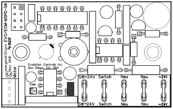
4 7. MOUNTING Mount the control inside a metal control cabinet or enclosure. Fasten the control mounting posts to an earthed metal surface. Use #8 flat or oval head screws through the two metallic mounting posts. The countersink taper forces a good earth connection between the mounting post and the PC board. Mounting posts are 3/32 (2.38 mm) ID. Adjustment shafts are.20 (5 mm) dia. Mount the control with clearance for the ~24V power wires and control cable connector. Mount the control so the green LED is visible. Make sure there is access to the test points and the Adjust shaft. 8. OPTIONS OPTIONS Power Supply Jumper Block J4 Pilot Pulse Output Type Ramp Disable DESCRIPTION Insert jumper when the controller and the call signals share the same power supply. Remove jumper when controller and call signals are powered by different transformers (see Wiring). N/A Insert jumper so the PWM never goes below 0.4% or above 99.6%. Some profiles allow the motor to run in an alternate mode when there is no pulse on the PWM input. Insert jumper for 0 to +10V motor control. Remove jumper for PWM motor control Insert jumper to disable the 1% PWM/ second ramp rate (no delay). Power Supply Jumper 9. WIRING Power the ECM-MSpd controller with a ~24V NEC UL 1310 Class 2 USA power source. DC voltages from +20V to +30V may also be used to power the control. Observe all code requirements and follow all safety practices regarding low voltage power supplies and circuits to insure a safe, reliable installation. Earth one side of the power source. Connect the neutral connection to the earthed side of the ~24V Class 2 power source. Some applications may require an isolated power supply or alternative earthing scheme. Follow code requirements and observe all safety practices concerning unearthed low voltage circuits. Connect the ~24V connection to the hot side of the ~24 Class 2 power source. You may interrupt this connection to turn off the controller and stop the EC Motor. This is especially useful if you plan to set a flow when the switch is off (no signal at the Switch tab). Many automation controllers will power the ECM-MSpd controller directly from an on/off output. The Switch tab is optically isolated from other ECM-MSpd circuitry. To use the same power as the control, install the ~24V jumper to internally connect SW~24V to the internal ~24V power. For simple two speed operation, install the ~24V jumper and connect a switch between SW~24V and SW. 3 If DC voltage is used to power the control and the switch, it can only be used for dual speed control. For multiple speeds, a second ~24VAC transformer must be used to power the switch. 3
5 10. SINGLE SPEED 11. DUAL SPEED 4
6 5
7 6
8
Evolution. ECM Motor. T Control CONTROLS INC. EVO /ECM-DTC16. Differential Temperature Control. Specifications. Applications
 T Control CONTROLS INC. EVO /ECM-DTC16 Differential Temperature Control The EVO/ECM-DTC16 sets the ECM motor speed depending on the temperature difference measured by two temperature sensors. The DTC16
Products for Indoor Air Quality and Control
 Products for Indoor Air Quality and Control Constant Volume Fan Powered Units AC_J Series ECM Motor Technical Guide Page 1 Table of Contents General Information Page Number ECM Motor Introduction 3 Design
INSTALLATION & OPERATION MANUAL. Fan Powered Terminals VAV TERMINALS. Redefine your comfort zone.
 INSTALLATION & OPERATION MANUAL Fan Powered Terminals VAV TERMINALS IOM FAN POWERED TERMINALS Receiving Inspection After unpacking the terminal, check it for shipping damage. If any shipping damage is
Fan Coil Unit (FCU) Fan Motor Control
 Fan Motor Control") Fan Coil Unit (FCU) Fan Motor Control Fan Relay Board 2 (FRBii) Installation, Operation, and Maintenance The Fan Relay Board assembly (FRBii) provides electronic control for the fan motor and various connections
Fan Coil Unit (FCU) Fan Motor Control Fan Relay Board 2 (FRBii) Installation, Operation, and Maintenance The Fan Relay Board assembly (FRBii) provides electronic control for the fan motor and various connections
B-PC20 Power Close Module
 B-PC20 Power Close Module Instruction Manual Document number: B-PC20-C Release: V1.2 Date: OCT 12,2011 ! WARNING This control must be adjusted/serviced by a qualified person. The service technician must
Application Engineering
 Application Engineering February, 2009 Copeland Digital Compressor Controller Introduction The Digital Compressor Controller is the electronics interface between the Copeland Scroll Digital Compressor
MANUAL TROUBLESHOOTING. ECM Motor. ECM / ECM-DX Series. v100 Issue Date: 08/15/ Price Industries Limited. All rights reserved.
 MANUAL ECM Motor ECM / ECM-DX Series v100 Issue Date: 08/15/17 2017 Price Industries Limited. All rights reserved. ECM MOTOR TABLE OF CONTENTS ECM Motor Background...1 ECM Motor Power and Control Connectors...2
Induction Power Supplies
 Induction Power Supplies 7.5kW; 135 400kHz 480V version (Integral Heat Station) User s Guide Model 7.5-135/400-3-480 SMD Control Brds Rev. D 5/08 Table of Contents 1. Specifications and features...3 2.
Combined Ventilation Controller RVWS-T-224HA
 Combined Ventilation Controller RVWS-T-224HA 8-stage Control for Power/Natural Applications 2 variable speed stages, 2 curtain winch stages, 2 fixed speed ventilation stages, 1 thermo/mister cycle stage
MODEL 422 Submersible Pump Controller
 MODEL 422 Submersible Pump Controller Monitors True Motor Power (volts x current x power factor) Detects Motor Overload or Underload Operates on 120 or 240VAC, Single-phase or 3-phase Built-in Trip and
RE-PR3-E-86&105 3-Phase Panel Mount 86 and 105kW
 Page 1 of 6 3-Phase Panel Mount 86 and 105kW Features: Benefits: 0-10Vdc, 0-5Vdc, 4-20mA or manual via potentiometer control input Over temperature protection with auto reset Enclosed panel mounting Efficient
G76x Direct Spark Ignition Controls
 Installation Sheets Manual 121 Gas Combustion Combination Controls and Systems Section G Technical Bulletin G76x Issue Date 0400 G76x Direct Spark Ignition Controls Figure 1: G76x Direct Spark Ignition
30A SMART ENERGY MANAGEMENT SYSTEM TM
 30 Amp EMS Display Panel P/N 00-00903-030 (Black) 30 Amp EMS Distribution Panel P/N 00-0091-000 CAUTION The 30A SMART EMS is a centralized power switching, fusing, and distribution center. Power from the
WARNINGS. Installation Instructions for 108 Series Chameleon Multi-Status Indicator. Description. Installation
 Installation Instructions for 108 Series Chameleon Multi-Status Indicator Description The Edwards Chameleon Multi-Status Indicator is a UL and cul listed, multi-color LED signaling appliance. The enclosure
Application Engineering
 Application Engineering March 2011 Copeland Digital Compressor Controller Introduction The Digital Compressor Controller is the electronics interface between the Copeland Scroll Digital compressor or the
Adjustable Torque Controls
 MCS0 Adjustable Torque Control The MCS0 is an enclosed control complete with a cover and mounting provisions. A brake and clutch may be operated separately with this control or up to four units, two at
UNIVERSAL PUSHBUTTON DIMMER ETD 2 (Rail mount version)
") UNIVERSAL PUSHBUTTON DIMMER ETD 2 (Rail mount version) With central control inputs, front button and various operating modes and functions General purpose, user-friendly electronic pushbutton dimmer for
UNIVERSAL PUSHBUTTON DIMMER ETD 2 (Rail mount version) With central control inputs, front button and various operating modes and functions General purpose, user-friendly electronic pushbutton dimmer for
Installation, Operation and Maintenance Manual. EVC Controller (from February 2007)
") Installation, Operation and Maintenance Manual (from February 2007) Publication 2698C (GB) 0207 1A 3319 8035B Donaldson reserve the right to alter design without notice. Freedom from patent restrictions
Installation, Operation and Maintenance Manual (from February 2007) Publication 2698C (GB) 0207 1A 3319 8035B Donaldson reserve the right to alter design without notice. Freedom from patent restrictions
EXPERT 2V4SA. Temperature Controller. User s manual CLEAN MODE COMPENSATION HUMIDITY OUTSIDE TEMPERATURE
 CLEAN MODE Temperature Controller User s manual CURRENT CONDITIONS ROOM TEMPERATURE PROBE TEMPERATURE OUTSIDE TEMPERATURE RELATIVE HUMIDITY STATIC PRESSURE TIME / DATE SETTINGS SET POINT / CURVE MINIMUM
G72x Series Direct Spark Ignition Controls
 Installation Sheets Manual 121 Gas Combustion Combination Controls and Systems Section G Technical Bulletin G72x Issue Date 1299 G72x Series Direct Spark Ignition Controls Figure 1: G72x Direct Spark Ignition
METROLOGIC INSTRUMENTS, INC. MX001 Industrial Control Interface Installation and User s Guide
 METROLOGIC INSTRUMENTS, INC. MX001 Industrial Control Interface Installation and User s Guide Copyright 2007 by Metrologic Instruments, Inc. All rights reserved. No part of this work may be reproduced,
R820 REV2 SERIES SCR POWER CONTROLS NOVEMBER 2017
 R80 REV SERIES SCR POWER CONTROLS NOVEMBER 017 Product overview The Viconics R80 series SCR power controls are designed for cost effective, precise modulation of electric loads for most electric heating
PBA Series Prelube Controls
 VARNA Products Engineered Innovation PBA Series Prelube Controls Simple, Compact, Industrial Full featured control for running prelube from the control or from a remote station Easy internal wiring connections
Product Cross Reference
 AF120 US, AF120-S US AF230 US, AF230-S US AFBUP, AFBUP-S, AFXUP, AFXUP-S Torque 133 in-lb [15 Nm] minimum 180 in-lb. [20 Nm] minimum OPERATION Running Time Noise Level < 75 seconds
Modulating Furnace Information. Warning on Meter Setting - Read First!
 Modulating Furnace Information Pressure Transducer Pressure DC Volts 0.00" 0.25 0.20" 0.63 0.25" 0.72 0.30" 0.82 0.35" 0.91 0.40" 1.00 0.45" 1.09 0.50" 1.19 0.55" 1.28 0.60" 1.38 0.65" 1.47 0.70" 1.56
System 350 P352AB Electronic Pressure Control Series
 System 350 P352AB Electronic Pressure Control Series System 350 Product Guide 930 Basic Controls Section Product/Technical Bulletin P352AB Issue Date 0200 The P352AB controls are On/Off electronic pressure
S4562C 1085 COMBI BOARD APPLICATION. Contents PRODUCT HANDBOOK. General
 S4562C 1085 COMBI BOARD APPLICATION PRODUCT HANDBOOK The S4562C 1085 combi board is an integration of an on/off temperature control and an electronic ignition control. The S4562C 1085 combi board is intended
Contacts NEMA A600, 10A thermal. Contacts NEMA Q600, 5A thermal. Wire size
 Technical data UL Pilot Devices General UL technical data Contact blocks Rated insulation voltage, UL 600V Rated thermal current 10A / 600VAC 2.5A / 600VDC Minimum rating 24VDC, 5mA Mechanical life (millions
NFB24, NFB24-S, NFX24, NFX24-S On/Off, Spring Return, 24 V
 NFB4, NFB4-S, NFX4, NFX4-S On/Off, Spring Return, 4 V Torque min. 90 in-lb, for control of air dampers Technical Data Power supply Power consumption Transformer sizing Electrical connection NFB4... NFX4...
Start-Up, Operation and Service Instructions
 Article I. Krueger Proportional LineaHeat W/ Discharge Temperature Start-Up, Operation and Service Instructions SAFETY NOTE Air-handling equipment will provide safe and reliable service when operated within
NMQB24-MFT, NMQX24-MFT Quick Proportional Control, Non-Spring Return, Direct Coupled, 24V, Multi-Function Technology
 NMQB-MFT, NMQX-MFT Quick Proportional Control, Non-Spring Return, Direct Coupled, V, Multi-Function Technology Application For proportional modulation of dampers in HVAC systems. Actuator sizing should
ACC Series Power Conditioner OPERATION & INSTALLATION MANUAL
 ACC Series Power Conditioner OPERATION & INSTALLATION MANUAL PHASETEC digital power conditioners are designed to safely operate electrical equipment in the harshest power quality environments. With a wide
Indoor air quality sensor.
 Indoor air quality sensor. Options and Accessories, Installation manual Ref.: N-40175_EN 1107 Index Index 1 Indoor air quality sensor... 1 1.1 General Information... 2 1.2 General measurements... 2 1.3
B Series Multi-Position & Hydronic Air Handlers Electric or Hot Water Heat, with available Variable-Speed High Efficiency ECM Motor
 SG-BAH-16 February 2014 Specification Guide B Series Multi-Position & Hydronic Air Handlers Electric or Hot Water Heat, with available Variable-Speed High Efficiency ECM Motor Contents Page Product Features
HFB - Airflow Management Damper HFB. Airflow Management Damper. Product models and Accessories
 HFB Airflow Management Damper Control damper for different airflow and duct pressure control applications Pressure-independent operation Galvanised steel design Circular duct connection equipped with integrated
- Wiring Brochure Zone Manager 336
 - Wiring Brochure W 336 12/08 1 Information Brochure Choose controls to match application Application Brochure Design your mechanical applications 2 3 Rough-in Wiring Rough-in 4 Wiring Brochure Wiring
Installing the Switch Chassis
 Safety, page 1 Installation Options with Racks and Cabinets, page 2 Airflow Considerations, page 2 Installation Guidelines, page 2 Unpacking and Inspecting the Switch, page 3 Installing the Switch, page
Inlet Controller TC5-ITA USER'S MANUAL. M rev. 02 K rev. 00
 Inlet Controller TC5-ITA USER'S MANUAL M 890-00047 rev. 02 K 895-00458 rev. 00 TABLE OF CONTENTS PRECAUTIONS... 3 FEATURES... 4 LOCATION OF THE CONTROLS... 5 Status Leds...5 Internal Switches...6 INSTALLATION
Contacts NEMA A600, 10A thermal. Contacts NEMA Q600, 5A thermal. Low energy contacts gold plated. Minimum PUSHBUTTON
 Pilot Devices Technical data UL General UL technical data Contact blocks Rated insulation voltage, UL 600V Rated thermal current 10A / 600VAC 2.5A / 600VDC Minimum rating 24VDC, 5mA Mechanical life (millions
HLS Watt Halogen Illuminator Service Manual
 HLS-150 150-Watt Halogen Illuminator Service Manual 6018 Bowdendale Avenue Jacksonville, FL 32216 Customer Service: 904 737 7611 FAX 904 733 4832 Toll Free 877 677 2832 (English) TABLE OF CONTENTS Page
PRODUCTS: POWER SUPPLY
 PRODUCTS: POWER SUPPLY Impact Lighting Inc. All rights reserved. Impact Lighting Inc. Reserves the right to change specifications without notice. 138 POWER SUPPLY 15W AC-DC [12V/1.25A] UNIVERSAL POWER
Installation Instructions
 HN-300 Fixture Mount Nightlight Controller with LED Assembly SPECIFICATIONS Power... 120VAC, 60Hz Relay Type... Form A, N.O. Load Requirements @120VAC... 500W isolated relay rated 5A 250VAC Low Voltage
Matrix AP 400V 690V INSTALLATION GUIDE. Quick Reference. ❶ How to Install Pages 6 20 ❷ Startup/Troubleshooting Pages WARNING
 Matrix AP 400V 690V INSTALLATION GUIDE FORM: MAP-IG-E REL. May 2017 REV. 002 2017 MTE Corporation WARNING High Voltage! Only a qualified electrician can carry out the electrical installation of this filter.
Versatile and Powerful
 LM Series Direct Coupled Actuator Versatile and Powerful Minimum 45 in-lb torque in a compact package. For damper areas up to 11 sq-ft* Actuators in bold have BDCM LM Series - At A Glance LMB(X)24-3(-S)(-T)
DPD72PG1 BILEVEL STEP MOTOR DRIVER PACK With RAMPING PULSE GENERATOR
 DPD72PG1 BILEVEL STEP MOTOR DRIVER PACK With RAMPING PULSE GENERATOR Current Integrated 300 Watt Power Supply 10 Amperes/phase Maximum Operating 7 Amperes/phase Standstill motor current Adjustable Base
A.C.E.S. Series ACES 3 & 6 MODULE PANELS. System Manual. Touch-Plate Lighting Controls. ACES 3 & 6 Module System Manual
 Touch-Plate Lighting Controls ACES 3 & 6 Module System Manual A.C.E.S. Series ACES 3 & 6 MODULE PANELS System Manual Touch-Plate Lighting Controls 1830 Wayne Trace Fort Wayne, IN 46803 Phone: 260-424-4323
1000W Intelligent Single Output Battery Charger PB PB PB V 28.8V 57.6V 13.8V 85% 88% 89%
 PB000 series SPECIFICATION MODEL OUTPUT INPUT PROTECTION FUNCTION ENVIRONMENT SAFETY & EMC (Note ) OTHERS NOTE BOOST CHARGE VOLTAGE FLOAT CHARGE VOLTAGE OUTPUT CURRENT RECOMMENDED BATTERY 00 ~ 600Ah CAPACITY(AMP
Installation and Operation Instructions DLP Series
 Installation and Operation Instructions DLP Series PRECAUTIONS Figure 1: DLP Dimensions and Hardware REMOVE POWER BEFORE WIRING. NEVER CONNECT OR DISCONNECT WIRING WITH THE POWER APPLIED. DO NOT ALLOW
The information in this chapter will enable you to: 90VAC to Low voltage fault below 85VAC
 C H A P T E R ➅ Hardware Reference Chapter Objectives Environmental Specifications Drive Temperature Motor Temperature Humidity The information in this chapter will enable you to: Use this chapter as a
A1P OPERATING MANUAL
 A1P OPERATING MANUAL TABLE OF CONTENTS Introduction... p. 2 Features... p. 2 Description... p. 3 Theory of Operation... p. 3 Installation... p. 4 Electrical Connections... p. 5 Options... p. 6 Warranty...
SB 2000 PUSH TO SEARCH NEXT STAG E. Aerotech, Inc. FORM: QM 1320
 Inlet Controller SB 2000 USER'S MANUAL AUTO OPEN MANUAL PUSH TO SEARCH NEXT STAG E CLOSE Aerotech, Inc. FORM: QM 1320 4215 Legion Dr. Mason, MI 48854-1036 USA Rev. 3, Sept. 1997 Ph. (517) 676-7070 Fax
System 350 S350P Proportional Plus Integral Temperature Stage Module
 FANs 930, 930.5 Add-On Modules Section Product/Technical Bulletin S350P Issue Date 0997 System 350 S350P Proportional Plus Integral Temperature Stage Module The S350P is used in conjunction with the A350
DAVE LENNOX SIGNATURE COLLECTION Multi Position Variable Speed Blower
 E N G I N E E R I N G D A T A A I R H A N D L E R S C31MV DAVE LENNOX SIGNATURE COLLECTION Multi Position Variable lower ulletin No. 210107 July 2007 Supersedes January 2007 Nominal Capacity 3 to 5 Tons
Installation and Maintenance Instructions. World Leader in Modular Torque Limiters. PTM-4 Load Monitor
 World Leader in Modular Torque Limiters Installation and Maintenance Instructions PTM-4 Load Monitor 1304 Twin Oaks Street Wichita Falls, Texas 76302 (940) 723-7800 Fax: (940) 723-7888 E-mail: sales@brunelcorp.com
G821L/G822L Series Integrated Function Direct Spark Ignition Controls
 Installation Sheets Manual 121 Gas Combustion Combination Controls and Systems Section G Technical Bulletin G821L/G822L Issue Date 1199 G821L/G822L Series Integrated Function Direct Spark Ignition Controls
16 37 TM INTEGRATED RADIO CONTROL INSTRUCTION MANUAL
 16-37 TM IRC Instruction Manual (99903542) 16 37 TM INTEGRATED RADIO CONTROL INSTRUCTION MANUAL 01.01 2007 IOWA MOLD TOOLING CO., INC. GARNER, IA 50438 1. Introduction... 2 2. The Components of the IRC-System...
Installation Data. Allen-Bradley 1336/1336VT/1336 PLUS/PLUS II/IMPACT 1336 FORCE Drives Dynamic Braking
 Installation Data Allen-Bradley 336/336VT/336 PLUS/PLUS II/IMPACT 336 FORCE Drives Dynamic Braking Series D Cat. No. 336-MOD-KA005, KB005 and KC005 Series D Cat. No. 336-MOD-KA00, KB00 and KC00 Series
M T E C o r p o r a t i o n MATRIX FILTER. SERIES B Volts, 50HZ USER MANUAL PART NO. INSTR REL MTE Corporation
 M T E C o r p o r a t i o n MATRIX FILTER SERIES B 380-415 Volts, 50HZ USER MANUAL PART NO. INSTR - 015 REL. 040709 2003 MTE Corporation IMPORTANT USER INFORMATION NOTICE The MTE Corporation Matrix Filter
HP21 SERVICE SUPPLEMENT UNIT INFORMATION. TSC6 Two-Speed Control
 SERVICE UNIT INFORMATION SUPPLEMENT HP21 Corp. 9426 L10 Litho U.S.A. All HP21-4 and -5 units (single and three phase) are equipped with a TSC6 two-speed control. The TSC6 (A14) two-speed control contains
COMMERICAL SPLIT SYSTEM KITS AND ACCESSORIES /2014 Supersedes 8/2012
 COMMERICAL SPLIT SYSTEM KITS AND ACCESSORIES 506953-01 3/2014 Supersedes 8/2012 Litho U.S.A. MSAV Supply Air Blower VFD Kit INSTALLATION INSTRUCTIONS FOR MSAV (MULTI-STAGE AIR VOLUME) SUPPLY AIR BLOWER
Axpert-CSS AMTECH DRIVES Axpert-CSS Amtech
 The Axpert-CSS is a range of Combination Soft Starter panels offered by AMTECH DRIVES. We also offer the module unit as an individual product, named as Axpert-Opti torque Soft Starter. This is only the
- Wiring Brochure Zone Manager 335
 - Wiring Brochure W 335 12/08 1 Information Brochure Choose controls to match application 2 Application Brochure Design your mechanical applications Rough-in Wiring Rough-in wiring instructions 3 4 Wiring
Power Switching Devices
 Watlow has manufactured solid state power controllers for over forty years. Watlow s is a microprocessor-based product that features application flexibility unmatched by any other silicon controlled rectifier
LARGE CAPACITY INCUBATOR Installation, Operation and Maintenance Instructions
 LARGE CAPACITY INCUBATOR Installation, Operation and Maintenance Instructions GENERAL 2 Inspection 2 Location 2 INSTALLATION 2 Door Alignment 2 Shelf Installation 2 Remote Contacts 2 2-10 Volt DC Output
VARIFAN ELECTRONIC TEMPERATURE/ SPEED CONTROLS
 (519) 235-1431 / Fax (519) 235-2852 1-866-335-1431 www.exacon.com VARIFAN ELECTRONIC TEMPERATURE/ SPEED CONTROLS ECS CONTROLS VARIABLE STAGE ALARM CONTACTS MOTOR CURVES HI-LO READINGS TEMP RAMPING 120/240
Minimum 27 in-lb Torque
 LU Series Actuator Minimum 27 in-lb Torque For damper areas up to 6.8 sq-ft* Actuators in bold have BDCM LU Series - At A Glance LUB(X)24-3 (p. 351) LUX120-3 (p. 353) LUB(X)24-SR (p. 355) LUX120-SR (p.
Cabinet and Rack Installation
 Cabinet and Rack Requirements, page 1 Cisco MDS 9000 Family Telco and EIA Shelf Bracket, page 3 Cabinet and Rack Requirements This section provides the Cisco MDS 9000 Family requirements for the following
A flexible, reliable and affordable drive for 1/4 through 2 HP DC applications
 A flexible, reliable and affordable drive for 1/4 through 2 HP DC applications DC2 drives combine application flexibility, compact size and reliability into an affordable adjustable speed package that
Factory Packaged Controls. OE (AAON Part No. V12090) MODGAS-X Controller Field Technical Guide
 MODGAS-X Controller Field Technical Guide") Factory Packaged Controls OE377-26-00058 (AAON Part No. V12090) MODGAS-X Controller Table of Contents GENERAL INFORMATION... 3 Overview...3 Features...3 INSTALLATION & WIRING... 4 Supply Air Temperature
Factory Packaged Controls OE377-26-00058 (AAON Part No. V12090) MODGAS-X Controller Table of Contents GENERAL INFORMATION... 3 Overview...3 Features...3 INSTALLATION & WIRING... 4 Supply Air Temperature
Model No. DFC-X Support DIRECT FIRED DIGITAL TEMPERATURE CONTROL INSTALLATION, OPERATION, AND MAINTENANCE MANUAL
 Model No. DFC-X Support 877-351-4702 DIRECT FIRED DIGITAL TEMPERATURE CONTROL INSTALLATION, OPERATION, AND MAINTENANCE MANUAL This manual covers the following products: DFC-X TS-01 DFTD RDU DAT-12 PWM-10V
M T E C o r p o r a t i o n MATRIX FILTER. SERIES B Volts, 50HZ USER MANUAL PART NO. INSTR REL MTE Corporation
 M T E C o r p o r a t i o n MATRIX FILTER SERIES B 380-415 Volts, 50HZ USER MANUAL PART NO. INSTR - 015 REL. 060628 2006 MTE Corporation IMPORTANT USER INFORMATION NOTICE The MTE Corporation Matrix Filter
Temperature Control Panel Wiring Diagram Model: ISPA-120-1P-15A
 Temperature Control Panel Wiring Diagram Model: ISPA-0-P-5A Shift Controls, Inc. Installed Options: TC Jack Panel Connector Interlock Relay, RLY- 5A Power Cord www.shift-controls.com support@shift-controls.com
Motor. Document # Vari-Green Motor and Controls. Table of Contents. Features, Operation, Wiring and Troubleshooting
 Document #473681 Vari-Green Motor and Controls Installation, Operation and Maintenance Manual Please read and save these instructions for future reference. Read carefully before attempting to assemble,
The Z Series. SCR Power controllers for resistance heating applications. Zero-Fired SCR Power Controllers AMPS VAC
 The Z Series Zero-Fired SCR Power Controllers 60-1200 AMPS 120-600 VAC SCR Power controllers for resistance heating applications. ROBICON 1996 Rev. 7/96 Applications Robicon s Z series power controls are
Models. Output current max.* Output Power max. Low Line : VAC High Line: VAC 24 VDC / 12 A 240 W. Back up battery
 AC/DC Battery Controller Power Supply TSPC-240UPS Series Compact universal 24 VDC power supply with integrated battery controller module Battery protection for over voltage, deep discharge, short circuit
Circuit Breakers. Switching & Controls. Selection Guide NC1V Series Dimensions...
 Switching & ontrols Selection Guide... 1028 1V Series... 1029 Dimensions... 1035 www.ide.com/circuitbreaker ircuit Breakers Switches & Pilot Lights Signaling Lights Relays & Sockets Timers ontactors Terminal
NRBM Series. Between main circuit terminals: 2,000V AC, 1 minute Between main circuit and auxiliary contact: 2,000V AC, 1 minute
 NRBM circuit breakers are the largest in rated current (A to 50A) among the IDEC circuit breakers series. These small sized, high-effi ciency breakers offer a variety of protection characteristics that
600W Intelligent Single Output Battery Charger 21A 10.5A VOLTAGE RANGE FREQUENCY RANGE
 Bauart gepruft Sicherheit egelma ge od o s be wac g 600W Intelligent Single Output Charger PB600 series SPECIFICATION SAFETY & EMC (Note 3) SAFETY STANDARDS WITHSTAND VOLTAGE ISOLATION RESISTANCE EMC EMISSION
INSTALLATION INSTRUCTIONS
 INSTALLATION INSTRUCTIONS TEC20 TEC20H ELECTRONIC CONTROLLER BARD MANUFACTURING COMPANY Bryan, Ohio 43506 Since 1914...Moving ahead, just as planned. Manual: 2100-306D Supersedes: 2100-306C File: Volume
Voltage Configuration Information
 Setting the instrument power configuration There are seven possible line voltage power configurations for the 6890 GC. Voltage ( 10%, +5%) Table 1230-1 Frequency (Hz) Voltage Configuration Information
2122H. Arm Field Arm Field 1/8-1/ / /8-1/ / / /
 Non-Regen Drives Non-regenerative drives are typically used on applications which primarily motor in one direction and stopping is achieved through friction or infrequent use of a dynamic braking resistor.
Art. No. EC-315. Art. No. EC-330. Art. No. EC-340 SWITCH-MODE BATTTERY CHARGER CONTENTS IMPORTANT SAFETY PRECAUTIONS... 2
 SWITCH-MODE BATTTERY CHARGER CONTENTS IMPORTANT SAFETY PRECAUTIONS... 2 DESCRIPTION AND FEATURES... 3 CHARGING STAGES... 4 Art. No. EC-315 Art. No. EC-330 Art. No. EC-340 PROTECTIONS... 5 INSTALLATION...
University of Houston Master Construction Specifications Insert Project Name
 SECTION 26 13 13 MEDIUM VOLTAGE SWITCHGEAR PART 1 - GENERAL 1.1 RELATED DOCUMENTS: A. The Conditions of the Contract and applicable requirements of Divisions 0 and 1 and Section 26 00 01, Electrical General
SED2. Variable Frequency Drives. with Conventional Bypass Options. Variable Frequency Drives. Description. Features F-9.
 SED2 with Conventional Bypass Options Important Note: VD products are only available through authorized distribution channels. To locate an authorized distributor, please contact a Siemens Building Technologies
INSTALLATION MANUAL FOR. The. Landing Gear Position Warning System for Land Aircraft. For Experimental Category Aircraft Only Not FAA Approved
 INSTALLATION MANUAL FOR The Landing Gear Position Warning System for Land Aircraft For Experimental Category Aircraft Only Not FAA Approved P/N 2050 1 SPECIFICATION IM 2050 REV. 0 04 04 04 Approved Aircraft
INSTALLATION MANUAL. Melink Corporation (513) Revision
 Revision") INSTALLATION MANUAL Revision 130711 Table of Contents Step Installation Contractor Page 1 Install System Controller Electrical 4 2 Install Variable Frequency Drive Electrical 6 3 Install Touchpad Mechanical
INSTALLATION MANUAL Revision 130711 Table of Contents Step Installation Contractor Page 1 Install System Controller Electrical 4 2 Install Variable Frequency Drive Electrical 6 3 Install Touchpad Mechanical
Cabinet and Rack Installation
 APPENDIXA This appendix includes the following information: Cabinet and Rack Requirements, page A-1 Cisco MDS 9000 Family Telco and EIA Shelf Bracket, page A-3 Cabinet and Rack Requirements This section
PB-600 SERIES 600 Watt Battery Charger Power Supply Measures: 9.06 x 6.22 x 2.64
 Bauart gepruft Sicherheit egelma ge od o s be wac g www. tuv.com ID 2000000000 SPECIFICATION MODEL OUTPUT INPUT MEAN WELL PB600 SERIES PB60012 PB60024 PB60048 BOOST CHARGE VOLTAGE 14.4V 28.8V 57.6V FLOAT
SDC,Inc. SCR-Regenerative Ac Drive
 SDC,Inc WWW.STEVENSDRIVES.COM APPLICATION NOTE #: AN_REG_GEN000 EFFECTIVE DATE: 12 MAR 02 SUPERSEDES DATE: Original NO. OF PAGES: 10 SCR-Regenerative Ac Drive Using a regeneration controller with adjustable-frequency
SM50F48PM (-48V) Rectifier Module. Critical Power Product Manual. Part Number: SM50F48PMPD.
 Rectifier Module. Critical Power Product Manual. Part Number: SM50F48PMPD.") Critical Power Product Manual SM50F48PM (-48V) Rectifier Module Part Number: SM50F48PMPD Service and Assistance - +1 877 546 3243 2015 General Electric Company. All rights reserved. SM50F48PMPD Issue 11
Critical Power Product Manual SM50F48PM (-48V) Rectifier Module Part Number: SM50F48PMPD Service and Assistance - +1 877 546 3243 2015 General Electric Company. All rights reserved. SM50F48PMPD Issue 11
MaxPak Plus Analog DC V S Drive
 Three-Phase 3-600 HP non-regenerative and 5-150 HP regenerative drives Designed to accommodate a wide range of industrial requirements, the DC V S Drive has been widely applied worldwide. Selected ratings
BAC Custom Engineered Controls
 BAC Custom Engineered Controls Product Detail Product Introduction......................................... K2 BAC Custom Engineered Controls Benefits....................................................
Low Pressure Sensor. Overview. Specifications. Installation and Operation
 Overview The Low Pressure Sensor with display measures building pressure, air velocities and volumes. The heart of the unit is a micro-machined silicon pressure sensor. The unit includes a static pressure
5001TCP SPEED CONTROLLER
 VARIABLE SPEED DRIVE CONTROLLER INSTALLATION AND SETTING UP MANUAL 5001TCP SPEED CONTROLLER With PC101 Torque Limit Control WARNING Disconnect all incoming power before working on this equipment. Follow
EPS/ELA-Series User Manual EPS/ELA 250W
 EPS/ELA-Series User Manual EPS/ELA 250W EPS Stromversorgung GmbH Tel: +49 (0)821 570451 0 Index 3 Page: 1 Table of contents: Page 1. Features of ELA-Series... 3 1.1 Basic Functions... 3 1.2 Options...
GP Dimming Panels 230 Volt (CE)
") 30 Volt (CE).3.08 GP3/4 Mini Panels GP8-4 Standard-Size Panels provide power and dimming for up to 4 load circuits and control any light source, including full-conduction non-dim. Models available with:
30 Volt (CE).3.08 GP3/4 Mini Panels GP8-4 Standard-Size Panels provide power and dimming for up to 4 load circuits and control any light source, including full-conduction non-dim. Models available with:
INSTALLATION/OPERATING INSTRUCTIONS MCP
 INSTALLATION/OPERATING INSTRUCTIONS MCP Modulating Digital Set Point Control with Boiler Output and External Activation Temperature Range -30 to 250 F (-35 to 120 C) Pressure Ranges 0-30, 0-100, 0-200PSI
ZG-JSL, ZG-JSLA Jackshaft Retrofit Linkage For AF, NF, LF, NMX and AMX Series Actuators
 ZG-JSL, ZG-JSLA Jackshaft Retrofit Linkage For AF, NF, LF, NMX and AMX Series Actuators The ZG-JSL jackshaft linkage is designed to easily attach to any part of a jackshaft and allow easy installation
Electronic Ignition Equipment
 7 608 Electronic Ignition Equipment TQG3 The TQG3 consists of a cable for connection to the safety shutoff valves of the VGU gas valves and electronic ignition equipment for use on gas boilers with single-
Sorensen XG 1700 Series 1700 W A Watt, 1U Programmable DC Power Supplies V. Key Features. Key Modes
 Sorensen XG 1700 Series 1700 W 1700 Watt, 1U Programmable DC Power Supplies 6 600 V Industry Leading Power Density Up to 1700 Watts in 1U Standard Digital Interfaces USB&RS232/485 LXI Ethernet and Isolated