Products for Indoor Air Quality and Control
|
|
|
- Chester Norris
- 6 years ago
- Views:
Transcription
1 Products for Indoor Air Quality and Control Constant Volume Fan Powered Units AC_J Series ECM Motor Technical Guide Page 1
2 Table of Contents General Information Page Number ECM Motor Introduction 3 Design Advantages 3 Energy Savings 4 ECM Motor Control Taps 4 Variable Speed Control 4 Carnes Speed Control Options 5 Flow Index 6 Visual Control Unit (VCU) 8 Automatic Control Unit (ACU+) 9 Control Test Procedure 9 Troubleshooting Guide 11 Page 2
3 ECM General Information Fan powered constant volume terminal units are designed to deliver a constant volume of air to a given space. Currently a PSC motor with an SCR is used to turn a blower wheel at a constant rate. As primary air from the air handler is increased the amount of air induced from the conditioned space is decreased. Because there are multiple variable air volume units in a system, the duct static pressure may increase or decrease depending on the total load. As the static pressure in the duct system changes the typical PSC motor blower combination can not adjust itself and therefore the CFM delivered to an area will vary. This makes initial balancing difficult and provides a less than ideal flow of air to the conditioned space. The ideal speed at which an induction motor can turn is fixed by the frequency of the voltage applied and the number of poles it contains. The motor s speed can be reduced by altering the voltage applied across its windings. This can be done with resistors, inductors, transformers or solid state speed controls. Decreasing the voltage reduces the starting and full- load torque, increases the rotors slip and decreases the motors efficiency. The further the motor operates from its ideal speed, the greater the energy loss and running temperature of the motor. The lack of torque control prevents precise airflow control and the low frequency noise may increase. In response to the need for a high efficiency motor in which speed can be set and maintained, GE developed an Electronically Commutated Motor or ECM. It is an ultra high efficiency brushless DC motor with a built in inverter. The electronics package, included with the GE ECM motor serves two purposes. One, it switches the DC magnetic fields which allow the motor to operate. Two, it controls torque and speed so that the airflow is maintained despite the pressure seen by the fan. The ECM can be programmed in the factory to set maximum and minimum values which can then be adjusted in the field to the desired CFM. Once set, the motor will maintain constant airflow within + or 5%. In 1974 the first fan powered variable air volume boxes were introduced to the market. They provided significant energy savings compared to standard system at that time because of their ability to recapture plenum heat. With increasing energy costs, the demand for higher efficiency motors has increased. Through testing, the Carnes Company has shown that the ECM has proven true to its reputation for using less energy. The following chart shows the wattage used at various air flows over the range of units provided by Carnes. Page 3
4 Energy Savings The energy savings for the ECM motor can be quite significant. Depending on energy cost for a given area, the payback for the ECM motor can be seen in as little as two years. One of the unique features of the ECM motor is that it can be controlled by a 0-10V dc signal from the building automation system. The fan speed can now be increased in cooling mode and decreased for heating mode. This allows the design engineer to further optimize performance. ECM Motor Control ECM Motor Taps The ECM motor was originally designed for the residential HVAC market. Because of the need to provide a different air flow rate for heating versus cooling, two different tap positions were provided. In addition two more tap wires are provided. One is to adjust the flow rate, for example in an application where humidity control was a concern. The other provided a way to delay the start of the fan according to a desired delay profile. The ECM motor tap connections are provided via the ECM control connection pictured below. Additional taps are provided as a way for the thermostat to send a control signal to the ECM motor. All of these tap positions are available when the ECM motor is programmed for the TSTAT mode. (See figure 1, table 1) Page 4
5 Variable Speed Control When applying the ECM to use with a Variable air volume box it is more desirable to be able to provide a variable speed control. This allows the ECM to operate over a range of CFM values. The maximum and minimum air flow rates are programmed into the motor at the factory. The speed of the motor is then set by Pulse width modulated (PWM) signal sent to the ECM motor via a special controller provided by Carnes. The ECM tap positions are all given below. The positions used by Carnes for the Variable air volume application are out lined in blue Figure 1 PIN DESCRIPTION 1 C1 2 W/W1 3 C2 (GREEN WIRE) COMMON 4 DELAY 5 COOL 6 Y1 7 ADJUST 8 OUT (GREEN WIRE) 9 O 10 PK/PWM (RED) CONTROLS SPEED OF MOTOR 11 HEAT 12 R 13 EM/W2 14 Y/Y2 15 G (WHITE WIRE) MOTOR ON/OFF GROUND 16 OUT+( BLACK) - TACHOMETER Table 1 The GE ECM motor is unique in that it is turned off and on via a 24 V control signal. Power should not be disrupted to the motor as a means to control the motor. In fact doing so will reduce the life span of the motor. Carnes Control Options Carnes is working together with Evolution Controls to provide three control options with the ECM motor. The standard electronic control is the VCU. It has a digital number readout, which allows the user to see the RPM output of the motor as well as the flow Page 5


 for")

6 index. The flow index is a range of flow from A flow index of zero marks the minimum flow of the VAV box. A flow index of 100 is the maximum air flow of the VAV box. Refer to table 2 which is a listing of the expected CFM (within + or 10%) for the various size units. Once a flow rate is set on the VAV unit, the ECM will maintain the airflow with in + or 5% of the set value. Page 6

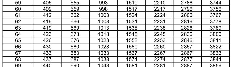
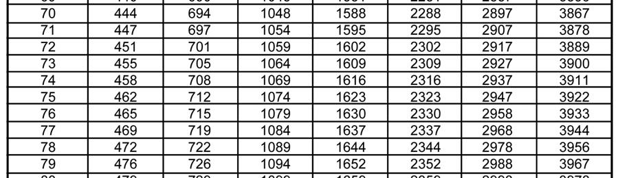
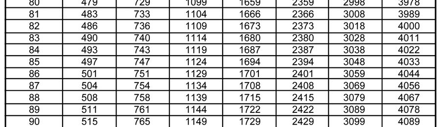
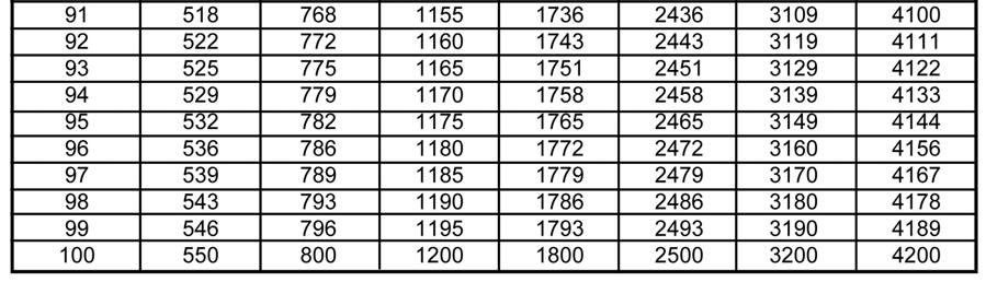
7 Table 2 Page 7
 The EVO/ECM-VCU features a 4 digit LED numerical display to allow easy reading in dark spaces. Watch the display and set the flow index with a screwdriver adjust.")
8 Visual Control Unit (VCU) The EVO/ECM-VCU control allows accurate manual adjustment and monitor of fans using General Electric s ECM Motor. (See figure 2) The EVO/ECM-VCU features a 4 digit LED numerical display to allow easy reading in dark spaces. Watch the display and set the flow index with a screwdriver adjust. Twenty seconds later, the display shows the motor RPM. Then, the display periodically alternates between the flow index and motor RPM. The EVO/ECM-VCU may also be used where automation systems only turn the fan on or off. Front of VCU Figure 2 Back of VCU control unit. Specifications Power NEC Class II Only 24 Vac ± 20% 50/60 Hz 4 W, 6 VA Flow Index Adjustment 270 rotation F Off RPM RPM ± 2% Outputs Go & Vspd ECM 2.3 Stability Operating Connections ma Set for Vspd Operation Set Status Flag (7) to RPM Thermal >0.01 %/ o F 0 o F to 130 o F (-18 o C to 55 o C) Environment 10-80% Rh 1/4 Tabs Page 8
 The on/off signal is provided at a 24V input. Another option is to turn the motor on/off with a 0-1V signal and to use the 2-10V for speed control.")
9 Automatic Control Unit (ACU+) If digital controls are being used on the project it is possible to control the speed of the ECM motor with a 0-10V control signal using the EVO ACU+ unit. (See figure 3) The on/off signal is provided at a 24V input. Another option is to turn the motor on/off with a 0-1V signal and to use the 2-10V for speed control. The EVO/ECM-ACU+ allows remote adjustment of the output from 0% to 100% of the programmed control range. A LED on the control continuously flashes out the flow index (percent of the programmed control range), so instruments are not required to read the value. The "P" version provides ON/OFF control by switching the motor's "GO" control when the input signal drops below the 2 volt (4 ma) operating point. The green LED continuously indicates the flow index. After a pause, the LED flashes out the tens digit, then the units digit of a number (percent) between 1 and 99. Two extra long flashes indicate a flow index of 0%. Long flashes represent the tens digit, and short flashes represent the units digit. A flow index of 23%, flashes two longs and three shorts. Control Test Procedure Warning: These tests are to be performed by qualified personnel who are familiar with the CARNES VAV box, where the EVO/ECM, series control and connected motor is installed. All mechanical, electrical and other applicable safety practices must be observed when performing these tests. While the EVO/ECM series controls are low voltage devices, they are often installed Page 9


10 in or near high voltage cabinets and wiring. And they are connected to electrically isolated connections on the ECM motor. Wiring and device faults can occur. Always test for high voltage before starting these tests! High Voltage Fault Test- Perform this test in addition to all tests and practices prescribed by the equipment manufacturer and your professional training. 1. Remove the VAV box control cover to gain access to the component side of the EVO/ECM series control. Leave everything connected. 2. If you removed power to gain access, re-power the equipment as necessary to troubleshoot the equipment. 3. Set the multi-meter to measure AC Volts. 4. Connect the BLACK lead to electrical earth. 5. Touch the RED lead to the EVO/ECM series connection marked 24VAC. The meter should read about 30 volts AC. If the meter reads a voltage above 48 volts AC immediately disconnect the VAV box. There is a high voltage fault somewhere in the system. 6. Touch the RED lead to the other connectors on the board. If the meter reads a voltage above 48 Volts AC, immediately disconnect the VAV box. There is a high voltage fault somewhere in the system. 7. Touch the RED lead to the metal wire grippers (top of connectors) for each of the 4 motor wires. (See Figure 2) If the meter reads a voltage above 48 Volts AC, immediately disconnect the machine. There is a high voltage fault somewhere in the system. Motor Connection Figure 2 White Motor On/Off 0-24V Black Tachometer Green Common Red Speed 0 min speed, 22 VDC max. speed Figure 3 A quick test: If the motor is not running and you want to determine if the EVO/ECM series control is calling for the motor to run, just measure the DC voltage between the Green and White wires on the motor control cable. If this voltage is greater than 10VDC, the motor should be running. If you have an instance where the motor stops intermittently, and it restarts when power is removed then restored, perform this test before removing power. It will tell you if the intermittent part is the EVO/ECM series control. Page 10
11 Trouble Shooting Guide Problem: The ECM motor will not run. 1. Check to make sure the power and control cables are securely fastened to both the ECM motor. Check the control connection to make sure it is secure. 2. Verify there is power to the unit. 3. Set the multi-meter to read 24VDC. 4. Touch the black lead to the motor 0n/Off (White) wire on the 4 pin motor connector. 5. Touch the red lead to the Motor On/Off (White) wire on the 4 pin motor connector. 6. If the DC voltage is 22VDC, the motor should run. 7. If the motor does not run, the cable may be defective. 8. Go to the control connector on the motor. 9. Insert the black meter lead into the connector shell hole containing the single green wire (See figure 3). 10. Insert the red meter lead into the connector shell hole containing the white wire. The DC voltage should be 22VDC. If it is not, the cable is defective. If the voltage is greater than 10VDC and motor does not run, contact CARNES CO. for further instructions. Problem: The motor runs but the speed does not change. 1. Start the motor running. 2. Set the multi-meter to read 24 VDC. 3. Touch the black lead to the common (Green) wire on the 4 pin motor connector. 4. Touch the red lead to the speed (RED) wire on the 4 pin motor connector. 5. Set the EVO/ECM series controller to full speed. 6. The DC voltage should be equal to the voltage on the white wire (24VDC). The motor should run at full speed. 7. If the motor does not run at full speed, the cable may be defective. 8. Go to the control connector on the motor. 9. Insert the black meter lead into the connector shell hole containing the single green wire. 10.Insert the red meter lead into the connector shell hole containing the RED wire. The DC voltage should equal the voltage on the white wire (22VDC). If it is not the control cable is defective. If the voltage is 22VDC and the motor does not run at full speed, contact CARNES CO. Page 11
12 Problem: The VAV box does not run with in the expected speed range. 1. Verify the variable speed control is working correctly. 2. Verify the correct unit is installed in the space. 3. Contact CARNES CO. Problem: The Automation System can not turn the motor off. 1. Turn the ECM motor off using the Automation System. 2. Touch the black lead to the common (Green) wire on the 4 pin motor connector. 3. Touch the red lead to the Tachometer (Black) wire on the 4 pin motor connector. 4. The DC voltage should be less than 3Vdc. 5. If the voltage is too high, the Automation Control is leaking current through its On/Off switching device. Problem: The speed control does not provide the RPM. Set the multi-meter to read 5Vdc. 1. Touch the black lead to the common (Green) wire on the 4 pin motor connector. 2. Touch the red lead to the Tachometer (Black) wire on the 4 pin motor connector. 3. You should read about 5Vdc. 4. Go to the control connector on the motor. 5. Insert the black meter lead into the connector shell hole containing the single green wire. 6. Insert the red meter lead into the connector shell hole containing the Black wire. The DC voltage should about 5Vdc. If it is not, the control cable is defective. Swap the EVO/ECM series control with a known good control to determine if the problem is with the EVO/ECM series control. If the problem persists, contact CARNES CO. for further details. Page 12


13 READ AND SAVE THESE INSTRUCTIONS INSTALLATION and OPERATION MANUAL FOR FAN POWERED TERMINAL UNITS CARNES COMPANY, 448 S. Main St., P.O. Box , Verona, WI Phone: 608/ Fax: 608/ CONSTANT VOLUME (Series) MODEL AC INTERMITTENT VOLUME (Parallel) MODEL AS COPYRIGHT 2010 SUPERSEDES B C, Page 1 All Rights Reserved
14 CAUTION: Completely Read All Instructions Prior To Attempting To Assemble, Install, Operate, Or Repair This Product! INSPECT UNIT UNPACKING AND INSPECTION 1. Open shipping carton or crate and check for concealed shipping damage. Report damage immediately to the carrier that delivered the shipment. 2. Inspect the unit for loose or missing components. 3. Optional accessories may be packed within the unit or in the same shipping carton or crate. INSTALLATION CAUTION: This Product Includes Vibration Producing Components. When Supporting Or Suspending Units, Use Good Industry Practice and Materials Suitable For Vibration Producing Equipment. GENERAL 1. Units are to be supported in a horizontal and level position. For convenience, it is suggested that units be installed prior to installation of the ceiling tile grid system. 2. Sufficient working space must be provided as per paragraph of N. E. C. 3. Allow sufficient space for the removal of air filters and for the efficient flow of air into the secondary air inlet. 4. Avoid abrupt transitions or duct turns at the inlet of the unit that would alter the inlet cross-sectional area. 5. It is preferred that the installer attempt to obtain a minimum of three (3) inlet diameters of straight duct ahead of the terminal unit inlet to achieve optimum control accuracy. DUCT CONNECTIONS 1. Units are provided with either slip and drive or flanged discharge duct connections depending upon model type. 2. It is suggested that discharge ductwork be lined with a minimum of 1/2 thick, 1-1/2 lb. density fiberglass insulation with an erosion resistant surface in accordance with NFPA 90A (non-residential type air conditioning and ventilating systems) to provide both thermal and acoustical insulation. 3. Sealing of ductwork to preclude air leaks should be done according to the job specifications. 4. It is recommended that units be supported from underneath using trapeze hangers and vibration isolators. Flexible connections are recommended for all connecting ductwork and electrical conduit to preclude the transmission of vibration noise. 5. It is recommended that flexible ductwork connected to the primary air inlet be secured using a compression band. Rigid duct should be slipped over the unit inlet, secured in place with sheet metal screws, and sealed according to the job specifications. ELECTRICAL INSTALLATION CAUTION: All Sources Of Supply Power Must Be Disconnected Before Working On This Equipment. More Than One Disconnect May Be Required To De-Energize Equipment. 1. Follow the wiring/piping diagram found on the inside of the fan unit control enclosure cover. 2. Supply connections must be made using wires rated for 75 O C minimum. DO NO USE ALUMINUM CONDUCTORS. 3. If supply connections are for 250 volts or greater, all wiring must be insulated for 600V. FORM C, Page 2
15 4. Size supply conductors for 125% of rated combined load (fan motor FLA + heater current). For electric heater use: Single phase KW x 1000 Line Current = Voltage Three phase KW x 1000 Line Current = 1.73 x Voltage 5. The following table shows the maximum current for 75 C Copper wire in conduit. Values are based on the 1984 N.E.C. Table including note 8. COMBINED LOAD MAXIMUM MINIMUM WIRE SIZES UNIT AMPERAGE AWG/MCM conductors conductors If not supplied as part of this unit, install a line disconnect and fusing or a circuit breaker in accordance with N. E. C. 7. The following table shows the maximum over current rating for wire servicing unit. MAXIMUM MAXIMUM OVERCURRENT SUPPLY UNIT AMPERAGE RATING All field and factory made connections should be checked for tightness before operation. 9. The unit must be wired so as to provide a fan relay interlock to preclude heater operation unless air is flowing over the heater. An interlock is factory wired if heaters are factory attached. FAN UNIT CONTROLS (See Figure 1) The following is a list of components located in the fan unit control panel. The figure at the right is to aid in component identification. Not all components are required for every control option and unit type. 1. Air Flow Switch. (Constant Volume Units) 2. Control Transformer. (Electronic/DDC Units) 3. Fan Motor Capacitor(s). 4. SCR Fan Speed Control. 5. Fan Motor Relay. 6. Fan Motor Disconnect Switch. 7. Pressure/Electric Switch. (Pneumatic Units) 8. Ground Lug. Contact your local Carnes Representative for replacement parts. CAUTION: 7 8 Severe Electrical Shock May Occur. Disconnect All Sources Of Supply Power Before Working On This Equipment. More Than One Disconnect May Be Required To De-Energize Equipment For Servicing FAN UNIT CONTROL PANEL Figure 1 FORM C, Page 3
16 BALANCING AND MAINTENANCE DANGER: Severe Electrical Shock May Occur. Disconnect All Sources Of Supply Power Before Working On This Equipment. More Than One Disconnect May Be Required To De-Energize Equipment For Servicing. SETTING SECONDARY (HEATING) AIR FLOW CONSTANT VOLUME (AC UNITS) 1. Adjust room thermostat to call for full cool. (Damper should open to the maximum CFM setting of the controller). 2. Remove secondary air filter if provided. 3. Tape a piece of cardboard onto the secondary air inlet. Size the cardboard 1/2 less than the height and 1/2 less than the width of the secondary inlet opening allow it to swing freely when taped in place. (Figure 2) 4. Adjust fan speed control (SCR) until the cardboard taped onto the secondary inlet hangs vertically indicating a balance between primary inlet air and discharge air CFM. 5. Remove the cardboard from secondary inlet. Replace filter if provided. 6. Fan CFM MUST NOT BE LESS than the maximum cooling CFM. Overloading the fan could cause motor damage and primary air to be forced out of the secondary inlet. INTERMITTENT VOLUME (AS UNITS) 1. Adjust room thermostat to call for full heat. (Damper should close to minimum CFM setting on the controller). 2. Adjust fan speed control (SCR) to design CFM as measured at the diffusers. ROUTINE MAINTENANCE (To be done at least once a year) 1. Check all field and factory made electrical and pneumatic connections for tightness. 2. Clean all air filters. Throw-away air filters may be ordered through your local Carnes Representative. Aluminum mesh air filters may be washed in warm soapy water. 3. Check compressed air supply for clean, dry and oil free compressed air. Figure 2 REMOVE (6) KEPS NUTS FROM MOUNTING ANGLE STUDS TAPE CARDBOARD OVER SECONDARY AIR INLET ALLOW TO SWING FREELY Figure 3 FAN/MOTOR REMOVAL REMOVE ACCESS PANEL SLIDE FAN/MOTOR TOWARD FRONT OF UNIT AND DOWN 4. Fan motors are permanently lubricated not requiring annual service. If a fan wheel becomes out of balance due to dust or debris or if the fan motor should need replacing, follow the procedure outlined below. 1. Remove screws holding access panel in place. 2. Remove keps nuts from the mounting angle studs located on either side of the fan housing. (See Figure 3) 3. Disconnect fan motor wires from inside of the fan unit control panel. 4. Slide the fan/motor sub-assembly out through the access opening. 5. Reverse procedure for re-installation. COMPANY 448 South Main Street P. O. Box Verona, WI Phone: 608/ Fax: 608/ carnes@carnes.com FORM C, Page 4
INSTALLATION & OPERATION MANUAL. Fan Powered Terminals VAV TERMINALS. Redefine your comfort zone.
 INSTALLATION & OPERATION MANUAL Fan Powered Terminals VAV TERMINALS IOM FAN POWERED TERMINALS Receiving Inspection After unpacking the terminal, check it for shipping damage. If any shipping damage is
ATU PRODUCT CATALOG AIR TERMINAL UNITS FCI-600 CONSTANT VOLUME FAN TERMINAL UNIT Metal Industries, Inc.
 ATU PRODUCT CATALOG AIR TERMINAL UNITS FCI-600 CONSTANT VOLUME FAN TERMINAL UNIT 15 Metal Industries, Inc. BENEFITS: Fan powered terminals are typically used for heating and cooling of perimeter zones.
FAN POWERED TERMINAL UNITS
 Benefits: Fan powered terminals are typically used for heating and cooling of perimeter zones. Operating cost savings can be achieved through the use of waste heat recovery from the ceiling plenum and
FAN POWERED TERMINAL UNITS
 Benefits: Fan powered terminals are typically used for heating and cooling of perimeter zones. Operating cost savings can be achieved through the use of waste heat recovery from the ceiling plenum and
University of Delaware
 SECTION 23 36 00 _ SUMMARY PART 1 GENERAL 1.1 SUMMARY A. Section Includes: 1. Constant/Variable volume supply terminal units. 2. Fan powered terminal units. 3. Exhaust valves B. Related Sections: Section
ECM-MSPD. Installation, Operation, and Maintenance Manual
 ECM-MSPD Installation, Operation, and Maintenance Manual READ AND SAVE THESE INSTRUCTIONS The purpose of this manual is to aid in the proper installation and operation of fans manufactured by S&P. These
Achieve Up To 200% Greater Efficiency And Better Air Flow Performance With GE ECM Technology
 Achieve Up To 200% Greater Efficiency And Better Air Flow Performance With GE ECM Technology GE ECM 2.3 ECM X13 What's an ECM? The highest efficiency motor there is! essentially a DC Motor Without mechanical
SECTION AIR TERMINAL UNITS
 SECTION 23 36 00 AIR TERMINAL UNITS PART 1 - GENERAL 1.1 SUMMARY A. Section includes constant volume terminal units, variable volume terminal units, dual duct terminal units, fan powered terminal units,
Motor. Document # Vari-Green Motor and Controls. Table of Contents. Features, Operation, Wiring and Troubleshooting
 Document #473681 Vari-Green Motor and Controls Installation, Operation and Maintenance Manual Please read and save these instructions for future reference. Read carefully before attempting to assemble,
Electric Furnace KF/KFS Series
 Electric Furnace KF/KFS Series KF/KFS 20 20 1 A B C D A: Series B: 20-208V 24-240V 48-480V C: Kilowatts D: 1 or 3-phase Heavy duty open-coil element Direct drive motor Up to 3-speed motor Standard 24 Volt
Fan Powered Low Profile Variable Volume Terminal Units
 MANUAL INSTALLATION Fan Powered Low Profile Variable Volume Terminal Units FEVLP / FPVLP / FDVLP Series v001 Issue Date: 07/19/16 07/19/16 Price Industries Limited. All rights reserved. TABLE OF CONTENTS
MANUAL TROUBLESHOOTING. ECM Motor. ECM / ECM-DX Series. v100 Issue Date: 08/15/ Price Industries Limited. All rights reserved.
 MANUAL ECM Motor ECM / ECM-DX Series v100 Issue Date: 08/15/17 2017 Price Industries Limited. All rights reserved. ECM MOTOR TABLE OF CONTENTS ECM Motor Background...1 ECM Motor Power and Control Connectors...2
MODELS TSX AND TSX-S SINGLE DUCT ROUND AIR TERMINALS
 MODELS TSX AND TSX-S SINGLE DUCT ROUND AIR TERMINALS INSTALLATION OPERATION & MAINTENANCE New Release Form 130.13-NOM4 (908) In conjunction with the use of these instructions, obtain and refer to the construction,
SECTION 4 ELECTRIC MOTORS UNIT 17: TYPES OF ELECTRIC MOTORS UNIT OBJECTIVES UNIT OBJECTIVES 3/21/2012
 SECTION 4 ELECTRIC MOTORS UNIT 17: TYPES OF ELECTRIC MOTORS UNIT OBJECTIVES After studying this unit, the reader should be able to Describe the different types of open single-phase motors used to drive
I Fan Powered Terminal Unit
 I Fan Powered Terminal Unit VARIABLE VOLUME PARALLEL FLOW Fan Powered Terminal Unit Variable volume parallel flow Product Overview Variable Volume/Parallel Flow Fan Powered Terminal Units Honeywell parallel
FAN TERMINAL UNITS Constant Volume (Series Flow), Standard Design
, Standard Design") FAN TERAL UNITS Constant Volume (Series Flow), Standard Design Models ACF w/o Coil ACW w/hot Water Coil ACE w/electric Coil The Carnes constant volume fan terminal unit provides constant air volume to
FAN TERAL UNITS Constant Volume (Series Flow), Standard Design Models ACF w/o Coil ACW w/hot Water Coil ACE w/electric Coil The Carnes constant volume fan terminal unit provides constant air volume to
MODELS SGX AND SSX SINGLE DUCT ROUND AIR TERMINALS
 BY JOHNSON CONTROLS INSTALLATION OPERATION & MAINTENANCE MODELS SGX AND SSX SINGLE DUCT ROUND AIR TERMINALS New Release Form ET130.13-NOM4 (908) In conjunction with the use of these instructions, obtain
SINGLE DUCT TERMINAL UNITS
 www.igcaire.com SINGLE DUCT TERMINAL UNITS Direct Digital Control, Pressure Independent FEATURES 22 Gauge Galvanized Steel Casing Construction with a 20 Gauge Casing Option that Provides Strength and Product
High Frequency SineWave Guardian TM
 High Frequency SineWave Guardian TM 380V 480V INSTALLATION GUIDE FORM: SHF-IG-E REL. January 2018 REV. 002 2018 MTE Corporation High Voltage! Only a qualified electrician can carry out the electrical installation
MANUAL INSTALLATION. Venturi FX. VFX Series. v100 Issue Date: 11/22/ Price Industries Limited. All rights reserved.
 MANUAL INSTALLATION Venturi FX VFX Series v100 Issue Date: 11/22/16 2016 Price Industries Limited. All rights reserved. TABLE OF CONTENTS Product Overview Safety Precautions... 1 Caution to Contractors...1
Direct Gas-Fired Heating
 Direct Gas-Fired Heating Model DG 800 to 15,000 cfm Up to 1,600,000 BTU/hr Optional Evaporative Cooling January 2005 PRODUCT FEATURES Model DG Direct Gas-Fired Make-Up Air Unit The Greenheck model DG is
Installation, Operation and Maintenance Manual
 Document 47681 Vari-Green Motor and Controls Installation, Operation and Maintenance Manual Please read and save these instructions for future reference. Read carefully before attempting to assemble, install,
FAN POWERED SERIES FCI-600 CONSTANT VOLUME FAN TERMINAL UNIT SPECIFIABLE FEATURES
 FAN TERMINAL UNIT SPECIFIABLE FEATURES Galvanized steel casing, mechanically sealed for low leakage construction NEMA TYPE 1 rated hinged control enclosure with standoff to prevent penetration of casing
Evolution. ECM Motor. T Control CONTROLS INC. EVO /ECM-DTC16. Differential Temperature Control. Specifications. Applications
 T Control CONTROLS INC. EVO /ECM-DTC16 Differential Temperature Control The EVO/ECM-DTC16 sets the ECM motor speed depending on the temperature difference measured by two temperature sensors. The DTC16
Daikin McQuay. VAV Air Terminal Unit MQ FCI6, FVI5, THI5. Replacement Parts List No Revision J 07/2017
 Replacement Parts List No. 700020000 Revision J 07/2017 Daikin McQuay VAV Air Terminal Unit MQ FCI6, FVI5, THI5 To find your Daikin Applied parts distributor, call 1-800-377-2787 or visit www.daikinapplied.com
B. Base occupied space sound level estimates on ARI 885. C. Terminal heating coils shall conform to ARI 410.
 PART 1 - GENERAL 1.01 Purpose: A. This standard is intended to provide useful information to the Professional Service Provider (PSP) to establish a basis of design. The responsibility of the engineer is
SineWave Guardian TM 380V 600V INSTALLATION GUIDE. Quick Reference. ❶ How to Install Pages 6 17 ❷ Startup/Troubleshooting Pages WARNING
 SineWave Guardian TM 380V 600V INSTALLATION GUIDE FORM: SWG-IG-E REL. October 2018 REV. 003 2018 MTE Corporation High Voltage! Only a qualified electrician can carry out the electrical installation of
Installation, Operation and Maintenance Manual
 Document 473681 Vari-Green Motor and Controls Installation, Operation and Maintenance Manual Please read and save these instructions for future reference. Read carefully before attempting to assemble,
Variable Air Volume Dampers
 OVAV 2000 SERIES OPTIMA VAV DAMPERS Overview OPTIMA make Variable Air Volume (OVAV) box is a part of an Air Conditioning system. It is located inside the duct work. VAV Dampers are designed to control
INSTALLATION INSTRUCTIONS
 MiniCOREVentilator ENERGY RECOVERY CORE INSTALLATION INSTRUCTIONS MC500-1ERV JANUARY 10, 2018 SUPERSEDES: NONE INSTALLATION INSTRUCTIONS FOR MINICORE VENTILATOR (MCV) WITH FACTORY INSTALLED OPTIONS USED
Product Data. Features/Benefits. 45J,M,K,N,Q,R Standard, Quiet, and Low Profile Fan Powered Variable Air Volume Terminals
 Product Data 5J,M,K,N,Q,R Standard, Quiet, and Low Profile Fan Powered Variable Air Volume Terminals 90 to 3900 Cfm Series Fan Box 5J,K,Q Parallel Fan Box 5M,N,R 5J,M 5K,N 5Q,R The 5J,M,K,N,Q,R units were
Matrix APAX. 380V-415V 50Hz TECHNICAL REFERENCE MANUAL
 Matrix APAX 380V-415V 50Hz TECHNICAL REFERENCE MANUAL WARNING High Voltage! Only a qualified electrician can carry out the electrical installation of this filter. Quick Reference ❶ Performance Data Pages
SDL Single-Duct, Low-Height, VAV Terminals
 SDL -Duct, Low-Height, VAV Terminals SDL -Duct, VAV Terminals: Fit more comfort in less space Owners SDL terminals offer the typical benefits provided by single-duct units, while performing at extremely
TSS Single-Duct VAV Terminals
 TSS Single-Duct VAV Terminals Model TSS construction features Standard Construction Mechanical-lock construction ensures lowest possible casing leakage Roll-formed inlet collar with integral stiffening
Installation, Operation and Maintenance Manual
 Document 473681 Vari-Green Motor and Controls Installation, Operation and Maintenance Manual Please read and save these instructions for future reference. Read carefully before attempting to assemble,
MODEL SCA Installation and Operation Manual Important:
 MODEL SCA Installation and Operation Manual Important: This manual contains specific cautionary statements relative to worker safety. Read this manual thoroughly and follow as directed. It is impossible
Electronically Commutated Motor Wiring Manual
 Electronically Commutated Motor Wiring Manual Table of Contents Safety Considerations 3 Application Guide 4, 5, 6, 7, 8 Operational Characteristics 9, 10, 11, 12 Diagnostics, Maintenance & Warranty 13
Product Data. Features/Benefits. 45J,M,K,N,Q,R Standard, Quiet, and Low Profile Fan Powered Variable Air Volume Terminals.
 Product Data 45J,M,K,N,Q,R Standard, Quiet, and Low Profile Fan Powered Variable Air Volume Terminals 90 to 3900 Cfm 45J,M 45K,N 45Q,R The 45J,M,K,N,Q,R units were designed to maintain accurate temperatures
Installation, Operation and Maintenance Manual
 Document 47681 Vari-Green Motor and Controls Installation, Operation and Maintenance Manual Please read and save these instructions for future reference. Read carefully before attempting to assemble, install,
Product Data. AXIS 45X, 45U, 42K, 35BF Access Floor Terminal Units for Variable Air Volume Systems
 Product Data AXIS 45X, 45U, 42K, 35BF Access Floor Terminal Units for Variable Air Volume Systems 45UC 35BF-R 42KC 45XC 35BF-D Features/Benefits Access Floor Systems can provide flexibility and economic
R820 REV2 SERIES SCR POWER CONTROLS NOVEMBER 2017
 R80 REV SERIES SCR POWER CONTROLS NOVEMBER 017 Product overview The Viconics R80 series SCR power controls are designed for cost effective, precise modulation of electric loads for most electric heating
Installation Instructions
 Quick-Mount Visual Instructions for Mechanical Installation Quick-Mount Visual Instructions 1. Rotate the damper to its failsafe position. If the shaft rotates counterclockwise, mount the CCW side of the
Variable Air Volume (VAV) Pressure Independent Control
 Pressure Independent Control") VAV Terminal Units Asli Variable Air Volume (Vav) Terminal Units are volume flow rate controller for supply air on variable air volume system. These units are designed to control the airflow rate of conditioned
VAV Terminal Units Asli Variable Air Volume (Vav) Terminal Units are volume flow rate controller for supply air on variable air volume system. These units are designed to control the airflow rate of conditioned
Product Data. Features/Benefits. 35K Bypass Terminal. 110 to 4400 cfm
 Product Data 35K Bypass Terminal 110 to 4400 cfm Carrier s 35K Series bypass terminals offer: 20-gage, galvanized steel casing construction 1/2-in. thick, dual density fiberglass insulation meeting NFPA
Owner's/Installation Manual
 Owner's/Installation Manual Power Management Module (PMM) and Starter Kit NOTE: The starter kit must be purchased and installed prior to individual PMM usage. Model Numbers: 00686-0 PMM 00699-0 PMM WITH
Safety & Installation Instructions
 Model 8120A & 8126A Digital Ventilation Controller Safety & Installation Instructions READ AND SAVE THESE INSTRUCTIONS Table of contents Safety Instructions... 3 Specifications... 4 Overview... 4 Mounting
INSTALLATION, OPERATION AND MAINTENANCE MANUAL WALL EXHAUST FANS BELT DRIVE XBL FANS
 INSTALLATION, OPERATION AND MAINTENANCE MANUAL WALL EXHAUST FANS BELT DRIVE XBL FANS The purpose of this manual is to aid in the proper installation and operation of the fans. These instructions are intended
www. ElectricalPartManuals. com Instruction Bulletin ALTIVAR FLEX58 TRX Adjustable Speed Chassis Drive Controllers Installation Guide
 Instruction Bulletin ALTIVAR FLEX58 TRX Adjustable Speed Chassis Drive Controllers Installation Guide Retain for future use. 30072-450-47A July 2002 Raleigh, NC, USA HAZARDOUS VOLTAGE Read and understand
NJK Precision Product NJK-02 Sensor Installation Guide
 Precision -02 Sensor 2017 Product Line Precision Product Table of Contents Precision Company Overview - Page 2-02 Installation Guidelines - Page 3-02 Recommended Installations - Page 5-02 Non-Recommended
Installation Instructions
 Quick-Mount Visual Instructions for Quick-Mount Visual Instructions 1. Rotate the damper to its failsafe position. If the shaft rotates counterclockwise, mount the CCW side of the actuator out. If it rotates
REFERENCE MANUAL FORM: MX-TRM-E REL REV MTE
 Matrix APAX 380V-415V 50Hz TECHNICAL REFERENCE MANUAL FORM: MX-TRM-E REL. September 2014 REV. 002 2014 MTE Corporation WARNING High Voltage! Only a qualified electrician can carry out the electrical installation
TROUBLESHOOTING GUIDE FOR HEAT PUMP BOOSTERS MODELS: HPB11, HPB15, & HPB22
 V3 TROUBLESHOOTING GUIDE FOR HEAT PUMP BOOSTERS MODELS: HPB11, HPB15, & HPB22 PREFACE This guide contains instructions for troubleshooting the Steffes Corporation room heating units: Models HPB 11, HPB
12 CB30M SERIES UNITS INCLUDING ECB29 ELECTRIC HEAT
 Service Literature Corp. 9711 L7 CB29M CB30M ELITE 10 CB29M and ELITE 12 CB30M SERIES UNITS INCLUDING ECB29 The Elite 10 CB29M and Elite 12 CB30M are high efficiency blower coils. Several models are available
B BASIC HEAT TREATMENT CONSOLE
 Maritime Stress PO Box 2898, 30 Estates Road Dartmouth, NS, B2W 4Y2, Canada Toll Free: 1-877-468-1781 Phone: (902) 468-7873 Fax: (902) 468-2304 Website: E-mail: info@maritimestress.com OPERATION MANUAL
AFM500X Automatic Flashing Module
 AFM500X Automatic Flashing Module The Power-Tronics AFM500X Automatic Flashing Module is a convenient and compact optional build up module for all Power-Tronics UVR and XR series Universal Voltage Regulators.
The ECM Textbook.
 Table of Contents - Overview of ECM Technology - Indoor Blower Motors o Variable Speed ECM o Constant Torque ECM The ECM Textbook www.thedealertoolbox.com About the Company When Regal Beloit acquired General
Installation Instructions Electric Heaters 5 20 kw
 Small Packaged Products 2 to 5 Tons Accessory Electric Heaters Cancels: IIK 564A-24-2 IIK 564A-24- -02 Installation Instructions Electric Heaters 5 20 kw NOTE: Read the entire instruction manual before
The ECM Textbook ECM. Table of Contents. - Overview of ECM Technology. - Indoor Blower Motors o Variable Speed ECM o Constant Torque ECM
 The ECM Textbook Table of Contents Overview of ECM Technology Indoor Blower Motors o Variable Speed ECM o Constant Torque ECM ECM PSC 2007 GE ECM by REGALBELOIT ECM Textbook Rev 1.4 This material has been
CALTRAP INSTALLATION AND OPERATIONS MANUAL
 INSTALLATION AND OPERATIONS MANUAL NOTE Please read this entire installation and operations manual before energizing the. Safety Considerations: Installing and servicing capacitor equipment can be hazardous.
INSTALLATION VARIABLE FREQUENCY DRIVE THREE PHASE ALX SERIES SPUN ALUMINUM EXHAUSTERS
 SPUN ALUMINUM EXHAUSTER OPERATION INSTRUCTIONS AND PARTS MANUAL READ AND SAVE THESE INSTRUCTIONS The purpose of this manual is to aid in the proper installation and operation of the blowers. These instructions
Electronic Ballast EVG 2000-T
 Electronic Ballast EVG 2000-T Operating Manual Table of contents 1 Description 1.1 Advantages of this ballast... 3 1.2 Functional principle... 3 1.3 Energization... 4 1.4 Visualization... 5 1.5 Indications
INSTRUCTION MANUAL. Type SWF. Sine Wave Filters 480 Volts, 60Hz. Page 1 of 14. April 15, 2010: updated capacitor UL File number)
") POWER QUALITY INSTRUCTION MANUAL Type SWF Sine Wave Filters 480 Volts, 60Hz April 15, 2010: updated capacitor UL File number) Page 1 of 14 Contents 1. Introduction & SAFETY 2. Theory of operation 3. Advantage
POWER QUALITY INSTRUCTION MANUAL Type SWF Sine Wave Filters 480 Volts, 60Hz April 15, 2010: updated capacitor UL File number) Page 1 of 14 Contents 1. Introduction & SAFETY 2. Theory of operation 3. Advantage
Installation and Maintenance Instructions. World Leader in Modular Torque Limiters. PTM-4 Load Monitor
 World Leader in Modular Torque Limiters Installation and Maintenance Instructions PTM-4 Load Monitor 1304 Twin Oaks Street Wichita Falls, Texas 76302 (940) 723-7800 Fax: (940) 723-7888 E-mail: sales@brunelcorp.com
User s Manual. ACS550-CC Packaged Drive with Bypass Supplement for ACS550-01/U1 Drives User s Manual
 User s Manual ACS550-CC Packaged Drive with Bypass Supplement for ACS550-01/U1 Drives User s Manual ii ACS550-CC Packaged Drive with Bypass ACS550 Drive Manuals GENERAL MANUALS ACS550-01/U1 Drives User's
RE-PR3-E-86&105 3-Phase Panel Mount 86 and 105kW
 Page 1 of 6 3-Phase Panel Mount 86 and 105kW Features: Benefits: 0-10Vdc, 0-5Vdc, 4-20mA or manual via potentiometer control input Over temperature protection with auto reset Enclosed panel mounting Efficient
Valcom Failsafe Unit. 1620ESv2 SERIES. Operation and Maintenance Manual
 Valcom Failsafe Unit 1620ESv2 SERIES Operation and Maintenance Manual Table of Contents Section Title Page 1. - Introduction.. 2. - Unpacking the Failsafe unit. 3. - Installation 3.1 - Auto / Timed UPS
Q7RE Series Single Packaged Heat Pump, Single Phase
 TECHNICAL SPECIFICATIONS Q7RE Series Single Packaged Heat Pump, Single Phase 14 SEER, 8.0 HSPF 2 thru 5 Ton Units Cooling: 23,400 to 55,500 Btuh Heating: 21,800 to 56,000 Btuh The Q7 Series single packaged
Installation Instructions Electric Heaters 5 20 kw
 Small Packaged Products to 5 Tons Accessory Electric Heaters Cancels: IIK 564A--1 IIK 564A-- 11-01 Installation Instructions Electric Heaters 5 0 kw NOTE: Read the entire instruction manual before starting
PowerLogic High Density Metering System 4-Meter Enclosure Installation Guide
 PowerLogic High Density Metering System 4-Meter Enclosure Installation Guide 7002-0289-00 Instruction Bulletin HAZARD CATEGORIES AND SPECIAL SYMBOLS Read these instructions carefully and look at the equipment
OPERATING AND MAINTENANCE MANUAL. Primary Current Injection Test Set. 750ADM-H mk2
 OPERATING AND MAINTENANCE MANUAL Product: Type: Primary Current Injection Test Set 750ADM mk2 750ADM-H mk2 DESIGNED AND MANUFACTURED BY: T & R Test Equipment Limited 15-16 Woodbridge Meadows, Guildford,
AIR CLEANERS. Model MX 6000 OWNER S MANUAL CAUTION. Read complete instructions before operating. Please file for future reference.
 AIR CLEANERS Model MX 6000 OWNER S MANUAL CAUTION Read complete instructions before operating. Please file for future reference. MODEL MX 6000 SPECIFICATIONS Input Volts: 208-230/460 VAC, 60Hz, 3 Phase
User Manual. Solar Charge Controller 3KW
 User Manual Solar Charge Controller 3KW 1 CONTENTS 1 ABOUT THIS MANUAL... 3 1.1 Purpose... 3 1.2 Scope... 3 1.3 SAFETY INSTRUCTIONS... 3 2 INTRODUCTION... 4 2.1 Features... 4 2.2 Product Overview... 5
Fan Coil Unit (FCU) Fan Motor Control
 Fan Motor Control") Fan Coil Unit (FCU) Fan Motor Control Fan Relay Board 2 (FRBii) Installation, Operation, and Maintenance The Fan Relay Board assembly (FRBii) provides electronic control for the fan motor and various connections
Fan Coil Unit (FCU) Fan Motor Control Fan Relay Board 2 (FRBii) Installation, Operation, and Maintenance The Fan Relay Board assembly (FRBii) provides electronic control for the fan motor and various connections
Fan - Powered Terminal Unit Series Flow
 5/22/M/1 Fan - Powered Terminal Unit Series Flow Type TFP Trox (Malaysia) Sdn Bhd 20 Persiaran Bunga Tanjung 1 Senawang Land Industrial Park 70400 Seremban Negeri Sembilan Darul Khusus Malaysia Telephone
Electric Motor Controls BOMA Pre-Quiz
 Electric Motor Controls BOMA Pre-Quiz Name: 1. How does a U.P.S. (uninterruptable power supply) work? A. AC rectified to DC batteries then inverted to AC B. Batteries generate DC power C. Generator, batteries,
Installation and Operation Manual Underfloor Fan Powered Terminal Units Model Series: 38F and 38S
 Installation and Operation Manual Underfloor Fan Powered Terminal Units Model Series: 38F and 38S Receiving Inspection After unpacking the terminal unit, check it for shipping damage. If any shipping damage
ELITE SERIES R-410A Ready - Multi-Position
 PRODUCT SPECIFICATIONS AIR HANDLERS CBXM ELITE SERIES R-0A Ready - Multi-Position Bulletin No. 0 October 07 Supersedes June 0 Nominal Capacity -. to Tons Optional Electric Heat -. to 0 kw MODEL NUMBER
Coil Data Nominal Current MA Nominal VA Sealed Single Pole Normally Open (SPNO) White Rodgers Q
 White Rodgers Q") 14/03/08 A136 Relay - General Purpose 90-293Q Enclosed fan relays used for switching single or two speed fan motors, solenoids, relays, resistive loads, heating and cooling applications and general purpose
14/03/08 A136 Relay - General Purpose 90-293Q Enclosed fan relays used for switching single or two speed fan motors, solenoids, relays, resistive loads, heating and cooling applications and general purpose
ADVANCED PID TROUBLESHOOTING
 ADVANCED PID TROUBLESHOOTING August 29, 2016 A KEY POINT If the drive is telling you something via a Fault, then the problem is probably not the drive. The drive is recognizing a fault and telling you
Matrix AP 400V 690V INSTALLATION GUIDE. Quick Reference. ❶ How to Install Pages 6 20 ❷ Startup/Troubleshooting Pages WARNING
 Matrix AP 400V 690V INSTALLATION GUIDE FORM: MAP-IG-E REL. May 2017 REV. 002 2017 MTE Corporation WARNING High Voltage! Only a qualified electrician can carry out the electrical installation of this filter.
500-YVI PARALLEL FAN-POWERED AIR TERMINAL UNIT FORM EG3 (404)
") 500-YVI PARALLEL FAN-POWERED AIR TERMINAL UNIT Table of Contents Introduction...3 500-YVI Features...4-5 Dimensional Data...6-7 ARI Rating Points...8 Statement of Standard Test Conformity...8 Motor Amperage
500-YVI PARALLEL FAN-POWERED AIR TERMINAL UNIT Table of Contents Introduction...3 500-YVI Features...4-5 Dimensional Data...6-7 ARI Rating Points...8 Statement of Standard Test Conformity...8 Motor Amperage
User s Manual. ACH550-CC/CD Packaged Drive with Classic Bypass Supplement for ACH550-UH HVAC User s Manual
 User s Manual ACH550-CC/CD Packaged Drive with Classic Bypass Supplement for ACH550-UH HVAC User s Manual ii ACH550-CC/CD Packaged Drive with Classic Bypass ACH550 Drive Manuals GENERAL MANUALS ACH550-UH
MODEL ELC-12/40-CVM-D BATTERY CHARGER
 NATIONAL RAILWAY SUPPLY MODEL ELC-12/40-CVM-D BATTERY CHARGER Installing, Operating and Service Instructions for the ELC-12/40-CVM-D Solid State Charger PLEASE SAVE THESE IMPORTANT SAFETY AND OPERATING
INSTALLATION INSTRUCTIONS COMMERCIAL ROOM VENTILATORS WITH EXHAUST
 INSTALLATION INSTRUCTIONS COMMERCIAL ROOM VENTILATORS WITH EXHAUST MODEL CRVMP-5 For Use with Bard 3 through 5 Ton Wall Mount Air Conditioners and Heat Pumps Bard Manufacturing Company Bryan, Ohio 43506
NORTHWESTERN UNIVERSITY PROJECT NAME JOB # ISSUED: 03/29/2017
 SECTION 23 3600 - AIR TERMINAL DEVICES PART 1 - GENERAL 1.1 SUMMARY A. Section Includes: 1. Fan-powered air terminal units/devices. 2. Shut off air terminal units/devices. 3. Dual duct terminal units/devices.
Florham Park, NJ USA Call (ASCO) for sales or service
 for sales or service") Operator s Manual 7000 Series ATS Automatic Transfer Switches D design, 30 through 230 A DANGER is used in this manual to warn of a hazard situation which, if not avoided, will result in death or serious
Operator s Manual 7000 Series ATS Automatic Transfer Switches D design, 30 through 230 A DANGER is used in this manual to warn of a hazard situation which, if not avoided, will result in death or serious
ACC Series Power Conditioner OPERATION & INSTALLATION MANUAL
 ACC Series Power Conditioner OPERATION & INSTALLATION MANUAL PHASETEC digital power conditioners are designed to safely operate electrical equipment in the harshest power quality environments. With a wide
MERIT Series R-410A - Upflow / Horizontal - Variable Speed
 PRODUCT SPECIFICATIONS AIR HANDLERS CBX5UHV (-01) MERIT Series R-10A - Upflow / Horizontal - Variable Bulletin No. 10611 March 015 Supersedes November 01 MODEL NUMBER IDENTIFICATION CB X 5 UH V - 00-0
COOKSON OWNER S MANUAL
 COOKSON OWNER S MANUAL ELECTRIC CLUTCH RELEASE FOR TUBULAR MOTOR 3117(1) ECN 0951 BY RG 10/28/10 1 PATENT NO. 6,155,324 SPECIFICATIONS ELECTRICAL SPECIFICATIONS TUBULAR MOTOR FOR TUBULAR MOTOR ELECTRICAL
POWER FACTOR CORRECTION MOTOR LOAD (ML) FIXED CAPACITOR
 FIXED CAPACITOR") User s Manual for The POWER FACTOR CORRECTION MOTOR LOAD (ML) FIXED CAPACITOR 301 Gaddis Boulevard Dayton, Ohio 45403 U.S. Toll Free 866-261-1191 (937) 253-1191 Fax: (937) 253-1723 Web site: www.stacoenergy.com
User s Manual for The POWER FACTOR CORRECTION MOTOR LOAD (ML) FIXED CAPACITOR 301 Gaddis Boulevard Dayton, Ohio 45403 U.S. Toll Free 866-261-1191 (937) 253-1191 Fax: (937) 253-1723 Web site: www.stacoenergy.com
ZHA/ZHB SERIES WARNING
 Service Literature Corp. 09-L Revised 7-08 ZHA/ZHB SERIES, 4, 5 and 6 ton 0.6 to kw ZHA/ZHB06, 048, 060, 07 The ZHA/ZHB packaged electric heat pump units are available in standard cooling efficiency (06S,
MODEL ELC-12/60-D BATTERY CHARGER
 *32198* NATIONAL RAILWAY SUPPLY Installing, Operating and Service Instructions for the 12/60 Solid State Charger MODEL ELC-12/60-D BATTERY CHARGER PLEASE SAVE THESE IMPORTANT SAFETY AND OPERATING INSTRUCTIONS
Installation and Construction Notes for EVSE4
 Installation and Construction Notes for EVSE4 You need to read and understand this if you want to build an EVSE that will be safe and need to pass a building inspectors review. Before beginning this process
X100P Load Bank. Read all instructions before using the load bank. Contents
 X100P Load Bank Read all instructions before using the load bank Contents 1. Components... 3 Total Assembly... 3 2) Specifications... 4 a) X100P Load Bank... 4 3) Receiving... 4 4) Safety... 5 a) Grounding...
ERV ENERGY RECOVERY VENTILATOR 60 HZ. Indoor / Outdoor 500 to 10,000 cfm Capacity ERV I - D - D - P - 1 MODEL NUMBER IDENTIFICATION
 P R O D U C T S P E C I F I C AT I O N S I N D O O R A I R Q U A L I T Y ERV ENERGY RECOVERY VENTILATOR 60 HZ Bulletin No. 20245 March 200 Supersedes April 2009 Indoor / Outdoor 500 to 0,000 cfm Capacity
SECOND GENERATION Use this guide with unit serial number prefix beginning with BWF using Terra Power separator.
 Technical Information and Diagnostic Guide for SECOND GENERATION Use this guide with unit serial number prefix beginning with BWF using Terra Power separator. This guide will assist you in becoming more
Wiring diagrams on page 29 are for reference only. For detailed vehicle wiring refer to Navistar documents.
 1 10/2014 REV 7 !!Attention!! Before performing diagnostics: Wiring diagrams on page 29 are for reference only. For detailed vehicle wiring refer to Navistar documents. Check for Fault Codes using the
ELITE Series R-410A - Upflow / Horizontal
 PRODUCT SPECIFICATIONS AIR HANDLERS CBX7UH ELITE Series R-0A - Upflow / Horizontal Bulletin No. 08 March 0 Supersedes October 0 Nominal Capacity -. to Tons Optional Electric Heat -. to kw MODEL NUMBER
EVER EFFICIENT. EVER RELIABLE. EVER PROFITABLE.
 EVER EFFICIENT. EVER RELIABLE. EVER PROFITABLE. A Regal Brand EVERGREEN SOLUTIONS Powered by ECM Technology Upgrade/Replace PSC motors with Evergreen IM Residential/Light Commercial HVAC Systems Reduce
Users Manual. Defender 1 8.0KW to 14.0KW Online Emergency Lighting Inverter. Technical Manual # Revision B
 Users Manual Defender 1 8.0KW to 14.0KW Online Lighting Inverter Technical Manual #018-0102-01 Revision B Phone: 1.877.DSPM.POWER 1.877.377.6769 Fax: 909.930.3335 Website: www.dspmanufacturing.com E-Mail: