Brief Operating Description: Longer Motor Life Starts with a Switch
|
|
|
- Walter Dennis
- 5 years ago
- Views:
Transcription
1 Contents Brief Operation Description Application Design Features Models and Mounting Options SINPAC Switch Ordering and Identification Information Overview of Standard Product Offering Split Phase Motors PV Series for VAC Start Circuit ( typical max. motor hp) PV Series for VAC Start Circuit (1 typical max. motor hp) Start Motors CV Series for VAC Start Circuit ( typical max. motor hp) CV Series for VAC Start Circuit (5 typical max. motor hp) Start Motors Instant Reversing IR Series for VAC Start Circuit ( typical max. motor hp) Start/ Run Motors VR Series for VAC Start Circuit ( typical max. motor hp) VR Series for VAC Start Circuit (5 typical max. motor hp) Start and Start/ Run Motors CVR Series for VAC Start Circuit ( typical max. motor hp) CVR Series for VAC Start Circuit (10 typical max. motor hp) Installation Instructions for SINPAC Switches Wiring Diagrams Procedure for Checking SINPAC Switches Troubleshooting Guide Distributors of SINPAC Switch Worldwide Sales and Service Performance Parameters and Limited Warranty Brief Operating Description: Longer Motor Life Starts with a Switch For over 75 years, single-phase motors have utilized a mechanical centrifugal switch to switch the start circuit. Inherent characteristics of a mechanical device have made these switches prone to various problems, including tolerances, tolerance buildups, mechanical fatigue, vibration and a host of others that can lead to switch failures and/or performance inconsistency. Our challenge was to design a reliable solid-state switch to replace the mechanical switch and actuator mechanism that would duplicate the function of connecting and disconnecting the start circuit at particular speeds with the additional benefits of a solid-state device. After considerable research, we decided a successful electronic motor starting switch could be created by sensing the voltages present in the main and start windings. Until the rotor of a single-phase motor begins to rotate, there is no coupling between its start winding and main winding. When the rotor begins to turn, the main winding induces flux in the rotor, which then induces a voltage in the start winding. The voltage induced in the start winding is directly proportional to motor speed. In Stearns SINPAC Electronic Switches, the voltage across a motor s main winding and the voltage across its start winding are sampled and fed to a comparator. The logic circuitry is designed so that the electronic switch interrupts the start circuit current after the motor has accelerated to the speed at which cut out voltage is developed, generally 75 to 0% of synchronous motor speed. The logic circuitry then shuts down the switch s power stage, which consists of a triac or inverse parallel SCR s. This function is referred to as cut out. When the start circuit is disconnected, the main winding field then drives the motor s rotor to its running speed. If the motor encounters an overload, and the motor speed falls to approximately % of its synchronous speed, the SINPAC Switch automatically reconnects the motor s start circuit. This function is referred to as cut in. Cut in detection circuitry constantly monitors start winding voltage. When the motor s speed falls to the cut in point, the detection circuit causes the control logic to energize the SINPAC Switch s power output stage. The motor then goes through its normal startup procedure, with the start circuit being switched out at a motor speed approximately 75 to 0% of synchronous speed. SINPAC Switches are potted and completely sealed, making it impervious to dust, dirt and moisture. The unique speed sensing circuit provides a universal design which allows a few switches to work on most standard motor designs regardless of manufacturer. Acceptance by Motor Manufacturers US and foreign motor manufacturers have tested and retested the SINPAC Switch for reliability and quality. Today, many of these manufacturers have begun installing SINPAC Switches on their standard motor lines with more companies ready to make the changeover. UL Recognition Many SINPAC Switches have already been recognized under the Component Program of Underwriters Laboratories, Inc. (E-71). In addition, all switches have internal surge protection which is tested according to IEEE C Category A. CSA Certification LR-64. S
2 Applications Stearns SINPAC Switches are ideal for applications requiring reliable switching of the start circuit in singlephase motors. Mechanical switches are prone to various problems including mechanical fatigue, tolerances, tolerance build-ups and vibration which can lead to performance inconsistency. Electronic SINPAC Switches solve all those problems which reduce production downtime in hundreds of applications. Some of these applications are illustrated below: Some additional applications include: Grain Dryers Paint Sprayers Water Equipment Vacuum Pumps Power Tools Air Compressors Commercial Dryers Pressure Sprayers Commercial Washing Machines Vibrators Ice Makers Auger Drives Gas Pumps Door Openers Floor Washers Sump Pumps Bottle Washing Machines Diaphragm Pumps Floor Sanders Hermetic Motors Poultry Feeding Systems Rotary Compressors Fans, Blowers Grinding Machines Refrigeration Compressors Milking Machines Heat Pumps Winches Jet Pumps /60 Hz Submersible Pumps Hoists Food Processing Gate lifts Hoists Air compressors Door and partition systems Swimming pool pump motors Submersible pumps Vacuum pumps

3 Design Features Speed Sensitive SINPAC Switches duplicate mechanical switch performance. They cut out the start circuit at approximately 0% of synchronous speed*. This means no degradation in motor performance and no confusing and cumbersome time or current selection criteria to consider, since SINPAC Switches are not load sensitive. It also means there will be less stress on the starting capacitor due to over voltage. Restart Capability When motor speed drops below % of synchronous speed, the start circuit is reconnected to reinitiate starting torque. Accepted by Motor Manufacturers Stearns SINPAC Switches have been tested with favorable results and are available from most singlephase motor manufacturers. Transient Protection Transient protection tested per IEEE C Category A. Line Compensation No modifications or changes are required for line voltage variations. SINPAC Switches will operate in areas susceptible to brown-outs or low voltage due to long wiring runs. Electrically Protected Design SINPAC Switches are designed to filter out electrical noise, so there is no concern of random switch malfunctions. UL Recognition and CSA Certification Testing has been completed and approval has been obtained on most sizes and will be obtained on the balance of the product line. SINPAC Switches can be used with confidence in their safety and acceptance. Completely Solid-State With no moving parts, SINPAC Switches have no physical constraints to affect their operation. Can be used on new or existing motors. No wearing parts means high cycling. No shaft extension required. Not restricted by motor vibration or overspeed. No arcing contacts due to restart during motor coastdown. Universal Design SINPAC Switches will work on, 4, 6 or more pole motors of any manufacturer. This reduces motor manufacture and repair shop selection time and switch inventory. It also means that foreign and obsolete motors can be easily retrofitted with SINPAC Switches. Environmentally Protected SINPAC Switches are immune to moisture, dust, shock, vibration or overspeed. The switch will not limit motor performance due to environmental conditions. Stearns Reliability Years of experience in the motor industry, first with brakes and now with speed sensing switches, means you can depend on Stearns SINPAC Switches to solve switching problems. Unlimited Mounting Locations SINPAC Switches offer a variety of external and internal conduit box mountings and external endbell mountings. These mountings are not affected by the motor position (shaft up or shaft down). SINPAC Switches can also be mounted at locations remote from the motor. Reduced Installation Time Easy accessible terminals and mounting, reduce the amount of time required to install SINPAC Switches. Integral Design SINPAC Switches can reduce the length of the motor when designed as an integral part of the motor. *Contact factory for questions on specific switch/motor performance. S-795-


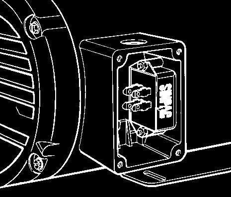

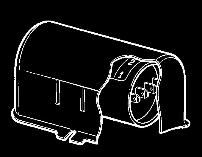
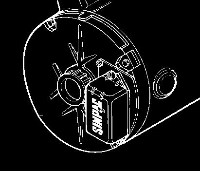

4 Models Style Style Style Style 17 Style Style Gasket (available for and Styles) Mounting Options 4
5 SINPAC Switch Ordering and Identification Information SINPAC Electronic Switch Numbering System CV-- Each stock electronic series switch is uniquely specified by an alphanumerical catalog number. For most standard SINPAC Electronic Switches, the catalog identifies a particular switch, including voltage, series, current rating, and cut out or cut in voltage. The first position indicates the start circuit voltage (blank equals volts and equals volts). The next characters specify the series or type of motor on which the switch should be used. The next numeric characters specify the maximum current which the switch can handle. The next numeric grouping specifies cut out voltage for capacitor start, capacitor start/capacitor run, and instant reversing switches and cut in CV voltage for the PV Switches. The Table shown on Page 6 provides information for selecting appropriate catalog number when ordering a Stearns electronic switch. For example, when ordering a capacitor start, amp switch with volt cut out, catalog number would be CV-- as follows: Start Winding Cut Out (Cut In PV) blank =, = Maximum Current Rating Series CVR = Start and Start/ Run Motors, PV = Split Phase Only, CV - Start Only, VR = Start/ Run Only, IR = Start Instant Reverse Each Stearns SINPAC Electronic Switch is uniquely specified by a - digit alphanumeric part number. For most standard SINPAC Electronic Switches, the last 10 positions identify the specific switch, including Electronics 6 = Switchpac (6 switches) 7 = SINPAC Switch 1 = PV Series - Split Phase Only = CV Series - Start Only = Made-To-Order (MTO)* 4 = CVR Series - Start and Start/ Run 5 = IR Series - Start Only 6 = Timer - Fixed Timer Split Phase or Start 7 = VR Series - Start/ Run Only 1 = Start Circuit = Start Circuit O = Standard A = Inductor Amps (max. current),,, 5,,, 55,, 0 or 90 *NOTE: For part numbers beginning with 47 (these are OEM specials), the remaining digits of this numbering system do not apply. series, voltage, option, current, enclosure, agency recognition, cut in or cut out voltages. For example, when ordering capacitor start, amp SINPAC Electronic Switch, the switch would be specified as shown. 4710UO1 The following examples and tables provide information for selecting the appropriate -digit part number when ordering a Stearns SINPAC Electronic Switch. 1 = Standard, = Standard, K = Kit V SINPAC Switch A = VCO, B = VCO, O = VCO O = 0 ms Timing Interval, V Cut In D = 10 VCO F = 0 ms Timing Interval, 10 V Cut In J = 5 VCO Hybrid 6B K = VCO Hybrid 6 L = VCO VCI P = 00 ms Timing Interval, V Cut In R = VCO T = 600 ms Timing Interval, 10 V Cut In V = 10 VCO W = 0 ms Timing Interval, V Cut In Y = 0 ms Timing Interval, 10 V Cut In V SINPAC Switch C = 60 VCO, O = 10 VCO, E = 410 VCO H = 0 ms Timing Interval, 60 V Cut In M = VCO, S = VCO T = 600 ms Timing Interval, 60 V Cut In U = UL Recognized, N = Not UL Package Style = Metal Can.4 x 1. x.1 = Metal Can.67 x 1.7 x.6 = Case 1. dia. x. long = Metal Can.75 x.0 x = Case.57 dia. x 4. long = Case dia. x. long = Case dia. x.760 long 1 = Board Only S-795-5
6 6 Overview of Standard Product Offering / NO1 / UO1 VR-- / NB1 / UB1 / NA1 / UA1 VR-- / NO1 / UO1 VR-- / NB1 / UB1 / NA1 / UA1 VR-- / NO1 / UO1 VR-- / NB1 / UB1 / NA1 / UA1 VR-- /4 VR Series for Start/ Run Motors Only UO1 / UO CV-- / UB1 / UB1 / UA1 / UA1 CV-- / UO1 / UO CV-- / UB1 / UB1 / UA1 / UA1 CV-- / UO1 / UO CV-- / UB1 / UB1 / UA1 / UA1 CV-- / UO1 / UO CV-- / UB1 / UB1 / UA1 / UA1 CV-- /4 CV Series for Start Motors Only UO1 / UO1 PV-- / UF1 / UF1 PV--10 / NH1 PV UO1 /4 1/ UO1 PV--10 /4 1/ UF1 /4 1/ UF1 PV--10 /4 1/ PV Series for Split Phase Motors Only Page Pkg. Style Cut In Cut Out Part Number Number Start Circuit Switch Rating & Permissible Maximum Start Circuit Current (amps) Full Load Motor Nameplate Current Rating (amps) Max. Motor hp Series
7 Series CVR Series for Start/ Run Motors Only CV Series for Start Motors Only VR Series Start and Start/ Run Motors Only CVR Series for Start and Start/ Run Motors Only IR Series for Instant Reverse Start Motors Only Max. Motor hp Full Load Motor Nameplate Current Rating (amps) / / / / /6 /6 /6 /10 /10 / Switch Rating & Permissible Maximum Start Circuit Current (amps) Start Circuit Number CVR-0- CVR-0- CV-5-60 CV-5-10 CV--60 CV--10 VR-5-60 VR-5-10 VR--60 VR--10 CVR UC1 CVR UO1 CVR UC1 CVR UO1 IR-- IR-- IR-- IR-- IR-- IR-- Part Number NA NB1 CVR NO UC UO UC UO UC UO UC UO UA UB UO UA UB UO1 Cut Out Cut In Pkg. Style Page S

 on the start winding.")


8 PV and PV Series for Vac, Vac or / Vac Dual Split Phase Motors Basic Operation The PV Series SINPAC uses a pulse sampling technique to monitor RPM-sensitive information (induced voltage) across the motor start winding. After the initial timing period, solid-state logic will sample the induced voltage across the start winding and will repeat this sequence until the voltage across the start winding is above the cut-in reference value. The SINPAC logic circuit continues to monitor the RPM-sensitive information (induced voltage) on the start winding. If the SINPAC logic detects that the motor RPM drops below a certain point, it automatically recloses the solid-state switch reconnecting the start winding. Both the initial timing period and cut-in reference value can be modified to meet specific applications. The PV Series SINPAC is available in three current ratings:, and amps. a c b f g e d a Electrically Protected. Designed to filter out electrical noise, so there is no concern of random switch malfunction. b Reduced Installation Time. Easy accessible 1/4 inch terminals and mounting, reduce the amount of time required to install SINPAC Switches or to change out mechanical switches. c Restart Capability. When motor speed drops below % of synchronous speed, the start winding is brought back into the circuit to reinitiate starting torque. d Soldered Heat Sink. High cycling. e Transient Protection. Transient protection tested per IEEE C Category A. f Universal Design. /60 Hz operation. Will work on, 4 or 6 pole motors of any manufacturer. Reduced inventory. g Line Compensation. No modifications or changes are required for line voltage variations. SINPAC Switches will operate in areas susceptible to brown-outs or low voltage due to long wiring runs. e b a g c f ADDITIONAL FEATURES Shape. Makes for easy mounting under a motor doghouse ( package style). Environmentally Protected. Immune to moisture, dust, dirt, shock and vibration. UL and Canadian UL Recognition (on Vac models). Completely Solid-State with No Moving Parts. SINPAC Switches have no physical constraints to affect their operation. No wearing parts mean high cycling, no arcing contact. Low warranty. Silent Operation - no switch noise Operating Temperature: - C to 65 C (- F to 149 F) [for operation between 65 C and 5 C (149 F and F), consult factory.] Operating : Vac SINPAC Switch: 90- Vac. For dual voltage motor equipped with center-tapped main winding: 90- Vac or Vac. Gasket Available See dimensions on Page 9 Dimensions are for estimating only. Drawings for customer reference are available upon request.
9 Maximum Motor hp 1/ 1/ 1/ 1/ /4 /4 Full Load Motor Nameplate Current Rating (amps) / /4 /4 /4 /4 /6 /6 /6 /6 /10 /10 Switch Rating and Permissible Maximum Start Current (amps) Start Circuit Number PV--10 PV-- PV--60 PV--10 PV-- PV-- Selection Motor hp ratings are typical. For an accurate selection procedure, measure start winding current during a normal start or at locked rotor and select a SINPAC Switch with higher maximum current rating than that measured. 1. Be sure switch series matches motor type.. Be sure switch voltage rating matches (start) circuit voltage rating.. Selection can be based on actual measurement of start winding current or two times the motor nameplate FLA rating. 4. Switch current rating must match or exceed the motor start winding current requirements. Always select a SINPAC Switch with the next higher current rating for: a) High cycling applications. b) Long acceleration time. c) High ambients: Greater than 55 C. 5. To assure proper motor operation, the voltage across the start winding must reach the SINPAC Switch cut in reference voltage between % to 5% of motors synchronous speed. Caution: SINPAC Switches are line voltage compensated. Changes in the line voltage will not effect system operation unless an overload condition causes reduced running speed, along with reduced voltage across the start winding. 6. Higher current switches can be used in place of lower rated switches of the same series. Part Number UF UF UO UO NH UF UF UO UO UO UO1 Timing Interval* (sec.) Cut In Package Style *NOTE FOR PV SWITCH APPLICATIONS: Please contact the factory for special sampling time intervals or cut in voltage. Standard sample time interval is.04 seconds. Line Compensation Chart Induced voltage across the start winding is directly proportional to motor speed and line voltage. All SINPAC Switches use this voltage to switch the start winding out of the circuit. Your motor with a SINPAC Switch must generate a voltage that is % greater than the switch cut in reference voltage to assure cut out of the start winding. Refer to charts below. Line Cut In PV /60 Hz, Start Winding 60 Wiring Diagram Gasket Number SINPAC Switch Rating Volt /60 Hz Volt /60 Hz PV- PV- PV- Connect to Split Phase Motors PV- Connect to Split Phase Motors Not Applicable M Motor main winding, ST Motor start winding S
, the switch determines when the start circuit should be energized.")
. a c b f g e d a Electrically Protected. Designed to filter out electrical noise, so there is no concern of random switch malfunction.")


10 CV Series for Vac or / Vac Dual Start Motors Basic Operation start motor require a method to extract speed data from the voltage across the motor start winding. By comparing the start winding RPM-sensitive voltage with the main AC input voltage (which serves as a reference voltage), the switch determines when the start circuit should be energized. The electronic switch interrupts the start circuit current after the motor has accelerated to the cut out speed, and reconnects the start circuit whenever the motor speed has fallen to cut in speed (usually about % of synchronous motor speed). a c b f g e d a Electrically Protected. Designed to filter out electrical noise, so there is no concern of random switch malfunction. b Reduced Installation Time. Easy accessible 1/4 inch terminals and mounting, reduce the amount of time required to install SINPAC Switches or to change out mechanical switches. c Restart Capability. When motor speed drops below % of synchronous speed, the start circuit is reconnected to reinitiate starting torque. d Soldered Heat Sink. High cycling. e Transient Protection. Transient protection tested per IEEE C Category A. f Universal Design. /60 Hz operation. Will work on, 4 or 6 pole motors of any manufacturer. Reduced inventory. g Line Compensation. No modifications or changes are required for line voltage variations. SINPAC Switches will operate in areas susceptible to brown-outs or low voltage due to long wiring runs. It also means there will be less stress on the starting capacitor due to over voltage. d a g c f e b ADDITIONAL FEATURES Shape. Makes for easy mounting under a motor doghouse ( package style). Environmentally Protected. Immune to moisture, dust, dirt, shock and vibration. UL and Canadian UL Recognition (also CSA Certification on package). Completely Solid-State with No Moving Parts. SINPAC Switches have no physical constraints to affect their operation. No wearing parts mean high cycling, no arcing contact. Low warranty. Silent Operation - no switch noise Operating Temperature: - C to 65 C (- F to 149 F) [for operation between 65 C and 5 C (149 F and F), consult factory.] Operating : Vac SINPAC Switch: 90- Vac. For dual voltage motor equipped with center-tapped main winding: 90- Vac or Vac. Gasket Available See dimensions on Page Dimensions are for estimating only. Drawings for customer reference are available upon request. 10
11 Maximum Motor hp Full Load Motor Nameplate Current Rating (amps) / /4 /4 /4 /4 /4 /4 /6 /6 /6 /6 /6 /6 /10 /10 /10 /10 /10 /10 /.5 /.5 /.5 /.5 /.5 /.5 Switch Rating and Permissible Maximum Start Current (amps) Start Circuit Number CV-- CV-- CV-- CV-- CV-- CV-- CV-- CV-- CV-- CV-- CV-- CV-- Selection Motor hp ratings are typical. For an accurate selection procedure, measure start capacitor current during a normal start or at locked rotor and select a SINPAC Switch with higher maximum current rating than that measured. 1. Be sure switch series matches motor type.. Be sure switch voltage rating matches (start) circuit voltage rating.. Selection can be based on actual measurement of start capacitor current or two times the motor nameplate FLA rating. 4. Switch current rating must match or exceed the motor start capacitor current requirements. Always select a SINPAC Switch with the next higher current rating for: a) High cycling applications. b) Long acceleration time. c) High ambients: Greater than 55 C. 5. To assure proper motor operation, the voltage across the start winding must reach the SINPAC Switch cut out reference voltage between % to 5% of motors synchronous speed. Caution: SINPAC Switches are line voltage compensated. Changes in the line voltage will not effect system operation unless an overload condition causes reduced running speed, along with reduced voltage across the start winding. 6. Higher current switches can be used in place of lower rated switches of the same series. Part Number UA UA UB UB UO UO UA UA UB UB UO UO UA UA UB UB UO UO UA UA UB UB UO UO1 Cut Out Cut In Package Style Line Compensation Charts Induced voltage across the start winding is directly proportional to motor speed and line voltage. All SINPAC Switches use this voltage to switch the start capacitor out of the circuit. Your motor with a SINPAC Switch must generate a voltage that is % greater than the switch cut out voltage to assure cut out of the start capacitor. Refer to charts below. Line Cut Out CV /60 Hz, Start Winding 1 Wiring Diagram Number CV- CV- CV- CV- SINPAC Switch Rating Volt /60 Hz Volt /60 Hz Line 0, 100 Cut In CV /60 Hz, Start Winding Gasket Connect to Start Motors CS Start, M Motor main winding, ST Motor start winding S-795-6

, and reconnects the start circuit whenever the speed sensitive circuit senses")
 that are connected in parallel during motor start and may have different voltages at time of restart.")
12 VR Series for Vac or / Vac Dual Start/ Run Motors Basic Operation start/capacitor run motors provide continuous voltage sensing information which can be used to extract speed data from the voltage across the motor start winding. By comparing this start winding RPM-sensitive voltage to the main AC input voltage (which serves as a reference voltage), the switch determines when the start circuit should be de-energized. The electronic switch interrupts the start circuit current after the motor has accelerated to the cut out voltage (speed), and reconnects the start circuit whenever the speed sensitive circuit senses the motor voltage (speed) has decreased to a preselected cut in voltage (RPM) level. start/capacitor run motors exhibit current transients and higher voltages across the start switch. These electrical stresses occur due to the switching of the two capacitors (start and run) that are connected in parallel during motor start and may have different voltages at time of restart. These stresses occur at restart with both mechanical and electronic start switches. The VR switch features circuitry designed to eliminate the effects of these conditions. a g b d i c f e h a Bleeder Resistor. Increases start capacitor life. b Electrically Protected. Designed to filter out electrical noise, so there is no concern of random switch malfunction. c Reduced Installation Time. Easy accessible 1/4 inch terminals and mounting, reduce the amount of time required to install SINPAC Switches or to change out mechanical switches. d Restart Capability. When motor speed drops below % of synchronous speed, the start circuit is reconnected to reinitiate starting torque. e Soldered Heat Sink. High cycling. f Transient Protection. Transient protection tested per IEEE C Category A. g Universal Design. /60 Hz operation. Will work on, 4 or 6 pole motors of any manufacturer. Reduced inventory. h Zero Detection Logic/Inductor. Current spiking due to run capacitor no longer a problem. i Line Compensation. No modifications or changes are required for line voltage variations. SINPAC Switches will operate in areas susceptible to brown-outs or low voltage due to long wiring runs. Line voltage compansation results in less stress on the starting capacitor due to overvoltage. b d i g a f h c ADDITIONAL FEATURES Shape. Makes for easy mounting under a motor doghouse ( package style). Environmentally Protected. Immune to moisture, dust, dirt, shock and vibration. UL and Canadian UL Recognition for VR- - pending for VR- package. Completely Solid-State with No Moving Parts. SINPAC Switches have no physical constraints to affect their operation. No wearing parts mean high cycling, no arcing contact. Low warranty. Silent Operation - no switch noise Operating Temperature: - C to 65 C (- F to 149 F) [for operation between 65 C and 5 C (149 F and F), consult factory.] Operating : Vac SINPAC Switch: 90- Vac. For dual voltage motor equipped with center-tapped main winding: 90- Vac or Vac. Dimensions are for estimating only. Drawings for customer reference are available upon request.
13 Maximum Motor hp Full Load Motor Nameplate Current Rating (amps) / /4 /4 /4 /4 /4 /4 /10 /10 /10 /10 /10 /10 / / / / / / Switch Rating and Permissible Maximum Start Current (amps) Start Circuit Number VR-- VR-- VR-- VR-- VR-- VR-- Part Number UA NA UB NB UO NO UA NA UB NB UO NO UA NA UB NB UO NO1 Cut Out Cut In Package Style Selection Motor hp ratings are typical. For an accurate selection procedure, measure start capacitor current during a normal start or at locked rotor and select a SINPAC Switch with higher maximum current rating than that measured. 1. Be sure switch series matches motor type.. Be sure switch voltage rating matches auxiliary (start) circuit voltage rating.. Selection can be based on actual measurement of start capacitor current or two times the motor nameplate FLA rating. 4. Switch current rating must match or exceed the motor start capacitor current requirements. Always select a SINPAC Switch with the next higher current rating for: a) High cycling applications. b) Long acceleration time. c) High ambients: Greater than 55 C. 5. To assure proper motor operation, the voltage across the start winding must reach the SINPAC Switch cut out reference voltage between % to 5% of motors synchronous speed. SINPAC Switches are line voltage compensated. Changes in the line voltage will not effect system operation unless an overload condition causes reduced running speed, along with reduced voltage across the start winding. 6. Higher current switches can be used in place of lower rated switches of the same series. Line Compensation Charts Induced voltage across the start winding is directly proportional to motor speed and line voltage. All SINPAC Switches use this voltage to switch the start capacitor out of the circuit. Your motor with a SINPAC Switch must generate a voltage greater than the switch reference voltage to assure cut-out of the start capacitor. Refer to charts below. Line Cut Out VR /60 Hz, Start Winding Wiring Diagram Number SINPAC Switch Rating Volt /60 Hz Volt /60 Hz Line , Cut In VR /60 Hz, VR- VR- VR- Connect to Start/ Run Motors Start Winding Gasket S

14 CVR Series for Vac or / Vac Dual Start and Start/ Run Motors Basic Operation start/capacitor run motors and capacitor start motors provide continuous voltage sensing information which can be used to extract speed data from the voltage across the motor start winding. By comparing this start winding RPM-sensitive voltage to the main AC input voltage (which serves as a reference voltage), the switch determines when the start circuit should be de-energized. The electronic switch interrupts the start circuit current after the motor has accelerated to the cut out voltage (speed), and reconnects the start circuit whenever the speed sensitive circuit senses the motor voltage (speed) has decreased to a preselected cut in voltage (RPM) level. start/capacitor run motors exhibit current transients and higher voltages across the start switch. These electrical stresses occur due to the switching of the two capacitors (start and run) that are connected in parallel during motor start and may have different voltages at time of restart. These stresses occur at restart with both mechanical and electronic start switches. The CVR switch has additional circuitry to eliminate the effects of these conditions. Universal Design. /60 Hz operation. Will work on, 4 or 6 pole motors of any manufacturer. Reduced inventory. Start Discharge Resistor. Increase start capacitor life. Environmentally Protected. Immune to moisture, dust, dirt, shock and vibration. Line Compensation. Operating voltage 0 to 60 Vac. Speed Sensitive (cut in) Zero Crossing Logic. Current spiking due to run capacitor no longer a problem. Electrically Protected. Designed to filter out electrical noise, so there is no concern of random switch malfunction. Soldered Heat Sink. High cycling. Transient Protection. Transient protection tested per IEEE C Category A. ADDITIONAL FEATURES Shape. Makes for easy mounting under a motor doghouse. Environmentally Protected. Immune to moisture, dust, dirt, shock and vibration. Silent Operation - no switch noise Completely Solid-State with No Moving Parts. SINPAC Switches have no physical constraints to affect their operation. No wearing parts mean high cycling, no arcing contact. Low warranty. Operating Temperature: - C to 65 C (- F to 149 F) [for operation between 65 C and 5 C (149 F and F), consult factory.] Operating : Vac SINPAC Switch: 90- Vac. For dual voltage motor equipped with center-tapped main winding: 90- Vac or Vac. Dimensions are for estimating only. Drawings for customer reference are available upon request. 14
15 Maximum Motor hp Full Load Motor Nameplate Current Rating (amps) Switch Rating and Permissible Maximum Start Current (amps) Start Circuit Number Part Number Cut Out Cut In Package Style CVR-0- CVR-0- CVR NA NB NO1 45 Selection Motor hp ratings are typical. For an accurate selection procedure, measure start capacitor current during a normal start or at locked rotor and select a SINPAC Switch with higher maximum current rating than that measured. 1. Be sure switch series matches motor type.. Be sure switch voltage rating matches auxiliary (start) winding voltage rating.. Selection can be based on actual measurement of start capacitor current or two times the motor nameplate FLA rating. 4. Switch current rating must match or exceed the motor start capacitor current requirements. Always select a SINPAC Switch with the next higher current rating for: a) High cycling applications. b) Long acceleration time. c) High ambients: Greater than 55 C. 5. To assure proper motor operation, the voltage across the start winding must reach the SINPAC Switch cut out reference voltage between % to 5% of motors synchronous speed. Caution: SINPAC Switches are line voltage compensated. Changes in the line voltage will not effect system operation unless an overload condition causes reduced running speed, along with reduced voltage across the start winding. 6. Higher current switches can be used in place of lower rated switches of the same series. Line Compensation Charts Induced voltage across the start winding is directly proportional to motor speed and line voltage. All SINPAC Switches use this voltage to switch the start capacitor out of the circuit. Your motor with a SINPAC Switch must generate a voltage greater than the switch cut out voltage to assure cut out of the start capacitor. Refer to charts below. Line Cut Out CVR /60 Hz, Start Winding Wiring Diagram Number SINPAC Switch Rating Volt /60 Hz Volt /60 Hz Line Cut In CVR /60 Hz, CVR-0 Connect to Start/ Run Motors Start Winding C S Start capacitor, M Motor main winding, C R Run capacitor, ST Motor start winding S-795-
16 CV and VR Series for Vac Start and Start/ Run Motors Basic Operation start/capacitor run motors and capacitor start motors provide continuous voltage sensing information which can be used to extract speed data from the voltage across the motor start (auxiliary) winding. By comparing this start (auxiliary) winding RPM-sensitive voltage to the main AC input voltage (which serves as a reference voltage), the switch determines when the start circuit should be de-energized. The electronic switch interrupts the start circuit current after the motor has accelerated to the cut out speed, and reconnects the start circuit whenever the motor speed has decreased to a preselected cut in RPM level. start/capacitor run motors exhibit current transients and higher voltages across the start switch. This electrical stress is due to the voltage differential which may exist between the start and run capacitors at the instant of switch closure. This stress phenomenon occurs with both mechanical and electronic type start switches. SINPAC Switches have voltage detection circuitry to minimize the effects of these conditions. Universal Design. /60 Hz operation. Will work on, 4 or 6 pole motors of any manufacturer. Reduced inventory. Speed Sensitive (cut in) Environmentally Protected Immune to moisture, dust, dirt, shock and vibration. Line Compensation Operating voltage 0 to 60 Vac. Soldered Heat Sink High cycling. Transient Protection Transient protection tested per IEEE C Category A. Electrically Protected Designed to filter out electrical noise, so there is no concern of random switch malfunction. Zero Crossing Logic Current spiking due to run capacitor no longer a problem. Start Discharge Resistor Increase start capacitor life. ADDITIONAL FEATURES Silent Operation - no switch noise Completely Solid-State with No Moving Parts. SINPAC Switches have no physical constraints to affect their operation. No wearing parts mean high cycling, no arcing contact. Optional inductor for heavy duty operation. Ambient to 65 C. Operating Temperature: - C to 65 C (- F to 149 F) [for operation between 65 C and 5 C (149 F and F), consult factory.] Operating : Vac SINPAC Switch: 0-5 Vac. UL Recognition and CSA Certification. Dimensions are for estimating only. Drawings for customer reference are available upon request.
17 Maximum Motor hp Full Load Motor Nameplate Current Rating (amps) Switch Rating and Permissible Maximum Start Current (amps) 5 5 Start Circuit Number CV-5-60 CV-5-10 Part Number UC UO1 Cut Out Cut In Package Style 5 5 CV--60 CV UC UO VR-5-60 VR UC UO VR--60 VR UC UO Selection Motor hp ratings are typical. For an accurate selection procedure, measure start capacitor current during a normal start or at locked rotor and select a SINPAC Switch with higher maximum current rating than that measured. 1. Be sure switch series matches motor type.. Be sure switch voltage rating matches auxiliary (start) circuit voltage rating.. Selection can be based on actual measurement of start capacitor current or two times the motor nameplate FLA rating. 4. Switch current rating must match or exceed the motor start capacitor current requirements. Always select a SINPAC Switch with the next higher current rating for: a) High cycling applications. b) Long acceleration time. c) High ambients: Greater than 55 C. 5. To assure proper motor operation, the voltage across the start winding must reach the SINPAC Switch cut out reference voltage between % to 5% of motors synchronous speed. Caution: SINPAC Switches are line voltage compensated. Changes in the line voltage will not effect system operation unless an overload condition causes reduced running speed, along with reduced voltage on the start winding. 6. Higher current switches can be used in place of lower rated switches of the same series. Line Compensation Charts Induced voltage across the start winding is directly proportional to motor speed and line voltage. All SINPAC Switches use this voltage to switch the start capacitor out of the circuit. Your motor with a SINPAC Switch must generate a voltage greater than the switch cut out voltage to assure cut out of the start capacitor. Refer to charts below. Line V 10V Start (Auxiliary) Winding Cut Out CV, VR- /60 Hz, Wiring Diagram Number CV-5 CV- Connect to Start Motors SINPAC Switch Rating Volt /60 Hz Not Applicable Volt /60 Hz Line 0 60V, 10V Cut In CV, VR- /60 Hz, Start (Auxiliary) Winding VR-5 VR- Connect to Start/ Run Motors Not Applicable C S Start capacitor, M Motor main winding, C R Run capacitor, ST Motor start winding S
 winding.")
18 CVR Series for Vac Start and Start/ Run Motors Basic Operation start/capacitor run motors and capacitor start motors provide continuous voltage sensing information which can be used to extract speed data from the voltage across the motor start (auxiliary) winding. By comparing this start (auxiliary) winding RPM-sensitive voltage to the main AC input voltage (which serves as a reference voltage), the switch determines when the start circuit should be de-energized. The electronic switch interrupts the start circuit current after the motor has accelerated to the cut out voltage (speed), and reconnects the start circuit whenever the motor voltage (speed) has decreased to a preselected cut in RPM level. start/capacitor run motor exhibit current transients and higher voltages across the start switch. These electrical stresses occur due to the switching of the two capacitors (start and run) that are connected in parallel during motor start and may have different voltages at time of restart. These stresses occur at restart with both mechanical and electronic start switches. The CVR switch has additional circuitry to eliminate the effects of these conditions. Electrically Protected Designed to filter out electrical noise, so there is no concern of random switch malfunction. Zero Crossing Logic Current spiking due to run capacitor no longer a problem. Environmentally Protected Immune to moisture, dust, dirt, shock and vibration. Line Compensation Operating voltage 0 to 60 Vac. Soldered Heat Sink High cycling. Speed Sensitive (cut in) Universal Design /60 Hz operation. Will work on, 4 or 6 pole motors of any manufacturer. Reduced inventory. Transient Protection Transient protection tested per IEEE C Category A. ADDITIONAL FEATURES Silent Operation - no switch noise Completely Solid-State with No Moving Parts. SINPAC Switches have no physical constraints to affect their operation. No wearing parts mean high cycling, no arcing contact. Optional inductor for heavy duty operation. Ambient to 65 C. Operating Temperature: - C to 65 C (- F to 149 F) [for operation between 65 C and 5 C (149 F and F), consult factory.] Operating : Vac SINPAC Switch: 0-5 Vac. Dimensions are for estimating only. Drawings for customer reference are available upon request. 1
19 Maximum Motor hp 7 7 Full Load Motor Nameplate Current Rating (amps) 5 5 Switch Rating and Permissible Maximum Start Current (amps) Start Circuit Number CVR--60 CVR--10 Part Number NC NO1 Cut Out Cut In Package Style CVR CVR NC NO Selection Motor hp ratings are typical. For an accurate selection procedure, measure start circuit current during a normal start or at locked rotor and select a SINPAC Switch with higher maximum current rating than that measured. 1. Be sure switch series matches motor type.. Be sure switch voltage rating matches auxiliary (start) circuit voltage rating.. Selection can be based on actual measurement of start capacitor current or two times the motor nameplate FLA rating. 4. Switch current rating must match or exceed the motor start capacitor current requirements. Always select a SINPAC Switch with the next higher current rating for: a) High cycling applications. b) Long acceleration time. c) High ambients: Greater than 55 C. 5. To assure proper motor operation, the voltage across the start (auxiliary) winding must reach the SINPAC Switch cut out voltage reference between % to 5% of motors synchronous speed. Caution: SINPAC Switches are line voltage compensated. Changes in the line voltage will not effect system operation unless an overload condition causes reduced running speed, along with reduced voltage across the start (auxiliary) winding. 6. Higher current switches can be used in place of lower rated switches of the same series. Wiring Diagram Number CVR- CVR-90 Connect to Start Motors SINPAC Switch Rating Volt /60 Hz Not Applicable Volt /60 Hz Line Compensation Charts Induced voltage across the start winding is directly proportional to motor speed and line voltage. All SINPAC Switches use this voltage to switch the start capacitor out of the circuit. Your motor with a SINPAC Switch must generate a voltage that is % greater than the switch cut out voltage to assure cut out of the start capacitor. Refer to charts below. Line Line V 10V Start (Auxiliary) Winding 60V 10V Cut Out CVR /60 Hz, Cut In CVR /60 Hz, Start (Auxiliary) Winding CVR- CVR-90 Connect to Start/ Run Motors Not Applicable C S Start capacitor, M Motor main winding, C R Run capacitor, ST Motor start winding S

20 IR Series for Instant Reversing Vac or / Vac Dual Start Motors Basic Operation Bidirectional motors - those that can rotate in either direction are of two classes: 1. Reversing motors, which can change from full speed in one direction to full speed in the opposite direction.. Reversible motors, which can be reversed only when the motor is not running, or is running below cut out speed. Some motor manufacturers distinguish between quick reversing and instant reversing. A quick reversing motor requires a time delay of approximately 1/th of a second or more for the switching circuitry to react. An instant reversing motor requires absolutely no time delay. The standard SINPAC Switch can be used on reversible and reversing motors. The SINPAC IR Series Switch provides the function of a direction sensing centrifugal switch and makes a reversible capacitor start motor into an instant reversing motor. In order to reverse a single-phase motor, it is necessary to reverse the polarity of either the start or main winding, but not both at the same time. The reversal of the winding is accomplished with an external reversing switch or contactor that is not part of the SINPAC Switch. SINPAC Instant Reverse Switch is not dependent upon how quickly the user operates the reversing switch, but only that the reversing switch did change states, i.e., forward to reverse, or vice versa. The SINPAC Switch detects the change in the phase shift between the main and start windings, and the logic circuit instantly actuates the starting switch, causing the start circuit to be reconnected to line voltage. This connection causes the motor to decelerate and then reaccelerate in the opposite direction. The SINPAC IR Series Switch interrupts the start circuit current after the motor has accelerated to the cut out speed, and reconnects the start circuit whenever the circuit senses the motor speed has fallen to cut in speed (usually about % of synchronous motor speed). Electrically Protected. Designed to filter out electrical noise, so there is no concern of random switch malfunction. Restart Capability. When motor speed drops below % of synchronous speed, the start circuit is reconnected to reinitiate starting torque. Environmentally Protected. Immune to moisture, dust, dirt, shock and vibration. Phase Comparator Logic: Allows Instant Reverse operation (no time delay). Universal Design /60 Hz operation. Will work on, 4 or 6 pole motors of any manufacturer. Reduced inventory. Line Compensation No modifications or changes are required for line voltage variations. SINPAC Switches will operate in areas susceptible to brown-outs or low voltage due to long wiring runs. It also means there will be less stress on the starting capacitor due to over voltage. Soldered Heat Sink High cycling. Transient Protection Transient protection tested per IEEE C Category A. Reduced Installation Time. Easy accessible 1/4 inch terminals and mounting, reduce the amount of time required to install SINPAC Switches or to change out mechanical switches. ADDITIONAL FEATURES UL recognition and CSA certification. Completely solid-state with no moving parts. SINPAC Switches have no physical constraints to affect their operation. No wearing parts mean high cycling, no arcing contact. Low warranty Silent operation - no switch noise Operating Temperature: - C to 65 C (- F to 149 F) [for operation between 65 C and 5 C (149 F and F), consult factory.] Operating : Vac SINPAC Switch: 90- Vac. For dual voltage motor equipped with center-tapped main winding: 90- Vac or Vac. Dimensions are for estimating only. Drawings for customer reference are available upon request.
21 Maximum Motor hp Full Load Motor Nameplate Current Rating (amps) / /6 /6 /6 /10 /10 /10 Switch Rating and Permissible Maximum Start Current (amps) Start Circuit Number IR-- IR-- IR-- IR-- IR-- IR-- Selection Motor hp ratings are typical. For an accurate selection procedure, measure start circuit current during a normal start or at locked rotor and select a SINPAC Switch with higher maximum current rating than that measured. 1. Be sure switch series matches motor type.. Be sure switch voltage rating matches (start) circuit voltage rating.. Selection can be based on actual measurement of start capacitor current or two times the motor nameplate FLA rating. 4. Switch current rating must match or exceed the motor start capacitor current requirements. Always select a SINPAC Switch with the next higher current rating for: a) High cycling applications. b) Long acceleration time. c) High ambients: Greater than 55 C. 5. To assure proper motor operation, the voltage across the start winding must reach the SINPAC Switch cut out voltage reference between % to 5% of motors synchronous speed. Caution: SINPAC Switches are line voltage compensated. Changes in the line voltage will not effect system operation unless an overload condition causes reduced running speed, along with reduced voltage on the start winding. 6. Higher current switches can be used in place of lower rated switches of the same series. Wiring Diagram Number SINPAC Switch Rating Volt /60 Hz Volt Operation Dual Motor Using Two Full or Pole Single-Phase Reversing Contactors with Mechanical Interlock (Electrical Interlock Optional) Volt /60 Hz Volt Operation Dual Motor Using Two Full or Pole Single-Phase Reversing Contactors with Mechanical Interlock (Electrical Interlock Optional) Part Number UA UB UO UA UB UO1 Cut Out Cut In Package Style Line Compensation Charts Induced voltage across the start winding is directly proportional to motor speed and line voltage. All SINPAC Switches use this voltage to switch the start capacitor out of the circuit. Your motor with a SINPAC Switch must generate a voltage that is % greater than the switch cut out voltage to assure cut out of the start capacitor. Refer to charts below. Line Line Cut Out IR /60 Hz, Start Winding Cut In IR /60 Hz, Start Winding IR- IR- Connect to Instant Reverse Start Motors Reversing contacts are not part of SINPAC Switch. Reversing contacts are not part of SINPAC Switch. Drum switch is not part of SINPAC Switch. Reversing contacts are not part of SINPAC Switch. C S Start capacitor, M Motor main winding, ST Motor start winding, F Forward, R Reverse S-795-1
22 Installation Instructions for SINPAC Switches UL Recognition Most SINPAC Switches are recognized under the component program of Underwriters Laboratories E-71. In addition, all switches have an internal surge protection which meets UL-44A Specification and CSR Certification LR-64, and are tested to the requirement of IEEE C , Category A. Construction SINPAC Switches are potted and completely sealed making them impervious to dust, dirt and moisture. It can be immersed in electric grade oil as used in submersible pumps. The unique speed sensing circuit provides a universal design which allows a few switches to work in most standard single-phase motor applications regardless of nature. Operation The Stearns SINPAC Switch samples the voltage across the motor start winding (terminals 1 and 4) then it is fed into a comparator. The SINPAC Switch interrupts the start capacitor current (between terminals and ) after the motor has accelerated to a speed in which the cut out voltage has been reached, generally 75% to 0% of synchronous motor speed. A triac or inverse parallel SCRs provides the function referred to as cut out. Once the start circuit is cut out the main winding accelerates the motor rotor up to its running speed. When an overload drops the motor speed to approximately % of synchronous speed the switch automatically reconnects the motor start circuit. The SINPAC Switch constantly monitors the start or auxiliary winding for cut in voltage and will reconnect the start circuit once cut in voltage is reached. Selection Procedure CAUTION: SINPAC Switches are line voltage compensated. Changes in the line voltage within ±10% of nominal or Vac will not affect system operation. Operation of the motor at line voltages less than -10% of nominal can result in reduced motor running speeds and failure of the SINPAC Switch to disconnect the start circuit. 1. Be sure switch series matches motor type.. Be sure switch voltage rating matches the motor start circuit voltage.. Selection should be based on actual measurement of start circuit current. 4. SINPAC Switch current rating must meet or exceed the motor start circuit current requirement. Always select a SINPAC Switch with the next higher current rating for: a) High cycling applications: Stop and start rates greater than 4 times/minute. b) Long acceleration times: Greater than 5 seconds. c) High ambients: Ambients greater than 55 C. Note: Higher rated current switches can be used in place of lower rated switches within the same series. 5. The motor must generate a voltage across the start or auxiliary winding that is % greater than the SINPAC Switch cut out/cut in voltage rating. Start and Start/ Run Motors To determine the most appropriate SINPAC Switch cut out voltage rating for the particular motor application, the voltage across the motor start or auxiliary winding must be measured. This may be accomplished in the following manner: 1. Prepare the motor wiring for connection of the SINPAC Switch as shown in the Wiring Diagrams for SINPAC Switches section of this publication. Secure the motor to a firm mounting surface.. Connect the lead wire that is to be connected to SINPAC Switch terminal # securely to the lead wire that is to be connected to SINPAC Switch terminal #.. Connect an AC voltmeter across the lead wires that are to be connected to SINPAC Switch terminals #1 & #4. 4. Apply power to the motor. Observe and record the voltage across the motor start or auxiliary winding, as indicated by the AC voltmeter, with the motor operating near synchronous speed. CAUTION: Measurement of the start or auxiliary winding voltage must be done quickly to prevent damage to the start capacitor, motor winding or SINPAC Switch! 5. Multiply the measured voltage by 0. (0%). Select a SINPAC Switch having a cut out voltage rating equal to or less than this number. Start and Start/ Run Motors Measured >0V 176-0V 1-175V <1V >49V 0-49V 0-69V <0V *Consult factory Split Phase Motors To determine the most appropriate SINPAC Switch cut in voltage rating for the particular motor application, the voltage across the motor start winding must be measured. This may be accomplished in the following manner: 1. Prepare the motor wiring for connection of the SINPAC Switch as shown in the Wiring Diagrams for SINPAC Switches section of this publication. Secure the motor to a firm mounting surface.. Insulate the lead wire that is to be connected to SINPAC Switch terminal #.. Connect an AC voltmeter across the lead wires that are to be connected to SINPAC Switch terminals #1 & #. 4. Apply power to the motor. Carefully rotate the motor shaft to initiate. Observe and record the voltage across the motor start winding, as indicated by the AC voltmeter, with the motor operating near synchronous speed. 5. Multiply the measured voltage by 0. (0%). Select a SINPAC Switch having cut in voltage rating closest to this number. Split Phase Motors Measured >V -V <V >V <V *Consult factory Across SINPAC Switch Terminals 1 & V V V V V V V V Across SINPAC Switch Terminals 1 & V V V V V Cut Out Rating V V V * 410V 10V 60V * Cut In Rating V 10V * 60V *
23 Caution: Application of Vac to the line input terminals (1 and ) of a Vac rated SINPAC Switch will result in immediate switch failure. The switch may rupture and emit smoke. Important Please read these instructions carefully before installing, operating, or servicing your SINPAC Switch. Failure to comply with these instructions could cause injury to personnel and/or damage to property if the switch is installed or operated incorrectly. For definition of limited warranty/liability, contact Rexnord Corporation, Stearns Division, 1 North Broadway, Milwaukee, Wisconsin 5, (414) Initial Inspection and Handling Upon receipt, check for package damage. Note any signs of damage on appropriate shipper forms. Upon opening package, if concealed damage is found, immediately file a claim with carrier. Check the label to verify that data conforms to specifications of ordered switch and the connection diagram agrees with labeling. Caution 1. Installation and servicing must be made in compliance with all local safety codes including Occupational safety and Health Act (OSHA). All wiring and electrical connections must comply with the National Electric Code (NEC) and local electric codes in effect.. To prevent an electrical hazard, disconnect power source before working on the motor. If power disconnect point is out of sight, lock disconnect in the off position and tag to prevent accidental application of power.. Make certain power source conforms to the requirements specified on the SINPAC Switch nameplate. 4. Installation and servicing should be performed only by qualified personnel familiar with the operation of the SINPAC Switch. 5. Determine what type of start switch the motor presently has: a) Externally mounted electronic switch go to Step 6. b) Internally mounted electronic switch go to Step 6. c) Externally or internally mounted mechanical switch it is not necessary to remove the existing centrifugal switch actuating mechanism, but if feasible, it should be removed as it is no longer needed, and can cause future mechanical problems in the motor should the mechanism fail. Follow the manufacturers recommendation when removing the shaft end bearing, if necessary, to take off the centrifugal actuator. 6. Remove the existing electronic switch. Determine the existing wiring diagram. Mark the existing wires and determine which wires can be reused for installation of the SINPAC Switch. Select a location in the motor conduit box or endbell for mounting the SINPAC Switch. If a metal enclosure version of SINPAC Switch is being used, the switch with SINPAC Switch gasket may be mounted on an external mounting surface such as the exterior of the conduit box. Plastic enclosure versions of the SINPAC Switch should be mounted internally, within the conduit box, or externally, under a capacitor housing. IMPORTANT: SINPAC Switch in a metal enclosure must have the metal enclosure grounded. The temperature at the mounting location should not exceed 65 C (149 F). (CVR temperature should not exceed 55 C.) TEFC/TENV motors require external mounting of SINPAC Switch. 7. Refer to motor manufacturer s wiring diagram to aid in identifying terminal locations for the start winding switch, start winding, start and run capacitors (if needed) and AC line. Connect the SINPAC circuit per the connection diagram (on Pages 4- or 6-7) using insulated terminals. If the connections are made incorrectly, the result will be no starting torque and possible damage to the circuit and/or motor. CAUTION: Be sure that appropriate insulation is used between the terminals of the switch and the body of the motor or conduit box. If mounted external to motor, always use gasket supplied with kit. 9. DO NOT USE a Variac to gradually increase the voltage to the motor starting circuit when SINPAC Switch is installed. 10. Reassemble the motor with SINPAC Switch installed, so as to not damage lead wires.. If the motor fails to start or the start winding does not cut out properly, see Troubleshooting Guide (Page 9).. Hipot test procedures: Motors 0 or Less and Horsepower or Less The motor, equipped with SINPAC Switch, shall be tested for dielectric withstand (hipot), by the application of a 10 volt sinusoidal potential, in the range of - Hz, for 1 second. During the test, each lead of the primary motor wiring, accessible at the connection board or conduit box, are to be connected together and to one terminal of the test equipment, and the second test equipment terminal is to be connected to the accessible dead metal. Motors 0 or Less and More Than Horsepower The motor, equipped with SINPAC Switch, shall be tested for dielectric withstand (hipot), by the application of an 100 volt sinusoidal potential, in the range of - Hz, for 1 second. During the test, each lead of the primary motor wiring, accessible at the connection board or conduit box, are to be connected together and to one terminal of the test equipment, and the second test equipment terminal is to be connected to the accessible dead metal. 1. CAUTION: The terminals of the SINPAC Switch should not be used as the junction for this field wiring. S-795-
24 Wiring Diagrams for SINPAC Switches Number SINPAC Switch Rating Volt /60 Hz Volt /60 Hz PV- PV- PV- Connect to Split Phase Motors Only 1 PV- Connect to Split Phase Motors Only 1 Not Application V operation CV- CV- CV- CV- Connect to Start Motors Only VR- VR- VR- CVR-0 Connect to Start/ Run Motors CV-5 CV- Connect to Start Motors Only Not Application C S Start, M Motor Main Winding, C R run, ST Motor Start Winding 4
25 Number SINPAC Switch Rating Volt /60 Hz Volt /60 Hz VR-5 VR- Connect to Start/ Run Motors Not Application CVR- CVR-90 Connect to Start Motors Not Application CVR- CVR-90 Connect to Start/ Run Motors Not Application Volt Operation Dual Motor Using Two Full or Pole Single-Phase Reversing Contactors with Mechanical Interlock (Electrical Interlock Optional) Volt Operation Dual Motor Using Two Full or Pole Single-Phase Reversing Contactors with Mechanical Interlock (Electrical Interlock Optional) IR- IR- Connect to Instant Reverse Start Motors Only Reversing contacts are not part of SINPAC Switch. Reversing contacts are not part of SINPAC Switch. Drum switch is not part of SINPAC Switch. Reversing contacts are not part of SINPAC Switch. C S Start, M Motor Main Winding, C R run, ST Motor Start Winding S-795-1
26 Wiring Diagrams EASY STEPS WIRING OF MOTOR EQUIPPED WITH MECHANICAL SWITCH EASY WIRING OF MOTOR EQUIPPED WITH SINPAC ELECTRONIC SWITCH MOTOR LEAD WIRE NUMBERING Split Phase Motors 1. Disconnect the mechanical switch lead which is connected to the start winding and reconnect this lead to SINPAC Switch terminal three ().. Disconnect other mechanical switch lead marked T5 and reconnect this lead to SINPAC Switch terminal two ().. Join SINPAC Switch terminal one (1) with motor lead T. Use on only the following model series: PV-, PV- PV- & PV- Single with Thermal Protection Single without Thermal Protection Counterclockwise L1 L Join P1 T4, T5 T1, T Clockwise P1 T4, T T1, T5 Counterclockwise Clockwise L1 T1, T T1, T5 L T4, T5 T4, T Start Motors 1. Disconnect the mechanical switch lead (CS1) which is connected to the start capacitor and reconnect this lead to SINPAC Switch terminal three ().. Disconnect other mechanical switch lead marked T5 and reconnect this lead to SINPAC Switch terminal two ().. Join SINPAC Switch terminal one (1) with motor lead T. 4. Join SINPAC Switch terminal four (4) with the lead off the start winding and start capacitor. (Labeled in the connection diagram as CS.) Single with Thermal Protection Single with Thermal Protection Counterclockwise Clockwise Counterclockwise Clockwise L1 P1 P1 L1 T1, T T1, T5 L T4, T5 T4, T L T4, T5 T4, T Join T1, T T1, T5 L1 L Join Join Use on only the following model series: CV- CV- CV- CV- VR- VR- VR- CVR-0 IR- IR- CV-5 CV- CVR- CVR-90 Dual with Thermal Protection Dual without Thermal Protection Higher nameplate voltage Lower nameplate voltage Higher nameplate voltage Lower nameplate voltage Counterclockwise Clockwise Counterclockwise Clockwise Counterclockwise Clockwise Counterclockwise Clockwise P1 P1 P1 P1 T4 T4 T,T4 & T5 T,T4 & T L1 T1 T1 T1,T & T T1,T & T5 P,T T,T & T5 P,T5 T,T & T P,T & T P,T & T5 L Join T4,T5 T,T & T T4,T T,T & T5 T,T4 & T5 T,T4 & T SYMBOL KEY: M = Main winding, ST = Start winding, CS = Start capacitor, CR = Run capacitor, CS1 = Lead between SINPAC Switch terminal three () and start capacitor (CS), CS = Lead between SINPAC Switch terminal four (4), start capacitor (CS) and start winding (ST) 6
27 EASY STEPS WIRING OF MOTOR EQUIPPED WITH MECHANICAL SWITCH EASY WIRING OF MOTOR EQUIPPED WITH SINPAC ELECTRONIC SWITCH MOTOR LEAD WIRE NUMBERING Start/ Run Motors 1. Disconnect the mechanical switch lead (CS1) which is connected to the start capacitor and reconnect this lead to SINPAC Switch terminal three ().. Disconnect other mechanical switch lead marked T5 and reconnect this lead to SINPAC Switch terminal two ().. Join SINPAC Switch terminal one (1) with motor lead T. 4. Join SINPAC Switch terminal four (4) with the lead off the start winding, start capacitor and run capacitor. (Labeled in the connection diagram as CS.) 5. Make sure the other side of the run capacitor is connected to the motor lead T5 along with SINPAC Switch terminal two (). Use on only the following model series: VR- VR- VR- CVR-0 VR-5 VR- CVR- CVR-90 Single with Thermal Protection Single without Thermal Protection Dual with Thermal Protection Dual without Thermal Protection Counterclockwise Clockwise Counterclockwise Clockwise Higher nameplate voltage Lower nameplate voltage Higher nameplate voltage Lower nameplate voltage Counterclockwise Clockwise Counterclockwise Clockwise Counterclockwise Clockwise Counterclockwise Clockwise L1 P1 P1 L1 P1 P1 L1 T1, T T1, T5 L T4 T4 T,T4 P1 & T5 T,T4 P1 & T L1 T1 T1 T1,T & T T1,T & T5 L T4, T5 T4, T L T4, T5 T4, T Join P,T & T5 Join T1, T T1, T5 Join P,T T,T & T5 P,T5 T,T & T P,T & T L Join T4,T5 T,T & T T4,T T,T & T5 T,T4 & T5 T,T4 & T SYMBOL KEY: M = Main winding, ST = Start winding, CS = Start capacitor, CR = Run capacitor, CS1 = Lead between SINPAC Switch terminal three () and start capacitor (CS), CS = Lead between SINPAC Switch terminal four (4), start capacitor (CS) and start winding (ST) S
28 Procedure for Checking SINPAC Switches 1. Disconnect the SINPAC Switch from the motor and measure the resistance between terminals and. If the resistance is less than 0K, the SINPAC Switch has been shorted or damaged, and must be replaced. If the resistance is infinite, the switch may not be damaged. CAUTION: Do not use megger to test motor circuit with SINPAC Switch. Proceed to Step if you have a PV switch.. If resistance across SINPAC terminal and is greater than 0K and you have a capacitor start, instant reverse, or capacitor start/capacitor run SINPAC Switch, use Diagram 1. Diagram 1 V SINPAC Switch V incandescent light (L) (at least watts) and Vac power source. V SINPAC Switch V incandescent light (L) or two V incandescent light (L) (at least watts) in series and Vac power source. a) Connect one line of AC power to terminal 1 through a line switch. b) Connect incandescent light (L) between terminals 1 and of SINPAC Switch. c) Jumper terminals 1 and 4 of SINPAC Switch. d) Connect other line of AC power to terminal of SINPAC Switch. Note 1: Apply rated AC voltage to the SINPAC Switch. Note : The incandescent light (L) will illuminate if the SINPAC Switch is operable. Note : If the incandescent light (L) fails to illuminate, the SINPAC Switch has been damaged and must be replaced. Note 4: Turn off voltage and disconnect the SINPAC Switch.. If resistance across SINPAC terminal and is greater than 0K and you have a split phase SINPAC Switch, use Diagram. Diagram a) Connect one line of AC power to terminal 1 through a line switch. b) Connect a ( watt) incandescent light (L) between terminals 1 and of SINPAC Switch. c) Connect other line of AC power to terminal of SINPAC Switch. Note 1: Apply rated AC voltage to the SINPAC Switch. Note : If the incandescent light (L) begins to blink after second, the SINPAC Switch is operable. Note : If the incandescent light (L) fails to illuminate or stays illuminated, the SINPAC Switch has been damaged and must be replaced. Both test must be performed and passed to indicate a minimally good switch. Note 4: Turn off power and disconnect the SINPAC Switch.
29 Troubleshooting Guide Symptom Motor fails to start. Motor starts, but switch fails to cut out when cut out speed is reached. Upon overload, the start winding is not reenergized (no cut in) Motor worked properly for Start capacitor failure on capacitor many cycles of operations start or cap. start/cap. run motors. (days, weeks, months, Switch failure. years), then failed. Premature start capacitor failures. Possible Cause Incorrect connection of SINPAC Switch. Start capacitor open or shorted. Thermal overload opened. Motor not free to rotate. AC line voltage too low. No line voltage. Start winding open. Motor hipot tested with switch installed without motor and SINPAC Switch leads tied together. SINPAC Switch damaged (open circuit). SINPAC Switch, if it has a metal enclosure, is not grounded. Current in the start winding is above rating of SINPAC Switch. Wrong series SINPAC Switch installed V SINPAC Switch connected to V start winding. Start capacitor shorted. Start winding induced voltage is too low when motor reaches desired cut out speed. The voltage is due to the low winding-ratio of certain old style motors, foreign motors, converted motors, and special motor designs. AC line voltage too low. Start winding damaged. Mismatch of motor and load. Motor cannot reach cut out speed. Incorrect connection of SINPAC Switch for capacitor start motors. Damaged SINPAC Switch. SINPAC Switch exposed to excessive temperature. Wrong switch installed. (PV Series switch on capacitor start motor.) High cycle rate. Excessive motor temperature. Procedure for Checking De-energize. Check the wiring and connection diagram. De-energize motor, discharge, and check capacitor. Check thermal overload. Check motor and SINPAC Switch wiring. Check for jam or obstruction. Measure line voltage at the motor terminals. De-energize, check AC line fuses. Check wiring and connection diagram. De-energize and disconnect. Measure the resistance of the start winding. See Procedure to check SINPAC Switch (Page ) See Procedure to check SINPAC Switch (Page ) Check continuity between SINPAC Switch metal case and ground. Remove switch and check the current of the start winding. See Procedure to check SINPAC Switch (Page ). Consult selection chart Measure voltage across wires connected to terminals 1 and. De-energize motor, discharge and check the capacitor. Perform SINPAC Switch Selection Procedure as described on Page. Measure the AC line voltage across the motor terminals. De-energize and check the start winding. Check the load and motor characteristics. De-energize and check the connection diagram. Be sure that terminal 4 of switch is connected to the junction of the start capacitor and start winding (Pages 4-7). See Procedure to check SINPAC Switch (Page ). Check the operating ambient temperature of SINPAC Switch. It should be less than 0 C ( F). Consult selection chart. De-energize motor and check capacitor Replace start capacitor and SINPAC and SINPAC Switch. Switch as appropriate. See Procedure to check SINPAC Switch. Also check start capacitor (Page ). De-energize motor and check start capacitor and SINPAC Switch. Corrective Action Reconnect properly. Replace capacitor. Wait until cool down. Check/replace thermal overload. Correct motor and SINPAC Switch wiring. Remove obstruction. Increase voltage. Replace fuses as required and apply AC line voltage. Check the start winding. Motor may have to be rewound. Infinite resistance would show an open winding or loose connection. Replace switch and hipot motor, with installed SINPAC Switch, by tying all motor and SINPAC Switch leads together. Replace SINPAC Switch after checking all of the above possible causes Ground metal case. Replace SINPAC Switch, if damaged. Change switch Check SINPAC Switch for damage and replace with correct switch. Replace capacitor. Select proper SINPAC Switch. Increase the AC line voltage. Rewind motor. Reduce load. Replace the motor with an appropriately larger sized motor. Correct wiring. Replace SINPAC Switch after checking all of above possible causes. Change mounting location of switch. SINPAC Switches can be remotely mounted. Install correct switch. Replace switch. Connect a,000 ohm, watt bleeder resistor across the start capacitor(s). If a single start capacitor was originally installed, replace with two start capacitors of twice the capacitance valve and same voltage rating as the original and connected in series. Install SINPAC instant reverse switch. Instant reverse motor, Wrong switch installed. CV or VR Ensure that instant reverse SINPAC upon rapid reverse, will Series installed instead of instant Switch was installed to replace any not reverse direction. reverse SINPAC Switch. mechanical instant reversing switch. S-795-9

 7-6066 C.B.S. Electrical Insulation Materials, Ltd.")


30 Distributors of SINPAC Switches Brownell Electro, Inc Stearns Products Supporting a Changing World Market H.A. Holden, Inc. Atlanta, GA Charlotte, NC Denver, CO Houston, TX Miami, FL Minneapolis, MN Philadelphia, PA Sacramento, CA Torq Corporation Bedford, OH () Canada Acme Electric, Ltd. Port Hope, Ontario Canada L1A W (4) B&B Dynamo and Armature, Ltd. Winnipeg, Manitoba Canada RJ OS5 (4) C.B.S. Electrical Insulation Materials, Ltd. Calgary-AB Canada TE 6K () 0- Burnaby-BC Canada V5A 1X (604) 4- Edmonton-AB Canada T5H OL5 () 4-41 New TENV/IP54 Super-Mod Clutch-Brake modules offer superior thermal capacity, direct interchange with major competitive units, and priced at same levels as units with open enclosures. Units are available in clutch only, brake only, or clutch-brake combinations with either C-face or foot/base mounting. Available in 56C, 145TC and 10TC frame sizes. 10TC and 0TC frame sizes available in open splash-proof enclosures. Field upgrade your application today with a Super-Mod design. You ll be satisfied with the results. NEW 10 Series High performance Servo Brake for holding only applications. - lb-in static torque. NEW Series Economical compact brake for holding only or dynamic stopping applications. 7-5 lb-in static torque. Stearns Armature Actuated Brakes are spring-set, electrically released friction devices, which develop holding and brake torque in the absence of electric power. This type of brake can de-accelerate and hold a al load (D version) or can be ordered to provide for a holding function only (H version), where the motor is being used as a dynamic brake. Double C-face brakes are the simple solution for adding a brake to a C-face motor with a single shaft extension. The double C-face allows the brake to directly couple a C-face motor to a C-face gear reducer. Stearns Lever Actuated Spring-Set Disc Brakes were the first in industry to include an effective self-adjusting mechanism and the first to be listed by Underwriters Laboratories, Inc. for use in hazardous locations. Heavy duty clutches, clutch/couplings, clutch/brakes and brakes for extremely heavy duty high torque applications from 7 lb-ft to 1,000 lb-ft. These rugged units are rotating field, multiple disc friction design and can be custom-built to your application. Consult Stearns Division for your specific design requirements.
Contents. Brief Operating Description: Longer Motor Life Starts with a Switch
 Contents Brief Operation Description.............................................. 1 Application..................................................... 2 Design Features.......................................................
University of Houston Master Construction Specifications Insert Project Name SECTION ELECTRONIC VARIABLE SPEED DRIVES PART 1 - GENERAL
 SECTION 23 04 10 ELECTRONIC VARIABLE SPEED DRIVES PART 1 - GENERAL 1.1 RELATED DOCUMENTS: A. The Conditions of the Contract and applicable requirements of Division 1, "General Requirements", and Section
Electropneumatic Timing Relays Series 7000 Industrial
 DESIGN FEATURES Available in On-Delay, True Off-Delay, and On/Off-Delay. Timing from 0.1 seconds to 60 minutes, fully calibrated in linear increments. Oversize time-calibrated adjustment knobs, serrated
Application Description
 -14 Type, Intelligent Technologies (IT.) Soft Starters February 2007 Contents Description Page Type, Intelligent Technologies (IT.) Soft Starters Product Description....... -14 Application Description....
MaxPak Plus Analog DC V S Drive
 Three-Phase 3-600 HP non-regenerative and 5-150 HP regenerative drives Designed to accommodate a wide range of industrial requirements, the DC V S Drive has been widely applied worldwide. Selected ratings
INSTALLATION INSTRUCTIONS FOR SYMCOM'S MODEL 777-HVR-SP ELECTRONIC OVERLOAD RELAY
 CONNECTIONS INSTALLATION INSTRUCTIONS FOR SYMCOM'S MODEL 777-HVR-SP ELECTRONIC OVERLOAD RELAY BE SURE POWER IS DISCONNECTED PRIOR TO INSTALLATION!! FOLLOW NATIONAL, STATE AND LOCAL CODES! READ THESE INSTRUCTIONS
The Z Series. SCR Power controllers for resistance heating applications. Zero-Fired SCR Power Controllers AMPS VAC
 The Z Series Zero-Fired SCR Power Controllers 60-1200 AMPS 120-600 VAC SCR Power controllers for resistance heating applications. ROBICON 1996 Rev. 7/96 Applications Robicon s Z series power controls are
canfield connector 8510 Foxwood Court Youngstown, Ohio (330) Fax: (330)
 Fax: (330)") canfield connector 8510 Foxwood Court Youngstown, Ohio 44514 (330) 758-8299 Fax: (330) 758-8912 www.canfieldconnector.com MODEL MBT MULTIFUNCTION BLOCK TIMER 12 FUNCTIONS IN 1 TIMER General Description
canfield connector 8510 Foxwood Court Youngstown, Ohio 44514 (330) 758-8299 Fax: (330) 758-8912 www.canfieldconnector.com MODEL MBT MULTIFUNCTION BLOCK TIMER 12 FUNCTIONS IN 1 TIMER General Description
SHORT-STOP. Electronic Motor Brake Type G. Instructions and Setup Manual
 Electronic Motor Brake Type G Instructions and Setup Manual Table of Contents Table of Contents Electronic Motor Brake Type G... 1 1. INTRODUCTION... 2 2. DESCRIPTION AND APPLICATIONS... 2 3. SAFETY NOTES...
AC Rectifiers for use with Armature Actuated Brakes. Product Overview. Full Wave. Half Wave. Combination Full and Half Wave. TOR-AC Full and Half Wave
 Rectifiers for use with Armature Actuated Brakes Product Overview NOTE: For brake response times with and without rectifiers see page 94. Full Wave A rectifier in which both positive and negative half-cycles
Application Engineering
 Application Engineering February, 2009 Copeland Digital Compressor Controller Introduction The Digital Compressor Controller is the electronics interface between the Copeland Scroll Digital Compressor
1/6 through 5 HP Adjustable Speed, DC Motor Controllers
 1/6 through 5 HP Adjustable Speed, DC Motor Controllers 1/6-5 HP 115 or 230 V, Single Phase - Reconnectable Four Quadrant Regenerative Selectable Deadband AC Line Starting DC Tachometer Feedback Run Contact
7000 series. Industrial Electropneumatic Timing Relay AGASTAT. Design Features. On-delay model 7012 (delay on pickup) Design & Construction
 Design & Construction") 7000 series Industrial Electropneumatic Timing Relay File E15631 File LR29186 Note:7032 types and certain models with accessories are not agency approved. Users should thoroughly review the technical data
7000 series Industrial Electropneumatic Timing Relay File E15631 File LR29186 Note:7032 types and certain models with accessories are not agency approved. Users should thoroughly review the technical data
SECTION MOTOR CONTROL
 SECTION 26 24 19 MOTOR CONTROL PART 1 - GENERAL 1.1 SECTION INCLUDES A. Manual motor starters B. Magnetic motor starters C. Combination magnetic motor starters D. Solid-state reduced voltage motor starters
300% Motor full load amps at 80 seconds, 400% Motor full load amps at 35 seconds
 Digital Soft Start Controls Soft Starters & 9 thru 900 s 208-460V 50/60 Hz. 9 thru 900 s 208-575V 50/60 Hz. Farm Duty Applications: Controlled ramp start and stop, minimize spillage in material handling,
SALDET SALES & SERVICE, INC. CLINTON TOWNSHIP, MICHIGAN
 Form 1254 BRAKETRON Electronic Motor Brake Instructions SALDET SALES & SERVICE, INC. CLINTON TOWNSHIP, MICHIGAN TABLE OF CONTENTS SECTION TITLE PAGE I. Introduction 1 II. Specifications 1 III. Principles
MAGNETIC MOTOR STARTERS
 Chapter 6 MAGNETIC MOTOR STARTERS 1 The basic use for the magnetic contactor is for switching power in resistance heating elements, lighting, magnetic brakes, or heavy industrial solenoids. Contactors
Application Note CTAN #127
 Application Note CTAN #127 Guidelines and Considerations for Common Bus Connection of AC Drives An important advantage of AC drives with a fixed DC is the ability to connect the es together so that energy
Part # Features & Applications Specifications Cross Reference
 Solid State Controls 24-ICM450 24-ICM400 Fully Programmable - with LCD diagnostic display. Easy to configure - simple 7-step push-button setup. Easy to customize - set points, variables and features are
Fincor Series 2230 MKII/2240
 Fincor Series 2230 MKII/ Fincor Series 2200 regenerative drives are ideal for your more demanding applications. They feature flexibility with ratings up to 5 horsepower. The Series 2230 MKII offers new
300% Motor full load amps at 80 seconds, 400% Motor full load amps at 35 seconds
 Digital Soft Start Controls 9 thru 900 Amps 208-460V 50/60 Hz. 9 thru 900 Amps 208-575V 50/60 Hz. Applications: Controlled ramp start and stop, minimize spillage in material handling, reduced water hammer
MODEL 422 Submersible Pump Controller
 MODEL 422 Submersible Pump Controller Monitors True Motor Power (volts x current x power factor) Detects Motor Overload or Underload Operates on 120 or 240VAC, Single-phase or 3-phase Built-in Trip and
AC Leak Freeze AIR CONDITIONING. AC Leak Freeze permanently seals leaks in air conditioning and refrigeration systems
 AC Leak Freeze AC Leak Freeze permanently seals leaks in air conditioning and refrigeration systems Will continue to seal additional Leaks for up to 1 year that meet testing specifications Does not contain
Application Engineering
 Application Engineering March 2011 Copeland Digital Compressor Controller Introduction The Digital Compressor Controller is the electronics interface between the Copeland Scroll Digital compressor or the
Electrical Motor Controls Chapter 4 (Fourth Edition) Chapter 2 (Fifth Edition)
 Chapter 2 (Fifth Edition)") Electrical Motor Controls Chapter 4 (Fourth Edition) Chapter 2 (Fifth Edition) 1. Which drawing type shows physical details as seen by the eye? 2. Which drawing is similar to a pictorial drawing but has
Electrical Motor Controls Chapter 4 (Fourth Edition) Chapter 2 (Fifth Edition) 1. Which drawing type shows physical details as seen by the eye? 2. Which drawing is similar to a pictorial drawing but has
CTi Automation - Phone: Fax: Web:
 CTi Automation - Phone: 800.894.0412 - Fax: 208.368.0415 - Web: www.ctiautomation.net - Email: info@ctiautomation.net The control & protection you expect in an innovative soft starter design... Flexibility
Module 2 CONTROL SYSTEM COMPONENTS. Lecture - 4 RELAYS
 1 Module 2 CONTROL SYSTEM COMPONENTS Lecture - 4 RELAYS Shameer A Koya Introduction Relays are generally used to accept information from some form of sensing device and convert it into proper power level,
AIR COOLED RECTIFIER SPECIFICATION S-50-A
 SPECIFICATIONS AIR COOLED RECTIFIER Spec50a1 5JAN1999 SPECIFICATION S-50-A HIGH VOLTAGE SINGLE TRANSFORMER AIR COOLED RECTIFIER Standard output power range: 250 to 600 volts at 100 to 1,200 amperes TECHNICAL
1332 TROUBLESHOOTING GUIDE. Remarks: If this function is not appropriate for the application, it can be eliminated by turning off DSWl, switch 3.
 1332 TROUBLESHOOTING GUIDE Maintenance The Drive is convection or fan cooled by air flowing through the heat sink slots. The slots must never be allowed to become obstructed with dirt or foreign matter.
17429X.00 SERIES MODELS:
 LEESON ELECTRIC MOTORS, GEARMOTORS AND DRIVES R User s Manual 17429X.00 SERIES MODELS: 174298.00 174299.00 PWM REGENERATIVE DC TO DC DRIVES II Table of Contents 17429X.00 Drives...............................................................
P66 Series Electronic Fan Speed Controls
 FANs 125, 121 Pressure Controls Section P Product/Technical Bulletin P66 Issue Date 0498 P66 Series Electronic Fan Speed Controls The P66 is a pressure actuated electronic motor speed controller. This
AF series contactors (9 2650)
") R E32527 R E39322 contactors General purpose and motor applications AF series contactors (9 2650) 3- & 4-pole contactors General purpose up to 2700 A Motor applications up to 50 hp, 900 kw NEMA Sizes 00
R E32527 R E39322 contactors General purpose and motor applications AF series contactors (9 2650) 3- & 4-pole contactors General purpose up to 2700 A Motor applications up to 50 hp, 900 kw NEMA Sizes 00
RVS-AX Instruction Manual
 RVS-AX Analog Soft Starter 8-170A, 220-600V Instruction Manual Ver. 10/11/2009 2 Table of Content RVS-AX Instruction Manual 1. TABLE OF CONTENT 1. Table of Content...2 2. Safety & Warnings...3 2.1 Safety...3
ACCESSORY KIT INSTALLATION INSTRUCTIONS
 ACCESSORY KIT INSTALLATION INSTRUCTIONS Low Ambient Accessory For Air Cooled Split-System Air Conditioners YD360/480/600, YJ-30/-40/-50 and J30/40/50 YD Models 642546-UAI-A-080 GENERAL Standard operation
Types of Motor Starters There are several types of motor starters. However, the two most basic types of these electrical devices are:
 Introduction Motor starters are one of the major inventions for motor control applications. As the name suggests, a starter is an electrical device which controls the electrical power for starting a motor.
Industrial and Commercial Duty IEC Motors
 Industrial and Commercial Duty IEC Motors A Regal Brand Five product families delivering a world of opportunity LEESON Passport Series IEC Motors. There s a world of opportunity right here at home. The
INSTRUCTION MANUAL FOR VOLTAGE REGULATOR APR P/N
 INSTRUCTION MANUAL FOR VOLTAGE REGULATOR APR 125-5 P/N 9168800100 Publication: 9168800990 Revision: J 03/09 INTRODUCTION This instruction manual provides information about the operation and installation
Understanding NEMA Motor Nameplates
 Understanding NEMA Motor Nameplates Mission Statement is to be the best (as determined by our customers) marketers, designers and manufacturers of industrial electric motors, mechanical power transmission
Electrical Motor Controls (Fourth Edition)
") Electrical Motor Controls (Fourth Edition) 1. Which drawing type shows physical details as seen by the eye? Pictorial Drawing 2. Which drawing is similar to a pictorial drawing but has circles or rectangles
Electrical Motor Controls (Fourth Edition) 1. Which drawing type shows physical details as seen by the eye? Pictorial Drawing 2. Which drawing is similar to a pictorial drawing but has circles or rectangles
2122H. Arm Field Arm Field 1/8-1/ / /8-1/ / / /
 Non-Regen Drives Non-regenerative drives are typically used on applications which primarily motor in one direction and stopping is achieved through friction or infrequent use of a dynamic braking resistor.
SECTION ENCLOSED SWITCHES AND CIRCUIT BREAKERS
 SECTION 26 28 16 ENCLOSED SWITCHES AND PART 1 - GENERAL 1.1 SUMMARY A. Section includes the following individually mounted, enclosed switches and circuit breakers rated 600V AC and less: 1. Fusible switches.
Power System Solutions (PSS)
") About Power System Solutions mission The Power System Solutions Mission Statement To achieve customer satisfaction by providing innovative solutions to improve upon power quality, energy efficiency, and
About Power System Solutions mission The Power System Solutions Mission Statement To achieve customer satisfaction by providing innovative solutions to improve upon power quality, energy efficiency, and
SECTION MOTOR CONTROLLERS
 PART 1 - GENERAL 1.1 DESCRIPTION SECTION 26 29 11 SPEC WRITER NOTE: Use this section only for NCA projects. Delete between // ---- // if not applicable to project. Also, delete any other item or paragraph
Stearns Super-Mod Totally-Enclosed Non-Ventilated (TENV) Modules Featuring
 Modules Featuring") TENV/IP54 Super-Mod Clutch-Brake Modules Imagine a totally-enclosed, nonventilated clutch-brake ready to work right out of the box, requiring no modifications. And at a price competitive with open enclosure
TENV/IP54 Super-Mod Clutch-Brake Modules Imagine a totally-enclosed, nonventilated clutch-brake ready to work right out of the box, requiring no modifications. And at a price competitive with open enclosure
2.11. Limit Switches. Contents Description. Special Purpose Limit Switches. Special Purpose Limit Switches
 Courtesy of CMA/Flodyne/Hydradyne Motion Control Hydraulic Pneumatic Electrical Mechanical (800) 46-5480 www.cmafh.com.11 Product Description Features Special Purpose (Type F), Rotating Shaft (Type J),
User s Manual. ACS550-CC Packaged Drive with Bypass Supplement for ACS550-01/U1 Drives User s Manual
 User s Manual ACS550-CC Packaged Drive with Bypass Supplement for ACS550-01/U1 Drives User s Manual ii ACS550-CC Packaged Drive with Bypass ACS550 Drive Manuals GENERAL MANUALS ACS550-01/U1 Drives User's
AF series contactors (9 2650)
") R E32527 R E39322 contactors General purpose and motor applications AF series contactors (9 2650) 3- & 4-pole contactors General purpose up to 2700 A Motor applications up to 50 hp, 900 kw NEMA Sizes 00
R E32527 R E39322 contactors General purpose and motor applications AF series contactors (9 2650) 3- & 4-pole contactors General purpose up to 2700 A Motor applications up to 50 hp, 900 kw NEMA Sizes 00
Fincor DC Drives. Flexible & Powerful TYPICAL APPLICATIONS. Conveyor Rugged. Extruder Reliable. Conveyor Simple. Mixer Flexible
 DC Drives Flexible & Powerful single-phase DC drives provide a complete family solution from the compact Series 2120 chassis drive to the powerful Series 2230 and it s feature rich application specific
AF09... AF30 3-pole Contactors up to 25 HP / 600 VAC
 AF09... AF0 -pole Contactors up to 25 HP / 600 VAC Contactors and Overload Relays Overview.../0 AF09... AF0 -pole Contactors.../2 Main Technical Data.../8 Main Accessory Fitting Details.../2 Main Accessory.../24
Phone: Fax: Web: -
 Timer - Delay-on-Make The TAC1 Series was designed to delay the operation of a compressor relay. It eliminates the possibility of relay chatter due to half-wave failure of the output. It connects in series
P445 Series Electronic Lube Oil Control
 FANs 125, 121 s Section P Product/Technical Bulletin P445 Issue Date 0100 P445 Series Electronic Lube Oil The P445 Series Electronic Lube Oil is designed for use on refrigeration compressors equipped with
Single Pole Circuit Protectors 55. Multi-Pole Circuit Protectors 56. Configurations 58. Operating Characteristics 59.
 Single Pole Circuit Protectors 55 Multi-Pole Circuit Protectors 56 Configurations 58 Operating Characteristics 59 Delay Curves 60 Specifications 61 Decision Tables 62 SINGLE POLE CIRCUIT PROTECTORS The
A flexible, reliable and affordable drive for 1/4 through 2 HP DC applications
 A flexible, reliable and affordable drive for 1/4 through 2 HP DC applications DC2 drives combine application flexibility, compact size and reliability into an affordable adjustable speed package that
2.1 Warnings & Agency Approvals Electrical Connections - Specifications Standard Wiring Configurations...2 4
 CHAPTER ELECTRICAL 2 INSTALLATION Contents of this Chapter... 2.1 Warnings & Agency Approvals..................2 2 2.1.1 Isolation..............................................2 2 2.1.2 Electrical Power
MODEL CMS INSTALLATION INSTRUCTIONS A. INTRODUCTION 1. USAGE 2 2. HOW IT OPERATES 2 B. SPECIFICATIONS 1. ELECTRICAL 3 2.
 CONVEYOR COMPONENTS COMPANY 130 Seltzer Road, PO Box 167 Croswell, MI 48422 USA PHONE: (810) 679-4211 TOLL FREE (800) 233-3233 FAX: (810) 679-4510 Email: info@conveyorcomponents.com http://www.conveyorcomponents.com
User s Manual. ACS550-CC Packaged Drive with Bypass Supplement for ACS550-01/U1 Drives User s Manual
 User s Manual ACS550-CC Packaged Drive with Bypass Supplement for ACS550-01/U1 Drives User s Manual ii ACS550-CC Packaged Drive with Bypass ACS550 Drive Manuals GENERAL MANUALS ACS550-01/U1 Drives User's
M T E C o r p o r a t i o n. dv/dt Filter. Series A VAC USER MANUAL PART NO. INSTR REL MTE Corporation
 M T E C o r p o r a t i o n dv/dt Filter Series A 440-600 VAC USER MANUAL PART NO. INSTR - 019 REL. 041119 2004 MTE Corporation IMPORTANT USER INFORMATION NOTICE The MTE Corporation dv/dt Filter is designed
WATTSAVER PREMIUM EFFICIENCY MOTORS GENERAL PURPOSE
 PREMIUM EFFICIENCY MOTORS GENERAL PURPOSE The line of premium efficiency motors is now inverter capable. LEESON s unique IRIS voltage-spike-resistant insulation system is standard at no extra cost. motors
SECTION 4 ELECTRIC MOTORS UNIT 17: TYPES OF ELECTRIC MOTORS UNIT OBJECTIVES UNIT OBJECTIVES 3/21/2012
 SECTION 4 ELECTRIC MOTORS UNIT 17: TYPES OF ELECTRIC MOTORS UNIT OBJECTIVES After studying this unit, the reader should be able to Describe the different types of open single-phase motors used to drive
MERCURY CONTACTORS & RELAYS
 MERCURY CONTACTORS & RELAYS PHONE: 704-399-4248 FAX: 704-399-4167 WWW.SETHERMAL.COM INDEX GLOSSARYOFTERMS&EXPRESSIONS...1 GENERALINFORMATIONFEATURES&SELECTIONFACTORS...13 MERCURY TO METAL CONTACTORS AND
INSTALLATION, OPERATION & MAINTENANCE SERIES ABC11B-120-XX BATTERY CHARGERS
 MANUAL NUMBER: 64073 REV: 2 DATE: October 3, 2006 INSTALLATION, OPERATION & MAINTENANCE SERIES ABC11B-120-XX BATTERY CHARGERS AMERICAN BATTERY CHARGING, INC. P.O. BOX 17040 28 MAPLE AVENUE SMITHFIELD,
SECTION COMMON MOTOR REQUIREMENTS FOR HVAC EQUIPMENT
 SECTION 230513 - COMMON MOTOR REQUIREMENTS FOR HVAC EQUIPMENT PART 1 GENERAL 1.1 SECTION INCLUDES A. Single phase electric motors. B. Three phase electric motors. 1.2 REFERENCE STANDARDS A. ABMA STD 9
A. Provide variable frequency drives to operate variable torque loads as shown on the Drawings and as specified herein.
 DIVISION 23 HEATING, VENTILATING, AND AIR CONDITIONING (HVAC) SECTION 23 90 71 PART 1 GENERAL 1.01 DESCRIPTION A. Provide variable frequency drives to operate variable torque loads as shown on the Drawings
CWM_N NEMA Rated Contactors
 Motors Automation Energy Transmission & Distribution Coatings CWM_N NEMA contactors have been a mainstay in the industrial marketplace in the US for decades. NEMA contactors were known for being robust
INVERTER/CHARGERS Off-Grid Power Solutions
 EVOLUTION SERIES INVERTER/CHARGERS Off-Grid Power Solutions REMOTE LOCATIONS RV/MARINE COMMERCIAL VEHICLES BACKUP POWER www.samlexamerica.com Do you need reliable AC power in a vehicle, remote location
0.5 s to 30 h (30 s, 3 min, 30 min, 3 h, 30 h)
") Mechatronic Analog Timer H3AM Please read and understand this catalog before purchasing the products. Please consult your OMRON representative if you have any questions or comments. Refer to Warranty and
Mechatronic Analog Timer H3AM Please read and understand this catalog before purchasing the products. Please consult your OMRON representative if you have any questions or comments. Refer to Warranty and
Matrix APAX. 380V-415V 50Hz TECHNICAL REFERENCE MANUAL
 Matrix APAX 380V-415V 50Hz TECHNICAL REFERENCE MANUAL WARNING High Voltage! Only a qualified electrician can carry out the electrical installation of this filter. Quick Reference ❶ Performance Data Pages
5001TCP SPEED CONTROLLER
 INSTALLATION AND SETTING UP MANUAL 5001TCP SPEED CONTROLLER WARNING Disconnect all incoming power before working on this equipment. Follow power lockout procedures. Use extreme caution around electrical
Type E-10, E-11 Hazardous Area Explosion-proof Transmitters
 Electronic Pressure Catalog > Hazardous Area > E-10, E-11 Type E-10, E-11 Hazardous Area Explosion-proof Transmitters Meets ANSI / ISA 12.27.01-2003 single seal requirements - no dual seal required Applications
Taxonomies, Classifications, and Categories CIRCUIT BREAKING, COMPRESSOR, CONVEYOR, MOTOR GENERATOR SET, POLARIZED, WELDER
 3804 South Street 75964-7263, TX Nacogdoches Phone: 936-569-7941 Fax: 936-560-4685 AP20467S22 3W-4P 200A Plug Cooper Crouse-Hinds Catalog Number AP20467S22 Manufacturer Cooper Crouse-Hinds Description
SECTION MOTORS AND VARIABLE FREQUENCY DRIVES
 PART 1 GENERAL 1.1 RELATED DOCUMENTS A. Related Sections: 1. Section 15050 - Basic Mechanical Requirements. 2. Section 15051 - Motors. 3. Section 15185 - Hydronic Pumps. 4. Section 15625 - Centrifugal
REFERENCE MANUAL FORM: MX-TRM-E REL REV MTE
 Matrix APAX 380V-415V 50Hz TECHNICAL REFERENCE MANUAL FORM: MX-TRM-E REL. September 2014 REV. 002 2014 MTE Corporation WARNING High Voltage! Only a qualified electrician can carry out the electrical installation
TOTALINE PROTECTION CONTROLS
 TOTALINE PROTECTION CONTROLS SOLID STATE HEAD PRESSURE CONTROL WITH OPTIONAL HEAT PUMP OVERRIDE Head Pressure Controls Temperature sensitive fan motor control which regulates head pressure at low ambients
SECTION MOTORS, MOTOR STARTERS, VARIABLE FREQUENCY DRIVES AND ELECTRICAL WORK
 PART 1 - GENERAL 1.1 GENERAL: SECTION 15150 MOTORS, MOTOR STARTERS, VARIABLE FREQUENCY DRIVES AND ELECTRICAL WORK A. The Mechanical Contractor shall furnish to the Electrical Contractor for installation,
ELECTRICAL TECHNOLOGY 3 March 2008
 I. Course Description ELECTRICAL TECHNOLOGY 3 March 2008 The purpose for this course is to instruct potential electricians in the skills necessary for entry into the job market. During this course, the
team master medium voltage solid state starters
 team master medium voltage solid state starters The Today s global economy is in many ways driven by the AC Induction Motor. Industrial facilities worldwide depend on these motors to drive the machinery
Brakes, Clutches & SINPAC SolidState Switches
 Product Line Overview Effective Date: 9/13/2018 Brakes, Clutches & SINPAC SolidState Switches About Us Stearns Brakes Set the Standard for Excellence Our Value To You Stearns is the market leader in providing
MANUAL ELECTRIC FIRE PUMP CONTROLLERS METRON SERIES M450
 MANUAL ELECTRIC FIRE PUMP CONTROLLERS METRON SERIES M450 TABLE OF CONTENTS PART I GENERAL DESCRIPTION... PAGE 2 PART II FUNCTIONS... PAGE 2 PART III INSTALLATION... PAGE 3 PART IV INITIAL INSTALLATION
1333 (SERIES B & C) TROUBLESHOOTING GUIDE
 TROUBLESHOOTING GUIDE") 1333 (SERIES B & C) TROUBLESHOOTING GUIDE Preventive Maintenance: Problems with Your Drive? Bulletin 1333 is convection or fan cooled by air flowing through the heat sink slots. The slots must never be
1333 (SERIES B & C) TROUBLESHOOTING GUIDE Preventive Maintenance: Problems with Your Drive? Bulletin 1333 is convection or fan cooled by air flowing through the heat sink slots. The slots must never be
********SERVICE MANUAL********* MODELS:
 ********SERVICE MANUAL********* MODELS: -------------- 7553-70 Variable Speed Drive/Controller System, 600 rpm, 115v 7553-71 Variable Speed Controller only, 600 rpm,115v 7553-80 Variable Speed Drive/Controller
Softstarters. Softstarters Type SSM Medium voltage ,800V 1
 Medium voltage 2300 13,800V 1 Description Fused disconnect switch with blown fuse indicators and door safety interlocks rated for load break/fault make with automatic grounding arm Inline isolation vacuum
AQUASTAR C6. (Comfort 6000) Next Generation Auto Backwash Valve System. (selectable time-pressure or remote cycle start)
 Next Generation Auto Backwash Valve System. (selectable time-pressure or remote cycle start)") AQUASTAR C6 (Comfort 6000) Next Generation Auto Backwash Valve System (selectable time-pressure or remote cycle start) SIDE MOUNTED AND TOP MOUNTED VALVES WITH QUICK INSTALL ELECTRIC ACTUATORS FOR PIPE
AQUASTAR C6 (Comfort 6000) Next Generation Auto Backwash Valve System (selectable time-pressure or remote cycle start) SIDE MOUNTED AND TOP MOUNTED VALVES WITH QUICK INSTALL ELECTRIC ACTUATORS FOR PIPE
Continuing Education Course #206 Introduction to Designing Machine Control Systems Part 2
 1 of 5 Continuing Education Course #206 Introduction to Designing Machine Control Systems Part 2 1. Continuing to answer the following questions indicates that you understands that the presented material
5001TCP SPEED CONTROLLER
 VARIABLE SPEED DRIVE CONTROLLER INSTALLATION AND SETTING UP MANUAL 5001TCP SPEED CONTROLLER With PC101 Torque Limit Control WARNING Disconnect all incoming power before working on this equipment. Follow
SURE TRIP RETRO KITS
 RMS CURRENT MEASUREMENT with SURE TRIP RETRO KITS Circuit Breaker Solid State Controls with SURE TRIP LOGIC The Sure Trip Solid State Tripping Systems Have Been Designed, Tested And Produced To all Applicable
Matrix AP 400V 690V INSTALLATION GUIDE. Quick Reference. ❶ How to Install Pages 6 20 ❷ Startup/Troubleshooting Pages WARNING
 Matrix AP 400V 690V INSTALLATION GUIDE FORM: MAP-IG-E REL. May 2017 REV. 002 2017 MTE Corporation WARNING High Voltage! Only a qualified electrician can carry out the electrical installation of this filter.
INSTRUCTION MANUAL FOR. VOLTAGE REGULATOR Model: APR Part Number:
 INSTRUCTION MANUAL FOR VOLTAGE REGULATOR Model: APR 125-5 Part Number: 9 1688 00 100 Publication Number: 9 1688 00 990 Revision H: 07/2001 CONTENTS SECTION 1 GENERAL INFORMATION...1-1 DESCRIPTION... 1-1
Engineering Information. Solenoid Valves Principles of Operation. Solenoid Valves. Direct Acting Valves (Figures 1A, 1B)
") 4 Engineering Information Principles of Operation A solenoid valve is a combination of two basic functional units: A solenoid (electromagnet) with its core A valve body containing one or more orifices
4 Engineering Information Principles of Operation A solenoid valve is a combination of two basic functional units: A solenoid (electromagnet) with its core A valve body containing one or more orifices
Sorensen XG 1700 Series 1700 W A Watt, 1U Programmable DC Power Supplies V. Key Features. Key Modes
 Sorensen XG 1700 Series 1700 W 1700 Watt, 1U Programmable DC Power Supplies 6 600 V Industry Leading Power Density Up to 1700 Watts in 1U Standard Digital Interfaces USB&RS232/485 LXI Ethernet and Isolated
Modifiable TITAN Horizontal Motors Accessories and Modifications
 36. Rotor, Standard And Optional Construction Standard rotor construction of 449, 5000 and 5800 frame TITAN products is typically die-cast aluminum. 720 RPM and slower is typically fabricated aluminum.
MODEL 2001 HERMETI-CHECK OPERATING INSTRUCTIONS
 MODEL 2001 HERMETI-CHECK OPERATING INSTRUCTIONS Model 2001 HERMETI-CHECK tests all single phase compressors up to 5 HP, 110, 220, or 277 volts. The HERMETI-CHECK comes equipped with a built in 200 micro
Off-Grid Power Solutions EVOLUTION SERIES INVERTER/CHARGERS COMMERCIAL VEHICLES BACKUP POWER
 Off-Grid Power Solutions EVOLUTION SERIES INVERTER/CHARGERS REMOTE LOCATIONS COMMERCIAL VEHICLES RV/MARINE BACKUP POWER Do you need reliable AC power in a vehicle, remote location or for emergency backup?
NATURAL HIGH IMPACT STRENGTH COPPER FREE ALUMINUM Number of Wires VAC AT 50 TO 400 HZ/250 VDC
 3804 South Street 75964-7263, TX Nacogdoches Phone: 936-569-7941 Fax: 936-560-4685 AllenWatson@elliottelectric.com AR331 30 Amp Pin & Sleeve Recpt 3-W 3-P 250VDC/600vac Cooper Crouse-Hinds Catalog Number
Código de rotor bloqueado Rotor bloqueado, Letra de código. Rotor bloqueado, Letra de código
 Letra de código Código de rotor bloqueado Rotor bloqueado, Letra de código kva / hp kva / hp A 0.00 3.15 L 9.00 10.00 B 3.15 3.55 M 10.00 11.00 C 3.55 4.00 N 11.00 12.50 D 4.00 4.50 P 12.50 14.00 E 4.50
AP/UP, AP/MIL Series Magnetic Circuit Protectors
 AP/UP, AP/MIL AP/UP, AP/MIL Series Magnetic Circuit Protectors Introduction 68 Single Pole 69 Multi-Pole 70 Configurations 72 Operating Characteristics 73 Delay Curves 74 Specifications 75 Decision Tables
Bombardier Challenger Auxiliary Power Unit
 GENERAL A Honeywell 36 150(CL) constant-speed gas turbine auxiliary power unit (APU) is installed within a fire-resistant compartment in the aft equipment bay. The APU drives a generator, providing AC
AF09... AF30 3-pole Contactors up to 20 HP / 480 VAC
 AF0... AF0 -pole Contactors up to 20 HP / 480 VAC Contactors and Overload Relays Overview...2 AF0... AF0 -pole Contactors Ordering Details...4 Main Technical Data...20 DC Circuit switching...2 Main Accessory
M T E C o r p o r a t i o n. MTE Series RL. Line/ load Reactors USER MANUAL PART NO. INSTR -011 REL MTE Corporation
 M T E C o r p o r a t i o n MTE Series RL Line/ load Reactors USER MANUAL PART NO. INSTR -011 REL. 050516 2002 MTE Corporation IMPORTANT USER INFORMATION NOTICE MTE Series RL Line/Load Reactors are components
Mounting type Contact form PCB terminals Screw terminals Quick-connect terminals
 Power Relay A High-capacity, High-dielectric-strength, Multi-pole Relay Used Like a Contactor Miniature hinge for maximum switching power for motor loads as well as resistive and inductive loads. No contact
SOLSTART Instruction Manual
 Solstart Analog Soft Starter 8-58A, 220-600V Instruction Manual Ver. 23/03/2009 2 Table of Content SOLSTART Instruction Manual 1. TABLE OF CONTENT 1. Table of Content...2 2. Safety & Warnings...3 2.1 Safety...3