Cable Tray Ladder, Trough, Channel, Under Floor, Shielded CH-117O
|
|
|
- Bridget Reed
- 5 years ago
- Views:
Transcription


1 Cable Tray, Trough, Channel, Under Floor, Shielded C-117O


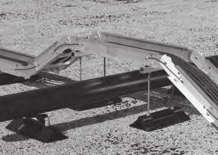
2 Style Cable Tray Typical Installations Chalfant Cable Trays

3 Tray When metal ladder cable trays came of age, they were used to support the new armored shielded power cables that were permitted outside the conduit environment. Utilities and industrial companies initiated the use of expanded metal and solid trough-styled trays for supporting power and control cable. Cable trays quickly proved their worth as a safe, dependable and cost-effective solution to routing and supporting cables. Installed cost savings of over 50% on project after project drove the market for metal cable trays to over 80 million dollars. Cable Tray is NOT WIEWY and is viewed as a support for cables. This provides the designer and user many benefits. Full free air rating of cables, results in smaller conductors vs. conduit Greater fill volume allowed, results in less space Used in all locations except elevator shafts (the only prohibition on cable tray use) Used as an equipment grounding conductor (classified by UL) Less stress on cables during installation and operation Increased safety, no moisture condensation problems nor transmission of corrosive or explosive gases, as with conduit Simplified maintenance with the flexibility of adding or changing circuits Simplified engineering and construction. dd, change, modify more easily Used with other wiring methods Longer support spans up to 55 (Chalfant s standard systems to 40 ).


4 Quick Find Index Cable Tray Straight Sections Pages 5-11 luminum Description: Page 1-5 Selection: Pages 1-6 & 1-7 Steel/Stainless Steel Description: Page 1-5 Selection: Pages 1-8 & 1-9 Fittings Pages orizontal ends Outside Vertical ends Inside Vertical ends Tees Crosses 90 Page Page Page Page Page Page Page Page Page Page Page Page 1-15 Page 1-16 Page 1-16 Support iser Wyes Vertical Tee Up Vertical Tee Down Tee with Outside Tap Page 1-16 Page 1-17 Page 1-17 Page 1-17 Page 1-18 ccessories Pages Fasteners Splice Plates educer Splice Plates Side ail Dropouts Wall Frames Tray to Panel Cross ung 4" Page 1-25 Page 1-19 Page 1-19 ung Drop-Out Page 1-19 Page 1-19 Page 1-19 Covers Clamps lind Ends arriers Expansion Gap Support Equipment Page 1-20 Page 1-20 Page 1-21 Page 1-22 Page 1-23 Page Chalfant Cable Trays
5 Selecting & Sizing Cable Tray Systems The Cable to be Supported Determines the Type of Tray type cable can support heavy power cables or small circuit size communication cables for control data and phone cables or a mix. ung Spacing: Single conductor over 4/0 and MC cables should be used with 12 or 18 rung spacing. Smaller diameter cables require 6 or 9 rung spacing. Trough, solid or ventilated type tray offer protection and better support for small, lightweight instrument or data cables. ints: arrier strips can be used to separate voltages or power and control cables to avoid the cost of adding a second or separate tray for each. Covers are not required by the NEC Code and add to the cost of the job. owever, they should be considered for protection of personnel and any debris or other material that could fall into the tray. 1 3 Select which Metal and/or Material Finish Your 2 pplication Will equire The job site and its environment will determine which metal and/or material finish you use. eview where the tray is being used. re there unusual corrosive conditions (like those found in some chemical and paper processing plants)? See page 1-4 for a list of various tray materials and finishes available. ints: luminum - Most conditions are satisfied by aluminum tray which is also the most popular type. It s less expensive and an easier system to install. Unlike galvanized steel, its finish is always smooth. Longer span tray systems are also available in aluminum. luminum tray is ideal for seacoast, offshore and most petrochemical and pulp mill applications. Galvanized Steel (DGF STM 123 Class 2) - This hot dipped galvanized steel is used in outdoor, chlorine, acid or caustic areas. Steel trays can have a rough finish (VE 1) which could cause cable damage. It also adds two to three weeks to delivery time. Trays with mill galvanize steel finish STM 653 are the least expensive and only recommended for indoor applications. Stainless Steel trays are used in special highly corrosive environments and compare favorably with fiberglass type ladder tray. Determine Type of Support int: eview the various support methods and options shown in the accessories section of this catalog on pages 1-20, 1-21, 1-24, and The distance between each support is the support span. You can support your cable tray system: from walls or vertical columns with shelf or cantilevered brackets with trapeze or single supports using threaded rods hung directly from building steel on or under pipe racks, trestles or bridges In utility trenches, tunnels or directly on roofs off the ground, using pedestal supports. int: You can save money by using a heavier duty tray that results in longer spans and reduces the number of costly supports and installation time. heavier duty tray will also provide a deeper loading depth and a stronger, less deflective, long-span support. Determine Cable Load 4 to be Supported eview the number and type of cable from the job specifications and requirements. Cable fill in a tray is calculated by using data and criteria specified in NEC 392. To determine total cable weight, add all cables on a lb/ft basis. ints: Data, telephone and instrument cable should be calculated to fill tray to 50% of the tray cross section fill area (40% for solid bottom tray). In reality, because of voids, overlapping and the circular shape of the cable, a 50% fill will normally completely fill the cable tray. MC cable 4/0 or larger, rated 2000 Volts or less, can only be installed in one layer (sum of cable diameters equals tray width). Single conductor 2000 Volts or less, larger than 1000 KCM can only be installed in one layer (sum of cable diameters equals tray width). Other power cables and combinations of sizes are calculated on the sum of cable areas versus allowable fill, see table NEC to determine tray width. NEC 392 details cable types, voltages, ampacity, etc. Other Loads to be Calculated: Snow: dd 13.3 lbs/square feet for 20-inch deep wet snow. (Example: For a 36-inch tray width - 3 X 13.3 = 39.9 lbs/sq ft.) Ice: dd 4.7 lbs/square feet. Concentrated Load: dd load effect (W e ) for concentrated load effect from splice boxes, heavy cable drop outs and conduit terminations supported off tray. W e = 2 times the concentrated load divided by the support span. (Example: For a 200 lbs. concentrated load at a center span of 20 ft, W e = 2 X 200/20 = 20 lbs. per ft added load. ) Once you have determined your worst case load, add it to your other cable load calculations. You now have the maximum load the tray must support. ints: It is not necessary to specify tray rung type when using Chalfant. Chalfant rung designs can handle a minimum of 350 lbs. at any width. Chalfant uses 3 rung styles to assure this standard is maintained. For example, Strut ung #11118 is rated at 489 lbs. at 36 wide. eview You have now determined: 1. Tray type 2. Tray material and/or finish 3. Support type & span between supports 4. Total load in lbs/ft 5 Select Tray System (For aluminum, use Selection Chart on pages 1-6,1-7, 1-8 and 1-9.) (For steel, use Selection Chart on pages 1-8 and 1-9.) eview Selection chart and the various notes in general. Start at the top of (your) support span column and work down to locate a tray system to handle your total load. Example: You have determined you need a ladder tray (aluminum) at a 20 ft span and 100 lbs/ft load. Using Selection Chart on pages 1-6 and 1-7, go down 20 ft span column until you reach Tray System 46. This is the best tray for your application. Note: If you use a shorter span, you must choose between a 3,4 or 5 load depth. Order your tray using the Part No. Code on page 1-4. Contact your Chalfant Sales epresentative or the factory if you need help sizing and selecting your tray. Chalfant Cable Trays 1-3


6 Ordering Codes and Options Part Number/Ordering Codes Once you have determined the appropriate Chalfant tray system to meet your loading depth and load/span requirements, use the following numbering systems to order straight sections, fittings and accessories. Cable Tray Straight Sections (luminum or Steel) Example: 2 luminum System 12 long, 6 wide, with 9 rung spacing * Tray System Number Cable Tray Fittings (luminum or Steel) Example: 90 luminum orizontal end 12 radius Tray System Number Type of Material See chart at right *T=Trough Style S=Solid ottom X=Expanded Metal Trough M=Marine ung ccessories Tray Width 6, 9, 12,18, 24, & 42" Type of Material Tray Width 6, 9, 12,18, 24, & Chalfant Cable Trays ung Spacing 6, 9, 12 & 18 or T, S, & X* Constant for 12 & 24 straight sections Insert inches for special lengths: 120=10 Meters 240=20 118=3 360=30 236=6 Length lank=12 L=24 Three Digit Part Number from Catalog Example: 4-olt Slotted ole Splice Plate Tray System Number or 9 2 SP200 Type of Material Part Number from Catalog Options Chalfant style cable tray is available in a variety of options to satisfy your needs. Materials/Finishes Following is a list of various materials of construction and/or finishes that can be applied to straight sections, fittings and some accessories. Use these codes when ordering. * Material Code: = luminum, igh Strength 6063T6 Extrusions ( sheet) S = ot Dip Mill Galvanized Steel to STM 653 G-90 Coating, 1.05 Mils Thick G =ot Dip Galvanized after Fabrication to STM 123-2, 2.55 Mils Thick T = 304L Stainless Steel Z = 316L Stainless Steel Other Options ll Tray systems are easily modified to offer: Ventilated Trough 2.5 wide rungs MIG welded on 6 centers. lso available with 9 and 12 rung spacing. To order, add letter T, 09T, or 12T instead of rung spacing in straight section part number. Solid Trough solid sheet is supported by a 12 rung spaced tray. To order, add letter S instead of rung spacing in straight section part number. For Fittings, add suffix S to the part number. Expanded Metal Trough.5 diamond pattern aluminum sheet is supported by a 12 rung spaced tray. To order, add letter X instead of rung spacing in straight section part number. For Fittings, add suffix X to the part number. See Page Marine Strut ung special rung design to accommodate stainless steel banding of cables. (USCG requirement) ung supports 460 lbs. per rung on a 36 wide system with a 1.5 safety factor. dd suffix M (rung spacing) to the part number. Consult Factory for full technical data on individual systems, corrosion resistance charts, etc.
 are classified by UL as an equipment ground conductor.")


7 Straight Sections Most Chalfant cable tray system side rails are stocked in 12 and 24 lengths. You can special order 30 lengths for 875 and 8F trays or 40 lengths for 103 tray. ll trays meet or exceed NEM VE-1 standards and NEC rticle 392. ll trays (except stainless) are classified by UL as an equipment ground conductor. See Selection Guides for allowable grounding amps for each tray system. Lengths: Standard 12 and 24 Widths: Standard 6, 9,12, 18, 24, 30, 36 & 42 ung Spacing: Standard 6, 9,12 and 18 ail Loading eight Depth Tray Systems , 24, 2, 34, 248, , 35, 45, or 6 16, 26, 2, 3, 46, 665, 268, 366, , , 8F (Fittings have 8 siderail) Splice Plates Splice plates are 1 8 thick with 4-bolt slotted holes. This flat plate design permits fast, easy fit-up in the field. 665, 47 & 57 systems have 8 bolt/plates. 8 and 10 trays have 10 bolt/plates which are 16 long, 3 16 thick. Special time saving stainless steel fasteners are standard. luminum Cable Tray luminum cable tray is the most popular tray in use today. Chalfant has a wide offering in aluminum tray from light duty commercial/institutional systems for data and telephone support to utility/ industrial grade tray and extra heavy duty long span tray to 30 spans. Ideal for most corrosive atmospheres including offshore, seacoast and petro-chemical applications. Not recommended for use in chlorine, caustic or high acid environments. ungs ungs are box construction 0.9 high with 7 8, 1 and bearing surface. ll trays (except 14) and rungs are designed to handle cable loads plus 200 lbs. of concentrated load for any tray width. For example, strut rung #11118 can handle 489 lbs. at a 36. Low profile rungs are available in to provide a 6 load depth. Galvanized and Stainless Steel Tray ot Dip Mill galvanized tray STM 653 G90 coating is the least expensive tray and is recommended for indoor applications only. ot dipped galvanized after fabrication STM 123 is recommended for outdoor use. It is more expensive than aluminum and requires great care in galvanizing to prevent icicles, bare patches, warpage and rough surfaces. Stainless steel tray is available in 304L and 316L and is often the least expensive solution for use in highly corrosive atmospheres. It also competes favorably against fiberglass systems. Steel ungs ungs are 1 high with 3 4 bearing, 18 gauge. special gas relief hole for DGF is punched on both ends to assure complete galvanizing. Chalfant Cable Trays 1-5
8 Cable Tray Selection Guide NEM Support Span (Simple eam Data) eight Load/Span luminum Side Load ating (@1.5 Safety System No. ail Depth (1.83) m (2.44) m (3.05) m (3.66) m Factor) (102) (81) 8C (102) (76) (102) (76) 12C (102) (76) (127) (107) (127) (102) 12C (127) (102) C (160) or (140/152) (160) or C (137/152) (160) or (137/152) (160) or C (137/152) C 288 (160) or (137/152) It is not economical to use long.0038 span tray systems for short C 7 span installation. Move up to 430 (165) or 6 4 a lighter duty system (137/152) C 288 (187) (163) C 425 (188) (163) Key: 1 = Cable Loading (lb/ft) 2 = Mid Span Deflection (in) 3 = K Factor (in/lb/ft) Nominal Loading Depth per VE-1 with reinforced low profile rung Exceeds NEM Loads by over 20% Weight shown (lbs/ft or Kg/M) for 24 width tray with 9 rung spacing NEM Load/Span Factor of Safety From VE-1 Table 1 Working Load Support Span (lbs/linear ft.) 8 Ft 12 Ft 16 Ft 20 Ft =50 lbs/ft =75 lbs/ft C=100 lbs/ft 8C 12C 16C 20C Chalfant Cable Trays 7 8
9 Support Span (Simple eam Data) Data (2-ails) NEC Tray Ix Sx rea 392-7(b)2 Weight (4.27) m (4.88) m (5.49) m (6.10) m (7.32) m (9.14) m In 4 In 3 In 2 EGC MPS Lbs Per Ft (555) (2.66) (645) (2.90) (735) (3.20) (923) (3.66) (658) (2.98) (768) (3.27) (942) (3.75) (774) (3.30) (826) (3.47) (1000) (3.93) (1187) (4.43) (1361) (4.94) (1852) (6.29) (1366) (4.96) (1690) (5.68) Conversion to Metric Meters = X feet Kg/m = X lb/ft mm = 25.4 X inches Convert Load Data To convert into a safety factor = 2.0 multiply loading values by 0.75 (ratio of 1.5/2.0) K x W = Deflection for other loads (inches) 7 NEM does not list 24, 30 & 40 span trays. Chalfant Cable Trays 1-7
10 Cable Tray Selection Guide Support Span (Simple eam Data) NEM eight Load/Span luminum Side Load ating System No. ail Depth Safety (4.27) m (4.88) m Factor) C (203) (178) 24C C F (203) (178) C (254) (225) 6 Steel NEM Support Span eight Load/Span Side Load ating 6 8 (@1.5 Safety System No. Gauge ail Depth Factor) (1.83) m (2.44) m Steel/Stainless 248* 346* 258* 268* 366* (1.3) (102) (76) (1.6) (102) (76) 12C (1.3) (127) (102) (1.3) (160) (132) 12C (1.6) (160) (132) 16C 4 364* C (1.9) (160) (132) 16C 5 4 Stainless Steel 248* 268* 366* 364* (1.2) (102) (76) C 272 (1.2) (160) (137) 12C (1.5) (160) (137) 16C C (1.9) (160) (137) 16C S = ot Dip Mill Galvanized to STM 653 G = ot Dip Galvanized after Fabrication to STM * Material Code: G-90 coating 1.06 Mils Thick 2.55 Mils Thick (eplaced STM 386) Key: 4 Exceeds NEM Loads by over 20% NEM Working Load Support Span Load/Span 1 = Cable Loading (lb/ft) 5 Weight shown (lbs/ft or Kg/M) for (lbs/linear ft.) 8 Ft 12 Ft 16 Ft 20 Ft Designations 2 = Mid Span Deflection (in) 24 width tray with 9 rung Factor =50 lbs/ft = K Factor (in/lb/ft) 6 NEM does not list 24, 30, 35 & 40 spans of Safety =75 lbs/ft C=100 lbs/ft 8C 12C 16C 20C From VE-1 Table Chalfant Cable Trays
11 Support Span (Simple eam Data) Data (2-ails) NEC Tray Ix Sx rea 392-7(b)2 Weight (5.49) m (6.10) m (7.32) m (9.14) m (10.7) m (12.2) m In 4 In 3 In 2 EGC MPS Lbs Per Ft (2735) (9.69) (3432) (11.19) (4555) (14.06) Support Span (Simple eam Data) Data (2-ails) NEC Tray Ix Sx 392-7(b)2 Weight (3.05) m (3.66) m (4.27) m (4.88) m (5.49) m (6.10) m In 4 In 3 EGC MPS Lbs Per Ft * (5.43) (6.18) (5.65) (6.35) (7.50) (8.82) ** (5.43) ** (6.35) ** (7.50) ** (8.82) Material Code: T= 304L Stainless Steel Z= 316L Stainless Steel Conversion to Metric Meters = X feet Kg/M = X lb/ft mm = 25.4 X inches Convert Load Data To convert into a safety factor = 2.0. multiply loading values by (ratio of 1.5/2.0) K x W = Deflection for other loads (inches) ** For EGC run separate ground wire. Chalfant Cable Trays 1-9
12 90 orizontal end Fittings 90 & 60 orizontal Fittings ll Tray Fittings have rungs on 9 centers with 3" tangents for easy fit-up during installation. Each fitting and straight section comes with a pair (2) splice plates and eight (8) 9TN302 nut and bolt assemblies, with the exception of 8 & 10 trays that have 8 tangents and 10 bolt splice plates. 8 trays available in 36 & 48 radius. 7 trays in 24 radius. Consult factory for fitting dimensions. 60 orizontal end Number of rungs vary depending on radius. Dimensions Part W Number (457) 18 (457) * (305) (495) 19.5 (495) * (533) 21 (533) * (610) 24 (610) * (686) 27 (686) * (762) 30 (762) * (838) 33 (838) * (914) 36 (914) * (991) 39 (991) * (762) 30 (762) * (610) (800) 31.5 (800) * (838) 33 (838) * (914) 36 (914) * (991) 39 (991) * (1067) 42 (1067) * (1143) 45 (1143) * (1219) 48 (1219) * (1295) 51 (1295) * (1067) 42 (1067) * (914) (1105) 43.5 (1105) * (1143) 45 (1143) * (1219) 48 (1219) * (1295) 51 (1295) * (1372) 54 (1372) * (1448) 57 (1448) * (1524) 60 (1524) * (1600) 63 (1600) * (1372) 54 (1372) * (1219) (1410) 55.5 (1410) * (1448) 57 (1448) * (1524) 60 (1524) * (1600) 63 (1600) * (1676) 66 (1676) * (1753) 69 (1753) * (1829) 72 (1829) * (1905) 75 (1905) * Dimensions Part W Number (424) 13.1 (333) * (305) (457) 15.4 (390) * (488) 17.6 (447) * (549) 22.1 (561) * (612) 26.6 (676) * (673) 31.1 (790) * (737) 35.6 (904) * (798) 40.1 (1019) * (861) 44.6 (1133) * (673) 19.1 (485) * (610) (706) 21.4 (544) * (737) 23.6 (599) * (798) 28.1 (714) * (861) 32.6 (828) * (922) 38.1 (968) * (985) 41.6 (1057) * (1046) 46.1 (1171) * (1110) 50.6 (1285) * (922) 25.1 (638) * (914) (955) 27.4 (695) * (986) 29.6 (752) * (1147) 34.1 (866) * (1110) 38.6 (980) * (1171) 43.1 (1095) * (1234) 47.6 (1209) * (1295) 52.1 (1323) * (1359) 56.6 (1438) * (1171) 31.1 (790) * (1219) (1201) 33.4 (847) * (1234) 35.6 (904) * (1295) 40.1 (1019) * (1359) 44.6 (1133) * (1420) 49.1 (1247) * (1483) 53.6 (1361) * (1544) 58.1 (1476) * (1608) 62.6 (1590) * W=Widths in Inches (mm) 6 (152) 30 (762) 9 (229) 36 (914) 12 (305) 42 (1067) 18 (457) 48 (1176) 24 (610) =Side ail eight in Inches (mm) 4 (101) 7.3 (179) Consult Factory 5 (127) 8 (203) Consult Factory 6.3 (160) Tray System * Type of Material See Page 1-4 for Selection. For Steel Fitting Part Numbers Use: 4 igh Tray = 246 * 5 igh Tray = 256 * 6 igh Tray = 266 * For Covers and arriers See ccessories Section, Pages Chalfant Cable Trays
13 45 & 30 orizontal Fittings ll Tray Fittings have rungs on 9 centers with 3" tangents for easy fit-up during installation. Each fitting and straight section comes with a pair (2) splice plates and eight (8) 9TN302 nut and bolt assemblies. 45 orizontal end 30 orizontal end Number of rungs vary depending on radius. Dimensions Part W Number (400) 9.51 (242) * (305) (426) (291) * (455) (340) * (507) (439) * (561) (537) * (615) (636) * (669) (734) * (723) (833) * (777) 36.6 (9300) * (615) 13.0 (331) * (610) (642) 14.9 (380) * (669) 16.9 (430) * (723) 20.8 (528) * (777) 24.7 (626) * (831) 28.5 (725) * (884) 32.4 (823) * (938) 36.3 (922) * (993) 40.2 (1021) * (831) 16.5 (420) * (914) (857) 18.5 (469) * (884) 20.4 (519) * (938) 24.3 (617) * (992) 28.2 (716) * (1046) 32.1 (814) * (1100) 35.9 (913) * (1154) 39.8(1011) * (1208) 43.7(1110) * (1046) 20.1 (510) * (1219) (1073) 22.0 (559) * (1100) 23.9 (608) * (1154) 27.8 (706) * (1208) 31.7 (805) * (1262) 35.6 (903) * (1315) 39.5 (1002) * (1369) 43.3 (1100) * (1422) 47.2 (1199) * Dimensions Part W Number (333) 6.51 (165) * (305) (353) 8.21 (209) * (371) 9.91 (252) * (422) (338) * (447) (425) * (485) (511) * (523) (597) * (561) (674) * (601) (770) * (485) 8.12 (206) * (610) (505) 8.95 (227) * (523) (293) * (561) (379) * (599) (465) * (638) (553) * (663) (638) * (714) (725) * (739) (811) * (638) 9.73 (247) * (914) (658) (290) * (676) (334) * (714) (420) * (752) (506) * (790) (593) * (828) (679) * (866) (766) * (904) (852) * (790) (288) * (1219) (810) (331) * (828) (374) * (866) (461) * (904) (547) * (942) (633) * (980) (720) * (1019) (806) * ( (893) * Tray System * Type of Material See Page 1-4 for Selection. For Steel Fitting Part Numbers Use: 4 igh Tray = 246 * 5 igh Tray = 256 * 6 igh Tray = 266 * For Covers and arriers See ccessories Section, Pages Chalfant Cable Trays 1-11
14 90 Outside end 90 Outside & Inside Vertical end Fittings ll Tray Fittings have rungs on 9 centers with 3" tangents for easy fit-up during installation. Each fitting and straight section comes with a pair (2) splice plates and eight (8) 9TN302 nut and bolt assemblies. 90 Inside end Number of rungs vary depending on radius. Outside Vertical end Inside Vertical end @6.3 Part W Number Number 12 6 * * (305) 9 * * * * (381) 15 (381) * (483) 19 (483) 20 (508) 20 (508) 22.3 (566) 22.3 (566) * * * * * * * * * * * * * (610) 9 * * * * (686) 27 (686) * (787) 31 (787) 32 (813) 32 (813) 34.3 (871) 34.3 (871) * * * * * * * * * * * * * (914) 9 * * * * (991) 39 (991) * (1092) 43 (1092) 44 (1118) 44 (1118) 46.3 (1176) 46.3 (1176) * * * * * * * * * * * * * (1219) 9 * * * * (1295) 51 (1295) * (1397) 55 (1397) 56 (1422) 56 (1422) 58.3 (1481) 58.3 (1481) * * * * * * * * * * * W=Widths in Inches (mm) 6 (152) 30 (762) 9 (229) 36 (914) 12 (305) 42 (1067) 18 (457) 48 (1176) 24 (610) =Side ail eight in Inches (mm) 4 (101) 7.3 (179) Consult Factory 5 (127) 8 (203) Consult Factory 6.3 (160) Tray System * Type of Material See Page 1-4 for Selection. For Steel Fitting Part Numbers Use: 4 igh Tray = 246 * 5 igh Tray = 256 * 6 igh Tray = 266 * For Covers and arriers See ccessories Section, Pages Chalfant Cable Trays
15 60 Outside & Inside Vertical end Fittings ll Tray Fittings have rungs on 9 centers with 3" tangents for easy fit-up during installation. Each fitting and straight section comes with a pair (2) splice plates and eight (8) 9TN302 nut and bolt assemblies. 60 Outside end 60 Inside end Number of rungs vary depending on radius. Outside Vertical end Inside Vertical end @6.3 Part W Number Number 12 6 * * (305) 9 * * * * (218) 14.9 (378) * (269) (466) 11.1 (282) (488) 12.7 (323) 21.1 (536) * * * * * * * * * * * * * (610) 9 * * * * (371) 25.3 (642) * (422) (730) 17.1 (434) (752) 18.7 (475) 31.5 (800) * * * * * * * * * * * * * (914) 9 * * * * (523) (907) * (579) (994) 23.1 (587) (1016) 24.7 (627) 41.9 (1064) * * * * * * * * * * * * * (1219) 9 * * * * (676) 46.1 (1170) * (726) (1258) 29.1 (739) 50.4 (1280) 30.7 (780) 52.2 (1328) * * * * * * * * * * * Tray System * Type of Material See Page 1-4 for Selection. For Steel Fitting Part Numbers Use: 4 igh Tray = 246 * 5 igh Tray = 256 * 6 igh Tray = 266 * For Covers and arriers See ccessories Section, Pages Chalfant Cable Trays 1-13
16 45 Outside end 45 Outside & Inside Vertical end Fittings ll Tray Fittings have rungs on 9 centers with 3" tangents for easy fit-up during installation. Each fitting and straight section comes with a pair (2) splice plates and eight (8) 9TN302 nut and bolt assemblies. 45 Inside end Number of rungs vary depending on radius. Outside Vertical end Inside Vertical end @6.3 Part W Number Number 12 6 * * (305) 9 * * * * (143) 13.6 (356) * (173) 16.4 (417) 7.1 (180) 17.1 (435) 7.8 (198) 18.8 (478) * * * * * * * * * * * * * (610) 9 * * * * (232) 22.1 (561) * (262) (633) 10.6 (270) 25.6 (651) 11.3 (287) 27.3 (693) * * * * * * * * * * * * * (914) 9 * * * * (322) 30.6 (777) * (351) 33.4 (849) 14.1 (359) (867) 14.8 (376) 35.7 (907) * * * * * * * * * * * * * (1219) 9 * * * * (411) 39.1 (922) * (441) 41.9 (1064) 17.6 (448) 42.6 (1082) (465) 44.2 (1123) * * * * * * * * * * * W=Widths in Inches (mm) 6 (152) 30 (762) 9 (229) 36 (914) 12 (305) 42 (1067) 18 (457) 48 (1176) 24 (610) =Side ail eight in Inches (mm) 4 (101) 7.3 (179) Consult Factory 5 (127) 8 (203) Consult Factory 6.3 (160) Tray System * Type of Material See Page 1-4 for Selection. For Steel Fitting Part Numbers Use: 4 igh Tray = 246 * 5 igh Tray = 256 * 6 igh Tray = 266 * For Covers and arriers See ccessories Section, Pages Chalfant Cable Trays
17 30 Outside end 30 Outside & Inside Vertical end Fittings ll Tray Fittings have rungs on 9 centers with 3" tangents for easy fit-up during installation. Each fitting and straight section comes with a pair (2) splice plates and eight (8) 9TN302 nut and bolt assemblies. 30 Inside end Number of rungs vary depending on radius. Outside Vertical end Inside Vertical end @6.3 Part W Number Number 12 6 * * (305) 9 * * * * (79) 11.6 (295) * (93) 13.6 (345) 3.8 (96) 14.1 (358) 3.9 (100) 14.8 (375) * * * * * * * * * * * * * (610) 9 * * * * (120) 17.6 (447) * (133) 19.6 (498) 5.4 (137) 20.1 (511) 5.6 (141) 20.8 (527) * * * * * * * * * * * * * (914) 9 * * * * (161) (599) * (174) 25.6 (650) 7.0 (178) 26.1 (663) 7.2 (182) 27.1 (688) * * * * * * * * * * * * * (1219) 9 * * * * (201) (752) * (215) 31.6 (803) 8.6 (218) 32.1 (815) 8.8 (223) 32.8 (832) * * * * * * * * * * * Tray System * Type of Material See Page 1-4 for Selection. For Steel Fitting Part Numbers Use: 4 igh Tray = 246 * 5 igh Tray = 256 * 6 igh Tray = 266 * For Covers and arriers See ccessories Section, Pages Chalfant Cable Trays 1-15
18 Fittings ll Tray Fittings have rungs on 9 centers with 3" tangents for easy fit-up during installation. Tee W Cross W 90 Vertical Support iser Each Tee fitting comes with two pairs (4) of splice plates and sixteen (16) 9TN302 nut and bolt assemblies. Each Cross fitting comes with three pairs (6) of splice plates and twenty four (24) 9TN302 nut and bolt assemblies. Each iser comes with a pair of (2) splice plates and eight (8) 9TN302 nut and bolt assemblies. Dimensions Part W Number (457) 36 (914) * (305) (495) 39 (991) * (533) 42 (1067) * (610) 48 (1549) * (686) 54 (1372) * (762) 60 (1524) * (838) 66 (1676) * (914) 72 (1829) * (991) 78 (1981) * (762) 60 (1524) * (610) (800) 63 (1600) * (838) 66 (1676) * (914) 72 (1829) * (991) 78 (1981) * (1067) 84 (2134) * (1143) 90 (2286) * (1219) 96 (2438) * (1295) 102 (2591) * (1067) 84 (2134) * (914) (1105) 87 (2210) * (1143) 90 (2286) * (1219) 96 (2438) * (1295) 102 (2591) * (1372) 108 (2743) * (1448) 114 (2896) * (1524) 120 (3048) * (1600) 126 (3200) * (1372) 108 (2743) * (1219) (1410) 111 (2819) * (1448) 114 (2896) * (1524) 120 (3048) * (1600) 126 (3200) * (1676) 132 (3353) * (1753) 138 (3505) * (1829) 144 (3658) * (1905) 150 (3810) * Dimensions Part W Number (457) 36 (914) * (305) (495) 39 (991) * (533) 42 (1067) * (610) 48 (1549) * (686) 54 (1372) * (762) 60 (1524) * (838) 66 (1676) * (914) 72 (1829) * (991) 78 (1981) * (762) 60 (1524) * (605) (800) 63 (1600) * (838) 66 (1676) * (914) 72 (1829) * (991) 78 (1981) * (1067) 84 (2134) * (1143) 90 (2286) * (1219) 96 (2438) * (1296) 102 (2591) * (1067) 84 (2134) * (762) (1105) 87 (2210) * (1143) 90 (2286) * (1219) 96 (2438) * (1295) 102 (2591) * (1372) 108 (2743) * (1448) 114 (2896) * (1524) 120 (3048) * (1600) 126 (3200) * (1372) 108 (2743) * (1219) (1410) 111 (2819) * (1448) 114 (2896) * (1524) 120 (3048) * (1600) 126 (3200) * (1676) 132 (3353) * (1753) 138 (3505) * (1829) 144 (3658) * (1600) 150 (3810) * Dimensions Part W Number 12 6 * (305) 9 * * (381) 15 (381) * * * * * * * (610) 9 * * (686) 27 (686) * * * * * * * (914) 9 * * (991) 39 (991) * * * * * * * (1219) 9 * * (1295) 51 (1295) * * * * * * Expansion & educer Tees can be custom fabricated at standard Tee pricing. Specify various widths counter clockwise (using drawing above) starting at left. Tray System * Type of Material See Page 1-4 for Selection Chalfant Cable Trays Expansion & educer Crosses can be custom fabricated. Specify various widths counter clockwise (using drawing above) starting at left. For Steel Fitting Part Numbers Use: 4 igh Tray = 246 * 5 igh Tray = 256 * 6 igh Tray = 266 * For Covers and arriers See ccessories Section, Pages
19 Fittings ll Tray Fittings have rungs on 9 centers with 3" tangents for easy fit-up during installation. Left or ight and Wye Vertical Tee 1 C 1 Vertical Tee Up W Number of rungs vary depending on tray width. Vertical Tee Down Part W 1 C 1 Number (216) (400) (305) (108) (368.0) (323) (561) (457) (162) (551.9) (431) (723) (610) (215) (735.8) (647) (1046) (914) (323.3) (1103.9) (862) (1369) (1219) (431.0) (1471.7) (1078) (1693) (1524) (538.7) (1839.7) (1293) (2016) (1829) (646.7) (2194.8) (1509) (2339) (2134) (741.7) (2575.6) (1725) (2650) (2438) (862.1) (2943.9) * W 172 IGT and or * W 173 LEFT and Dimensions/Side ail eight= Part Number * W 095 (305) (381) (864) (381) (889) (381) (922) * W 095U (483) (864) (508) (889) (566) (922) * W 097 (610) (686) (1473) (686) (1499) (686) (1532) * W 097U (787) (1473) (813) (1499) (871) (1532) * W 098 (914) (991) (2083) (991) (2108) (846) (2141) * W 098U (1092) (2083) (1118) (2108) (1176) (2141) Special Wyes can be made with two different tray widths. Consult factory. Each Wye is furnished with two pairs (4) of splice plates and eight (8) 9TN302 nut and bolt assemblies * W 099 (1295) (2692) (1295) (2718) (1295) (2751) * W 099U (1397) (2692) (1422) (2718) (1481) (2751) Each Vertical Tee is furnished with two (2) pairs of splice plates and sixteen (16) 9TN302 nut and bolt assemblies. Fitting educers Fitting educers are available in right hand, left hand or concentric styles as a special order. Consult Factory. Chalfant strongly recommends the use of offset splice plate reducers which are 1 3 the cost and 1 2 the labor to install while doing the same job. See Page 1-19 in the ccessories Section. Fitting Covers Covers vailable in Flanged and Flat styles only. See page 1-20 in the ccessories Section. To order covers substitute the Tray System number ( ) with a 7 for the Flanged style cover or a 67 for a Flat cover style. Example: Tray part Number Flanged Flat arriers vailable for orizontal and Vertical fittings. See page 1-22 in the ccessories Section. To order Vertical arriers substitute the Tray System number ( ) with an 8. and substitute S, as shown. Example: Tray part Number [arrier eight] 8 S For orizontal arriers See Page 1-22 and specify part number 8 * S340-. Tray System * Type of Material See Page 1-4 for Selection. Chalfant Cable Trays 1-17
 S = ot Dip Mill Galvanized Steel to STM 653 G-90")
20 Cable Tray ccessories Chalfant s complete line of accessories are designed to be used with the following Cable Tray Systems: ow to Order Example: 4-olt Slotted ole Splice Plate 2 SP200 Tray System Number Type of Material See material codes * Part Number from Catalog * Material Code: =luminum, igh Strength 6063T6 Extrusions ( sheet) S = ot Dip Mill Galvanized Steel to STM 653 G-90 Coating, 1.05 Mils Thick G =ot Dip Galvanized after Fabrication to STM Mils Thick (replaced STM 386) T = 304L Stainless Steel Z = 316L Stainless Steel Cable Tray ccessories Integral inged Cover M24 M29 Tee with Drop-Out 24 W VOT-W 2 (vertical outside tap) 24 W VIT-W 2 (vertical inside tap) alf-turn Spring Latch vailable in 24 and 29 systems in twelve foot standard lengths. Material is 6063 luminum lloy. 3" W2 3" W1 Tee with Inside Tap (Up) 3" Channel ail Tee with Outside Tap (Down) 3" Channel ail eavy-duty Vertical old Down racket 9SD590 W2 + 19" W 1 = Width of orizontal un W 2 = Width of Vertical Tap vailable in any tray size in systems 2 through 665. Material is 6063 luminum lloy. See page 1-6 for selection Chalfant Cable Trays
21 4 olt Splice Plate Cable Tray Splice Plates and dapters Note: ll splice plates are shipped in pairs with necessary stainless steel hardware. 8 ole Long Splice Plate dapter Splice Plate * SP200 * SP209 9 * SP286 8 to 6 9 * SP265 6 to 5 9 * SP264 6 to 4 9 * SP254 5 to 4 orizontal djustable Splice Plate * SP210 0 to 30 7" 24" Note: nti-oxide compound is not needed behind plates Per NEM VE-2. Special Order Field drill holes this side after angle is set. Vertical djustable Splice Plate Mid-Span Splice Plate educer Splice Plates * SP212 L W Splice Plate Left and or ight and 0 to 45 Field drill hole next to pivot point after angle is set. luminum splice plates are shipped in pairs with stainless steel hardware. ail Tray Part eight Series Number WSP WSP WSP200 Nominal Dimensions Part Numbers W Offset Straight 3 * * varies 6 * * with 9 * * loading 12 * * depth of 18 * * specified 21 * * straight 24 * * sections. 27 * * * * Straight Where application calls for a left or right hand reduction, Chalfant reducing splice plates are sold with a standard splice plate * SP200. For a concentric straight reduction, the dimension W is the total reduction. ung Drop-Out 9 * W198 Tray Width Wall Frame 1 Tier 1-1/2 Tray to Panel Frame 9SW244 W+ 4-3/8 W-2" Tray Width +W Width of Tray to fit O.D. + 4" Side ail 90 lternate Tray to ox Connector * SP213 Cross ung 4" ail Part ung eight W Number Drop-Out * W495 Tray System * Type of Material See Page 1-18 for Selection * W * W Chalfant Cable Trays 1-19
22 Covers and ccessories 20 5 Standard Cover Flat Cover Louvered Cover Peak Cover 20 ain Peaked Cover 7 * W * W * W 010-V 7 * W 010-P 7 * W 010-P Note: Standard cover length is 12. lso available with installed spring latches See elow and Page W=Width Spring Latch Option for Covers Joint 9W196 W For Covers, Expanded Metal and Solid ottoms luminum Expanded Metal ottom 1 2 Diamond Pattern Joint Plate XW " 1".200" Tray Width 12'-0" eavy Duty Cover Strap 7 * W69 1-1/2 Tray Width + 1/8 Peaked Cover eavy Duty Strap 7 * W69-P 7 * W69-P P=5 Slope P=20 Slope Cover Joint Strap 7 * W196 4" Peaked Cover lind End 7 * W Width 11/16 Tray Width + 2" +1/32 1" W Installs with Self-Tapping Screws (Pg. 1-25) or Cover Clamp 7 * CC262 W 1" aised Cover aised Cover Clamp Channel Clamp I-eam 7 * CC70C 7 * CC70E E=1, 2, 3 Elevated luminum Cover Clamp or Conduit racket 7CC262 Cover Clamp E E For galvanized steel order 7SCC262 anger od Clamp 9SC239 ll Channel Tray 9/16 DI. 1-5/8 1-1/2 anger od Clamp 9SC257 3, 26 & 46 Tray 9SC249 2,34 & 35 Tray 1-1/2 3" 3-17/32 I.D Chalfant Cable Trays 1-1/4 I.D. Note: See page 1-24 for hanger rods. Note: See page 1-24 for hanger rods. 3-1/8 I.D. 9/16 DI.
23 Wall racket Clamp Channel 9S0248 3/4 I.D. 7/8 O.D. old Down Clamp 9 * C250 1/2 DI. old Down Web old Down 9/16 DI. 1" Support For I-eam 9S /2 1-1/2 =4 (2 Systems) 5 (35 Systems) 6 (3 Systems) Drill holes 1.25" on either side of Web for mounting on steel. Used on either side with aluminum I-beam. Installs on inside of C-Channel. aised Support Splice Plate * SP200- lind End * W245 6" W W * SP213 Load Depth ung Can be installed flange in or out 1" Floor 90 Used on C-Channel side rails, only. U.S. Patent 4,596,095 Stainless Steel ung Cable Clamp ung 1-1/8 5/16 1/2 3/8 O. D. of Cable Part Numbers TLC TLC TLC TLC TLC TLC TLC TLC TLC TLC TLC TLC TLC TLC TLC adjustment on all clamps. 20 ga. stainless steel with 1/4-20-3/4 bolt and locknut. Optional Conduit Clamp racket 9SC /8 3" 2" Conduit Clamp racket Conduit Clamp (Not Included w/9sc422) Universal Clamp & Conduit Clip 9SC423 (1/2 to 3/4 Conduit) eam Clamps 9SC424 (1/2 to 3/4 Conduit)** otating Clip otating Clip Caddy Design for I-eam Tray System * Type of Material See Page 1-18 for Selection. Caddy Design for C-Channel **Call factory for other conduit sizes. Chalfant Cable Trays 1-21
24 arrier Strip Straight 8 * S010- (For 3 meter length order: 8 * S118-) arriers and Separators orizontal djustable arrier and Formed 8 * S340-12' 48" ll barriers are supplied with (4) 9STK774 magnetic steel self tapping screws. = 3 for 3 and 4 Load Depths 5 for 5 and 6 Load Depths 90 Inside Vertical arrier 12-8 * S * S * S * S07-90 Outside Vertical arrier 12-8 * S * S * S * S05-0=12 adius 2=24 adius 3=36 adius 4=48 adius 0=12 adius 2=24 adius 3=36 adius 4=48 adius For 30, 45 and 60 Vertical arriers, See Page 1-17 arrier lignment Joint Strip (Nylon) 8N06196 Cross Over Separator 8SW 6" 18" W =2 or 4 S=16 Gauge Steel-STM-653 W=6 or 12 Secure to tray with supplied (4), 9STK774 stainless steel self drilling/tapping screws Tray System * Type of Material See Page 1-18 for Selection. arriers Cross Over Separator 1-22 Chalfant Cable Trays
25 Tray Expansion Gap Setting Expansion Joint Components/Gap Setting onding Jumper Gap Maximum Spacing etween Expansion Joints that Provide for One Inch (25.4) Movement Temperature Differential Steel luminum F C Ft. m Ft. m 25 (-4) 512 (156) 260 (79.2) 50 (10) 256 (78) 130 (39.6) 75 (24) 171 (52.1) 87 (26.5) 100 (38) 128 (39.0) 65 (19.8) 125 (51) 102 (31.1) 52 (15.8) 150 (65) 85 (25.9) 43 (13.1) 175 (79) 73 (22.2) 37 (11.3) Expansion Splice Plate Expansion Movement Glide Strip (Optional) Expansion Guide Clamp Metal Temperature at Time of Installation (F or C ) C F F Max. Temp * 0.25 (6.4).50 (12.7).75 (19.1) Gap Settings in.(mm) * Input temperature Max/Min for your location. Min. Temp. * (25.4) Expansion Splice Plate * SP201 Furnished in pairs (2) with (4) 9TN302 nut & bolt assemblies and (4) 9SE519 shoulder bolts, washers and nyloc hex nuts. Expansion Movement Glide Strip Isolation Pad 9NPG259 6" 1-1/2 Expansion Guide Clamp 9 * EX253 9/16 Dia. 2-1/8 onding Jumper 3/8 Dia. Crimped Lug Connector (Tinned) TW Copper Cable (Jacketed) 1-1/2 Tray System * Type of Material See Page 1-18 for Selection. Cable Size ated mps Part Number # CJ200 # CJ600 2/ CJ1000 4/ CJ1600 Furnished with (2) 3 8 fasteners. Field drill mounting holes. llow for 1 expansion. Chalfant Cable Trays 1-23
26 Single Center Support for Tray 9SW263 1/2 X 6 Tubing I-eam Cable Tray 3/8-16 CS w/twist Nut Support Equipment old Down Clamp anger ods L L Part Number 3/8"-16 1/2"-13 12" 9S S " 9S S " 9S S " 9S S " 9S S " 9S S /2 Washer 1/2 Threaded od w/ 1/2 Nut W 1-5/8 X 13/16 Channel w/center Slotted ole Note: ll items are supplied except for 1 2 threaded rod. Trapeze Support racket 9/16 X 1-1/8 Slotted oles on 2" Centerline L 1-5/8 Tray Usable Part* Width L Load (lbs.) Number S S S S S S S42323 Note: anger rods and hardware not included. Standard Channel Strut Part* Number Length Single 9S Double 9S Single 9S20570 Double 9S20572 Shelf Style Wall racket 1-5/8 L Tray Uniform Part* Width L Load (lbs.) Number 6 & S S S S28322 Important: llowance must be made for expansion if temperature extremes exist. Medium Duty Strut Channel racket 2" 1/4 4-5/8 (2) ø 9/16 Thru 1/4 Thick ack Plate Welded to Channel 1-24 Chalfant Cable Trays L 1-5/8 1-5/8 Tray Uniform Part* Width L Load (lbs.) Ga Number 6 & S S S S30580 F.O.S. = 2.5 Securely mounted to wall with proper hardware. * For hot dipped STM 123 galvanized steel after fabrication: specify G for material designation.
Cable Tray Straight Sections Pages Fittings Pages Inside Vertical Bends. 90 Page Page Page Page 1-15
 Premier Ladder Tray When metal ladder cable trays came of age, they were used to support the new armored shielded power cables that were permitted outside the conduit environment. Utilities and industrial
Series 1 Steel - Straight Sections
 - Straight Sections H-1 -Line series able Systems - ccessories & Fittings How The Service dvisor Works We know that your time is important! That s why the color-coding system in this catalog is designed
Series 1 Steel - Straight Sections
 LST-1 able Systems - Straight Sections How The Service dvisor Works -Line knows that your time is important! That s why the color-coding system in this catalog is designed to help you select products that
T&B Cable Tray. In this section...
 In this section... T& Cable Tray T& Cable Tray Overview... -260-261 luminum Tray... -262-309 Steel Tray... -310-333 One-Piece Tray... -334-357 Channel Tray... -358-373 Common ccessories... -374-376 Grounding
Channel Cable Tray - Accessories & Fittings
 hannel able Tray - Straight Sections E-1 -Line series able Tray Systems hannel able Tray - ccessories & Fittings How The Service dvisor Works We know that your time is important! That s why the color-coding
Series 2, 3, 4, & 5 Aluminum - Accessories
 The following is a list of accessories and fittings that can be provided with S8 tray. For more information on these items, contact our Engineering Department. Fittings Horizontal Bends 30 Bends with 24,
Series 1 Steel - Straight Sections
 Series 1 Steel - Straight Sections Series 1 Steel H-1 B-Line series Cable Tray Systems Series 1 Steel - ccessories & Fittings Series 1 Steel How The Service dvisor Works We know that your time is important!
Series 1 Steel - Accessories
 - ccessories Standard (L-Shaped) Splice Plates One pair including hardware provided with each section. Prepackaged in pairs in a plastic bag, with hardware. 4-hole pattern L-shaped splice plates. L-shaped
Series 2, 3, 4, & 5 Steel - Accessories
 - ccessories Splice Plates Standard 8-hole pattern for all steel splice plates. One pair including hardware provided with straight section. Boxed in pairs Expansion Splice Plates Expansion plates allow
Series 2, 3, 4, & 5 Aluminum - Accessories
 Wedge Lock Splice Plates Standard 4-hole pattern. Furnished in pairs, with hardware. One pair including hardware provided with each section. Boxed in pairs with hardware. For field installation drill 13
Series 3 & 4 Stainless Steel - Accessories
 Splice Plates Standard 8-hole pattern for all stainless steel splice plates. One pair including hardware provided with straight section. Boxed in pairs with hardware. Expansion Splice Plates Expansion
Series 2, 3, 4, & 5 Aluminum - Straight Sections
 - Straight Sections I-1 B-Line series Cable Tray Systems - Accessories For Aluminum Fittings see fittings section pages L-1 thru L-17 How The Service Advisor Works We know that your time is important!
ADDER SYSTEM CABLE L
 17 Introduction CALE LADDE The ICMS cable ladder system consists of a wide range of aluminum and Steel cable ladders, Fittings and accessories. Ladder Trays are available in two models: Tubular rungs mechanically
Series 2, 3, 4 Steel Cable Ladder Steel Cable Ladder, Series 2, 3, 4 & 5
 Cable Ladder with Slotted Rung (shown with alternating slot orientation) Cable Ladder with Slotted Rung (shown with continuous slot down - also available with continuous slot up) HDS-1 Steel Cable Ladder,
KwikSplice Aluminum Cable Tray - Straight Sections & Accessories
 KwikSplice luminum able Tray - Straight Sections & ccessories Straight Sections - see pages G-3 G-6 overs - see page G-13 ccessories - see pages G-7 G-18 G-1 -Line series able Tray Systems KwikSplice luminum
REDI-RAIL - Accessories
 - ccessories Standard Splice Plate One pair including hardware provided with each straight section. (Expansion splice quantity subtracted) R4-SSP R5-SSP R6-SSP R7-SSP Expansion Splice Plate Bonding jumpers
and solid bottom 10 straight sections 72 Fittings 42 Covers 77 Splices & connectors 24 accessories Metallic 26 long-span tray
 P CLE TY LDDE, Trough & Solid ottom ITY luminum Tray 10 straight sections Fittings 20 Covers 22 splices & connectors accessories Metallic 26 long-span tray metallic 28 steel tray 30 stainless Steel tray
CABLE TRAY SURFACE RACEWAY J-HOOKS IN-FLOOR SYSTEMS POWER POLES DESK PEDESTALS CHANNEL TRAY
 LE TY SUFE EWY J-HOOKS IN-FLOO SYSTEMS POWE POLES DESK PEDESTLS HNNEL TY hannel Tray from MonoSystems MTEIL LENGTH ft. m () HNNEL () HNNEL () HNNEL For 5-years MonoSystems has been creating innovative
REDI-RAIL - Accessories
 Standard Splice Plates One pair including hardware provided with each straight section. Offset Reducing Splice Plates FLEX-MOUNT djustable Splice Plates 1 /4" hardware. Horizontally adjustable to 90. Vertically
ACCESSORIES QUICK CONNECTOR COVER BRACKETS BARRIER CUSTOM TEES & CROSSES
 ESSOIES QUIK ONNETO OVE KETS IE USTOM TEES & OSSES 548 Nicola Place Port oqutilam, V3 0K4 anada Direct Tel: 4-942-0050 Main Tel: 4-540-0011 Toll Free: 1-888-222-2633 Email: sales@codeelectric.com orderentry@codeelectric.com
Series 3 & 4 Stainless Steel - Accessories
 - Accessories Splice Plates Standard 8-hole pattern for all steel splice plates. One pair including hardware provided with straight section. (Expansion splice quantity subtracted) Boxed in pairs with hardware.
CTSCL-10. Steel Cable Ladder Cable Support Systems
 TSL-10 Steel able Ladder able Support Systems Tray onstruction I-Beam Side Rails ooper B-Line s I-Beam siderails are an integral part of all 2, 3, 4, and 5 series ladder trays. The I-Beam is ideal for
[ ] ] [ 6a2O s6 Height B PW CABLE TRAY PW CABLE TRAY
![[ ] ] [ 6a2O s6 Height B PW CABLE TRAY PW CABLE TRAY](/thumbs/72/66580709.jpg "[ ] ] [ 6a2O s6 Height B PW CABLE TRAY PW CABLE TRAY") PW CBE RY PW CBE RY Covers protect and contain cables. hey are highly recommended ray Covers to avoid damage to the tray contents and to protect against the elements. Some covers can also be attached to
PW CBE RY PW CBE RY Covers protect and contain cables. hey are highly recommended ray Covers to avoid damage to the tray contents and to protect against the elements. Some covers can also be attached to
Cable Tray CT2D-18. Tray2Day SM. cable tray service program
 Cable Tray CT2D-18 Tray2Day SM cable tray service program * * At, we believe that power is a fundamental part of just about everything people do. That s why we re dedicated to helping our customers s find
Cent-R-Rail Systems. WARNING: Do NOT use as a walkway, ladder or support for personnel. Cent-R-Rail. Cable Tray Systems
 114 How The Service Advisor Works Cooper B-Line knows that your time is important! That s why the color-coding system in this catalog is designed to help you select products that fit your service needs.
Safety Grating DIAMOND-GRIP PRODUCT DESCRIPTION FEATURES & BENEFITS MATERIAL SPECIFICATIONS. Note:
 DIAMOND-GRIP PRODUCT DESCRIPTION Diamond-Grip is a one-piece metal plank grating manufactured by a cold forming process in the shape of a channel. The web of the channel is the walking surface and has
CLSME-12. NEMA 12B Rated Aluminium Cable Ladder System
 LSME-12 NEM 12 ated luminium able Ladder System ooper Industries and ooper -Line The ooper facility located in Dammam, Saudi rabia, is a 50,000-square foot facility which has been designated as a Saudi
Cable & Wire Management
 able & ire Management able & ire Management Lay-In ireway Type 1 Screw over... 8-14 Lay-In ireway Type 1 Quick-onnect inge over... 15-20 Lay-In ireway Type 3R EnviroShield... 21-24 Lay-In ireway Type 12...
ABN Quality Endorsed Company ISO9001 Lic No EDITION 2
 ABN 43 8 71 335 SECTION 4 Cable Ladder and A U S T R A L I A W I D E A U S T R A L I A N M A D E Quality Endorsed Company ISO91 Lic No 13146 EDITION 2 SECTION 4: Cable Ladder & Type 3/5 Type 4/7L Type
Traction Tread Grating - Design Load Table of Contents & Advantages
 - Design Load Table of Contents & Advantages Design Load Tables, aluminum, stainless steel Planks - 7" width... 54 Planks - 10" width... 55 Planks - 12" width... 56 Planks - 10" width, large hole... 57
Pipe/Conduit Clamps & Hangers
 Our beam attachments and pipe supports offered in this section are designed to provide supports without drilling or welding. complete selection of beam clamps, pipe clamps, rollers, supports and accessories
The obvious choice in piping cushion clamp assemblies since 1966
 The obvious choice in piping clamp assemblies since 1966 TM INTRODUCTION ydra-zorb Co. has been the leader in the strut mounted clamp market for over 40 years, offering a wide variety of solutions when
GRATE-LOCK PRODUCT SPECIFICATIONS. GRATE-LOCK Plank with Grip or Smooth Surface. 1-1/2", 2-1/2", 3" (4" special order)
") QUALITY HOLE PRODUCTS PLANK GRATING McNICHOLS Quality Plank Grating includes a variety of channel configuration choices and walkway styles. Plank Grating is a one-piece construction product that is lightweight
QUALITY HOLE PRODUCTS PLANK GRATING McNICHOLS Quality Plank Grating includes a variety of channel configuration choices and walkway styles. Plank Grating is a one-piece construction product that is lightweight
ORDERING: Specify size, figure number, description, nominal pipe size or special O.D. and C-to-C dimension. C - C LOAD lb.
 Fig. 2110 www.pipingtech.com/fig2110 Sway Strut with 4 of Adjustment Engineered spring supports option 1 option 2 ORDERING: Specify size, figure number, description, nominal pipe size or special O.D. and
I N D U S T R I E S, I N C. MARINE I-BEAMS LADDER SYSTEMS
 CHANNEL-TRACK & TUBE-WAY MARINE I-BEAMS LADDER SYSTEMS I-Beam Siderail Ladder Cable Tray End View 1.5".595" 4.188".344" 1.039" 1.5" 4 Siderail Example Rung Detail.85" Features: 1. Siderail is roll formed
CABLE MANAGEMENT SOLUTIONS CATALOGUE2003/04 A COMPLETE CABLE MANAGEMENT SOLUTION FOR COMMERCIAL AND INDUSTRIAL APPLICATIONS.
 CLE MNGEMENT SOLUTIONS CTLOGUE2003/04 COMPLETE CLE MNGEMENT SOLUTION FOR COMMERCIL ND INDUSTRIL PPLICTIONS www.legrand.co.uk FSTRCK F31 FSTRCK F31 SYSTEM STEEL WIRE CLE TRY Legrand With a large range of
Section A Busway
 Section 8 800 5000 usway usway atalog Numbering System Section 8 800 5000 usway usway atalog Numbering System atalog numbers are composed of two basic parts the prefix (as below), plus the suffix of each
PIPE/CONDUIT CLAMPS, SUPPORTS AND HANGERS FOR 1 5 8" (41 MM) WIDTH SERIES CHANNEL
 WIDTH SERIES CHANNEL") PIPE/CONDUIT CLMPS, SUPPORTS ND HNGERS FOR 5 8" (4 MM) WIDTH SERIES CHNNEL Page Pipe/Conduit Clamps Pipe Hangers Pipe Rollers Pipe Brackets Reference Tables 2 40 4 44 MTERIL Unistrut pipe supports, unless
PIPE/CONDUIT CLMPS, SUPPORTS ND HNGERS FOR 5 8" (4 MM) WIDTH SERIES CHNNEL Page Pipe/Conduit Clamps Pipe Hangers Pipe Rollers Pipe Brackets Reference Tables 2 40 4 44 MTERIL Unistrut pipe supports, unless
GROUNDING & BONDING PRODUCTS
 GROUNDING & BONDING PRODUCTS Busbars Page 5-3 Insulators Page 5-8 Grounding Products Page 5-9 Compression Tools, Lugs & Taps Page 5-14 Learn About CPI s Extended Limited Warranties for coverage of (2)
ELECTRICAL ACCESSORIES FOR 1 5 8" (41 MM) WIDTH SERIES CHANNEL
 WIDTH SERIES CHANNEL") ELECTRICL CCESSORIES FOR 5 8" (4 MM) WIDTH SERIES CHNNEL Page Electrical Fittings Receptacles Fixture Hangers ccessories and Connectors Junction Boxes In-Channel Joiners Swivel Hangers Cable Entrance Tubing
ELECTRICL CCESSORIES FOR 5 8" (4 MM) WIDTH SERIES CHNNEL Page Electrical Fittings Receptacles Fixture Hangers ccessories and Connectors Junction Boxes In-Channel Joiners Swivel Hangers Cable Entrance Tubing
B-LINE SERIES SGPC-16. Safety gratings. Safety gratings. Safety for every walk of life
 Safety gratings SGPC-16 B-LINE SERIES Safety gratings Safety for every walk of life Product Applications Grip Strut Eaton s B-Line series safety grating offering is ideal for a wide variety of applications.
Beam Clamps. Materials & Finishes (Unless otherwise
 Beam Clamps Our beam attachments and pipe supports offered in this section are designed to provide supports without drilling or welding. complete selection of beam clamps, pipe clamps, rollers, supports
Table of Contents. Kit Maximum Examples Index by Kit Number Terms and Conditions...Inside Back Cover
 Table of Contents Antenna Mounts Light Standoff Mounts...2 Medium Standoff Mounts...4 Heavy Standoff Mounts...6 Fixed Crossover Assemblies...8 Universal Crossover Assemblies...8 Hybrid Crossover Assemblies...9
Electrical Accessories
 complete system of top quality, time saving products, designed for surface metal raceways, lighting and cable supports. Innovative designs offer many installation advantages. -Line s surface raceways are
SECTION PIPE HANGERS AND SUPPORTS
 Part I - GENERAL 1.01 SECTION INCLUDES A. The work covered under this section consists of the furnishing of all necessary labor, supervision, materials, equipment, and services to completely execute the
Wire ø in. Cat. No. ETQ 2002SS *ETQ 2004SS *ETQ 2006SS
 Steel Basket Tray Deep U-Profile Fast connection system, low profile for confined spaces The deep U-profile is ideally suited for light- to medium-duty commercial and industrial applications where space
15-kV Safefront 200 Amp Source Isolated Cable Switching Station Pad-Mounted Non-Fusible
 ulletin Page 208 -gauge steel equipment plate is rigid for easier elbow operation Heavy-duty -gauge steel enclosure is all-welded construction for long life "Elbows" compartment label is visible with doors
229 B-Line series Pipe Hangers & Supports
 accessories offered in this section are designed to reduce installation time. wide range of types and sizes are available for various applications. Materials For maximum loading design, Carbon Steel, Forged
WIRE BASKET TRAY CANADIAN ELECTRICAL RACEWAYS INC.
 CANADIAN ELECTRICAL RACEWAYS INC. WIRE BASKET TRAY Made of heavy-gauge zinc plated wire mesh, CER basket tray is ideal for your commercial or industrial cable management project. A full range of cable
EZTray. Cable Management Made Easy
 EZTray Cable Management Made Easy PRESENTATION Introduction:.................................. 3 EZ Tray: The Tray That Saves You Time!.............. 4-5 EZ Tray: The Innovative Cable Management Solution....
TABLE OF CONTENTS. Safety Grating ALABAMA METAL INDUSTRIES CORPORATION
 TABLE OF CONTENTS Safety Grating Page Diamond-Grip Channel... 1-6 Diamond-GripWalkway... 7-8 Safety-Grip Channel... 9-12 Safety-Grip Walkway...13-14 Safety-Tread Channel...15-16 Safety-Tread Flooring...17-18
15-kV Live Terminal Primary Metering Station Pad-Mounted Outdoor
 ulletin Page 1 2015 Cross-kinked roof prevents standing moisture Metering Transformer compartment label is visible with doors closed Heavy duty 11-gauge steel enclosure is all-welded construction for long
Plank Walkway Treads Rungs
 Plank Walkway Treads Rungs Safer Serrated Surface Easy Install Maintenance Free Design High Load Capacity Versatile in Application Long Life GRIP STRT Non-serrated Surface Special Order 5 diamond plank
Cable & Wire Management
 Type 1 Screw over... 8-14 Type 1 Quick-onnect inge over... 15-20 Type 3R nviroshield... 21-24 Type 12... 25-31 eed-through Wireway Type 12... 32-35 eed-through Wireway Type 4X... 36-39 Wiring Trough Type
Estimated Cable Fill Width in (mm) in 2 mm 2.30 OD. Cable Fill Area
 in 2 mm 2.30 OD. Cable Fill Area") ONTRAC WIRE MESH CABLE TRAY SYSTEM OnTrac Wire Mesh Cable Tray System CPI s OnTrac Wire Mesh Cable Tray System is an excellent solution for indoor cable pathway applications to create point-to-point pathways
ONTRAC WIRE MESH CABLE TRAY SYSTEM OnTrac Wire Mesh Cable Tray System CPI s OnTrac Wire Mesh Cable Tray System is an excellent solution for indoor cable pathway applications to create point-to-point pathways
Solar collector racking system CALEFFI NAS100 series ACCREDITED Function Product range NAS100 NAS100 NAS100 NAS100
 Solar collector racking system NS100 series CCREITE ISO 9001 FM 21654 ISO 9001 No. 0003 CLEFFI 01281/14 N Replaces 01281/13 N The collectors must be mounted to two horizontal NS100 series four slot rails.
SHELVING PRODUCTS. Maximize Your Storage Space
 SHELVING PRODUCTS Maximize Your Storage Space SHELVING UNITS Pre-engineered sections are 36, 42, and 48 wide and 84, 96 and 120 high, with shelves adjustable on 1-1/2 centers. For double row, back-to-back
YOUR LOCAL DISTRIBUTOR:
 TM The obvious choice in piping clamp assemblies since 1966 TM ydra-zorb Co., P.O. Box 214407, uburn ills, MI 48321-4407 (248) 373-5151 Fax (248) 373-0711 www.hydra-zorb.com YOUR LOCL DISTRIBUTOR: INTRODUCTION
Cable & Wire Management
 Cable & ire Management ay-in ireway Data Sheet Cable & ire Management pplication ouses runs of control and power cable Protects against circulating dust, falling dirt and dripping noncorrosive liquids
Accessories, Splices and Connectors
 10.137 Accessories, Splices and Connectors Splices and Connectors Pgs. 137-142 Misc. Accessories Pgs. 143 Ground Connectors Pg. 144 Separators Pgs 145 For more information or to order, call 1-800-277-4810
accqpulse Velocity Profiler Sensor Installation Guide
 accqpulse Velocity Profiler Sensor Installation Guide Instruction Sheet #69-7403-012 Released May 2016 Overview This instruction guide is for the installation of the accqpulse shallow water and deep water
ONTRAC WIRE MESH CABLE TRAY SYSTEM
 P R O D U C T D ATA S H E E T ONTRAC WIRE MESH CABLE TRAY SYSTEM K E Y F E AT U R E S Available in two styles: Shaped and Standard Tray Easy to use pathway solution that supports large quantities of network
CABLE MANAGEMENT SOLUTIONS CATALOGUE2003/04 A COMPLETE CABLE MANAGEMENT SOLUTION FOR COMMERCIAL AND INDUSTRIAL APPLICATIONS.
 CABLE MANAGEMENT SOLUTIONS CATALOGUE03/04 A COMPLETE CABLE MANAGEMENT SOLUTION FOR COMMERCIAL AND INDUSTRIAL APPLICATIONS www.legrand.co.uk CHANNEL SUPPORT THE BACKBONE OF ALL YOUR SUPPORT NEEDS Swifts
Specialties Inc. DISCLAIMER TABLE OF CONTENTS
 TABLE OF CONTENTS Curtain Track Selection Guide...2 Ordering COMPLETE Tracks...3 Recommended Track Hanger Spacing...4 100 Series Standard-Duty Straight Track...6 200 Series Black Medium-Duty Straight Track...10
Table of Contents. Quick Installation Guide 2 - Disconnect Switch Installation - Disconnect Handle Installation - Cutting Connecting Rod
 ulletin 494V Variable Depth Disconnect Switch Installation Instructions (Cat 494V-DS30; -DSX30 - Series D; 494V-DS; -DSX - Series D) (Cat 494V-DS00; -DSX00 - Series D; 494V-DS00; -DSX00 - Series D) TTENTION:
BASKET TRAY SYSTEM WITH PREFAB FITTINGS
 BASKET TRAY SYSTEM WITH PREFAB FITTINGS SM Cut Time, Not Corners with QuickTurn Prefab Fittings QuickTurn prefab fittings save you time and money. Cutting fittings for basket tray installation is labor-intensive
Grip Strut Safety Grating
 GSSGST-09 Grip Strut Safety Grating Platforms, Walkways & Stair Treads For The Safest Walking-Working Surfaces Table of Contents & Advantages Advantages............................................. 2 Proof
GE 8000-Line Motor Control Centers
 GE 8000-Line -1 ENCLOSURE TYPES TYPE 1 General Purpose, Indoor Intended for use indoors, primarily to prevent accidental contact of personnel with the enclosed equipment, in areas where unusual service
Perf-O Grip Grating & Traction Tread Flooring
 GSPOGTT-09 Perf-O Grip Grating & Traction Tread Flooring For Safe Walking-Working Surfaces Table of Contents General Information................................................. 3-4 Load Information.........................................................
D-73P disconnect and bypass switches
 Switches atalog Data 008005EN Supersedes pril 2016 OOPER POWER SERIES D-73P disconnect and bypass switches ontents Description Page D-73P disconnect switch....2 D-73P3 bypass switch....5 D-73P-D cutout
Cable Festoon Systems - For Moving Machinery
 Cable Festoon Systems - For Moving Machinery CONDUCTIX offers a comprehensive range of Cable Festoon Systems to power moving machinery. Our festoon systems are ideal for supporting, protecting, and managing
Cable Festoon Systems - For Moving Machinery
 Cable Festoon Systems - For Moving Machinery CONDUCTIX offers a comprehensive range of Cable Festoon Systems to power moving machinery. Our festoon systems are ideal for supporting, protecting, and managing
Cable Support Systems Admiralty Pattern Tray Cable Ladder Type 2/30 Cable Ladder Type 3/50 K-1000 Channel KT3/KT5 Ladder Tray
 www.hesales.com.au Cable Support Systems Admiralty Pattern Tray Cable Ladder Type 2/3 Cable Ladder Type 3/5 K- Channel KT3/KT5 Ladder Tray -.55mm base Galvabond - 2.4m length. 14mm side - Self-splicing
PRODUCTS FOR PV SOLAR MOUNTING APPLICATIONS ROOF MOUNT SYSTEMS...3. GROUND and pole MOUNT SYSTEMS...5. L Feet...9. Corrugated/IBR Roof Mounts...
 S 1 Index PRODUCTS FOR PV SOLAR MOUNTING APPLICATIONS ROOF MOUNT SYSTEMS...3 GROUND and pole MOUNT SYSTEMS...5 Power Rail Module Mounting System...6 Power Rail Extrusions...7 Power Rail Commercial Extrusions...7
Prices subject to change without notice. - International product pricing will vary. ASA-LIT 11/01
 NEW PRODUCTS Larger Radius Elbow Weld ittings Nor-Cal offers 45 and 90 Radius Elbows in sizes up to ten inches OD. Radius elbows offer the highest conductance geometry in a tube bend. These elbows are
SUBMERSIBLE SECONDARY CONNECTORS SSBC350-4LI. Cond. Range H W L
 SUBMERSIBLE SECONDARY CONNECTORS -1- Index TYPE SSBC350-L (Wide-Port Spacing) Rubber Insulated Secondary Connectors SURE-SEAL RUS Approved User friendly wide-port spacing (50% more room for cable training).
TC/American Product Catalog
 CONTENTS Table of Contents -5 Rail Index B-1 Suspension Index C-1 Switches and Curves Index D-1 Trolleys Index E-1 Cranes Index F-1 End Trucks Index G-1 Drivetractors and Motorized Trolleys Index H-1 Electrification
Clipper Defined. Shelving. Clipper Hi-Performance Shelving Systems. Growth with. Penco Hi-Performance Shelves. Growth with
 Defined Clipper Hi-Performance Systems At the heart of the Clipper System is the ingenious Penco Clipper Clip. It is easily installed, holds the shelf firmly in place, can be repositioned at any time,
HSpecialties Inc. TABLE OF CONTENTS
 TABLE OF CONTENTS Introduction... Curtain Track Selection Guide...2 Ordering COMPLETE Tracks...3 00 Series Standard-Duty Straight Track...4 200 Series Black Medium-Duty Straight Track...8 300 Series Standard-Duty
TG/RB/2M/Web Rev.12/1/16. Pipe Hangers & Devices
 TG/RB/2M/Web Rev.12/1/16 Pipe Hangers & Devices Pipe Welcome Hangers to PHD & Devices Manufacturing PHD Manufacturing, Inc. was founded in 1972 by a group of industry veterans with strong management, financial,
Product Catalogue. Cable Management Solutions
 Product Catalogue Cable Management Solutions Cable management solutions Introduction Cable ladder & accessories Perforated tray & accessories Trunking & accessories Channel tray & accessories Superstrut
We offer two fire retardant (FR) resins for strut systems: polyester and vinyl ester. Both resins are ideal for corrosive environments.
 resins for strut systems: polyester and vinyl ester. Both resins are ideal for corrosive environments.") Materials We offer two fire retardant (FR) resins for strut systems: polyester and vinyl ester. Both resins are ideal for corrosive environments. While polyester is sufficient for most uses, vinyl ester
Materials We offer two fire retardant (FR) resins for strut systems: polyester and vinyl ester. Both resins are ideal for corrosive environments. While polyester is sufficient for most uses, vinyl ester
Ground Wire Size. 1/2 in /4 in. 2 in /2 in. 3-1/2 in TB. 4 in. 5 in. #4 4/0 AWG 3906-TB
 lamps Waterpipe Ground lamps Waterpipe Ground lamps Waterpipe Ground lamps 2-T Ground Wire Size Water Pipe Size 1/2 in., 3/4 in., 1 or rebar 4-10 3-T 1-1/4 in., 1-1/2 in. or 2 in. #6, #4, #2 WG 4 2-1/2
WB24- W -120 CHOOSE TRAY LENGTH WIDTH CHOOSE TRAY LENGTH VENTILATED 10 FT 12 FT 20 FT 24 FT 4, 8, 12, 14, 18, 20 & N/A N/A N/A
 WB24- W -120 NEMA TRAY TYPE MATERIAL/FINISH VENTILATED WIRE BASKET TRAY STEEL / MILL GALVANIZED CAT# PREFIX CHOOSE TRAY LENGTH WIDTH CHOOSE TRAY LENGTH VENTILATED 10 FT 12 FT 20 FT 24 FT WB24 4, 8, 12,
Specifications. S&C Omni-Rupter Switches Outdoor Distribution (14.4 kv and 25 kv) Conditions of Sale
 Conditions of Sale") S&C Omni-Rupter Switches Outdoor istribution (14.4 kv and 5 kv) Specifications Conditions of Sale STNR: Seller s standard conditions of sale as set forth in Price Sheet apply. SPECIL TO THIS PROUCT: INCLUSIONS:
S&C Omni-Rupter Switches Outdoor istribution (14.4 kv and 5 kv) Specifications Conditions of Sale STNR: Seller s standard conditions of sale as set forth in Price Sheet apply. SPECIL TO THIS PROUCT: INCLUSIONS:
Swifts cable ladder ancillary items
 short reducer brackets Short reducer brackets can be used with all cable ladder ranges to provide a simple and economical way of forming a reducer on site single bracket can be used with a straight coupler
Kindorf Stainless Steel Modular Framing System
 In this section... Kindorf Stainless Steel Modular Framing System Kindorf Stainless Steel Modular Framing System Overview... 6 Channels, Straps and Clamps... 7 Channel Fittings and Hardware...8 44 Overview
ROTON CONTINUOUS GEARED HINGES TABLE OF CONTENTS. L Length Specifications B Bearing at Top...4 Bearing on Top...4 Bearing Replacement Kit...
 TABLE OF CONTENTS B Bearing at Top...4 Bearing on Top...4 Bearing Replacement Kit... 10 C Center Punches... 10 Concealed Electric Monitoring... 5, 7 Concealed Electric Through-Wire... 5, 7 Concealed Electric
DC MOTORS NEMA FRAME SCR RATED
 NEMA FRAME SCR RATED NEMA FRAME MOTORS SCR RATED High voltage permanent magnet DC motors are typically used with an SCR (thyristor) controller in applications requiring adjustable speed and constant torque
UNITED STRUCTURAL PRODUCTS
 UNITED TRUTURL PRODUT LUMINUM BLE TRY YTEM PRODUT TLOG 7/6" DI. OLE FIXED OLLR LOOE OLLR (DJUTBLE) -/4" 5-7/8" 6-/4" W* R* 90 o o 90 ORIZONTL ELBOW W* W*+5.5" 6" +5.5" WLL PENETRTION LEEVE 0" T " GROUND
SECTION METAL LOCKERS. A. ADAAG Americans with Disabilities Act, Accessibility Guidelines.
 SECTION 10 51 13 METAL LOCKERS PART 1 GENERAL 1.01 SECTION INCLUDES A. Heavy Duty Welded Gear Lockers. B. Locker benches. 1.02 REFERENCES A. ADAAG Americans with Disabilities Act, Accessibility Guidelines.
MOUNTING ARRANGEMENT OPTIONS OVERVIEW
 ELT DRIVE SIDEWLL PROPELLER FNS MOUNTING RRNGEMENT OPTIONS OVERVIEW Page Mounting rrangement Description 2-3 Housing Heavy-gauge, all galvanized G-90 steel housing provides a simple solution to installing
Steel Ladder Cable Trays & Accessories
 Steel Ladder Cable Trays & Accessories CONTACT GIGA Enterprises Mr. Kostas Samaras Thermaikou 54, Nea Efkarpia 56429 Thessaloniki, Greece Email: info@gigaenterprises.com Phone: +30 698 695 9164 Website:
argco.com
 800-854-1015 argco.com STRUT SUPORT SYSTEM STRUT SUPPORT CHANNEL US Strut Support Channel Quick, strong attachment of single or multiple pipes horizontally or vertically Unlimited applications - range
MODELS LCE/LCS, L2E/L2S, L3E/L3S
 ELT DRIVE SIDEWLL PROPELLER FNS LINE OVERVIEW Jenco s elt Drive Sidewall Propeller line is designed to exhaust or supply large volumes of air at relatively low static pressures. With 3 levels of construction,
High Density Network Rack Series
 igh ensity Network Rack Series The NR system includes a full line of rack, cable management, power, and air flow accessories. NR provides an adjustable in-rack cable management, equipment mounting rails,
Cable ladder systems. Development and testing
 Cable ladder systems Metsec cable ladder systems have been developed to provide cost effective solutions for the support of cables in a wide range of market sectors. These sectors include: * Coercial *
Accessories. Accessories. Courtesy of CMA/Flodyne/Hydradyne Motion Control Hydraulic Pneumatic Electrical Mechanical (800)
") Panels JIC & Small Panels, RHC Panels, Type 1 Medium Panels, NEM Panels, JIC Perforated Panels, Medium Perforated Panels, Flanged Panels, Wood ack Panels,..........................................................
Panels JIC & Small Panels, RHC Panels, Type 1 Medium Panels, NEM Panels, JIC Perforated Panels, Medium Perforated Panels, Flanged Panels, Wood ack Panels,..........................................................
THIS MATERIAL IS MEANT TO BE USED ALONG WITH OUR CATALOG IT IS NOT A SUBSTITUTE FOR THE CATALOG
 THIS MATERIAL IS MEANT TO BE USED ALONG WITH OUR CATALOG IT IS NOT A SUBSTITUTE FOR THE CATALOG COMPANY OVERVIEW Since 1970, we have been pioneering new developments in heater technology and providing
SECTION 2: Cable Tray
 SECTION 2: Cable Tray Admiralty Pattern Tray Continuous Punch Cable Tray Light Duty Tray > 2:3 > 2:5 > 2:7 CT Heavy Duty Cable Tray Ladder Tray Ladder Tray Accessories > 2:10 > 2:13 > 2:15 Ladder Tray