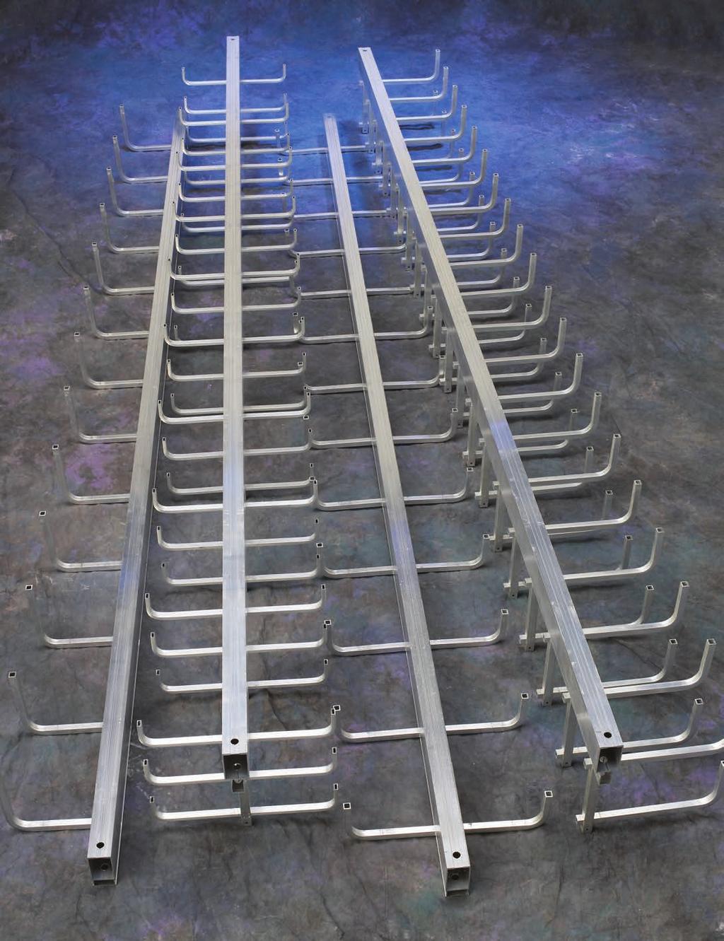
Cent-R-Rail Systems. WARNING: Do NOT use as a walkway, ladder or support for personnel. Cent-R-Rail. Cable Tray Systems
|
|
|
- Jessie Baldwin
- 6 years ago
- Views:
Transcription
1 114

2 How The Service Advisor Works Cooper B-Line knows that your time is important! That s why the color-coding system in this catalog is designed to help you select products that fit your service needs. Products are marked to indicate the typical lead time for orders of 50 pieces or less. Customer: How do I select my straight sections. covers, or fittings so that I get the quickest turnaround? Service Advisor: Each part of our selection chart is shown in colors. If any section of a part number is a different color, the part will typically ship with the longer lead time represented by the colors. Green = Fastest shipped items Black = Normal lead-time items Red = Normally long lead-time items Example: C0 A DB Part will have a normal lead time because of the C0 Series. 115
3 Systems Tray-To-Box Connector (pg. 154) 2. Center Rail End Cap (pg. 150) 3. HALF-RACK Straight Section (pg. 128) 4. Vertical Offset Coupling (pg. 134) 5. Horizontal Tee Coupling (pgs. 135 & 136) 6. MULTI-TIER HALF-RACK Straight Section (pg. 130) 7. MULTI-TIER HALF-RACK Add-A-Rung (pg. 130) 8. VERTI-RACK Straight Section (pg. 126) 9. Horizontal Cross Coupling (pg. 136) 10. Tray-To-Wall Connector (pg. 153) 11. Horizontal Offset Coupling (pg. 133) 12. Vertical Coupling (pg. 137) 13. DATA-TRACK Straight Section (pg. 124) 14. Horizontal Pivot Connector (pg. 139) 15. Cable Drop-Out (pg. 148) 16. VERTI-RACK Add-A-Rung (pg. 126) 17. Qwik-Bolt Splice Hanger (pg. 132) 18. Horizontal Adjustable Splice (pg. 134) 19. Universal Hub Fitting (pg. 138) 20. Vertical Adjustable Splice (pg. 137) 21. Clevis Hanger (pg. 140) WARNING: Do NOT use as a walkway, ladder or support for personnel. 116
4 Systems Data-Track Half-Rack Verti-Rack Multi-Tier Half-Rack Features Common to B-Line Systems: The fastest cable tray systems to install Sides and bottom are open for easy loading and inspection of cables Light-weight, high-strength, corrosion-resistant aluminum construction Provide the most freedom for cables to enter or exit - perfect for future change Cable fill area is free of sharp edges and connection hardware The splice can also be used to support the tray Qwik-Bolt splice maximizes installation speed and minimizes hardware Clevis hangers are available for random support locations without drilling center rail Systems are designed to install with 1 /2" ATR engineered to simplify the in-field drilling process and to provide post modification integrity All Systems use the same internal connectors All Systems are interactive with each other Designed to interact with B-Line s Strut System and Strut Raceway System Comprehensive accessory options allow for complete installations without traditional cable tray fittings Colored rung end caps are available for system labeling UL Classified (cross sectional area 0.60 in 2 /1000 amps) Patent Information The indicated patented products in this catalog are protected by one or more of the following patents. U.S. Patents 5,618,014; 5,628,481; 5,628,580; 5,634,614; 5,651,518; 5,564,658; 5,720,567; 5,730,400; 5,782,439; 5,816,542; 5,868,361; 6,547,192 U.K. Patents 2,285,344; 2,317,508; 2,317,509 Germany Patent 4,447,144 Canada Patent 2,139,201 Mexico-Pending 117
5 Systems Data-Track Half-Rack Ceiling hung or floor mounted Low profile Built-in barrier NEMA 12C load classification Seismic restraint systems available (see appendix page 172) CSA classified Technical information on pages 124 & 125 Sizes Available Loading depth: 3" (75), 4" (100), 6" (150) and straight rung Width: 6" (150), 9" (225), 12" (225), 18" (450), 24" (600) Length: 120" (3m), 144" (4m) Rung Spacing: 6" (150), 9" (225), 12" (300) Verti-Rack Supported on wall or other structure Low profile Flush mounted without spacers or brackets Seismic restraint systems available (see appendix page 172) CSA classified Technical information on pages 128 & 129 Sizes Available Loading depth: 3" (75), 4" (100), 6" (150) and straight rung Width: 3" (75), 6" (150), 9" (225), 12" (300) Length: 120" (3m), 144" (4m) Rung Spacing: 6" (150), 9" (225), 12" (300) Multi-Tier Half-Rack Ceiling hung Multiple tray runs with one center rail Installs in narrow spaces Provides cable system segregation NEMA 12C load classification Expandable with ADD-A-RUNG Expanded sizes available (page 173) Variable widths available (page 174) Inverted design available (page 175) Technical information on pages 126 & 127 Sizes Available Loading depth: Each tier 2" (50) and straight rung Width: 3" (75), 6" (150), 9" (225), 12" (300) Number of tiers: 2, 3, 4, 5 & 6 Length: 120" (3m), 144" (4m) Rung Spacing: 6" (150), 9" (225), 12" (300), specials available Supported on wall or other structure Multiple tray runs with one center rail Installs in narrow spaces Provides cable system segregation Flush mounted without spacers or brackets Expandable with ADD-A-RUNG Seismic restraint systems available (see appendix page 172) Variable widths available (page 174) Technical information on pages 130 & 131 Sizes Available Loading depth: 3" (75), 4" (100) and straight rung Width: 3" (75), 6" (150), 9" (225), 12" (300) Number of tiers: 2, 3 & 4 Length: 120" (3m), 144" (4m) Rung Spacing: 6" (150), 9" (225), 12" (300), specials available Dimensions shown in parentheses are in millimeters, unless otherwise specified. 118
6 Sizing Guide The following guidelines are based on the 1999 National Electrical Code, Article 318. I) Number of Multiconductor Cables, Rated 2000 Volts or Less, in Data-Track and Half-Rack (Excluding Straight Rung) (1) Multiconductor Control and/or Signal Cables Only A ladder cable tray containing only control and/or signal cables, may have 50% of its total fill area filled with cable. When using continuous bottom pans, the allowable fill is reduced from 50% to 40%. Example: Cable tray width is obtained as follows: 2/C - #16 AWG instrumentation cable cross sectional area = 0.04 sq. in. Total Cross Sectional Area for 300 Cables = sq. in. Minimum tray fill area needed = x 2 = sq. in.; therefore, the tray width required for 4" loading depth tray = 24.00/4 = 6 inches. (2) 4/0 or Larger Cables The ladder cable tray must have an inside usable width equal to or greater than the sum of the diameters (Sd) of the cables, which must be installed in a single layer. When using continuous bottom pans, the sum of the cable diameters can not exceed 90% of the usable tray width. Example: Cable tray width is obtained as follows: (D) (N) Multiply (D) x (N) List Cable List = Subtotal of the List Outside Number Sum of the Cable Cable Sizes Diameter of Cables Diameters 3/C - #500 kcmil 2.26 inches inches 3/C - #250 kcmil 1.76 inches inches 3/C - #4/0 AWG 1.55 inches inches The sum of the diameters (Sd) of all cables = = inches; therefore, a cable tray with a usable width of at least 12 inches is required. (3) Cables Smaller Than 4/0 The total sum of the cross-sectional areas of all the cables to be installed in the cable tray must be equal to or less than the allowable cable area for the tray width, as indicated in Table 1. When using continuous bottom pans, the allowable cable area is reduced by 22%. Example: Cable tray width is obtained as follows: (A) (N) Multiply (A) x (N) List Cable List = Total of the List Cross Sectional Number Cross-Sectional Cable Sizes Areas of Cables Area for Each Size 3/C - #12 AWG sq. in sq. in. 4/C - #12 AWG sq. in sq. in. 3/C - # 6 AWG sq. in sq. in. 3/C - # 2 AWG sq. in sq. in. Table 1 Inside Allowable Width of Cable Cable Area Tray square inches inches The sum of the totals of the cross-sectional areas = = inches. Using Table 1, a 12 inch wide tray with an allowable cable area of 14 sq. inches should be used. Note: Increasing the cable tray loading depth does not permit an increase in cable fill area for power and lighting cables. The maximum allowable fill area for all cable tray with a 3 inch or greater loading depth is limited to the fill area for a 3 inch loading depth. 119
7 Sizing Guide (4) 4/0 or Larger Cables Installed with Cables Smaller than 4/0 The ladder cable tray needs to be divided into two zones (a barrier or divider is not required, but one can be used if desired) so that the No. 4/0 and larger cables have a dedicated zone, as they must be placed in a single layer. A direct method for determining the cable tray width is by figuring the cable tray widths that are required for each of the cable combinations, per steps (2) & (3); and then adding these widths together to select the proper cable tray width. Example: Cable tray width is obtained as follows: Part A- Width required for #4/0 AWG and larger multiconductor cables (D) (N) Multiply (D) x (N) List List Cable List = Subtotal of the Cable Sizes Outside Number Sum of the Cable Diameter of Cables Diameters (Sd) 3/C - #500kcmil 2.26 inches inches 3/C - #4/0 AGW 1.55 inches inches Cable tray width required for large cables = = 5.36 inches. Part B- Width required for multiconductor cables smaller than #4/0 AWG (A) (N) Multiply (A) x (N) List List Cable List = Total of the Cable Sizes Cross Sectional Number Cross-Sectional Areas of Cables Area for Each Size 3/C - #12 AWG sq. in sq. in. 3/C - #6 AWG sq. in sq. in. 3/C - #2 AWG sq. in sq. in. The sum of the total areas = = 6.71 sq. inches. From Table 1, the cable tray width required for small cables is 6 inches. The total cable tray width = = inches; therefore a 12 inch wide cable tray is required. II) Number of Single Conductor Cables, Rated 2000 Volts or Less, in DATA-TRACK and HALF-RACK (Excluding Straight Rung) Single conductor cables installed in cable tray must be 1/0 or larger, and they can not be installed with continuous bottom pans. (1) 1000 KCMIL or Larger Cables The sum of the diameters (Sd) of all single conductor cables shall not exceed the cable tray width. See Table 3, page 121. (2) 250 KCMIL to 1000 KCMIL Cables The total sum of the cross-sectional areas of all the cables to be installed in the cable tray must be equal to or less than the allowable cable area for the tray width, as indicated in Table 2. Table 2 Inside Allowable Width of Cable Cable Area Tray square inches inches
8 Sizing Guide (3) Cables 1/0 through 4/0 These conductors must be installed in a single layer. See Table 3. Note: It is the opinion of some that this practice may cause problems with unbalanced voltages. To avoid these potential problems, the cables for this type of cable tray wiring system should be bundled with ties. The bundle should contain the circuit s three phase conductors plus the neutral, if one is used. The single conductor cables should be firmly tied to the cable trays at intervals not greater than 6 feet. Table 3 Number of 600 Volt Single Conductor Cables that may be Installed in Ladder Cable Tray Single Outside Area Cable Tray Width Conductor Diameter Size in. sq. in. in. in. in. in. in. 1/ / / / Kcmil Kcmil Kcmil Kcmil Kcmil Cable diameters used are those for Oknite-Okolon 600 volt single conductor power cables. III) Sizing VertI-Rack and Multi-Tier Half-Rack Due to the unique nature of multiple-tier cable trays, there are no existing guidelines for sizing these types of cable trays. However, the following tables are provided to assist you in comparing the usable widths and fill areas for the different trays available. WARNING! Do Not Use As A Walkway, Ladder, Or Support For Personnel. Use Only As A Mechanical Support For Cables, Tubing and Raceways. Catalog Number: C3ADB STR SECTION Shipping Ticket: Mark Number: Purchase Order: D Minimum Area: 0.60 SQ. IN. Load Class: D1 179 KG/M 3 METER SPAN 1 of 1 09/15/ (618) CLASSIFIED This product is classified by Underwriters Laboratories, Inc. as to its suitability as an equipment grounding conductor only. 556E VENTILATED Reference File #LR36026 This cable tray label is attached to each straight section and fitting that is U.L. classified. U.L. assigned cross-sectional area is also stated in the loading charts in this catalog for each system. 121
9 Sizing Guide Usable Tray Width & Overall Outside Width: Data-Track Tray Width Usable Width Overall Outside Width Bottom Rung Top Rung Bottom Rung Top Rung in. (mm) in. (mm) in. (mm) in. (mm) in. (mm) 6 (150) 6 (150) 6 (150) 8.7 (220) 7.1 (180) 9 (225) 9 (225) 9 (225) 11.7 (295) 10.1 (250) 12 (300) 12 (300) 12 (300) 14.7 (375) 13.1 (335) 18 (450) 16 (400) 18 (450) 19.1 (485) 19.1 (485) 24 (600) 22 (550) 24 (600) 25.1 (630) 25.1 (630) Verti-Rack Tray Total Usable Width Overall Width 2 tier 3 tier 4 tier 5 tier 6 tier Outside Width in. (mm) in. (mm) in. (mm) in. (mm) in. (mm) in. (mm) in. (mm) 3 (75) 6 (150) 9 (225) 12 (300) 15 (381) 18 (450) 4.4 (110) 6 (150) 12 (300) 18 (450) 24 (600) 30 (750) 36 (900) 7.4 (190) 9 (225) 18 (450) 27 (675) 36 (900) 45 (1125) 54 (1350) 10.4 (265) 12 (300) 24 (600) 36 (900) 48 (1200) 60 (1500) 72 (1800) 13.4 (340) Half-Rack Tray Width Usable Width Overall Outside Width in. (mm) in. (mm) in. (mm) 3 (75) 3 (75) 5.2 (130) 6 (150) 6 (150) 8.2 (210) 9 (225) 9 (225) 11.2 (285) 12 (300) 12 (300) 14.2 (360) Multi-Tier Half-Rack Tray Total Usable Width Overall Width 2 tier 3 tier 4 tier Outside Width in. (mm) in. (mm) in. (mm) in. (mm) in. (mm) 3 (75) 6 (150) 9 (225) 12 (300) 4.7 (120) 6 (150) 12 (300) 18 (450) 24 (600) 7.7 (195) 9 (225) 18 (450) 27 (675) 36 (900) 10.7 (270) 12 (300) 24 (600) 36 (900) 48 (1200) 13.7 (350) 122
10 Tray Fill Area & Overall Outside Height: Loading Tray Fill Area Overall Outside Height Depth Width Bottom Rung Top Rung Bottom Rung Top Rung in. (mm) in. (mm) in. 2 (cm 2 ) in. 2 (cm 2 ) in. (mm) in. (mm) 6 (150) 18 (120) 18 (120) 9 (225) 27 (180) 27 (180) 3 (75) 12 (300) 36 (240) 36 (240) 3.7 (95) 6.1 (155) 18 (450) 49 (325) 54 (360) 24 (600) 67 (450) 72 (480) 6 (150) 24 (160) 24 (160) 9 (225) 36 (240) 36 (240) 4 (100) 12 (300) 48 (320) 48 (320) 4.7 (120) 7.1 (180) 18 (450) 65 (420) 72 (480) 24 (600) 89 (575) 96 (640) 6 (150) 36 (240) 36 (240) 9 (225) 54 (360) 54 (360) 6 (150) 12 (300) 72 (480) 72 (480) 6.7 (170) 9.1 (230) 18 (450) 98 ((630) 108 (700) 24 (600) 134 (865) 144 (930) Data-Track Loading Tray Fill Area Depth Width 2 tier 3 tier 4 tier 5 tier 6 tier in. (mm) in. (mm) in. 2 (cm 2 ) in. 2 (cm 2 ) in. 2 (cm 2 ) in. 2 (cm 2 ) in. 2 (cm 2 ) 3 (75) 12 (80) 18 (120) 24 (160) 30 (200) 36 (240) 2 (50) 6 (150) 24 (160) 36 (240) 48 (320) 60 (400) 72 (480) 9 (225) 36 (240) 54 (360) 72 (480) 90 (600) 108 (700) 12 (300) 48 (320) 72 (480) 96 (640) 120 (800) 144 (930) Verti-Rack Overall Outside Height 2 tier 3 tier 4 tier 5 tier 6 tier in. (mm) in. (mm) in. (mm) in. (mm) in. (mm) 9.3 (235) 13.3 (340) 17.3 (440) 21.3 (540) 25.3 (645) Half-Rack Multi-Tier Half-Rack Loading Tray Fill Overall Depth Width Area Outside Height in. (mm) in. (mm) in. 2 (cm 2 ) in. (mm) 3 (75) 4 (100) 6 (150) 3 (75) 9 (60) 6 (150) 18 (120) 9 (225) 27 (180) 12 (300) 36 (240) 3 (75) 12 (80) 6 (150) 24 (160) 9 (225) 36 (240) 12 (300) 48 (320) 3 (75) 18 (120) 6 (150) 36 (240) 9 (225) 54 (360) 12 (300) 72 (480) 3.7 (95) 4.7 (120) 6.7 (170) Loading Tray Fill Area Depth Width 2 tier 3 tier 4 tier in. (mm) in. (mm) in. 2 (cm 2 ) in. 2 (cm 2 ) in. 2 (cm 2 ) 3 (75) 18 (120) 27 (180) 36 (240) 3 (75) 6 (150) 36 (240) 54 (360) 72 (480) 9 (225) 54 (360) 81 (525) 108 (700) 12 (300) 72 (480) 108 (700) 144 (930) 3 (75) 24 (160) 36 (240) 48 (320) 4 (100) 6 (150) 48 (320) 72 (480) 96 (640) 9 (225) 72 (480) 108 (700) 144 (930) 12 (300) 96 (640) 144 (930) 192 (1240) Overall Outside Height 2 tier 3 tier 4 tier in. (mm) in. (mm) in. (mm) 11.3 (285) 17.3 (440) 23.3 (590) 123
11 - Straight Sections Data-Track Data-Track Straight Section with CAS-SB Splice Hanger shown Rung Spacing Loading Depth One CAS-SB Splice Hanger provided with each straight section For overall height and width dimension see pages 122 & 123 Patented (see page 117) Data-Track Straight Section Part Numbering C3 A DB Rung Series Material Type Spacing Width Length* C0 = Straight Rung A = Aluminum DB = Bottom Rung 06 = 6" 06 = 6" 144 = 144" C3 = 3" Loading Depth DT = Top Rung 09 = 9" 09 = 9" 120 = 120" C4 = 4" Loading Depth 12 = 12" 12 = 12" C6 = 6" Loading Depth 18 = 18" 24 = 24" * Actual tray lengths are 142" and 118" to allow for splice hangers 124
12 - Straight Sections Data-Track Load Capacities Tray Rung Support Span ft. (m) Rung * Avg. Empty Width Spacing 5 (1.5) 6 (1.8) 8 (2.4) 10 (3.0) 12 (3.7) Deflection Tray Weight in. (mm) in. (mm) lbs/ft (kg/m) lbs/ft (kg/m) lbs/ft (kg/m) lbs/ft (kg/m) lbs/ft (kg/m) Multiplier lbs/ft (kg/m) 6 (150) 646 (961) 448 (667) 252 (375) 161 (240) 112 (167) (2.05) 6 (150) 9 (225) 532 (793) 448 (667) 252 (375) 161 (240) 112 (167) (1.86) 12 (300) 400 (595) 400 (595) 252 (375) 161 (240) 112 (167) (1.79) 6 (150) 532 (793) 448 (667) 252 (375) 161 (240) 112 (167) (2.16) 9 (225) 9 (225) 354 (527) 354 (527) 252 (375) 161 (240) 112 (167) (1.93) 12 (300) 266 (396) 266 (396) 252 (375) 161 (240) 112 (167) (1.85) 6 (150) 400 (595) 400 (595) 252 (375) 161 (240) 112 (167) (2.28) 12 (300) 9 (225) 266 (396) 266 (396) 252 (375) 161 (240) 112 (167) (2.01) 12 (300) 200 (298) 200 (298) 200 (298) 161 (240) 112 (167) (1.90) 6 (150) 266 (396) 266 (396) 252 (375) 161 (240) 112 (167) (2.51) 18 (450) 9 (225) 178 (265) 178 (265) 178 (265) 161 (240) 112 (167) (2.17) 12 (300) 134 (199) 134 (199) 134 (199) 134 (199) 112 (167) (2.01) 6 (150) 200 (298) 200 (298) 200 (298) 161 (240) 112 (167) (2.75) 24 (600) 9 (225) 134 (199) 134 (199) 134 (199) 134 (199) 112 (167) (2.32) 12 (300) 100 (149) 100 (149) 100 (149) 100 (149) 100 (149) (2.13) Safety Factor = 1.5 for load capacities Data-Track For unbalanced load information see appendix page 171 For Seismic Restraint Systems see appendix page 172 Support Span (feet) Center Rail Deflection Multiplier* * Deflection multipliers are given for English units. To determine deflection in millimeters, first calculate deflection in inches and then multiply by To calculate the center rail simple beam deflection at mid span in inches for a specific support span (ft), multiply the center rail deflection multiplier for that span by the load in lbs/ft that will be installed in the cable tray. Example: The center rail deflection for 50 lbs/ft supported every 12 ft = 50 x.0397 = 2.0 inches. Note: When trays are used in continuous spans, the deflection is reduced by as much as 50%. To calculate the rung deflection in inches for a specific tray width (in.) and rung spacing (in.), multiply the rung deflection multiplier for that width and rung spacing by the load in lbs/ft that will be installed in the cable tray. Example: The rung deflection for 50 lbs/ft in a 12" wide tray with 9" rung spacing = 50 x.0002 =.01 inches. Note: The rung deflection multiplier is based on a uniformly distributed load. Section Property Center Rail Rungs Area in (cm 2 ) (5.68) (0.84) Sx in (cm 3 ) (11.49) (0.31) Ix in (cm 4 ) (48.87) (0.21) Center Rail 1.63" (41mm) 3.25" (82mm).54" (14mm) Rung.54" (14mm) 125
13 - Straight Sections Verti-Rack Verti-Rack Straight Section with CAS-SB Splice Hanger shown One CAS-SB Splice Hanger provided with each straight section For overall height and width dimension see pages 122 & 123 Patented (see page 117) Rung Spacing 1 3 /4" (44mm) Verti-Rack Straight Section Part Numbering C2 A 4V Rung Series Material Type Spacing Width Length* C0 = Straight Rung A = Aluminum 2V = 2 tier 06 = 6" 03 = 3" 144 = 144" C2 = 2" Loading Depth 3V = 3 tier 09 = 9" 06 = 6" 120 = 120" 4V = 4 tier 12 = 12" 09 = 9" 5V = 5 tier (Specials 12 = 12" 6V = 6 tier available) * Actual tray lengths are 142" and 118" to allow for splice hangers For inverted, multiple or special sizes and widths see appendix pages 173, 174, 175 Expand your Verti-Rack system with ADD-A-Rung Attaches to bottom of existing tray Shipped with required hardware ADD-A-Rung Part Numbering CAR-2 V 2 12 No. of Loading Tiers Depth Width 1 = 1 tier 0 = Straight Rung 03 = 3" 2 = 2 tier 2 = 2" Loading Depth 06 = 6" 09 = 9" 12 = 12" Note: Not to exceed 100 lbs/ft on 12 ft span, 225 lbs/ft on 8 ft span. 126
14 - Straight Sections Verti-Rack Support Total System Center Rail* Span Load Capacities Deflection ft (m) lbs/ft (kg/m) Multiplier 5 (1.5) 300 (450) (1.8) 300 (450) (2.4) 225 (335) (3.0) 144 (214) (3.7) 100 (149) Tray Rung Per Tier Rung* Avg. Empty Width Spacing Load Capacity Deflection Tray Weight in. (mm) in. (mm) lbs/ft (kg/m) Multiplier lbs/ft (kg/m) 6 (150) 608 (905) (3.11) 3 (75) 9 (225) 408 (607) (2.56) 12 (300) 304 (452) (2.31) 6 (150) 304 (452) (3.44) 6 (150) 9 (225) 204 (304) (2.77) 12 (300) 152 (226) (2.47) 6 (150) 203 (302) (3.76) 9 (225) 9 (225) 136 (202) (2.98) 12 (300) 102 (152) (2.63) 6 (150) 152 (226) (4.09) 12 (300) 9 (225) 102 (152) (3.18) 12 (300) 76 (113) (2.80) Safety Factor = 1.5 for load capacities * Deflection multipliers are given for English units. To determine deflection in millimeters, first calculate deflection in inches and then multiply by Example: The center rail deflection for 50 lbs/ft supported every 12 ft = 50 x.0321 = 1.6 inches. Example: The rung deflection for 50 lbs/ft in a 12" wide tray with 9" rung spacing = 50 x.0009 =.05 inches. Section Property Center Rail Rungs Trunk Area in (cm 2 ) (5.68) (0.61) (1.16) Sx in N/A (cm 3 ) (9.15) (0.12) (N/A) Ix in N/A (cm 4 ) (52.99) (0.04) (N/A) Center Rail Trunk Rung (41mm) (18mm) (14mm) 1.63".71".54".71" (18mm).31" (8mm) 3.90" (99mm) 127
15 - Straight Sections Half-Rack Half-Rack Straight Section with CAS-SB Splice Hanger shown Rung Spacing One CAS-SB Splice Hanger provided with each straight section For overall height and width dimension see pages 122 & 123 Loading Depth Patented (see page 117) Half-Rack Straight Section Part Numbering C3 A 1H Rung Series Material Type Spacing Width Length* C0 = Straight Rung A = Aluminum 1H = 1 tier 06 = 6" 03 = 3" 144 = 144" C3 = 3" Loading Depth 09 = 9" 06 = 6" 120 = 120" C4 = 4" Loading Depth 12 = 12" 09 = 9" C6 = 6" Loading Depth 12 = 12" * Actual tray lengths are 142" and 118" to allow for splice hangers 128
 (12') Length Section Mid Length * = 20\" (508mm) for 120\" (3m) Length Section Sections should be attached to the wall at mid length and at 1 /6th of the section length from both ends (20\" for")
16 - Straight Sections Half-Rack Half-Rack Loading Guidelines Support Locations 1" (25mm) *24" (609mm) 144" (3.7m) (12') Length Section Mid Length * = 20" (508mm) for 120" (3m) Length Section Sections should be attached to the wall at mid length and at 1 /6th of the section length from both ends (20" for 120"; 24" for 144") No spacers needed For Half-Rack wall attachment options see page 164 *24" (609mm) Loading Recommendations CSA classified A-3M 50 lbs/ft (74kg/m) maximum based on 3 /4" (19mm) rung deflection Section Property Center Rail Rungs Area in (cm 2 ) (5.68) (0.84) Center Rail (41mm) 1.63" Rung (14mm).54".54" (14mm) Sx Ix in (cm 3 ) (11.49) (0.31) in (cm 4 ) (52.99) (0.21) 3.25" (82mm) 129
17 - Straight Sections A Multi-Tier Half-Rack Straight Section with CAS-SB Splice Hanger shown A = 2 5 /8" (67mm) for 3" (76mm) Loading Depth = 1 3 /4" (44mm) for 4" (102mm) Loading Depth One CAS-SB Splice Hanger provided with each straight section For overall height and width dimension see pages 122 & 123 Rung Spacing Patented (see page 117) Loading Depth Multi-Tier Half-Rack Straight Section Part Numbering C3 A 2M Rung Series Material Type Spacing Width Length* C0 = Straight Rung A = Aluminum 2M = 2 tier 06 = 6" 03 = 3" 144 = 144" C3 = 3" Loading Depth 3M = 3 tier 09 = 9" 06 = 6" 120 = 120" C4 = 4" Loading Depth 4M = 4 tier 12 = 12" 09 = 9" (Specials 12 = 12" available) * Actual tray lengths are 142" and 118" to allow for splice hangers For multiple widths see appendix pages 173 & 174 Expand your Multi-Tier Half-Rack system with ADD-A-Rung Attaches to bottom of existing tray Shipped with required hardware ADD-A-Rung Part Numbering CAR-2 M 3 12 No. of Loading Tiers Depth Width 1 = 1 tier 0 = Straight Rung 03 = 3" 2 = 2 tier 3 = 3" Loading Depth 06 = 6" 4 = 4" Loading Depth 09 = 9" 12 = 12" Note: Not to exceed 100 lbs/ft on 12 foot spans and 225 lbs/ft on 8 foot spans 130
18 Multi-Tier Half-Rack Multi-Tier Half-Rack Loading Guidelines Support Locations 1" (25mm) *24" (609mm) 144" (3.7m) (12') Length Section Mid Length *24" (609mm) * = 20" (508mm) for 120" (3m) Length Section Sections should be attached to the wall at mid length and at 1 /6th of the section length from both ends (20" for 120"; 24" for 144") No spacers needed For Multi-Tier Half-Rack wall attachment options see page 165 Loading Recommendations 50 lbs/ft (74kg/m) maximum based on 3 /4" (19mm) rung deflection Half-Rack shown For Seismic Restraint Systems see appendix page 172 Section Property Center Rail Rungs Trunk Area in (cm 2 ) (5.68) (0.84) (1.16) Sx in N/A (cm 3 ) (9.15) (0.31) (N/A) Center Rail Trunk Rung (41mm) (18mm) (14mm) 1.63".71".54".71" (18mm).54" (8mm) Ix in N/A (cm 4 ) (52.99) (0.21) (N/A) 3.90" (99mm) 131
19 - Connectors Application System Icons The parts in the following catalog sections can be used with one or more of the systems. We have provided the following application icons to indicate the systems each item is compatible with. Compatibility with Data-Track Compatibility with VertI-Rack Compatibility with Half-Rack Shaded items shown in the illustrations are items that are provided with the part numbers. Compatibility with Multi-Tier Half-Rack Qwik-Bolt Splice Hanger CAS-SB Patented (see page 117) One splice included with each straight section Bolts screw directly into splice, minimizing hardware Splice protects cables from center rail edges Vertical hardware removes hardware from cable fill area Shipped assembled with required hardware Designed to install with 1 /2" ATR UL classified for grounding amps Qwik-Bolt No Gap Splice CAS-NG1 Patented (see page 117) A straight splice option Bolts screw directly into splice, minimizing hardware Vertical hardware removes hardware from cable fill area Shipped assembled with required hardware UL classified for grounding amps Straight section length (using this splice) is 142 or 118 inches For use where ATR is not required through the splice hanger Note: All connectors are aluminum material and sized for 1 /2" zinc plated steel hardware, unless otherwise specified. 132
20 - Connectors Qwik-Bolt Splice Hanger CAS-CB Patented (see page 117) Side mounts to existing 1 /2" ATR Qwik-Bolt design Shipped with required hardware UL classified for grounding amps Expansion Splice Hanger CAS-EB1 Tray Type Data-Track & Half-Rack CAS-EB2 Verti-Rack & Multi-Tier Half-Rack Table 1 Patented (see page 117) Allows for 1" (25mm) of tray expansion and contraction Shipped with required hardware Order grounding jumper CAM-GJ separately (see page 148) It is important that thermal contraction and expansion be considered when installing cable tray systems. The length of the straight cable tray runs and the temperature differential govern the number of expansion splice plates required (See Table 1). Horizontal Offset Coupling Offset in. (mm) Maximum Spacing Between Expansion Joints that Provide for 1" (25mm) Movement Temperature Aluminum Differential F ( C) ft (m) 25 (14) 260 (79) 50 (28) 130 (40) 75 (42) 87 (27) 100 (56) 65 (20) 125 (69) 52 (16) 150 (83) 43 (13) 175 (97) 37 (11) offset CAC-OH050B 5.0 (125) CAC-OH065B 6.5 (165) CAC-OH080B 8.0 (200) CAC-OH100B 10.0 (250) CAC-OH130B 13.0 (330) Patented (see page 117) Refer to tray widths on pg. 122 to determine offset needed Designed to provide horizontal offset Ideal for connecting Data-Track to Half-Rack Pivoting connections Qwik-Bolt design Shipped assembled with required hardware UL classified for grounding amps 7 /8" (22mm) adjustment on offset Note: All connectors are aluminum material and sized for 1 /2" zinc plated steel hardware, unless otherwise specified. 133
21 - Connectors Vertical Offset Coupling Patented (see page 117) Offset in. (mm) CAC-OV030B 3.0 (75) CAC-OV060B 6.0 (150) Designed to provide vertical offset Pivoting connections Qwik-Bolt design Shipped assembled with required hardware UL classified for grounding amps offset Horizontal Adjustable Splice CAS-HB Patented (see page 117) Allows random angle horizontal bend Also can be used to connect straight sections at mid-run locations Qwik-Bolt design Shipped assembled with required hardware UL classified for grounding amps Horizontal Bend Rung Support CAR-H3-06 CAR-H3-09 CAR-H3-12 CAR-H3-18 CAR-H3-24 CAR-H4-06 CAR-H4-09 CAR-H4-12 CAR-H4-18 CAR-H4-24 CAR-H6-06 CAR-H6-09 CAR-H6-12 CAR-H6-18 CAR-H6-24 CAR-H3-06 Loading Tray Depth Width 3 = 3" 06 = 6" 4 = 4" 09 = 9" 6 = 6" 12 = 12" 18 = 18" 24 = 24" Patented (see page 117) Use with CAS-HB For additional cable support on the outside of bends Select fill depth and width required Shipped with required hardware (1 pc. HHCS - 1 /2" x 4" znplt) Rungs set at 45 angle Note: All connectors are aluminum material and sized for 1 /2" zinc plated steel hardware, unless otherwise specified. 134
22 - Connectors Data-Track L Patented (see page 117) Tray 1 Tray 1 Width L in. (mm) in. (mm) 6 (150) CAC-HTD06B 5 (125) 9 (225) CAC-HTD09B 6 1 /2 (165) 12 (300) CAC-HTD12B 8 (200) 18 (450) CAC-HTD18B 10 (250) 24 (600) CAC-HTD24B 13 (330) Used to make tee, elbow or wye Allows random attachment to center rail without drilling Pivoting connection Qwik-Bolt Design Shipped assembled with required hardware 9 /16" (14mm) hole provided for optional support ATR 7 /16" (11mm) adjustment slot UL classified for grounding amps L Tray 1 Patented (see page 117) Tray 1 L Patented (see page 117) Verti-Rack Horizontal Tee Coupling Tray 1 Width L in. (mm) in. (mm) 3 (75) CAC-HTV03B 3 (75) 6 (150) CAC-HTV06B 4 1 /2 (115) 9 (225) CAC-HTV09B 6 (150) 12 (300) CAC-HTV12B 7 1 /2 (190) Used to make tee, elbow or wye Allows random attachment to center rail without drilling Pivoting connection Qwik-Bolt design Shipped assembled with required hardware 7 /16" (11mm) adjustment slot UL classified for grounding amps Half-Rack Horizontal Tee Coupling Tray 1 Width L in. (mm) in. (mm) 3 (75) CAC-HTH03B 5 (125) 6 (150) CAC-HTH06B 8 (200) 9 (225) CAC-HTH09B 11 (275) 12 (300) CAC-HTH12B 14 (355) Used to make tee, elbow or wye Allows random attachment to center rail Pivoting connection Qwik-Bolt design Shipped assembled with required hardware UL classified for grounding amps Note: All connectors are aluminum material and sized for 1 /2" zinc plated steel hardware, unless otherwise specified. 135
23 - Connectors Multi-Tier Half-Rack Horizontal Tee Coupling Tray 1 Tray 1 Width L in. (mm) in. (mm) 3 (75) CAC-HTM03B 5 (125) 6 (150) CAC-HTM06B 8 (200) 9 (225) CAC-HTM09B 11 (275) 12 (300) CAC-HTM12B 14 (355) L Used to make tee, elbow or wye Allows random attachment to center rail Pivoting connection Qwik-Bolt design Shipped assembled with required hardware UL classified for grounding amps Patented (see page 117) Data-Track Horizontal Cross Coupling Tray 1 Width L in. (mm) in. (mm) 6 (150) CAC-HXD06B 10 (250) 9 (225) CAC-HXD09B 13 (330) 12 (300) CAC-HXD12B 16 (400) 18 (450) CAC-HXD18B 20 (500) 24 (600) CAC-HXD24B 26 (650) Allows random attachment to center rail without drilling Pivoting connections Qwik-Bolt design Shipped assembled with required hardware 9 /16" (14mm) hole provided for optional support ATR UL classified for grounding amps L Patented (see page 117) Tray 1 Verti-Rack Horizontal Cross Coupling Tray 1 Width L in. (mm) in. (mm) 3 (75) CAC-HXV03B 3 (75) 6 (150) CAC-HXV06B 9 (225) 9 (225) CAC-HXV09B 12 (300) 12 (300) CAC-HXV12B 15 (375) Allows random attachment to center rail without drilling Pivoting connections Qwik-Bolt design Shipped assembled with required hardware 9 /16" (14mm) hole provided for optional support ATR UL classified for grounding amps L Patented (see page 117) Tray 1 Note: All connectors are aluminum material and sized for 1 /2" zinc plated steel hardware, unless otherwise specified. 136
24 - Connectors Vertical Adjustable Splice CAS-VB Patented (see page 117) Ideal for random angle vertical bends Qwik-Bolt design Shipped assembled with required hardware UL classified for grounding amps Vertical Coupling CAC-VB Patented (see page 117) Use one piece to create vertical tees. Use two pieces to create vertical crosses. Pivoting connections Qwik-Bolt design Shipped assembled with required hardware UL classified for grounding amps Note: All connectors are aluminum material and sized for 1 /2" zinc plated steel hardware, unless otherwise specified. 137
25 - Connectors Universal Hub Fittings U2A-06 U2A-09 U2A-12 U2A-18 U2A-24 U3A-06 U3A-09 U3A-12 U3A-18 U3A-24 U4A-06 U4A-09 U4A-12 U4A-18 U4A-24 U6A-06 U6A-09 U6A-12 U6A-18 U6A-24 U4A-12 Fill Depth Width 2 = 2" 06 = 6" 3 = 3" 09 = 9" 4 = 4" 12 = 12" 6 = 6" 18 = 18" 24 = 24" Fill Depth Patented (see page 117) Width Connects up to 4 trays in random directions Provides an area free of center rails for cable transitions Ideal for easy system expansion Slots provided for cable tie down Order one CAC-UFB pivot connector per tray connection (see page 139) Positive cable retention for cables routed around corner post UL classified for grounding amps Typical applications for universal hub fittings: Elbow Tee Cross Wye Note: All connectors are aluminum material and sized for 1 /2" zinc plated steel hardware, unless otherwise specified. 138
26 - Connectors Pivot Connector For Universal Hub Horizontal Application CAC-UFB Patented (see page 117) Qwik-Bolt design Shipped with required hardware UL classified for grounding amps Category 5 Cable Radius Protector Tray Depth CAM-PR253 3 CAM-PR254 4 CAM-PR256 6 Designed to provide a 2 1 /2" cable bend radius Mounts directly over the horizontal pivot connector using the existing hardware Made from aluminum Note: All connectors are aluminum material and sized for 1 /2" zinc plated steel hardware, unless otherwise specified. 139
27 - Supports Data-Track Standard Clevis Hanger Rod Size CZNH-CD 1/2 CZNH-CD- 5 /8 5/8 Allows random support without drilling Zinc plated steel construction If seismic restraints required, see Seismic Restraints Supplement brochure (SRSCR1) Verti-Rack Standard Clevis Hanger Rod Size CZNH-CV 1/2 CZNH-CV- 5 /8 5/8 Allows random support without drilling Zinc plated steel construction Note: All connectors are aluminum material and sized for 1 /2" zinc plated steel hardware, unless otherwise specified. 140
28 - Supports Wall Hanger Half Rack CZNH-WH Simplifies bolt to anchor alignment. Center rail drilling eliminated. Hanger bottom snaps over center rail. Smooth edge design in wire fill areas. Zinc plated steel construction Sized for up to a 1 /2" bolt. Wall Hanger Multi-Tier Half Rack CZNH-WM Simplifies bolt to anchor alignment. Center rail drilling eliminated. Hanger bottom snaps over center rail. Smooth edge design in wire fill areas. Zinc plated steel construction Sized for up to a 1 /2" bolt. U-Bracket: In Drywall & Metal Stud Wall CPB-U10 CPB-CV1 Tray Type Half-Rack Multi-Tier Half-Rack Flat Washers CPB-U10 U-Bracket 1/4" Metal Screws Half-Rack Cable Tray Metal Stud Note: All connectors are aluminum material and sized for 1 /2" zinc plated steel hardware, unless otherwise specified. 141
29 - Supports Floor Stands Cat. Height Width No. in. (mm) in. (mm) B /8 (60.3) 6 (152.4) B /8 (111.1) 8 (203.2) B /8 (161.9) 10 (254.0) B /8 (212.7) 12 (304.8) B /8 (263.5) 14 (355.6) Height 13/16" (21mm) Zinc plated steel construction 9 /16" (14mm) holes Width Relay Rack Mounting Bracket SB-2133-CR ASTM A36 Steel Yellow zinc dichromate Includes: Mounting plates 1-1 /2" x 4 1 /2" HHCS 1-1 /2" hex nut 2-5 /16" x 3" SRHMS 2-5 /16" hex nuts 2-5 /16" lockwashers Note: All connectors are aluminum material and sized for 1 /2" zinc plated steel hardware, unless otherwise specified. 142
30 - Support Accessories Zinc Plated Steel Zinc Plated Steel Zinc Plated Steel Square Washer U Washer 90 Angle Fitting B202 B450 B101 Zinc Plated Steel Aluminum Aluminum Wall Bracket B370 Z Bracket B110AL Z Bracket CAB-U25 Zinc Plated Steel U Bracket B107 U Bracket B107-22A Zinc Plated Steel U Bracket CAB-U10 Aluminum Zinc Plated Steel Aluminum Zinc Plated Steel U Bracket CAB-U20 U Bracket B594 Post Base B281ASQ 143
31 - Support Accessories Non-Uniform Loading Bracket ATR Length CZN-DRS CZN-DRS CZN-DRS Hardware included ATR included Zinc plated See Seismic Restraints Supplement brochure (SRSCR1) Note: Refer to unbalance section in the appendix (pg. 171) Includes: 1 - B107 Znplt U Support 1 - B107-22A Znplt U Support 9-1 /2" Hex Nuts, Znplt 2 - ATR 1 /2" x Length, Znplt 1 - HHC Screw 1 /2" x 4 1 /2", Znplt 2 - B202 Znplt sq washers All Threaded Rod Stiffener See Seismic Restraints Supplement brochure (SRSCR1) Note: Minimum of (2) - SC228 or SC-UB are required per rod. SC228 Maximum distance from top of hanger rod to first bolt of the channel rod stiffener is 6" (152mm). 1/2" ATR SC228 Hanger Rod Stiffener Assembly For 3 /8" thru 5 /8" ATR (Order B22 Channel Separately) Maximum distance between each SC228 is 18" (457mm). SC228 Hanger Rod Stiffener Assembly B22 Channel Rod Stiffener 1/2" ATR Maximum distance from top of channel where the hanger rod is attached to the first bolt of the channel rod stiffener is 6" (152mm). B22 Channel Rod Stiffener with SC228 Assemblies 144
32 - Support Accessories Channel Sizes and Hole Patterns Selections Chart Channel Channel Material & Thickness Channel Hole Patterns Type Dimensions SH S H1 7 /8 TH Height Width in. (mm) in. (mm) Steel Alum. 304 S.S. 316 S.S. B /4 (82.5) 1 5 /8 (41.3) 12Ga B22A 3 1 /4 (82.5) 1 5 /8 (41.3) 12Ga Ga. 12Ga. 1,2,3,4 1 1,2,3,4 -- B /8 (41.3) 1 5 /8 (41.3) 12Ga Ga. 12Ga. 1,2,3,4 1 1,2,3,4 1 B54 15/16 (20.6) 1 5 /8 (41.3) 14Ga Ga. 14Ga. 1,2,3,4 1 1,2,3,4 -- Available Finishes on Steel: Dura-Green Epoxy, Pre-Galvanized and Hot Dip Galvanized are standard. Material types available for various hole patterns are defined by numbers 1 thru 4 as follows: 1= Steel 2= Aluminum 3= Type 304 Stainless Steel 4= Type 316 Stainless Steel With Spring Without Spring Twirl Nut Thread Thickness Size B11 B22 B42 B11, B22 B42 B11, B22 B42 B12 B24 B52 B12, B24 B52 B12, B24 B52 B32 B54 B32 B54 B32 B54 Channel Nuts N725 N225 N525 N225WO N525WO TN225 TN525 1 /2"-13 1 /2"(12.7 mm) for N725,N225,N225WO,TN225 3/8"(9.5 mm) for N525,N525WO,TN525 N755 N255 N555 N255WO N555WO /8"-11 1 /2"(12.7 mm) for N755,N255,N255WO 3/8"(9.5 mm) for N555,N555WO Channel Nut With Spring Channel Nut Without Spring Twirl Nut Threads *Recommended Load & Size Per Inch lbs (kn) ATR 1 /2" (5.02) ATR 5 /8" (8.05) *Safety Factor = 5 Specify length in inches: 36", 72", 120", 144" All Threaded Rod (ATR) Flat Washers & Size FW 1/2" FW 5/8" Hex Nut & Size HN 1/2" HN 5/8" 145
33 - Support Accessories Rod Coupling Reducer Rod Coupling Cat. Recommended No. Size Length Load in. (mm) in. (mm) B655-1 /2 1 /2" /4" (44.4) 1130 (5.02) B655-5 /8 5 /8" /8" (54.0) 1610 (8.05) Catalog Recommended Number Size Length Load in. (mm) in. (mm) B656-1 /2 x 3 /8 1 /2"-13 & 3 /8" /4" (31.7) 610 (2.71) B656-5 /8 x 3 /8 5 /8"-11 & 1 /2" /4" (31.7) 1130 (5.02) B656-3 /4 x 5 /8 3 /4"-10 & 5 /8" /2" (38.1) 1810 (8.05) Sleeve Anchors Hex Nut Type Round Quadrex Hex Nut Round Quadrex Catalog Bolt Hole Number Size Diameter Diameter in. (mm) in. (mm) in. (mm) ASA HN 1 /2 x 2 1 /4 (12.7 x 57.1) 3 /8 (9.5) 1 /2 (12.7) ASA HN 1 /2 x 4 (12.7 x 101.6) 3 /8 (9.5) 1 /2 (12.7) ASA HN 5 /8 x 2 1 /4 (15.9 x 57.1) 1 /2 (12.7) 5 /8 (15.9) ASA HN 5 /8 x 4 1 /4 (15.9 x 107.9) 1 /2 (12.7) 5 /8 (15.9) ASA RQ 3 /8 x 2 1 /2 (9.5 x 63.5) 5 /16 (7.9) 3 /8 (9.5) ASA RQ 3 /8 x 3 3 /4 (9.5 x 95.2) 5 /16 (7.9) 3 /8 (9.5) ASA RQ 3 /8 x 4 3 /4 (9.5 x 120.6) 5 /16 (7.9) 3 /8 (9.5) Catalog Minimum Allowable Pull- Allowable Number Embedment Out Load* Shear Load* in. (mm) lbs (kn) lbs (kn) ASA HN 1 1 /2 (38.1) 1100 (4.8) 1100 (4.8) ASA HN 1 1 /2 (38.1) 1100 (4.8) 1100 (4.8) ASA HN 2 (50.8) 1545 (6.8) 1790 (7.8) ASA HN 2 (50.8) 1545 (6.8) 1790 (7.8) ASA RQ 1 1 /4 (31.7) 675 (2.9) 550 (2.5) ASA RQ 1 1 /4 (31.7) 675 (2.9) 550 (2.5) ASA RQ 1 1 /4 (31.7) 675 (2.9) 550 (2.5) * Tested in 3500 PSI (24.0 MPa) concrete. S.F. = 4.0 Catalog Anchor Size Thread Hole Number Diameter Length Depth Diameter in. (mm) in. (mm) in. (mm) in. (mm) ADI-50 1 /2 (12.7) 2 (50.8) 13 /16 (20.6) 5 /8 (15.9) ADI-62 5 /8 (15.9) 2 1 /2 (63.5) 1 3 /16 (30.2) 7 /8 (22.2) Drop-In Anchors Catalog Anchor Allowable Allowable Setting Tool Number Length Pull-Out Load* Shear Load* in. (mm) lbs (kn) lbs (kn) ADI-50 2 (50.8) 1883 (8.2) 1903 (8.3) ADI-50T ADI /2 (63.5) 2473 (10.8) 3403 (14.9) ADI-62T * Tested in 4800 PSI (33.5 MPa) concrete. S.F. =
34 - Support Accessories Beam Clamps Cat. Rod No. Size B C D in. (mm) in. (mm) B307 1/2"-13 1 /2" /16" (61.9) 7/8" (22.2) B308 1/2"-13 1 /2" /16" (65.1) 7/8" (22.2) B /2"-13 1 /2" /16" (90.5) 1 11 /16" (42.8) C D E B Cat. Design No. E F T Load in. (mm) in. (mm) in. (mm) lbs. (kn) B /8" (28.6) 2 1 /2" (63.5) 7Ga. (4.5) 1100 (4.89) B /8" (28.6) 2 1 /2" (63.5) 1/4" (6.3) 1500 (7.11) B /8" (41.3) 3 1 /4" (82.5) 1/4" (6.3) 1400 (6.23) F T Design Load Safety Factor = 5 Setscrew included Anchor Strap Flange Width in. (mm) B312-6 Up to 6" (Up to 152.4) B "-9" ( ) B "-12" ( ) Beam Clamp Part Design Max. Mat l Number Load* Flange Thick Thickness lbs (kn) in. (mm) in. (mm) B212-3 / (4.45) 1 1 /8 (28.6) 3/8 (9.5) *when used in pairs Used with B307, B308 and B321-2 beam clamps Design Load Safety Factor = 5 Sold in pieces Setscrew included Beam Clamp Cat. Design A No. Load* Dimension lbs (kn) in. (mm) B (15.34) 3 3 /8 (85.7) B441-22A 1200 (15.34) 5 (127.0) B441Z-22 N/A (N/A) 3 3 /8 (85.7) *when used in pairs Design Load Safety Factor = 5 Sold in pieces Beam Clamps B355 Design Load 1200 lbs (5.34kN) when used in pairs Design Load Safety Factor = 5 Sold in pieces Order HHCS & channel nuts separately 147
35 - Accessories Cable Drop-Out Cat. No. A in. Provides 3.25" (82mm) bend radius Attaches to horizontal section of rung Self-drilling screw included Part number for one side only A CAM-DO-1 1 CAM-DO-2 2 CAM-DO CAM-DO-3 3 CAM-DO-4 4 CAM-DO-5 5 CAM-DO CAM-DO-7 7 CAM-DO-8 8 CAM-DO CAM-DO Tray Recommended Drop-out Width A* Width DATA-TRACK DATA-TRACK Half-Rack Multi-Tier in. Bottom Rung Top Rung Half-Rack Verti-Rack 3 N/A N/A N/A N/A N/A N/A N/A N/A *Indicates widest Drop-out that will fit in tray Grounding Jumper CAM-GJ Tin plated copper 1000 Amps maximum fuse amperage rating 12" (305mm) overall length Provides electrical continuity between trays Required with expansion splice hangers and when trays are discontinuous For up to 1 /2" hardware - not provided 148
36 - Accessories Pan Solid floor system with the flexibility of a center rail system Side remains open for cable exit/entry Available in aluminum or pre-galvanized steel Shipped with self-drilling screws for easy field installation (Pan shown in Data-Track ) Tray Pan Catalog Number Width Data-Track Data-Track Verti-Rack Half-Rack Multi-Tier in. Bottom Rung Top Rung (one side - Half-Rack (one side only) (one side only) one tier only) (one tier only) 3 N/A N/A C(*)P-008-( ) C(*)P-020-( ) C(*)P-020-( ) 6 C(*)P-020-( ) C(*)P-012-( ) C(*)P-023-( ) C(*)P-050-( ) C(*)P-050-( ) 9 C(*)P-035-( ) C(*)P-027-( ) C(*)P-038-( ) C(*)P-080-( ) C(*)P-080-( ) 12 C(*)P-050-( ) C(*)P-042-( ) C(*)P-053-( ) C(*)P-110-( ) C(*)P-110-( ) 18 C(*)P-072-( ) C(*)P-072-( ) N/A N/A N/A 24 C(*)P-102-( ) C(*)P-102-( ) N/A N/A N/A (*) Material- Insert A for.040 aluminum or P for 20 Ga. pre-galvanized steel. ( ) Length- Insert 060 for 60", 072 for 72", 120 for 120", or 144 for 144". Ordering information - Example: CAP Aluminum pan for 9" wide bottom rung Data-Track in a 12 foot section. 149
37 - Accessories Plastic Center Rail End Cap Plastic Center Rail End Cap CPLM-EC10-Gray CPLM-EC20-Gray Fits over end of center rail Gray PVC material Field installation Fits over end of center rail Gray PVC material Field installation 4 Deep only Up to 2 Deep only Plastic Rung End Cap Plastic Rung End Cap CPLM-EC30-* * Insert color: Gray is standard Optional- red, white, purple, blue, yellow, orange, black CPLM-EC40-* * Insert color: Gray is standard Optional- red, white, purple, blue, yellow, orange, black Fits over end of rungs Used for cable identification PVC material Field installation Fits over end of rungs Used for cable identification PVC material Field installation 150
38 - Accessories Plastic Trunk End Cap CPLM-EC50-Gray Fits over end of vertical trunk Gray PVC Material Field installation Conduit Adapter Designed to support or suspend light-duty stationary conduit runs Zinc plated steel Attaches to tray center rail (mounting hardware not included) Mounting Conduit Hardware Size Size in. (mm) in. (mm) BL1400 1/2 (15) 1/4 (6) BL1410 3/4 (20) 1/4 (6) BL (25) 1/4 (6) BL /4 (32) 1/4 (6) BL /2 (40) 5/16 (8) BL (50) 5/16 (8) BL /2 (65) 5/16 (8) BL (80) 5/16 (8) BL /2 (90) 5/16 (8) BL (100) 5/16 (8) Conduit Adapter Connects conduit to Easy one rung installation Positions conduit between rungs Shipped assembled with hardware Conduit Size in. (mm) BL1400-C442 1/2 (15) BL1410-C442 3/4 (20) BL1420-C442 1 (25) BL1430-C /4 (32) BL1440-C /2 (40) BL1450-C442 2 (50) 151
39 - Accessories 6" (152mm) thru 12" (305mm) rung spacing 18" (457mm) thru 24" (609mm) rung spacing Conduit Adapter Conduit Size Punched in. (mm) CAM-CA1S- 1 /2 1/2 (15) CAM-CA1S- 3 /4 3/4 (20) CAM-CA1S-1 1 (25) CAM-CA1S-1 1 /4 1 1 /4 (32) CAM-CA2S-1 1 /2 1 1 /2 (40) CAM-CA2S-2 2 (50) CAM-CA2S-2 1 /2 2 1 /2 (65) CAM-CA3S-3 3 (80) CAM-CA3S-3 1 /2 3 1 /2 (90) CAM-CA3S-4 4 (100) Conduit Size Punched in. (mm) CAM-CA1L- 1 /2 1/2 (15) CAM-CA1L- 3 /4 3/4 (20) CAM-CA1L-1 1 (25) CAM-CA1L-1 1 /4 1 1 /4 (32) CAM-CA2L-1 1 /2 1 1 /2 (40) CAM-CA2L-2 2 (50) CAM-CA2L-2 1 /2 2 1 /2 (65) CAM-CA3L-3 3 (80) CAM-CA3L-3 1 /2 3 1 /2 (90) CAM-CA3L-4 4 (100) 6" (152mm) thru 12" (305mm) rung spacing Conduit Size Unpunched in. (mm) CAM-CA1S 1/2 thru 1 1 /4 (15) thru (32) CAM-CA2S 1 1 /2 thru 2 1 /2 (40) thru (65) CAM-CA3S 3 thru 4 (80) thru (100) 18" (457mm) thru 24" (609mm) rung spacing Conduit Size Unpunched in. (mm) CAM-CA1L 1/2 thru 1 1 /4 (15) thru (32) CAM-CA2L 1 1 /2 thru 2 1 /2 (40) thru (65) CAM-CA3L 3 thru 4 (80) thru (100) Connects conduit to Supported by two rungs for stability Allows variable positioning between rungs Items included: -mounting body -2 rung attachment clips with #10 self-drilling screws Drill Fixture CAM-DF Locates splice holes to be drilled in field cut trays Used to mark cut lines square Requires 9 /16" diameter drill bit (not included) 152
40 - Accessories Data-Track Tray-to-Wall Connector CZNT-WB1 Easy to install Strong - 1 /4" (6mm) steel Zinc plated - ASTM B633 Designed for up to 1 /2" diameter wall attachment hardware (not included) nut and bolt connector provided Verti-rack Tray-to-Wall Connector CZNT-WB2 Easy to install Strong - 1 /4" (6mm) steel Zinc plated - ASTM B633 Designed for up to 1 /2" diameter wall attachment hardware (not included) nut and bolt connector provided Tray-to-Wall Connector CAT-WB Patented (see page 117) Connects tray end to wall for termination and support Qwik-Bolt design Shipped with one bolt for tray connection (order 1 /2" diameter wall mounting hardware separately) 153
41 - Accessories Data-Track Tray-To-Box Connector Verti-Rack Tray-To-Box Connector CAT-BD B 3 12 B CAT-B 4 V 06 B Rung Loading Tray Type Depth Width B=Bottom rung 3=3" 06= 6" T=Top rung 4=4" 09= 9" 6=6" 12=12" 18=18" 24=24" Patented (see page 117) Connects tray to opening in enclosures Qwik-Bolt design Shipped with one bolt for tray connection (order 1/4" diameter wall mounting hardware separately) Number Tray of Tiers Width 2 = 2 tiers 03 = 3" 3 = 3 tiers 06 = 6" 4 = 4 tiers 09 = 9" 5 = 5 tiers 12 = 12" 6 = 6 tiers Patented (see page 117) Connects tray to opening in enclosures Qwik-Bolt design Shipped with one bolt for tray connection (order 1/4" diameter wall mounting hardware separately) Half-Rack Tray-To-Box Connector CAT-B1H 3 03 B Multi-Tier Half-Rack Tray-To-Box Connector CAT-B 2 M 03 B Loading Tray Depth Width 3 = 3 03 = 3" 4 = 4 06 = 6" 6 = 6 09 = 9" 12 = 12" Patented (see page 117) Connects tray to opening in enclosures Qwik-Bolt design Shipped with one bolt for tray connection (order 1/4" diameter wall mounting hardware separately) Number Tray of Tiers Width 2 = 2 tiers 03 = 3" 3 = 3 tiers 06 = 6" 4 = 4 tiers 09 = 9" 12 = 12" Patented (see page 117) Connects tray to opening in enclosures Qwik-Bolt design Shipped with one bolt for tray connection (order 1/4" diameter wall mounting hardware separately) Designed for 3 and 4 fill 154
42 - Accessories Half-Rack Blind End Data-Track Blind End CAM-BE1 B 3 12 B CAM-BED B 3 12 B Rung Loading Tray Type Depth Width B = Bottom rung 3 = 3" 06 = 6" T = Top rung 4 = 4" 09 = 9" 6 = 6" 12 = 12" 18 = 18" 24 = 24" Patented (see page 117) Terminates cable tray run Qwik-Bolt design Shipped with one bolt for tray connections Rung Loading Tray Type Depth Width B = Bottom rung 3 = 3" 06 = 6" T = Top rung 4 = 4" 09 = 9" 6 = 6" 12 = 12" 18 = 18" 24 = 24" Patented (see page 117) Terminates cable tray run Qwik-Bolt design Shipped with one bolt for tray connections CAM-BE 2 M 12 B CAM-BE 2 V 09 B Rung Tray Tier Type Width 2 = 2 Tier M = Multi-Tier 03 = 3" 3 = 3 Tier Half Rack 06 = 6" 4 = 4 Tier 09 = 9" 12 = 12" Patented (see page 117) Terminates cable tray run Qwik-Bolt design Shipped with one bolt for tray connections Designed for 3 and 4 fill Rung Tray Tier Type Width 2 = 2 Tier V = Verti-Rack 03 = 3" 3 = 3 Tier 06 = 6" 4 = 4 Tier 09 = 9" 12 = 12" Patented (see page 117) Terminates cable tray run Qwik-Bolt design Shipped with one bolt for tray connections Designed for straight rung and 2 fill 155
43 - Accessories Straight Section Barriers Tray Loading Length Depth C73A-144 3" (76.2mm) 144" (3.66m) C74A-144 4" (101.6mm) 144" (3.66m) C76A-144 6" (152.4mm) 144" (3.66m) C73A-120 3" (76.2mm) 120" (3.05m) C74A-120 4" (101.6mm) 120" (3.05m) C76A-120 6" (152.4mm) 120" (3.05m) Separates cable randomly in straight tray Furnished with 4 rung attachment clips, hardware and one splice Horizontal Bend Barriers Tray Loading Depth C73A-90HBFL 3" (76.2mm) C74A-90HBFL 4" (101.6mm) C76A-90HBFL 6" (152.4mm) Separates cable randomly Standard Length: 72 (6 ft.) (1.8m) Horizontal bend barriers are flexible in order to conform to any horizontal bend Furnished with 3 rung attachment clips, hardware and one splice Rung Attachment CZNM-RC Used to attach barrier strips without screwing into rungs One #10 x 1 /2" self-drilling screw included Cover Bottom Rung Data-Track Overall Width in. (mm) C(*)K1F-DB-06-(length) (228.6) C(*)K1F-DB-09-(length) (304.8) C(*)K1F-DB-12-(length) (381.0) C(*)K1F-DB-18-(length) (492.1) C(*)K1F-DB-24-(length) (644.5) Top Rung Data-Track Overall Width in. (mm) C(*)K1F-DT-06-(length) (187.3) C(*)K1F-DT-09-(length) (263.5) C(*)K1F-DT-12-(length) (339.7) C(*)K1F-DT-18-(length) (492.1) C(*)K1F-DT-24-(length) (644.5) (*) Insert A for.040" aluminum or P for 20 Ga. pre-galvanized steel. Available in.040 (1mm) aluminum Available in 20 (.9mm) gauge pre-galvanized steel. Notched for 1 /2" ATR (hardware not included). Full 1 /2" flange. Available in 10 ft. (120") (3.0m) and 12 ft. (144") (3.7m) sections. Length Suffix Cover Length " (10 ft.) (3.05m) " (12 ft.) (3.66m) 156
44 - Sample Specification Data-Track Section 1- Acceptable Manufacturers 1.01 Manufacturer: Subject to compliance with these specifications, cable tray system shall be as manufactured by Cooper B-Line, Inc. Section 2- Cable Tray Sections and Components 2.01 General: Except as otherwise indicated, provide metal cable trays, of types, classes and sizes indicated with splice hangers and all other necessary accessories. Provide cable trays with rounded edges and smooth surfaces in compliance with applicable standards, and with the following additional construction features Materials and Finish: Aluminum: Center rails and rungs shall be extruded from Aluminum Association Alloy All fabricated parts shall be made from Aluminum Association Alloy 5052 and all cast parts from Aluminum Association Alloy 319. All hardware and fasteners shall be zinc plated steel in accordance with ASTM B Cable trays shall be constructed of a center rail 1.625" x 3.250" with minimum section properties of Sx = in 3 and Ix = in 4. Rungs shall be a single continuous square tube 0.54" x 0.54" with radiused corners and minimum section properties of Sx = in 3 and Ix = in 4. Rungs shall be mechanically connected to the center rail in at least two places, symmetrical about the center rail, with ends finished to protect installers and cables Rungs shall be spaced every [6] [9] [12] inches Straight sections shall be supplied in [10] [12] foot lengths Cable tray width shall be [6] [9] [12] [18] [24] inches Splice hangers must also be capable of acting as the support points for all thread rod Cable tray loading depth shall be [3] [4] [6] inches All splices and connectors must protect cables from the edges of the center rail and act as a barrier to prevent the center rail from transmitting hazardous gases or smoke; hardware must be installed vertically, so as not to interfere with the cables in the cable fill area Where required, expansion splices shall allow for 1" of thermal expansion and contraction When required, and to provide an area free of center rails for cable transitions, contractor shall install a universal hub fitting. The universal hub fitting must be a cast aluminum structural member, B-Line CAU Series (flat sheets of steel or aluminum are not acceptable), which can be used with cable ties and allows the center rails to be connected so they may be pivoted at connection points. Section 3- Loading Capacities and Testing 3.01 Cable tray shall meet the loading requirements of NEMA 12C Upon request, manufacturer shall provide test reports in accordance with the latest revision of NEMA VE-1 or CSA C22.2 No. 126-M UL Compliance: Provide products which are UL classified and labeled. 157
45 - Sample Specification Verti-Rack Section 1- Acceptable Manufacturers 1.01 Manufacturer: Subject to compliance with these specifications, cable tray systems shall be as manufactured by Cooper B-Line, Inc. Section 2- Cable Tray Sections and Components 2.01 General: Except as otherwise indicated, provide metal cable trays, of types, classes and sizes indicated with splice hangers and all other necessary accessories. Provide cable trays with rounded edges and smooth surfaces in compliance with applicable standards, and with the following additional construction features Materials and Finish: Aluminum: Center rails and rungs shall be extruded from Aluminum Association Alloy All fabricated parts shall be made from Aluminum Association Alloy 5052 and all cast parts from Aluminum Association Alloy 319. All hardware and fasteners shall be zinc plated steel in accordance with ASTM B Cable trays shall be constructed of a center rail 1.625" x 3.900" with minimum section properties of Sx = in 3 and Ix = in 4. Rungs shall be a single continuous rectangular tube 0.54" x 0.31" with radiused corners and minimum section properties of Sx = in 3 and Ix = in 4. Rungs shall be mechanically connected to square trunks 0.71" x 0.71", symmetrical about the trunk, with ends finished to protect installers and cables. Trunks shall be mechanically connected to the center rail Rungs shall be spaced every [6] [9] [12] inches Straight sections shall be supplied in [10] [12] foot lengths Cable tray width shall be [3] [6] [9] [12] inches Splice hangers must also be capable of acting as the support points for all thread rod Cable tray loading depth shall be 2 inches Cable tray shall have [2] [3] [4] [5] [6] tiers All splices and connectors must protect cables from the edges of the center rail and act as a barrier to prevent the center rail from transmitting hazardous gases or smoke; hardware must be installed vertically, so as not to interfere with the cables in the cable fill area Where required, expansion splices shall allow for 1" of thermal expansion and contraction When required, cable tray system shall be expandable after installation, up to two additional tiers. Section 3- Loading Capacities and Testing 3.01 Cable tray shall meet the loading requirements of NEMA 12C Upon request, manufacturer shall provide test reports in accordance with the latest revision of NEMA VE-1 or CSA C22.2 No. 126-M UL Compliance: Provide products which are UL classified and labeled. 158
46 - Sample Specification Half-Rack Section 1- Acceptable Manufacturers 1.01 Manufacturer: Subject to compliance with these specifications, cable tray systems shall be as manufactured by Cooper B-Line, Inc. Section 2- Cable Tray Sections and Components 2.01 General: Except as otherwise indicated, provide metal cable trays, of types, classes and sizes indicated with splice hangers and all other necessary accessories. Provide cable tray with rounded edges and smooth surfaces in compliance with applicable standards, and with the following additional construction features Materials and Finish: Aluminum: Center rails and rungs shall be extruded from Aluminum Association Alloy All fabricated parts shall be made from Aluminum Association Alloy 5052 and all cast parts from Aluminum Association Alloy 319. All hardware and fasteners shall be zinc plated steel in accordance with ASTM B Cable trays shall be constructed of a center rail 1.625" x 3.250" with minimum section properties of Sx = in 3 and Ix = in 4. Rungs shall be a single continuous square tube 0.54" x 0.54" with radiused corners and minimum section properties of Sx = in 3 and Ix = in 4. Rungs shall be mechanically connected to the center rail in at least two places, with ends finished to protect installers and cables Rungs shall be spaced every [6] [9] [12] inches Straight sections shall be supplied in [10] [12] foot lengths Cable tray width shall be [3] [6] [9] [12] inches Splice hangers must also be capable of acting as the support points for all thread rod Cable tray loading depth shall be [3] [4] [6] inches All splices and connectors must protect cables from the edges of the center rail and act as a barrier to prevent the center rail from transmitting hazardous gases or smoke; hardware must be installed vertically, so as not to interfere with the cables in the cable fill area Cable tray shall be capable of being installed flush against a flat surface without the use of spacers or brackets Where required, expansion splices shall allow for 1" of thermal expansion and contraction. Section 3- Loading Capacities and Testing 3.01 Upon request, manufacturer shall provide test reports in accordance with the latest revision of NEMA VE-1 / CSA C22.2 No UL Classified: Provide products which are UL classified and labeled. 159
47 - Sample Specification Multi-Tier Half-Rack Section 1- Acceptable Manufacturers 1.01 Manufacturer: Subject to compliance with these specifications, cable tray systems shall be as manufactured by Cooper B-Line, Inc. Section 2- Cable Tray Sections and Components 2.01 General: Except as otherwise indicated, provide metal cable trays, of types, classes and sizes indicated with splice hangers and all other necessary accessories. Provide cable tray with rounded edges and smooth surfaces in compliance with applicable standards, and with the following additional construction features Materials and Finish: Aluminum: Center rails and rungs shall be extruded from Aluminum Association Alloy All fabricated parts shall be made from Aluminum Association Alloy 5052 and all cast parts from Aluminum Association Alloy 319. All hardware and fastener shall be zinc plated steel in accordance with ASTM B Cable trays shall be constructed of a center rail 1.625" x 3.900" with minimum section properties of Sx = in 3 and Ix = in 4. Rungs shall be a single continuous square tube 0.54" x 0.54" with radiused corners and minimum section properties of Sx = in 3 and Ix = in 4. Rungs shall be mechanically connected to square trunks 0.71" x 0.71", with ends finished to protect installers and cables. Trunks shall be mechanically connected to the center rail Rungs shall be spaced every [6] [9] [12] inches Straight sections shall be supplied in [10] [12] foot lengths Cable tray width shall be [3] [6] [9] [12] inches Splice hangers must also be capable of acting as the support points for all thread rod Cable tray loading depth shall be [3] [4] inches Cable tray shall have [2] [3] [4] tiers All splices and connectors must protect cables from the edges of the center rail and act as a barrier to prevent the center rail from transmitting hazardous gases or smoke; hardware must be installed vertically, so as not to interfere with the cables in the cable fill area Cable tray shall be capable of being installed flush against a flat surface without the use of spacers or brackets Where required, expansion splices shall allow for 1" of thermal expansion and contraction When required, cable tray system shall be expandable after installation, up to two additional tiers. Section 3- Loading Capacities and Testing 3.01 Upon request, manufacturer shall provide test reports in accordance with the latest revision of NEMA VE-1 / CSA C22.2 No UL Compliance: Provide products which are UL classified and labeled. 160
48 10 ft (3.0m) or 12 ft (3.7m) Straight Sections with Standard Splice Hangers. (pgs ) - Installation Suggestions Horizontal Adjustable Splices (pg. 134) Vertical Adjustable Splices (pg. 137) Common Items Required: Horizontal Elbow & Tee Coupling (pgs. 135) Universal Hub Fittings with Pivot Connectors (pg. 138) Clevis Hangers (pgs. 140 & 141) 1 /2" ATR & Hex Nuts (pg. 145) Beam Clamps (pg. 147) Anchors (pg. 146) Two 3 /4" Combination Wrenches Guidelines for Common Items: When field cutting is required, use drill fixture (pg. 152) to cut ends square and locate new splice holes, or drill one 9 /16" (14mm) hole 7 /8" (22mm) on center from end of the tray through center rail. IMPORTANT: Tube end must be cut square when field cutting. When hanging ATR, leave slightly loose until after tray is installed to ease alignment with splice hanger holes. When attaching the tray system to the ATR, extend the ATR approximately 1" past the hex nut to allow for the use of B655 rod couplings (pg. 146) for future expansion. 7/8" (22mm) 9/16" (14mm) To address unbalanced loading. When tray stabilization is required for non-uniform loading, use brackets with ATR as shown: (pg. 144) CENT-R-RAIL tray was designed to be interactive with Cooper B-Line s strut systems, allowing multiple options for miscellaneous supports. Refer to Cooper B-Line s Strut Systems catalog and seismic brochure for a complete listing of items available. A few examples are shown below: Page unbalanced loading study. Refer to page 143 for auxiliary support 6 161
49 - Installation Suggestions Guidelines for Common Items: When installing straight sections: - Hang 1 /2" ATR on 10 ft or 12 ft centers (depending on tray lengths) with one hex nut threaded approximately 4 inches onto ATR. - Attach splice hanger and tray onto ATR through center hole of splice hanger. - Install one hex nut on ATR under tray and thread up to set elevation of tray. - Tighten upper hex nut against top of splice hanger. - For wall attachment options see Seismic Restraints Supplement. 120" (3m) or 144" (4m) 118" (2997mm) or 142" (3607mm) When using Qwik-Bolt Splice Hangers: - Insert splice into ends of tray with non-threaded side toward bolt head. - Insert bolts and tighten securely. Allow for future expansion - When possible, extend ATR 1" past bottom hex nut to provide for later expansion by using an ATR coupling (pg. 146). When using Horizontal Adjustable Splices: - Install with ATR through center hole, adjust splice to required angle and tighten ATR nuts. (May also install with the included 3" bolt and nut and support tray using a clevis hanger within 2 ft of splice.) - For optional outside bend cable support, horizontal bend rung support (pg. 134). When using Vertical Adjustable Splices: - Attach splice to trays and install a clevis hanger within 2 ft of splice to support tray. (May also install using ATR as support by first removing captive nut.) - Tighten pivot bolt & nut. For connecting two mid-run straight pieces: - Use Horizontal Adjustable Splices to join two straight sections at mid-run, where short of space for connection. Removing the captive nut Captive Nut 162
50 - Installation Suggestions Guidelines for Common Items: When using Expansion Splice Hangers: - Both splices adjacent to expansion splice hangers must be installed 120" or 144" (depending on the tray length) on centers from expansion splice to allow full expansion and contraction. - Grounding jumper must be installed with expansion splice. 120" or 144" (3m) (4m) 120" or 144" (3m) (4m) Half-Rack and Multi-Tier Half-Rack Support Locations 1" (25mm) *24" (609mm) 144" (12') (4m) Length Section Mid Length *= 20" (508mm) for 120" (3m) Length Section *24" (609mm) Sections should be attached to the wall at mid length and at 1 /6th of the section length from both ends (20" for 120"; 24" for 144") When wall-mounting tray: - Attach tray and splice to wall by bolting through center rail to wall. (May also be installed using other methods, such as brackets.) 163
51 - Installation Suggestions Guidelines for Common Items: Half-Rack Mounting Details: Drill Through Method: In Concrete Slab B594 Clevis U-Bracket: In Concrete Slab Expansion or Cast-In- Place Anchor Expansion or Cast-In- Place Anchor B594 U-Bracket 1" Flat Washer Half-Rack Cable Tray Use Flat Washer with 3/8" Dia. Anchors Half-Rack Cable Tray CZNH-WH Wall Hanger: In Hollow CMU Wall Sleeve Anchor or Toggle Bolt Use Flat Washer with 3/8" Dia. Anchors CPB-U10 U-Bracket: In Drywall & Metal Stud Wall CPB-CV1 For Multi-Tier Half-Rack Flat Washers CPB-U10 U-Bracket CZNH-WH Wall Hanger (Spacers Included) Half-Rack Cable Tray 1/4" Metal Screws Metal Stud Half-Rack Cable Tray Note: These mounting details serve as a vertical support, and can serve as seismic bracing. See the Seismic Restraints brochure for details. 164
52 - Installation Suggestions Guidelines for Common Items: CZNH-WM Wall Hanger: In Concrete Slab Multi-Tier Half-Rack Mounting Details: CZNH-WM Wall Hanger: In Hollow CMU Wall Expansion or Cast-In- Place Anchor Flat Washer Toggle Bolt or Sleeve Anchor CZNH-WM Wall Hanger (Spacers Included) Use Flat Washer with 3/8" Dia. Anchors CZNH-WM Wall Hanger (Spacers Included) Multi-Tier Half-Rack Cable Tray (2-4 Tiers) Trunk Multi-Tier Half-Rack Cable Tray (2-4 Tiers) Trunk B594 Clevis U-Bracket: In Wood Stud Wall B594 U-Bracket Half-Rack Cable Tray Lag Bolt 3" Embedment into Wood Use Flat Washers Except For 1/2" Dia. Bolts 2 x 4 Nominal (Min.) 165
53 - Installation Suggestions Guidelines (cont.): When using Horizontal Elbow and Tee Couplings: - Bolt U bracket around tray center rail with coupling bar on bottom of center rail for Data-Track & Half-Rack, and top of center rail for Verti-Rack & Multi-Tier Half-Rack. - Attach pivot connector to branch tray using included bolt, and support tray with clevis hanger within 2 ft of coupling. (May also attach to ATR by first removing captive nut.) - Adjust pivot connector to desired position and tighten all hardware. When using Horizontal Cross Couplings: - Installation is similar to elbow and tee coupling, except with two branch trays instead of one. - Support ATR may be located through existing U bracket holes, by using clevis hangers within 2 ft of coupling. (May also attach to ATR by first removing captive nut.) 166
54 - Installation Suggestions Guidelines (cont.): When using Add-A-Rung with Verti-Rack or Multi-Tier Half-Rack : - See loading data for maximum center rail load capacity to determine the maximum number of tiers allowed. - Insert Add-A-Rung into end of vertical trunk. - Install included screw through pilot hole in trunk. When using Add-A-Rung with Verti-Rack or Multi-Tier Half Rack in Different Widths: - See loading data for maximum center rail load capacity to determine the maximum number of tiers in different widths allowed. - 3", 6", 9" and 12" wide tiers. - Insert Add-A-Rung into end of vertical trunk. - Install included screw through pilot hole in trunk. - See page 126 for part number. When using Universal Hub Fittings: - Position hubs with rounded edges toward cables. - Attach pivot connectors to cable support surface using ATR, or bolt and nut through pivot hole. (If bolt and nut are used, tray must be supported using clevis hangers within 2 ft of pivot connectors.) - Connect tray ends to pivot connectors. - Position pivot connectors as desired and tighten hardware. - Warning: Do not use as a support for personnel! 167
55 Data-Track Bottom Rung Replacement #10 self-drilling attachments included. This product can act as a Rail-Riser for Data-Track. C3ADB-06-RK C3ADB-09-RK C3ADB-12-RK C3ADB-18-RK C3ADB-24-RK C4ADB-06-RK C4ADB-09-RK C4ADB-12-RK C4ADB-18-RK C4ADB-24-RK C6ADB-06-RK C6ADB-09-RK C6ADB-12-RK C6ADB-18-RK C6ADB-24-RK Half-Rack Rung Replacement #10 self-drilling attachments included. C3A1H-03-RK C3A1H-06-RK C3A1H-09-RK C3A1H-12-RK C4A1H-03-RK C4A1H-06-RK C4A1H-09-RK C4A1H-12-RK C6A1H-03-RK C6A1H-06-RK C6A1H-09-RK C6A1H-12-RK Verti-rack Rung Replacement Assembly C2AV-03-RK C2AV-06-RK C2AV-09-RK C2AV-12-RK Multi-Tier Half-Rack Rung Replacement C3AM-03-RK C3AM-06-RK C3AM-09-RK C3AM-12-RK C4AM-03-RK C4AM-06-RK C4AM-09-RK C4AM-12-RK #10 self-drilling attachments included. #10 self-drilling attachments included. Helpful Hints When installing cables near a ceiling, use straight rung DATA-TRACK and bolt to ceiling through splice holes or use U brackets (pg. 143). Vertical offsets can be easily field fabricated by attaching two trays to the same ATR with one above the other. Note: Bonding jumper is required to maintain electrical continuity. (pg. 148) 168

56 - Appendix Cable Tray Fill The National Electrical Code allows for 50% fill of ventilated cable tray for control or signal wiring (Article 318-9(b)). This rule requires that all the individual cable cross-sectional areas added up may not exceed one half the cable tray area. The cable tray area is equal to the width times the load depth. In actual practice with Category 5 cables, however, the cable tray is completely full in order to reach the 50% cable fill. See the picture below. The tray is completely full, but the sum of the cable area is only 50% of the tray area, due to the empty spaces between the cables. Picture shows 12" wide cable tray with 3" load depth. The tray contains UTP Category 5 cables (.21" OD). This being the case, there is a practical limit to the amount of cables that can be installed in the tray, based on the trays width and load depth. The following chart shows the approximate cable weight that can be installed without exceeding the 50% fill rule: Cable Tray Cable Tray Fill Depth Width 3" 4" 6" 6" Group 1 7 lbs/ft 9 lbs/ft 13.5 lbs/ft 9" 10 lbs/ft 13.5 lbs/ft 20 lbs/ft 12" 13.5 lbs/ft 18 lbs/ft 27 lbs/ft 18" 20 lbs/ft 27 lbs/ft Group 2 41 lbs/ft 24" 27 lbs/ft 36 lbs/ft 50 lbs/ft This chart was based on 50% fill of 4 UTP Category 5 cable (O.D. =.21",.026 lbs/ft). This is not a maximum load rating for the tray, rather a practical guide to the amount of cable weight that can realistically be installed. For analysis purposes, the loads are separated into 2 groups: less than 25 lbs/ft, and greater than 25 lbs/ft. These groups will be used in the eccentric load study on the following pages. 169
Cent-R-Rail - Connectors
 - Connectors Application System Icons The parts in the following catalog sections can be used with one or more of the systems. We have provided the following application icons to indicate the systems each
Series 2, 3, 4, & 5 Aluminum - Straight Sections
 - Straight Sections I-1 B-Line series Cable Tray Systems - Accessories For Aluminum Fittings see fittings section pages L-1 thru L-17 How The Service Advisor Works We know that your time is important!
Series 1 Steel - Straight Sections
 Series 1 Steel - Straight Sections Series 1 Steel H-1 B-Line series Cable Tray Systems Series 1 Steel - ccessories & Fittings Series 1 Steel How The Service dvisor Works We know that your time is important!
Series 2, 3, 4, & 5 Aluminum - Accessories
 Wedge Lock Splice Plates Standard 4-hole pattern. Furnished in pairs, with hardware. One pair including hardware provided with each section. Boxed in pairs with hardware. For field installation drill 13
Series 2, 3, 4, & 5 Steel - Accessories
 - ccessories Splice Plates Standard 8-hole pattern for all steel splice plates. One pair including hardware provided with straight section. Boxed in pairs Expansion Splice Plates Expansion plates allow
Series 3 & 4 Stainless Steel - Accessories
 - Accessories Splice Plates Standard 8-hole pattern for all steel splice plates. One pair including hardware provided with straight section. (Expansion splice quantity subtracted) Boxed in pairs with hardware.
Series 2, 3, 4 Steel Cable Ladder Steel Cable Ladder, Series 2, 3, 4 & 5
 Cable Ladder with Slotted Rung (shown with alternating slot orientation) Cable Ladder with Slotted Rung (shown with continuous slot down - also available with continuous slot up) HDS-1 Steel Cable Ladder,
Series 2, 3, 4, & 5 Aluminum - Accessories
 The following is a list of accessories and fittings that can be provided with S8 tray. For more information on these items, contact our Engineering Department. Fittings Horizontal Bends 30 Bends with 24,
Series 1 Steel - Accessories
 - ccessories Standard (L-Shaped) Splice Plates One pair including hardware provided with each section. Prepackaged in pairs in a plastic bag, with hardware. 4-hole pattern L-shaped splice plates. L-shaped
Cable Tray CT2D-18. Tray2Day SM. cable tray service program
 Cable Tray CT2D-18 Tray2Day SM cable tray service program * * At, we believe that power is a fundamental part of just about everything people do. That s why we re dedicated to helping our customers s find
Series 1 Steel - Straight Sections
 - Straight Sections H-1 -Line series able Systems - ccessories & Fittings How The Service dvisor Works We know that your time is important! That s why the color-coding system in this catalog is designed
REDI-RAIL - Accessories
 - ccessories Standard Splice Plate One pair including hardware provided with each straight section. (Expansion splice quantity subtracted) R4-SSP R5-SSP R6-SSP R7-SSP Expansion Splice Plate Bonding jumpers
REDI-RAIL - Accessories
 Standard Splice Plates One pair including hardware provided with each straight section. Offset Reducing Splice Plates FLEX-MOUNT djustable Splice Plates 1 /4" hardware. Horizontally adjustable to 90. Vertically
Series 1 Steel - Straight Sections
 LST-1 able Systems - Straight Sections How The Service dvisor Works -Line knows that your time is important! That s why the color-coding system in this catalog is designed to help you select products that
Series 3 & 4 Stainless Steel - Accessories
 Splice Plates Standard 8-hole pattern for all stainless steel splice plates. One pair including hardware provided with straight section. Boxed in pairs with hardware. Expansion Splice Plates Expansion
Channel Cable Tray - Accessories & Fittings
 hannel able Tray - Straight Sections E-1 -Line series able Tray Systems hannel able Tray - ccessories & Fittings How The Service dvisor Works We know that your time is important! That s why the color-coding
Electrical Applications. Metal Framing & Cable Tray Superstrut Metal Framing System. Column A. Design Data: Materials: Column B
 Electrical Raceway Series 800 Surface Raceway and Lighting Systems Superstrut channel together with snap-in closure strip is listed by Underwriters Laboratories as a surface metal raceway. Other accessories
Electrical Accessories
 complete system of top quality, time saving products, designed for surface metal raceways, lighting and cable supports. Innovative designs offer many installation advantages. -Line s surface raceways are
SEISMIC RESTRAINTS Multi-Directional Bracing For Electrical Conduit, Cable Tray And Mechanical Piping Systems
 SEISMIC RESTRAINTS Multi-Directional Bracing For Electrical Conduit, Cable Tray And Mechanical Piping Systems SYSTEMS THAT MAKE SENSE INTRODUCTION INTRODUCTION What is Seismic Bracing? Seismic forces are
I N D U S T R I E S, I N C. MARINE I-BEAMS LADDER SYSTEMS
 CHANNEL-TRACK & TUBE-WAY MARINE I-BEAMS LADDER SYSTEMS I-Beam Siderail Ladder Cable Tray End View 1.5".595" 4.188".344" 1.039" 1.5" 4 Siderail Example Rung Detail.85" Features: 1. Siderail is roll formed
FiberGuide Fibre Management Systems
 FiberGuide Fibre Management Systems Table of Contents Introduction...................................................................... 1 Features and Benefits..............................................................
EZTray. Cable Management Made Easy
 EZTray Cable Management Made Easy PRESENTATION Introduction:.................................. 3 EZ Tray: The Tray That Saves You Time!.............. 4-5 EZ Tray: The Innovative Cable Management Solution....
One Circuit Trac System TRAC SECTION, JOINERS & FEEDS T Series
 Project: Fixture Type: Location: Contact/Phone: PRODUCT DESCRIPTION DIMENSIONS Low-Profile, single-circuit trac sections for surface or pendant mounting. I-beam cross section provides added strength and
CTSCL-10. Steel Cable Ladder Cable Support Systems
 TSL-10 Steel able Ladder able Support Systems Tray onstruction I-Beam Side Rails ooper B-Line s I-Beam siderails are an integral part of all 2, 3, 4, and 5 series ladder trays. The I-Beam is ideal for
Two Circuit Trac System TRAC SECTION, JOINERS & FEEDS
 Project: Fixture Type: Location: Contact/Phone: PRODUCT DESCRIPTION DIMENSIONS Low profile, two-circuit trac sections for surface or pendant mounting. Provides two separate 20-amp circuits from a single
Communication & Low Voltage. Communication & Low Voltage
 145 Communication & low Voltage Cable Supports cable ties up to 9 /32" wide from flanges 1 /16" to 3 /4" thick. 8" cable tie included. Simply installed with a hammer. BE Series BF Series 78101119970 BE-2-4-CT2
ELECTRICAL ACCESSORIES FOR 1 5 8" (41 MM) WIDTH SERIES CHANNEL
 WIDTH SERIES CHANNEL") ELECTRICL CCESSORIES FOR 5 8" (4 MM) WIDTH SERIES CHNNEL Page Electrical Fittings Receptacles Fixture Hangers ccessories and Connectors Junction Boxes In-Channel Joiners Swivel Hangers Cable Entrance Tubing
ELECTRICL CCESSORIES FOR 5 8" (4 MM) WIDTH SERIES CHNNEL Page Electrical Fittings Receptacles Fixture Hangers ccessories and Connectors Junction Boxes In-Channel Joiners Swivel Hangers Cable Entrance Tubing
SHELVING PRODUCTS. Maximize Your Storage Space
 SHELVING PRODUCTS Maximize Your Storage Space SHELVING UNITS Pre-engineered sections are 36, 42, and 48 wide and 84, 96 and 120 high, with shelves adjustable on 1-1/2 centers. For double row, back-to-back
Product Description. Junction Boxes...V1-V23 Meter and Instrument Enclosures...V24-V33
 SECTION V INDEX Product Description Page Number Junction Boxes......................................V-V2 Meter and Instrument Enclosures.......................V24-V Control Centers.....................................V4-V9
ONTRAC WIRE MESH CABLE TRAY SYSTEM
 P R O D U C T D ATA S H E E T ONTRAC WIRE MESH CABLE TRAY SYSTEM K E Y F E AT U R E S Available in two styles: Shaped and Standard Tray Easy to use pathway solution that supports large quantities of network
One Circuit Trac System TRAC SECTION, JOINERS & FEEDS T Series
 Project: Fixture Type: Location: Contact/Phone: PRODUCT DESCRIPTION DIMENSIONS Low-Profile, single-circuit trac sections for surface or pendant mounting. I-beam cross section provides added strength and
To Convert From To Multiply By To Convert From To Multiply By
 Reference Data Metric Conversion Chart Reference Data To Convert From To Multiply By To Convert From To Multiply By Angle Length degree radian (rad) 0.01745329 foot (ft) meter (m) 0.3048 radian (rad) degree
GROUNDING & BONDING PRODUCTS
 GROUNDING & BONDING PRODUCTS Busbars Page 5-3 Insulators Page 5-8 Grounding Products Page 5-9 Compression Tools, Lugs & Taps Page 5-14 Learn About CPI s Extended Limited Warranties for coverage of (2)
Pipe/Conduit Clamps & Hangers
 Our beam attachments and pipe supports offered in this section are designed to provide supports without drilling or welding. complete selection of beam clamps, pipe clamps, rollers, supports and accessories
CTME-10. Cable Support Systems
 CTME-10 Cable Support Systems General Information General Information Located less than 20 kilometers from Saudi Aramco headquarters in Dhahran, the facility offers an extensive line of electrical products,
Hi-Tech specially designed components allow for fast and easy assembly.
 OPEN SHELVING MEDIUM, HEAVY AND EXTRA HEAVY-DUTY HI-TECH STEEL SHELVING Open Starter Units Include: Two beaded front posts, two angle back posts, one pair of back sway braces, two pair of side sway braces
PIPE/CONDUIT CLAMPS, SUPPORTS AND HANGERS FOR 1 5 8" (41 MM) WIDTH SERIES CHANNEL
 WIDTH SERIES CHANNEL") PIPE/CONDUIT CLMPS, SUPPORTS ND HNGERS FOR 5 8" (4 MM) WIDTH SERIES CHNNEL Page Pipe/Conduit Clamps Pipe Hangers Pipe Rollers Pipe Brackets Reference Tables 2 40 4 44 MTERIL Unistrut pipe supports, unless
PIPE/CONDUIT CLMPS, SUPPORTS ND HNGERS FOR 5 8" (4 MM) WIDTH SERIES CHNNEL Page Pipe/Conduit Clamps Pipe Hangers Pipe Rollers Pipe Brackets Reference Tables 2 40 4 44 MTERIL Unistrut pipe supports, unless
Uses, Certifications, and Standards STRUT FITTINGS,BF-FTGS,MISCELLANEOUS
 3804 South Street 75964-7263, TX Nacogdoches Phone: 936-569-7941 Fax: 936-560-4685 B82352 Profile End Cap Cooper B-Line/Cable Tray Catalog Number Manufacturer Description Weight per unit Product Category
Juno Trac-Master Trac Lighting Systems. Comprehensive line and low voltage track systems
 Juno Trac-Master Trac Lighting Systems Comprehensive line and low voltage track systems Juno Trac-Master System Safe and simple installation is what you can expect from Juno one-circuit and two-circuit
CABLE MANAGEMENT SOLUTIONS CATALOGUE2003/04 A COMPLETE CABLE MANAGEMENT SOLUTION FOR COMMERCIAL AND INDUSTRIAL APPLICATIONS.
 CABLE MANAGEMENT SOLUTIONS CATALOGUE03/04 A COMPLETE CABLE MANAGEMENT SOLUTION FOR COMMERCIAL AND INDUSTRIAL APPLICATIONS www.legrand.co.uk CHANNEL SUPPORT THE BACKBONE OF ALL YOUR SUPPORT NEEDS Swifts
We offer two fire retardant (FR) resins for strut systems: polyester and vinyl ester. Both resins are ideal for corrosive environments.
 resins for strut systems: polyester and vinyl ester. Both resins are ideal for corrosive environments.") Materials We offer two fire retardant (FR) resins for strut systems: polyester and vinyl ester. Both resins are ideal for corrosive environments. While polyester is sufficient for most uses, vinyl ester
Materials We offer two fire retardant (FR) resins for strut systems: polyester and vinyl ester. Both resins are ideal for corrosive environments. While polyester is sufficient for most uses, vinyl ester
Cable ladder systems. Development and testing
 Cable ladder systems Metsec cable ladder systems have been developed to provide cost effective solutions for the support of cables in a wide range of market sectors. These sectors include: * Coercial *
Estimated Cable Fill Width in (mm) in 2 mm 2.30 OD. Cable Fill Area
 in 2 mm 2.30 OD. Cable Fill Area") ONTRAC WIRE MESH CABLE TRAY SYSTEM OnTrac Wire Mesh Cable Tray System CPI s OnTrac Wire Mesh Cable Tray System is an excellent solution for indoor cable pathway applications to create point-to-point pathways
ONTRAC WIRE MESH CABLE TRAY SYSTEM OnTrac Wire Mesh Cable Tray System CPI s OnTrac Wire Mesh Cable Tray System is an excellent solution for indoor cable pathway applications to create point-to-point pathways
ADDER SYSTEM CABLE L
 17 Introduction CALE LADDE The ICMS cable ladder system consists of a wide range of aluminum and Steel cable ladders, Fittings and accessories. Ladder Trays are available in two models: Tubular rungs mechanically
Safety Grating DIAMOND-GRIP PRODUCT DESCRIPTION FEATURES & BENEFITS MATERIAL SPECIFICATIONS. Note:
 DIAMOND-GRIP PRODUCT DESCRIPTION Diamond-Grip is a one-piece metal plank grating manufactured by a cold forming process in the shape of a channel. The web of the channel is the walking surface and has
Two Circuit Trac System TRAC SECTION, JOINERS & FEEDS
 Project: Fixture Type: Location: Contact/Phone: PRODUCT DESCRIPTION DIMENSIONS Low-Profile, two-circuit trac sections for surface or pendant mounting. Provides two separate 20-amp circuits from a single
Traction Tread Grating - Design Load Table of Contents & Advantages
 - Design Load Table of Contents & Advantages Design Load Tables, aluminum, stainless steel Planks - 7" width... 54 Planks - 10" width... 55 Planks - 12" width... 56 Planks - 10" width, large hole... 57
General Cable Support Information
 General Cable Support Information Applications Used to support cables in vertical raceways or risers. Relieves the strain that would be placed on terminations, the interior of panels, or other devices
WB24- W -120 CHOOSE TRAY LENGTH WIDTH CHOOSE TRAY LENGTH VENTILATED 10 FT 12 FT 20 FT 24 FT 4, 8, 12, 14, 18, 20 & N/A N/A N/A
 WB24- W -120 NEMA TRAY TYPE MATERIAL/FINISH VENTILATED WIRE BASKET TRAY STEEL / MILL GALVANIZED CAT# PREFIX CHOOSE TRAY LENGTH WIDTH CHOOSE TRAY LENGTH VENTILATED 10 FT 12 FT 20 FT 24 FT WB24 4, 8, 12,
BASKET TRAY SYSTEM WITH PREFAB FITTINGS
 BASKET TRAY SYSTEM WITH PREFAB FITTINGS SM Cut Time, Not Corners with QuickTurn Prefab Fittings QuickTurn prefab fittings save you time and money. Cutting fittings for basket tray installation is labor-intensive
T&B Cable Tray. In this section...
 In this section... T& Cable Tray T& Cable Tray Overview... -260-261 luminum Tray... -262-309 Steel Tray... -310-333 One-Piece Tray... -334-357 Channel Tray... -358-373 Common ccessories... -374-376 Grounding
Generator Fire Safety: Generator assemblies should be located outside the building.
 SECTION 33 70 00 - ELECTRICAL DISTRIBUTION PACKAGED GENERATOR ASSEMBLIES Generator Fire Safety: Generator assemblies should be located outside the building. All fuel piping from the outside of the building
STANDARD PIPE CLAMP FIG. 520 & 521
 Designed to be used in the suspension of non-insulated pipe lines. Normally used in conjunction with Fig. 35 weldless eye nut, Fig. 50 eye rod or Fig. 55 welded eye rod to allow flexibility at the rod
WIRE BASKET TRAY CANADIAN ELECTRICAL RACEWAYS INC.
 CANADIAN ELECTRICAL RACEWAYS INC. WIRE BASKET TRAY Made of heavy-gauge zinc plated wire mesh, CER basket tray is ideal for your commercial or industrial cable management project. A full range of cable
KwikSplice Aluminum Cable Tray - Straight Sections & Accessories
 KwikSplice luminum able Tray - Straight Sections & ccessories Straight Sections - see pages G-3 G-6 overs - see page G-13 ccessories - see pages G-7 G-18 G-1 -Line series able Tray Systems KwikSplice luminum
Beam Clamps. Materials & Finishes (Unless otherwise
 Beam Clamps Our beam attachments and pipe supports offered in this section are designed to provide supports without drilling or welding. complete selection of beam clamps, pipe clamps, rollers, supports
YOUR FULL LINE SOURCE FOR PVC ELECTRICAL PRODUCT
 CANTEX INC. 301 Commerce Ste 2700 Fort Worth, Texas 76102 817-215-7000 Fax: 817-215-7001 Conduit Fittings & Accessories Directional Drilling Conduit Utility Duct Telephone Duct Residential Boxes YOUR FULL
TG/RB/2M/Web Rev.12/1/16. Pipe Hangers & Devices
 TG/RB/2M/Web Rev.12/1/16 Pipe Hangers & Devices Pipe Welcome Hangers to PHD & Devices Manufacturing PHD Manufacturing, Inc. was founded in 1972 by a group of industry veterans with strong management, financial,
Accessories, Splices and Connectors
 10.137 Accessories, Splices and Connectors Splices and Connectors Pgs. 137-142 Misc. Accessories Pgs. 143 Ground Connectors Pg. 144 Separators Pgs 145 For more information or to order, call 1-800-277-4810
Cable Support Systems Admiralty Pattern Tray Cable Ladder Type 2/30 Cable Ladder Type 3/50 K-1000 Channel KT3/KT5 Ladder Tray
 www.hesales.com.au Cable Support Systems Admiralty Pattern Tray Cable Ladder Type 2/3 Cable Ladder Type 3/5 K- Channel KT3/KT5 Ladder Tray -.55mm base Galvabond - 2.4m length. 14mm side - Self-splicing
accqpulse Velocity Profiler Sensor Installation Guide
 accqpulse Velocity Profiler Sensor Installation Guide Instruction Sheet #69-7403-012 Released May 2016 Overview This instruction guide is for the installation of the accqpulse shallow water and deep water
229 B-Line series Pipe Hangers & Supports
 accessories offered in this section are designed to reduce installation time. wide range of types and sizes are available for various applications. Materials For maximum loading design, Carbon Steel, Forged
Product Catalogue. Cable Management Solutions
 Product Catalogue Cable Management Solutions Cable management solutions Introduction Cable ladder & accessories Perforated tray & accessories Trunking & accessories Channel tray & accessories Superstrut
SECTION PIPE HANGERS AND SUPPORTS
 Part I - GENERAL 1.01 SECTION INCLUDES A. The work covered under this section consists of the furnishing of all necessary labor, supervision, materials, equipment, and services to completely execute the
TRAC-LITES One Circuit Trac System TRAC SECTIONS & SYSTEM COMPONENTS R Series
 Project: Fixture Type: Location: Contact/Phone: PRODUCT DESCRIPTION DIMENSIONS Reduced-profile, single-circuit trac sections for surface or pendant mounting. Compatible with a full range of feed, connector
Spring Steel Fasteners
 BB15 BB10-3 BB423-208 BB10L BCH32 BCH32X BCH32-F3 KIT BCH32-U-5-8 BCH32-A28 BW2-CT2 BCH32-3S BCH32-F4 BCH32-C2 BCH32-W2 BRS-32A BCH32-SC4 BCH-32-4T-C1 BCH-32-4T-A6 BR-32-4T-U-5-8 BR-32-4T-W2 233 Cooper
ELECTRICAL SOLUTIONS
 Ties Type FL Flexible Material: Flexible Polypropylene UL Recognized continuous use temperature: 149 F (65 C) H W UL 94 flammability rating of V-2 Factory applied adhesive tape provided for easy mounting
Design Standard. Purpose: Design Standard:
 Design Standard Purpose: This design standard has the purpose of creating a consistent application of motor-control centers throughout the East Side Union High School District, therefore achieving a standard
argco.com
 800-854-1015 argco.com STRUT SUPORT SYSTEM STRUT SUPPORT CHANNEL US Strut Support Channel Quick, strong attachment of single or multiple pipes horizontally or vertically Unlimited applications - range
D9-3. No. WIRING DIAGRAM CONNECTIONS FOR UNDERGROUND SELF CONTAINED METERS JRH JED krich95 LINE LINE ABCN SOURCE SOURCE GROUND GROUND STUD STUD SOURCE
 SOURCE 20V 240V STUD (PER NEC) A customer supplied and installed teaser wire is required from the neutral lug to a 5th terminal mounted on the left side of the meter block between the line and load terminals.
Acoustical. Pages Watch for this icon for compatibility with new taller grid profile. Ph:
 Watch for this icon for compatibility with new taller grid profile Pages 175-190 Sold by: http://www.twacomm.com Toll Free: (877) 892-2666 175 Lay In And Troffer Light Fixture Support Clips The original
Conduit Fittings & Accessories Directional Drilling Conduit Utility Duct Telephone Duct Residential Boxes
 CANTEX INC. 301 Commerce Ste 2700 Fort Worth, Texas 76102 817-215-7000 Fax: 817-215-7001 Conduit Fittings & Accessories Directional Drilling Conduit Utility Duct Telephone Duct Residential Boxes YOUR FULL
Spring Steel Fasteners
 Cable Hooks Spring Steel Fasteners Supports all category 5/5e/6, fiber optic, innerduct and low voltage cabling requirements Finish is Pre-Galvanized Steel Exclusive Qwik-Latch cable retainers provide
GRATE-LOCK PRODUCT SPECIFICATIONS. GRATE-LOCK Plank with Grip or Smooth Surface. 1-1/2", 2-1/2", 3" (4" special order)
") QUALITY HOLE PRODUCTS PLANK GRATING McNICHOLS Quality Plank Grating includes a variety of channel configuration choices and walkway styles. Plank Grating is a one-piece construction product that is lightweight
QUALITY HOLE PRODUCTS PLANK GRATING McNICHOLS Quality Plank Grating includes a variety of channel configuration choices and walkway styles. Plank Grating is a one-piece construction product that is lightweight
Table of Contents. Wire Cable Tray. Underfloor. Accessories. Index. pages 1-9. pages pages pages pages
 Table of Contents Introduction pages 1-9 Wire Cable Tray pages 10-19 Splicing pages 20-27 Wall Mountings pages 28-37 Ceiling Mountings pages 38-47 Underfloor pages 48-59 Other Mountings pages 60-83 Accessories
Low Voltage & Communication Fasteners
 Eaton offers a wide variety of B-Line series cable management solutions that are ideal for data centers and light-duty commercial, low voltage telecommunication and network cable organization. Com Dangle
Corrosion Protection for Electrical Conduit and Fittings
 Easy access for pulling, splicing, mounting and maintenance! 3 4" LB Form 8 conduit body and cover 2 1 2" LB Form 8 conduit body and cover OCAL-BLUE Double-Coat Conduit Bodies With OCAL-BLUE Double-Coat
[ ] ] [ 6a2O s6 Height B PW CABLE TRAY PW CABLE TRAY
![[ ] ] [ 6a2O s6 Height B PW CABLE TRAY PW CABLE TRAY](/thumbs/72/66580709.jpg "[ ] ] [ 6a2O s6 Height B PW CABLE TRAY PW CABLE TRAY") PW CBE RY PW CBE RY Covers protect and contain cables. hey are highly recommended ray Covers to avoid damage to the tray contents and to protect against the elements. Some covers can also be attached to
PW CBE RY PW CBE RY Covers protect and contain cables. hey are highly recommended ray Covers to avoid damage to the tray contents and to protect against the elements. Some covers can also be attached to
Standard Product. Cable Pathway QUICK TRAY PRO
 Spec-00682 Cable Pathway QUICK TRAY PRO QUICK TRAY PRO Straight Section INDUSTRY STANDARDS UL Classified for suitability as equipment ground conductor only. NFPA 70, National Electrical Code, Article 392:
DUCT-O-BAR HD Series Conductor Systems 500, 1000 & 1500 Ampere Sizes
 DUCT-O-BAR HD Series Conductor Systems 500, 1000 & 1500 Ampere Sizes A high amperage system of heavy duty conductor bars for large cranes and mobile equipment where strength, reliability and safety are
Wiring Duct T1 Series - Slotted
 Duct T1 Series - Slotted UL file E123572 T1 Series Gray Open Slot Rigid PVC (including cover) Catalog Standard Carton Package Quantity Price Catalog Single Piece Pkg Package Quantity Price T1-0506G 20
Table of Contents. Kit Maximum Examples Index by Kit Number Terms and Conditions...Inside Back Cover
 Table of Contents Antenna Mounts Light Standoff Mounts...2 Medium Standoff Mounts...4 Heavy Standoff Mounts...6 Fixed Crossover Assemblies...8 Universal Crossover Assemblies...8 Hybrid Crossover Assemblies...9
HANGERS, STRUT, AND FITTINGS SUBMITTAL
 HANGERS, STRUT, AND FITTINGS SUBMITTAL Prepared By: Submitted by: Enter Company Name INTERNATIONAL SEISMIC APPLICATION TECHNOLOGY A Division of Tomarco Contractor Specialties Enter Project Name 4848 Northam
A revolutionary new multi-channel raceway, InfoStream features a unique, rounded profile which offers a sleek appearance and helps absorb shock.
 A revolutionary new multi-channel raceway, InfoStream features a unique, rounded profile which offers a sleek appearance and helps absorb shock. Many features, including InfoStream s light weight, make
Section COMMUNICATION EQUIPMENT ROOM FITTINGS. Section Communications Cabinets, Racks, Frames and Enclosures
 PART 1 GENERAL 1.1 WORK INCLUDED Section 27 11 00 COMMUNICATION EQUIPMENT ROOM FITTINGS Section 27 11 16 Communications Cabinets, Racks, Frames and Enclosures A. Provide all labor, materials, and equipment
CONCEPT Wall-Mount Enclosure Accessories
 CONCEPT Wall-Mount Enclosure Accessories The CONCEPT Enclosure Group Accessory Selection Guide Steel section 4 or Stainless Steel Enclosures section 6 Steel section 4 or Stainless Steel Window-Door Enclosures
FLATBED CARGO CONTROL PRODUCTS
 437 STANDARD WINCH FLATBED CARGO CONTROL PRODUCTS LOW-PROFILE WINCH PORTABLE WINCH PORTABLE WINCH For Weld-on Bottom Mounting Part No. 1010102 STANDARD SLIDING WINCH For Weld-On Side Mounting Part No.
CABLE TRAY SURFACE RACEWAY J-HOOKS IN-FLOOR SYSTEMS POWER POLES DESK PEDESTALS CHANNEL TRAY
 LE TY SUFE EWY J-HOOKS IN-FLOO SYSTEMS POWE POLES DESK PEDESTLS HNNEL TY hannel Tray from MonoSystems MTEIL LENGTH ft. m () HNNEL () HNNEL () HNNEL For 5-years MonoSystems has been creating innovative
Type 4X Panel Enclosures
 Wall-Mount Enclosures Type 4X Premier Series with Quarter-Turn Latches Data Sheet Construction Enclosure and door are fabricated from code gauge Type 304 or Type 316L stainless steel (see pages 209 & 210)
Clipper Defined. Shelving. Clipper Hi-Performance Shelving Systems. Growth with. Penco Hi-Performance Shelves. Growth with
 Defined Clipper Hi-Performance Systems At the heart of the Clipper System is the ingenious Penco Clipper Clip. It is easily installed, holds the shelf firmly in place, can be repositioned at any time,
Type 4 Panel Enclosures
 Wall-Mount Enclosures Type 4 Premier Series with Quarter-Turn Latches Data Sheet and Catalog Number Accessories Premier panels NEMA panel adapters Depth adjustment brackets Print pockets Padlockable or
WORK STATION BRIDGE CRANES
 FREE STANDING WORK STATION BRIDGE CRANES CAPACITIES: SPANS: ENCLOSED TRACKS: PRODUCTIVITY: Up to 4000 lbs Up to 30' Steel, Aluminum & Stainless Steel Average 28% Increase A Class Above... In Productivity.
Capacitors. Individual & fixed bank. Individual & fixed capacitor banks. Low Voltage Network Quality
 Individual & fixed capacitor banks Low Voltage L O W V O L T A G E N E T W O R K Q U A L I T Y Individual & fixed bank Capacitors Description High reliability Well proven features of ABB dry type power
BRACKETS, MOUNTS & HARDWARE
 HIGH VOLTAGE SWITCHGEAR & AUTOMATION EQUIPMENT SECTION 6 Brackets, Mounts & Misc. Hardware CAT. NO: 040930G May, 2008 INERTIA Engineering & Machine Works, INC. Fax: (209) 931-8186 6665 Hardaway Road, Stockton,
Cable Supports. Requirements for Cable Supports in the National Electrical Code reads as follows:
 QA1 General Information are used to support cables in vertical raceways or risers. Cable supports relieve the strain that would be placed on terminations, the interior of panels, or other devices to which
PRODUCT BROCHURE. Steel City fire-rated poke-through systems
 PRODUCT BROCHURE Steel City fire-rated poke-through systems Table of contents 002 Fire-rated poke-through systems 004 009 FPT4 flush series 010 FPT3 flush series 011 012 FPT flush series 013 014 FFPT4
Cam-Lok Single Pole Connectivity. The industry standard for reliable service under the most severe operating conditions.
 Cam-Lok Single Pole Connectivity The industry standard for reliable service under the most severe operating conditions. Cam-Lok Single Pole Connectivity Cam-Lok connectors are the industry standard Cam-Lok
Pipe hanger solutions
 Product catalog Middle East offering Pipe hanger solutions for commercial and industrial applications B00 series B00 - Standard clevis hanger Pipe will not pinch when installing. 5 swing in either direction
RACK SYSTEMS Racks, Rack Enclosures, Cable Managers, Shelves & Accessories
 RACK SYSTEMS Racks, Rack Enclosures, Cable Managers, Shelves & Accessories INSIDE SECTION 1: Universal Rack Page 1-3 Standard Rack Page 1-7 Rack Enclosures Page 1-9 QuadraRack, Adjustable Page 1-11 QuadraRack,
Swifts SW. strength, speed and flexibility STEEL WIRE CABLE TRAY / PRODUCT GUIDE
 Swifts S strength, speed and flexibility STEEL IRE CABLE TRAY / PRODUCT GUIDE Global vision... 2st Century solutions Established in the UK since 972, Legrand is a world leading manufacturer of products