HANGERS, STRUT, AND FITTINGS SUBMITTAL
|
|
|
- Margery Moore
- 6 years ago
- Views:
Transcription

 Spec Section (If different from above) Featuring Products Made in the USA")
1 HANGERS, STRUT, AND FITTINGS SUBMITTAL Prepared By: Submitted by: Enter Company Name INTERNATIONAL SEISMIC APPLICATION TECHNOLOGY A Division of Tomarco Contractor Specialties Enter Project Name 4848 Northam Street, La Mirada, CA PLUMBING (SECTION ) Spec Section (If different from above) Featuring Products Made in the USA services@isatsb.com Inside US: ISAT (4728) Outside US:
 and Factory Mutual Approved for 2 / 2 \" to 8\" only.")
2 Clevis Hangers Designed for the suspension of non-insulated stationary pipe lines. Fig. 450F has a layer of felt which separates the pipe from the hanger to reduce vibration and sound. The PVC coating on Fig. 45 protects the pipe from the metal surface of the hanger. APPROVALS: Underwriters' Laboratories Listed in the U.S. (UL) and Factory Mutual Approved for 2 / 2 " to 8" only. Complies with Federal Specifications A-A-92A (Type ) and Manufacturers Standardization Society ANSI/SP-69 and SP-58 (Type ). Low carbon steel Specify pipe size and figure number. Fig. 450, 450F, 45, 45 & 454 STANDARD CLEVIS HANGER Fig. 450 PLAIN Fig. 450F PLAIN WITH FELT LINING Fig. 45 ELECTRO-GALVANIZED Fig. 45 Fig. 454 PLAIN WITH PVC COATING HOT DIPPED GALVANIZED W/ELECTRO-GALVANIZED HARDWARE Note: When an over-sized clevis is used, a pipe spacer should be placed over the clevis bolt to prevent the lower U-strap from moving inward. D Adjustment (Top of cross bolt to bottom of hanger rod nut.) Pipe Rod Size Adjustment Max. Rec. Wt. Each Size A B C D E Cross Bolt Load/lbs. (in lbs.) / 2 / / / 8 / 8 2 / / 4 / / 8 / 8 / 4 2 / 6 / / 8 / 6 / 4 5 / / 8 / / 4 / 8 / 8 4 / 6 5 / / 6 / / 2 / 8 / / 6 / 2 / 6 / / 8 / / 8 5 / 6 / / 2 / / 8 6 / / 6 / / / / 8 / 6 4 / 4 / / 2 / 2 4 / 2 6 / 2 / 4 7 / 8 / / 8 5 / 2 7 / 6 / 4 4 / 6 / / 8 6 / 8 9 / 8 7 / / 6 / / / 8 0 / 8 5 / 8 6 / / 4 8 / / 8 2 / / 8 5 / / 8 9 / / 8 / 4 8 / 8 / / 8 5 / / 2 0 / 2 / / 4 9 / / 8 / 4 7 / / 8 22 / / 8 5 / / 8 6 / 2 25 / 2 / 2 5 / / / 8 6 / 8 / / 4 20 / 4 2 / 4 4 / 4 8 / 8 / / 4 24 / / 8 5 / 2 2 / 2 / / / 4 0 / Note: Use of an upper locknut ensures proper performance. Pipe spacers provided on 0" and larger clevises. If ordering Fig. 450F felt lined hangers for pipe sizes of / 2 " or under, order the next largest size to allow for the thickness of the felt lining. 9


3 Clevis Hangers Fig. 450V PLASTIC PIPE CLEVIS HANGER Designed for the suspension of flexible plastic pipe lines. Used in conjunction with Fig. 450T. Low carbon steel Plain Specify size number and figure number. Available in stainless steel. To order, specify 04 or 6 and add suffix SS to figure number. Price on request. D Adjustment (Top of cross bolt to bottom of hanger rod nut.) Rod Size Pipe Size Adj. Cross Max. Rec. Wt. Each No. Size A B C D E Bolt Load/lbs. (in lbs.) / 2 / 8 4 / 4 5 / 2 5 / / 6 / / 4 / / 6 5 / 2 5 / 8 4 / 8 / / 8 4 / 8 5 / 2 5 / 8 5 / 6 / / 4 / 8 4 / 8 5 / 2 5 / 8 / 6 / / 2 / / 2 5 / 8 9 / 6 / / 8 / 6 5 / 2 5 / 8 / 4 / / 2 5 / / 8 8 / 4 / 4 5 / 6 / / 8 6 / 6 8 / 4 / 4 5 / 8 / / 2 5 / 8 5 / 6 8 / 4 / 4 5 / / / 6 8 / 4 / / 8 / Note: Use of an upper locknut ensures proper performance. Fig. 450T PLASTIC PIPE SUPPORT TROUGH Designed for use with Fig. 450V as a support for plastic or other flexible pipe systems. Hangers should be placed as close to the trough joints as possible. Low carbon steel Pre-galvanized Specify size number and figure number. Available in stainless steel. To order, specify 04 or 6 and add suffix SS to figure number. Price on request. 40 Size For Pipe Steel Trough Max. Rec. Wt. Each No. Sizes B Gauge Length Load/lbs. (in lbs.) / 2-2 / 2 8 ga. 0 ft / ga. 0 ft

4 Clevis Hangers Designed for the suspension of stationary insulated pipe lines. Fig. 455 is a combination of our Fig. 60 shield welded to a Fig. 450 clevis hanger which ensures that the shield will be installed in conjunction with the hanger. The shield is furnished with flared ends to prevent it from cutting into the insulation. Low carbon steel Plain low carbon steel clevis with pre-galvanized shield Specify size number and figure number. Fig. 455 CLEVIS WITH SECURED INSULATION SHIELD Available in stainless steel. To order, specify 04 or 6 and add suffix SS to figure number. Price on request. Size No. Rod Size A Shield I.D. Shield Length Shield Gauge Hanger Size Wt. Each (in lbs.) / 8 2 / / / / 2.50 / / / / 2 / / / / 8 4 / / / / / / / / / / / / / / 8 0 / / 8 / / 8 2 / / / / / Note: To determine proper size, consult shield selection guide on page 28. Use of an upper locknut ensures proper performance. 4

5 Pipe Roller Supports Fig. 460 PIPE ROLLER CHAIR Designed for supporting pipe in applications where horizontal movement, due to expansion and contraction, will occur but vertical adjustment is not necessary. The chair can be welded directly to the steel structure or secured in place through bolt holes. APPROVALS: Complies with Federal Specifications A-A-92A (Type 44) and Manufacturers Standardization Society ANSI/SP-69 and SP-58 (Type 44). SIZING: Cast iron pipe roller with low carbon steel chair, axle and hex nuts. Plain Pipe roller size shown is for bare pipe. For proper sizing with insulation, refer to pipe roller selection guide on page 49, which is for use with pipe covering protection saddles. Specify pipe roller size and figure number. Order mounting bolts separately. B Center of axle to center of pipe Available in stainless steel. To order, specify 04 or 6 and add suffix SS to figure number. Price on request. Recommended Pipe Bolt Size Roller (Not Included) Max. Rec. Wt. Each Size B C D E Load/lbs. (in lbs.) 2 5 / 8 / 2 / 4 / 8 X / / / 8 / 4 / 8 X / / 4 / 4 2 / 8 X / / / / 8 X / / 4 2 / 4 2 / 2 X / / 2 2 / 2 / 2 X / / 4 / 4 / 2 X / / 8 / 8 5 / 8 X / / 8 5 / 8 5 / 4 5 / 8 X / 2 4 / 8 5 / 2 5 / 8 X / 8 4 / 6 6 / 2 / 4 X / 2 5 / 8 8 / 4 / 4 X 2 / / / 4 / 4 X 2 / / 8 6 / 8 0 / 8 / 4 X 2 / / 4 2 / 4 7 / 8 X /


6 Pipe Roller Supports Designed for suspending pipe in applications where horizontal movement, due to expansion and contraction, will occur and vertical adjustment is necessary. The knurled insert provided with Fig. 475 allows easier vertical adjustment. APPROVALS: Complies with Federal Specifications A-A-92A (Type 4) and Manufacturers Standardization Society ANSI/SP-69 and SP-58 (Type 4). Cast iron pipe roller with low carbon steel frame, axle and hex nuts. Plain Fig. 470 & 475 PIPE ROLLER HANGER Fig. 470* WITHOUT SWIVEL Fig. 475 WITH ADJUSTING SWIVEL *Available in stainless steel. To order, specify 04 or 6 and add suffix SS to figure number. Price on request. SIZING: Pipe roller size is for bare pipe. For proper sizing with insulation, refer to pipe roller selection guide on page 49, which is for use with pipe covering protection saddles. Specify pipe roller size and figure number. Fig. 475 Available up to 8" Pipe Roller Size Fig. 475 B Center of axle to center of pipe Fig. 470 Pipe Roller Rod Size Adjustment Max. Rec. Wt. Each Size A B C D E F Load/lbs. (in lbs.) 2 / 8 5 / / 8 / 6 4 / / 2 / / 8 / 6 5 / / 2 2 / 4 / 2 / 4 6 / 8 7 / / 2 / / 8 / 4 / / / 8 2 / 4 5 / 6 / 6 7 / / 8 / / 6 9 / / / / 8 2 / 6 0 / 4 7 / / 4 5 / 8 6 / 2 2 / 6 2 / 4 9 / / 8 6 / 8 7 / / / 8 7 / 2 8 / 4 2 / 8 7 / 8 / / / 8 4 / / 2 9 / 4 / 4 20 / / / 2 / 4 2 / 4 2 / / / 4 5 / 8 2 / 2 2 / / / 2 / 6 6 / 2 4 / Note: For Fig. 470 use of an upper locknut ensures proper performance. 4

7 Pipe Roller Supports Fig. 480 & 480D ADJUSTABLE PIPE ROLLER SUPPORT Fig. 480 Fig. 480D SINGLE PIPE ROLLER DOUBLE PIPE ROLLER Designed to support pipe in applications where horizontal movement, due to expansion and contraction, will occur and a vertical adjustment of up to 6 inches may be required. Fig. 480D is designed for supporting and guiding pipe where longitudinal movement and vertical adjustment are required. APPROVALS: Fig. 480 only, complies with Federal Specifications A-A-92A (Type 4) and Manufacturers Standardization Society ANSI/ SP-69 and SP-58 (Type 4). Cast iron pipe roller and sockets with low carbon steel rods, axles and hex nuts. Plain Fig. 480 B Center of axle to center of pipe. Fig. 480D SIZING: Pipe roller size shown is for bare pipe. For proper sizing with insulation, refer to pipe roller selection guide on page 49, which is for use with pipe covering protection saddles. Specify pipe roller size and figure number. Shipped with rods and nuts unassembled. Pipe Roller Rod Size E Max. Rec. Wt. Each (in lbs.) Size A B* C D D Load/lbs D / 8 / 2 / 4 7 / / 4 / 8 / 4 7 / 8 / 2 7 / / 2 / 8 / 8 2 / 8 5 / 8 7 / / 8 5 / / 8 4 / 4 7 / / 2 / 2 2 / 8 5 / / 2 2 / 4 / / / 2 / / 8 4 / 4 6 / / 8 2 / 4 4 / / / 8 / 2 5 / 4 8 / / / / / 8 5 / / 8 / / 8 6 / / 8 7 / / / 8 4 / 8 7 / / 4 9 / 2 6 / 8 20 / / 4 0 / 2 8 / 8 22 / / 4 5 / 8 20 / 8 24 / / / / / 2 7 / 2 0 / *Due to the inconsistent dimensions associated with cast parts, please contact the factory if the "B" dimension is critical for installation. 44
8 Pipe Roller Supports SIZING: Designed to support pipe in applications where horizontal movement, due to expansion and contraction, will occur and a vertical adjustment is required. The roller assembly is attached by means of the threaded support rods and locked in place after correct alignment with the hex nuts provided. Cast iron pipe roller with low carbon steel rod with four hex nuts. Plain Pipe roller size shown is for bare pipe. For proper sizing with insulation, refer to pipe roller selection guide on page 49, which is for use with pipe covering protection saddles. Specify pipe roller size and figure number. Fig. 48 ADJUSTABLE PIPE ROLLER SUPPORT B Center of axle to center of pipe. Pipe Roller Rod Size Max. Rec. Wt. Each Size A B C D E F Load/lbs. (in lbs.) 2 / 8 5 / 8 4 / 4 4 / 2 2 / / / 2 / / 2 4 / 8 / 2 / / 2 2 / 4 4 / 2 5 / 8 / 2 / / 2 / / 8 4 / / 8 / 2 4 / / 2 2 / 4 4 / 2 6 / 4 / 2 4 / / 8 / 2 4 / 2 7 / 2 / 2 5 / / / 2 8 / 2 / / / 8 5 / 8 5 / / / 8 6 / 8 5 / 4 / / / / 8 8 / / 2 5 / 2 4 / / 4 9 / /
 and Manufacturers Standardization Society ANSI/SP-69 and SP-58 (Type 44).")
9 Pipe Roller Supports Fig. 486 PIPE ROLLER STAND Designed to support pipe in applications where horizontal movement, due to expansion and contraction, will occur. APPROVALS: Complies with Federal Specifications A-A-92A (Type 44) and Manufacturers Standardization Society ANSI/SP-69 and SP-58 (Type 44). SIZING: Cast iron pipe roller with low carbon steel stand and axle. Plain Pipe roller size shown is for bare pipe. For proper sizing with insulation, refer to pipe roller selection guide on page 49, which is for use with pipe covering protection saddles. The two cored holes G on roller sizes 2 thru 6 are on the outside of the stand. Specify pipe roller size and figure number. Available in stainless steel. To order, specify 04 or 6 and add suffix SS to figure number. Price on request. Pipe Roller Size B C D E F G H J Max. Rec. Load/lbs. Wt. Each (in lbs.) 2 / 2 2 / 2 7 / 8 4 / 8 6 / 4 6 / 8 8 / / 2 4 / / / / / / / / / 6 2 / / / 8 7 / / / 6 7 / / / 8 2 / / 8 4 / / / 4 / / 8 4 / / / / / /
 and Manufacturers Standardization Society ANSI/SP-69 and SP-58 (Type 46).")
10 Pipe Roller Supports Designed to support pipe in applications where horizontal movement, due to expansion and contraction, will occur and vertical adjustment is required. APPROVALS: Complies with Federal Specifications A-A-92A (Type 46) and Manufacturers Standardization Society ANSI/SP-69 and SP-58 (Type 46). SIZING: Cast iron pipe roller and base with low carbon steel stand, axle and adjusting screws with locknuts. Plain Pipe roller size shown is for bare pipe. For proper sizing with insulation, refer to pipe roller selection guide on page 49, which is for use with pipe covering protection saddles. Specify pipe roller size and figure number. Fig. 487 ADJUSTABLE PIPE ROLLER STAND WITH BASE Note: Refer to Fig. 486 for measurements of roller stand. Available in stainless steel. To order, specify 04 or 6 and add suffix SS to figure number. Price on request. Pipe Roller Size B Min. Max. C D E Hole Size F G Bolt Size H Max. Rec. Load/lbs. Wt. Each (in lbs.) 2 5 / 8 5 / 8 2 / 2 5 / / 8 5 / / / 2 5 / / / / / 2 5 / 8 8 / 8 5 / 4 5 / / 8 8 / / 8 5 / 8 0 / 2 2 / / / / 8 7 / 8 0 / 4 6 / 4 / 8 / / 2 / 8 8 / 8 7 / / / / 8 7 / 4 / 8 4 / / 8 / / 8 8 / / / / 8 / / 4 5 / / 6 0 / 2 5 / 8 / / 6 29 / / 4 2 / / 2 5 / 8 /
 and Manufacturers Standardization Society ANSI/SP-69 and SP-58 (Type 4).")
11 Pipe Roller Supports Fig. 490 PIPE ROLLER WITH SOCKETS Designed to suspend pipe in applications where horizontal movement, due to expansion and contraction, will occur. APPROVALS: Complies with Federal Specifications A-A-92A (Type 4) and Manufacturers Standardization Society ANSI/SP-69 and SP-58 (Type 4). SIZING: Cast iron pipe roller and sockets with low carbon steel axle Plain Pipe roller size shown is for bare pipe. For proper sizing with insulation, refer to pipe roller selection guide on page 49, which is for use with pipe covering protection saddles. Specify pipe roller size and figure number. B Center of axle to center of pipe. Pipe Roller Size Rod Size A B* C Max. Rec. Load/lbs. Wt. Each (in lbs.) / 8 / 2 / / 4 / 8 / 4 7 / 8 / / 2 / 8 / 8 2 / 8 5 / / 8 5 / / 8 4 / / 2 / 2 2 / 8 5 / / 2 2 / 4 / / / 2 / / 8 4 / 4 6 / / 8 2 / 4 4 / / / 8 / 2 5 / 4 8 / / / / / 8 5 / / 8 / / 8 6 / / 8 7 / / / 8 4 / 8 7 / / 4 9 / 2 6 / 8 20 / / 4 0 / 2 8 / 8 22 / / 4 5 / 8 20 / 8 24 / / / / / 2 7 / 2 0 / *Due to the inconsistent dimensions associated with cast parts, please contact the factory if the "B" dimension is critical for installation. D 48
12 Pipe Roller Selection Guide For use with pipe covering protection saddle figures on pages Pipe Roller Size Use With Fig. No. Pipe Insulation 460, Size Thickness 48, / 2 / 4 / 4 / / 2 / / / 2 / 2 / / / 2 2 / / / 2 / 2 / / / 2 2 / / / 2 / / / 2 2 / / / 2 / 2 / / / 2 2 / / / 2 / 2 / / / / / 2 / / / / / 2 / / / 2 / / / / / / Pipe Roller Size Use With Fig. No. Pipe Insulation 460, Size Thickness 48, / / / / / / / / / / / / / / / / / / / /


13 Pipe Roller Supports 50 Fig. 485 SHORT PIPE ROLLER Fig. 495 LONG PIPE ROLLER Fig. 496 ROLLER SOCKET Cast iron Plain Cast iron Plain Cast iron Plain Designed for supporting pipe in applications where horizontal movement, due to expansion and contraction, will occur. Specify pipe roller size and figure number. Pipe Roller Hole Size Max. Rec. Wt. Each Size B C D E Load/lbs. (in lbs.) 2 / 6 2 / 4 9 / 6 5 / / 2 2 / 8 2 / 4 9 / 6 5 / / 6 2 / 4 9 / 6 5 / / 2 2 / 6 2 / 4 9 / 6 5 / / 4 9 / 6 2 / / 6 / 4 9 / 6 2 / / 8 / 4 9 / 6 2 / / 4 6 / 6 / / 8 6 / 6 / / / / 6 9 / 4 4 / / 8 9 / 4 4 / / 6 9 / 4 4 / / 6 0 / 2 4 / / 6 2 / 4 7 / 8 5 / / / / / Designed for supporting pipe in applications where horizontal movement, due to expansion and contraction, will occur. Specify pipe roller size and figure number. Pipe Roller Size B C Hole Size D E Max. Rec. Load/lbs. Wt. Each (in lbs.) / 2 7 / / 4 / 4 7 / 8 7 / 6 / / 2 / 8 2 / 8 7 / 6 / / / 8 7 / 6 / / 2 2 / 8 9 / 6 7 / / 4 / 4 9 / 6 / / / 8 4 / 4 9 / 6 5 / / 4 4 / 4 9 / / 2 5 / 4 / 6 2 / / 8 / / / / 8 5 / / / 8 5 / 6 / / 2 / 8 4 / / 8 4 / 8 / / / 2 6 / 8 / / / 2 8 / 8 / / / 8 20 / 8 / 8 6 / / 8 5 / 8 7 / / 2 0 / 8 7 / 8 9 / Designed for use with Fig Specify socket number and figure number. Socket Number Rod Size A Use With Pipe Roller Size Axle Size B C D Wt. Each (in lbs.) / 8 to 2 / 8 5 / 8 / / 2 2 / 2 to / 2 / 2 / 4 / 4 / A 5 / 8 4 / 2 7 / 8 / 4 / / / 8 9 / / 4 6 / 4 / 4 / 6 / / 8 8 to 0 7 / 8 / 4 2 / 8 / / 8 2 / 8 2 / 4 / / 8 / 4 2 / 8 / / 4 6 to 20 / 4 / 6 5 / B / 2 24 / 2 2 / 6 / 8 2 / / 2 0 / / /
 and Manufacturers Standardization Society ANSI/SP-69 and SP-58 (Type ).")
14 Split Ring Hangers Designed for the suspension of non-insulated stationary pipe lines. The hinged design allows for ease of placement even after pipe is already in place. Can be used in conjunction with Fig. 44 turnbuckle adjuster. APPROVALS: Complies with Federal Specifications A-A-92A (Type ) and Manufacturers Standardization Society ANSI/SP-69 and SP-58 (Type ). Specify pipe size and figure number. Fig. 500 SPLIT RING HANGER Pipe Size B Bolt Size Max. Rec. Load/lbs. Wt. Each (in lbs.) / 8 / 4 / 4 X / 2 5 / 6 / 4 X / 4 / 8 / 4 X 00. / 4 / 4 X 00.2 / 4 9 / 6 / 4 X 00.7 / 2 / 6 / 4 X / / 6 / 4 X / / 2 2 / 4 / 4 X / / 4 / 4 X / / 2 / 8 / 4 X / / 8 / 8 X / 2 / 8 X / 6 / 2 X / 8 / 2 X Malleable iron Plain Designed for the suspension of non-insulated stationary copper tubing. The hinged design allows for ease of placement even after tubing is already in place. Can be used in conjunction with Fig. 44C turnbuckle adjuster. APPROVALS: Complies with Federal Specifications A-A-92A (Type ) and Manufacturers Standardization Society ANSI/SP-69 and SP-58 (Type ). Specify tube size and figure number. Fig. 502 COPPER TUBING SPLIT RING HANGER Tube Size B Bolt Size Max. Rec. Load/lbs. Wt. Each (in lbs.) / 2 / 4 / 4 X / 4 7 / 8 / 4 X 00.0 / 8 / 4 X 00.2 / 4 / 4 / 4 X 00.4 / 2 / 8 / 4 X / 6 / 4 X / 2 5 / 6 / 4 X / / 4 / 4 X / / / 8 / 4 X / / 6 / 4 X / Malleable iron Copper Color Epoxy Finish 5

15 Split Ring Hangers Fig. 505 ADJUSTABLE SPLIT RING SWIVEL HANGER Designed for the suspension of non-insulated stationary pipe lines. The hinged design allows for ease of placement even after the hanger is in place. The adjustable swivel allows for vertical adjustment after pipe is in place. APPROVALS: Complies with Federal Specifications A-A-92A (Type 6) and Manufacturers Standardization Society ANSI/SP-69 and SP-58 (Type 6). Malleable iron Plain Specify pipe size and figure number. Pipe Rod Size Max. Rec. Wt. Each Size A B C D E F G Load/lbs. (in lbs.) / 4 / / 8 2 / 8 5 / 6 / / / 6 / 8 7 / / 4 / 8 / / 6 / 8 9 / / 2 / 8 / 4 2 / 4 9 / 6 5 / / 8 4 / 4 / 6 7 / 8 / / 2 / 2 5 / / 6 2 / 8 9 / / 2 6 / / 8 2 / 8 7 / / 2 / / 4 4 / / 8 8 / / 8 5 / / 8 9 / 2 6 / / / 4 7 / 6 / 8 6 / / / 6 4 / / Note: Sizes / 4 to 2 do not have a window cutout. 52 Fig. 508 & 508R HINGED EXTENSION SPLIT CLAMP Fig. 508 Fig. 508R PIPE THREAD BOLT THREAD Designed for non-insulated stationary pipe lines in either a horizontal or vertical position. The hinged design allows for a quick installation. APPROVALS: Complies with Federal Specifications A-A-92A (Type 2) and Manufacturers Standardization Society ANSI/SP-69 and SP-58 (Type 2). Malleable iron Plain or Electro-galvanized Specify pipe size, finish and figure number. A Pipe Pipe Thread Bolt Thread Max. Rec. Wt. Each Size Fig. 508 Fig. 508R B Load/lbs. (in lbs.) / 8 / 4 / 8 / / 2 / 4 / 8 7 / / 4 / 4 / / 4 / 8 / / 4 / 4 / 8 5 / / 2 / 4 / 8 7 / / 4 / 8 / / 2 / 2 / 2 2 / / 2 / / / 2 /
 and Manufacturers Standardization Society ANSI/SP-69 and SP-58 (Type 2).")
16 Split Ring Hangers Designed for non-insulated stationary pipe lines in either a horizontal or vertical position. APPROVALS: Complies with Federal Specification A-A-92A (Type 2) and Manufacturers Standardization Society ANSI/SP-69 and SP-58 (Type 2). Malleable iron Plain or Electro-galvanized Specify pipe size, finish and figure number. Fig. 50 & 50R EXTENSION SPLIT CLAMP Fig. 50 Fig. 50R PIPE THREAD BOLT THREAD A Pipe Size / 8 Pipe Thread Fig. 50 / 4 Bolt Thread Fig. 50R / 8 B / 6 Max. Rec. Load/lbs. 80 Wt. Each (in lbs.). / 2 / 4 / 8 7 / / 4 / 4 / / 4 / 8 / / 4 / 4 / 8 5 / / 2 / 4 / 8 7 / / 4 / 8 / / 2 / 2 / 2 2 / / 2 / / / 2 / 2 / Designed for non-insulated stationary tubing lines in either a horizontal or vertical position. The hinged design of Fig. 52H allows for a quicker installation. APPROVALS: Complies with Federal Specification A-A-92A (Type 2) and Manufacturers Standardization Society ANSI/SP-69 and SP-58 (Type 2). Tube Size Malleable iron Copper color epoxy finish Specify tube size and figure number. Rod Size A B Max. Rec. Wt. Each (in lbs.) Load/lbs. Fig. 52 Fig. 52H / 8 / 8 9 / / 2 / 8 / / 4 / 8 7 / / / 4 / 8 / / 2 / 8 5 / / 8 / / 2 / 2 7 / / 2 2 / / 2 2 / Fig. 52 & 52H COPPER TUBING EXTENSION SPLIT CLAMP Fig. 52 Fig. 52H TWO PIECE DESIGN HINGED DESIGN Fig. 52H shown 5

17 Pipe Clamps Fig. 520* Fig. 52 Fig. 520 & 52 STANDARD PIPE CLAMP PLAIN ELECTRO-GALVANIZED Designed to be used in the suspension of non-insulated pipe lines. Normally used in conjunction with Fig. 5 weldless eye nut, Fig. 50 eye rod or Fig. 55 welded eye rod to allow flexibility at the rod attachment. APPROVALS: Complies with Federal Specifications A-A-92A (Type 4) and Manufacturers Standardization Society ANSI/SP-69 and SP-58 (Type 4). Low carbon steel Specify pipe size and figure number. *Available in stainless steel. To order, specify 04 or 6 and add suffix SS to figure number. Price on request. Pipe Size B C / 2 / 8 9 / 6 / 6 / 8 / 4 / 8 / 4 / 4 / 8 / 8 7 / 8 / 8 / 8 / 4 / 8 2 / 8 5 / 8 / 8 / 2 / 8 2 / 4 / 4 / 8 2 / / 6 2 / 6 / 2 2 / 2 5 / 8 / / 8 / 2 5 / 8 5 / 6 2 / 6 / 2 / 2 5 / 8 / 2 / 6 / 2 4 / 4 4 / 8 / 8 5 / 8 5 / 4 4 / 4 4 / 8 5 / / / / 8 / / / / 6 7 / / / 8 7 / 8 4 / 8 5 / / 6 7 / 8 6 / / / 8 7 / 8 8 / 4 / 8 5 / 8 20 / / / 6 / / 8 7 / 2 5 / 2 / / / 8 / 2 D Bolt Size Max. Rec. Load/lbs. 650 F 750 F Wt. Each (in lbs.)
 and Manufacturers Standardization Society ANSI/SP-69 and SP-58 (Type 4).")
18 Pipe Clamps Designed to be used in the suspension of non-insulated pipe lines where heavier loads are to be suspended. Normally used in conjunction with Fig. 5 weldless eye nut or Fig. 55 welded eye rod to allow flexibility at the rod attachment. APPROVALS: Complies with Federal Specifications A-A-92A (Type 4) and Manufacturers Standardization Society ANSI/SP-69 and SP-58 (Type 4). Fig. 522 HEAVY DUTY PIPE CLAMP Low carbon steel. Plain Specify pipe size and figure number. Available in stainless steel. To order, specify 04 or 6 and add suffix SS to figure number. Price on request. Pipe Bolt Size B C D Size 4 / 8 / 4 / 2 4 / 8 / 4 / / 6 / 6 7 / / / 6 7 / 8 6 / 8 6 / 6 5 / 6 8 / 8 8 / 4 6 / 4 0 / / / 8 / / 8 7 / 8 9 / 2 / / 8 2 / 4 0 / 8 / / 8 5 / 6 / 6 / / 8 5 / 4 2 / 6 / / 8 5 / 6 5 / 6 / 2 24 / 4 7 / 4 5 / 8 / 2 Max. Rec. Load/lbs. Wt. Each 650 F 750 F (in lbs.) Note: Larger sizes available upon request. 55

19 Pipe Clamps Fig. 525 DOUBLE BOLT PIPE CLAMP Designed for the suspension of high temperature insulated pipe lines. Normally used in conjunction with Fig. 5 weldless eye nut or Fig. 55 welded eye rod to allow flexibility at the rod attachment. The clamp can be used with up to 4 inches of insulation and temperatures up to 750 F. APPROVALS: Complies with Federal Specifications A-A-92A (Type ) and Manufacturers Standardization Society ANSI/SP-69 and SP-58 (Type ). Low carbon steel Plain or Electro-galvanized Specify pipe size, finish and figure number. Available in stainless steel. To order, specify 04 or 6 and add suffix SS to figure number. Price on request. Max. Rec. Bolt Size Load/lbs. Pipe Wt. Each Size B C D E F G H 650 F 750 F (in lbs.) / 4 5 / 8 7 / 6 2 / 6 2 / 8 / 8 / / 8 / / 8 2 / 8 / 8 / / 4 5 / 8 9 / / 6 2 / 6 7 / 6 / 8 / / 2 5 / / / / 8 / / 8 4 / 4 2 / 4 2 / 8 5 / 8 / / 2 5 / 6 5 / 6 / / 6 5 / 8 / / 8 / 8 2 / 4 5 / 8 / / / 6 5 / 6 / 6 / 6 5 / 8 / / 6 7 / 6 5 / 6 4 / 6 / 4 5 / / / / / 8 / 4 5 / / / / 8 6 / 8 5 / 8 7 / 8 / / 2 / / / 8 6 / 8 7 / 8 / / 2 2 / 8 / / / 8 7 / / 2 / 4 2 / 2 0 / / / 2 5 / 6 9 / 6 7 / / 6 / 4 7 / / 2 5 / / 6 2 / 6 0 / 6 / 4 7 / / 2 6 / / 6 5 / 6 / 6 / / 2 4 / 2 / 8 / / 4 8 / 4 6 / 4 5 / 4 / 8 / Note: Larger sizes available upon request. 56

20 Pipe Clamps Designed for the suspension of high temperature pipe lines. The increased material and bolt sizes allow Fig. 526 to be used in applications where heavier loads will be encountered. Normally used in conjunction with Fig. 5 weldless eye nut or Fig. 55 welded eye rod to allow flexibility at the rod attachment. The clamp can be used with up to 4 inches of insulation and temperatures up to 750 F. Fig. 526 HEAVY DUTY DOUBLE BOLT PIPE CLAMP APPROVALS: Complies with Federal Specifications A-A-92A (Type ) and Manufacturers Standardization Society ANSI/SP-69 and SP-58 (Type ). Low carbon steel Plain Specify pipe size and figure number. Available in stainless steel. To order, specify 04 or 6 and add suffix SS to figure number. Price on request. Max. Rec. Pipe Bolt Size Load/lbs. Size B C D E F G H 650 F 750 F 6 / 4 / / 8 6 / 6 4 / 6 7 / / / / 6 6 / 6 / / / 6 / 6 9 / / 6 / 4 / / / 4 0 / / 6 / 2 / / 2 5 / 8 / / 2 / / / 6 7 / 6 / 6 / 4 / 2 8 / 2 8 / / / 6 2 / 6 2 / 4 20 / / / / 6 5 / 6 2 / 4 24 / 2 22 / 2 9 / / 4 Note: Larger sizes available upon request. Wt. Each (in lbs.)

21 Pipe Clamps Fig. 55 OFFSET PIPE CLAMP Designed to be used in the clamping of pipe lines at a fixed distance away from the floor or wall. Low carbon steel Plain Specify pipe size and figure number. Available in stainless steel. To order, specify 04 or 6 and add suffix SS to figure number. Price on request. Pipe Bolt Max. Rec. Wt. Each Size B C D Size Load/lbs. (in lbs.) / / 8 2 / 2 7 / 6 / / 8 7 / 6 / / 4 6 / 2 2 / 4 7 / 6 / / / 6 7 / 6 / / 6 / 6 7 / 6 / / 2 8 / 8 7 / 6 7 / 6 / / 6 / 2 7 / 6 / / 2 9 / / 6 / / 4 9 / 6 / / 8 4 / 4 9 / 6 / / / 6 9 / 6 / / / 6 9 / 6 / / 8 7 / 4 / 6 5 / / / 8 / 6 5 / Fig. 545 EXTENDED PIPE CLAMP Designed to be used in the suspension or support of pipe lines where exact distance between the structure and the pipe is unknown until time of installation. Low carbon steel Plain Available in stainless steel. To order, specify 04 or 6 and add suffix SS to figure number. Price on request. 58 Pipe Size Specify pipe size and figure number. Bolt B C Size / 4 4 / 6 2 / / 6 2 / / 4 4 / 6 2 / / / 6 2 / / 6 2 / / / 6 2 / / 6 2 / / 6 2 / / 8 2 / / 6 2 / / 8 2 / Wt. Each (in lbs.)
22 Riser Clamps Designed for supporting and stabilizing vertical pipe runs. The PVC coating on Fig. 55 protects the pipe from the metal surface of the clamp. This product is not intended for use with hanger rods. Clamp is designed for standard iron pipe O.D. and must be considered when sizing other types of piping. APPROVALS: Underwriters' Laboratories Listed in the U.S. (UL) and Factory Mutual Approved for sizes / 4 " to 8" only. Complies with Federal Specifications A-A-92A (Type 8) and Manufacturers Standardization Society ANSI/SP-69 and SP-58 (Type 8). Fig. 550* Fig. 55 Fig. 55 Fig. 550, 55 & 55 RISER CLAMP PLAIN ELECTRO-GALVANIZED PLAIN WITH PVC COATING Low carbon steel Specify pipe size and figure number. *Available in stainless steel. To order, specify 04 or 6 and add suffix SS to figure number. Price on request. Pipe Size B Bolt Size Max. Rec. Load/lbs. Wt. Each (in lbs.) / 2 9 / 8 X / / / 8 / 8 X / / 4 / 8 X / / 4 9 / 4 / 8 X / / 2 0 / 8 X / / 4 / 8 X / / 2 / 8 / 8 X / / 4 / 8 X / / 2 2 / 2 / 8 X / / 2 X / / 4 / 2 X / / 8 / 2 X / / 2 5 / 8 X / 2 5 / 8 X / 2 5 / 8 X 2 / / 8 5 / 8 X / 4 / 4 X / / 8 / 4 X / / 4 X / / 8 X / / 8 7 / 8 X / Installation practice for Model 550 Riser Clamps When possible the clamp should be placed under a coupling, hub or welded lugs on steel pipe. Bolt torques should be per industry standards. Recommended Torque For Pipe Clamp Hardware / 4 "-20 5 / 6 "-8 / 8 "-6 / 2 "- 5 / 8 "- / 4 "-0 & Larger 6 ft/lbs ft/lbs 9 ft/lbs 50 ft/lbs 65 ft/lbs 75 ft/lbs 59
23 Riser Clamps Fig. 552 & 554 COPPER TUBING RISER CLAMP Fig. 552* COPPER COLOR EPOXY FINISH Fig. 554 COPPER COLOR EPOXY FINISH WITH PVC COATING Designed for supporting and stabilizing vertical tubing runs. The PVC coating on Fig. 554 protects the tube from the metal surface of the clamp. APPROVALS: Complies with Federal Specifications A-A-92A (Type 8) and Manufacturers Standardization Society ANSI/SP-69 and SP-58 (Type 8). Low carbon steel *Available in stainless steel. To order, specify 04 or 6 and add suffix SS to figure number. Price on request. Specify tube size and figure number. Tube Max. Rec. Wt. Each Size B Bolt Size Load/lbs. (in lbs.) / 2 6 / 6 / / 4 7 / / 4 / / 4 9 / / 2 9 / 8 / / 6 / / 2 0 / 2 / / / 2 2 / 6 / / 8 / / 8 / / Recommended Torque For Pipe Clamp Hardware / 4 "-20 5 / 6 "-8 / 8 "-6 / 2 "- 5 / 8 "- / 4 "-0 & Larger 6 ft/lbs ft/lbs 9 ft/lbs 50 ft/lbs 65 ft/lbs 75 ft/lbs 60
.")

24 Underground Pipe Clamps Note: Designed for clamping the caulked joints of underground A.W.W.A. ductile iron water pipes to prevent separation of joints. Low carbon steel Plain Specify pipe size and figure number. Order Fig. 585 washer separately. Pipe Max. Pipe Bolt Size Recom. Tie Rod Wt. Each Size O.D. B C D E Size (in lbs.).96 / 4 9 / 4 5 / 8 X / / 4 / 4 5 / 8 X / / 8 2 / 4 5 / 8 X / / 4 4 / 2 / 4 5 / 8 X / / 2 6 / 4 / 4 5 / 8 X / / 4 9 / 4 5 / 8 X / 2 / / 8 2 / 8 / 8 7 / 8 X / 8 25 / 2 / 2 X 4 / 2 / / 4 28 / 2 / 4 X 4 / 2 / / 4 29 / 4 5 / 8 / 4 X 4 / 2 / / 4 4 / 4 / 2 X 5 / / 8 4 / 8 2 / 2 X 5 / 2 / / 4 46 / 2 2 / 2 / 2 X 5 / Clamps must be connected by means of threaded tie rods and the nuts drawn tight on the washers to assure a tight joint. Fig. 580 TWO BOLT UNDERGROUND PIPE CLAMP Available in stainless steel. To order, specify 04 or 6 and add suffix SS to figure number. Price on request. Typical Installation Designed to secure tie rods when used in conjunction with Fig. 580 two bolt underground pipe clamp. Low carbon steel. Cast Iron ( / 4 " Tie Rod Only) Fig. 585 WASHER For Fig. 580 Plain Specify tie rod size and figure number. Tie Rod Size Dia. B C D E For Pipe Wt. Each Sizes (in lbs.) / 4 7 / 8 5 / 8 / / / 8 5 / 8 7 / 8 / / 8 / 4 5 / / 4 / 8 5 / / 8 / 2 / / 2 5 / 8 / / 4 7 / Available in stainless steel except for / 4 " tie rod. To order, specify 04 or 6 and add suffix SS to figure number. Price on request. Note: Tie rod size 4 " made of cast iron material. 6

 (in lbs.).96 / 8 9 / 8 / 4 5 / 8 X / 4 250 4550 8.60 4 4.80 4 / 2 0 / 8 / 4 5 / 8 X / 4 250 4550 9.")

25 Underground Pipe Clamps Fig. 590 FOUR BOLT UNDERGROUND PIPE CLAMP Designed for clamping the caulked joints of underground A.W.W.A. ductile iron water pipe lines to prevent separation of joints. APPROVALS: Complies with National Fire Protection Association Standard 24 for 4" thru 2" pipe Low carbon steel Plain Available in stainless steel. To order, specify 04 or 6 and add suffix SS to figure number. Price on request. Specify pipe size and figure number. Order Fig. 595 washer separately. Recom. Max. Force Max. Bolt Tie Test On Pipe Pipe Size Rod Pressure Clamp Wt. Each Size O.D. B C D E Size P.S.I. (in lbs.) (in lbs.).96 / 8 9 / 8 / 4 5 / 8 X / / 2 0 / 8 / 4 5 / 8 X / / 8 / 4 5 / 8 X / / 8 5 / 8 / 4 5 / 8 X / 2 / / 8 / 4 / 4 X / 2 / / 8 20 / 2 / 4 7 / 8 X / / 4 2 / 8 / 4 7 / 8 X / / 8 / 4 X 4 / / 8 29 / 4 / 4 X 4 / 2 / / 8 / 8 / 4 / 4 X 4 / 2 / / 2 6 / 2 / 4 / 2 X 5 / Typical Installation Note: Clamps must be connected by means of threaded tie rods and the nuts drawn tight on the washers to assure a tight joint. Fig. 595 WASHER For Fig. 590 Available in stainless steel. To order, specify 04 or 6 and add suffix SS to figure number. Price on request. Designed to secure tie rods when used in conjunction with Fig. 590 four bolt underground pipe clamp. Low carbon steel Plain Specify tie rod size and figure number. Tie Rod Size Dia. B C D For Pipe Sizes Wt. Each (in lbs.) / 4 7 / 8 / / 8 / 2 / / 8 / 4 5 / 8 / / 4 / 8 / 4 / / 8 / 2 / 4 / / 2 5 / 8 / 4 /

26 Center Load Beam Clamps Designed to be used in the suspension of a hanger rod from the center of an I-beam. The clamp s design allows the load to be distributed equally on either side of the beam. Normally used in conjunction with Fig. 50 eye rod, Fig. 55 welded eye rod or Fig. 5 weldless eye nut. APPROVALS: Complies with Federal Specifications A-A-92A (Type 2) and Manufacturers Standardization Society ANSI/SP-69 and SP-58 (Type 2). Specify type number, width of flange and figure number. Type Bolt Max. Rec. No. B C Size Load/lbs. / 2 / 2 / / 2 / 2 / / 8 / 2 / Fig. 60 STANDARD DUTY CENTER LOAD BEAM CLAMP Available in stainless steel. To order, specify 04 or 6 and add suffix SS to figure number. Price on request. Flange Max. Flange Wt. Each (in lbs.) Width Thickness Type Type 2 Type 7 / / / / / / / Low carbon steel Plain Designed to be used in the suspension of a hanger rod from the center of an I-beam. The clamp s design allows the load to be distributed equally on either side of the beam. Normally used in conjunction with Fig. 55 welded eye rod or Fig. 5 weldless eye nut. APPROVALS: Complies with Federal Specifications A-A-92A (Type 2) and Manufacturers Standardization Society ANSI/SP-69 and SP-58 (Type 2). Fig. 620 HEAVY DUTY CENTER LOAD BEAM CLAMP Type Bolt Max. Rec. No. B C Size Load/lbs. 4 / 4 2 / 4 5 / / 4 2 / 4 5 / / 4 2 / 4 / Flange Width Specify type number, width of flange and figure number. Max. Flange Wt. Each (in lbs.) Thickness Type 4 Type 5 Type 6 4 / / / / / / Available in stainless steel. To order, specify 04 or 6 and add suffix SS to figure number. Price on request. Low carbon steel Plain 6


27 Center Load Beam Clamps Fig. 625 STEEL CENTER LOAD BEAM CLAMP Available in stainless steel. To order, specify 04 or 6 and add suffix SS to figure number. Price on request. Low carbon steel Plain Fig. 60 MALLEABLE IRON CENTER LOAD BEAM CLAMP Designed to be used in the suspension of a hanger rod from the center of an I-beam. The clamp provides a vertical adjustment of approximately 2". Specify rod size, flange width and figure number. NOTE: Box style furnished on some sizes. Rod Size A B C / / / 8 / 4 4 / / 4 / 4 4 / / 8 / / / 8 / 2 5 / / 4 / 2 5 / Max. Rec. Load/lbs. Wt. Each (in lbs.) Flange Width (inches) Designed to be used in the suspension of a hanger rod from the center of an I-beam. The clamp s design allows the load to be distributed equally on either side of the beam. The clamp is adjustable from 2 / 8 " to 7" and can be used with flange thicknesses up to.60 inches. Normally used in conjunction with Fig. 25 extension piece. An additional " or more of vertical adjustment is obtained when used with Fig 25. APPROVALS: Complies with Federal Specifications A-A-92A (Type 0) and Manufacturers Standardization Society ANSI/SP-69 and SP-58 (Type 0) Specify figure number. If extension piece is required, order Fig. 25 extension piece separately. Malleable iron Plain Max. Rod Size B Rod Take Out (Clamp only) Beam Flange Width (inches) 2 / Max. Rec. Load/lbs. Wt. Each (in lbs.) 7 / 8 / 2 7 / 6 5 / / / 6 7 / Fig. 65 ADJUSTABLE STEEL BEAM CLAMP Available in stainless steel. To order, specify 04 or 6 and add suffix SS to figure number. Price on request. Low carbon steel Plain Rod Size A Designed to be used in the suspension of a hanger rod from an I-Beam. The clamp is adjustable from 2 to 8" and can be used with flange thicknesses up to.75 inches. APPROVALS: Complies with Federal Specifications A-A-92A (Type 27) and Manufacturers Standardization Society ANSI/SP-69 and SP-58 (Type 27). Specify rod size and figure number. Flange Width (inches) Max. Rec. Load/lbs. Wt. Each (in lbs.) Min. Max. B C / 8 / / 4 / / 2 / / 4 / / 8 / / 4 / /
28 Pipe Covering Protection Saddles Designed to protect insulation on high temperature pipe lines. The saddle is furnished with notches to minimize surface contact with the pipe, thereby keeping heat loss to a minimum. APPROVALS: Complies with Federal Specifications A-A-92A (Type 9) and Manufacturers Standardization Society ANSI/SP-69 and SP-58 (Type 9). Pipe Size Pipe Roller Size Use With Fig. No. 460, , 490 Low carbon steel Plain Specify pipe size, insulation size and figure number Fig B Fig B C Fig D Actual Thickness of Covering Max. Rec. Load (in lbs.) Wt. Each (in lbs.) / / / 2 2 / 6 2 / 8 5 / 8 2 / 4 7 / / / / 6 2 / 4 / / 6 / / 4 2 / / 2 2 / / 6 5 / / 6 7 / / 2 / / / / 8 2 / 8 2 / / / / 6 2 / 8 / 6 / / 2 / / 2 / 4 / 4 2 / 6 5 / 6 / / 2 / 2 / / 6 9 / / / 6 5 / 6 / / 4 4 / 4 9 / 6 4 / 6 / / 6 4 / 6 4 / 8 4 / / 8 5 / 8 4 / 2 5 / / 6 7 / / 6 / / 6 8 / 2 7 / / 6 9 / / / / 8 8 / 6 / Fig. 65 PIPE SADDLE FOR " INSULATION Available in stainless steel. To order, specify 04 or 6 and add suffix SS to figure number. Price on request. FOR PIPE SIZES LESS THAN 2" FOR 2" PIPE SIZES AND UP Pipe Size Pipe Roller Size Use With Fig. No. 460, , Fig B Fig B / 4 / / 2 2 / 4 2 / 4 2 / / 8 7 / / / / / 6 9 / 6 / 4 / / 2 / 6 / / 6 / 6 5 / 8 / 2 / / 2 / 4 / / 8 5 / 6 / / 2 / 2 / / 8 9 / 6 9 / 6 2 / / 6 5 / 6 7 / / / 6 5 / 8 4 / 4 9 / 6 / / / 6 / 6 4 / 2 / / / 8 4 / 6 4 / 4 9 / / 2 5 / 2 4 / 6 5 / 8 / / 8 5 / 6 5 / 6 6 / / 6 7 / / 6 / / 6 8 / 2 7 / / 6 9 / / 2 9 / 2 8 / 6 9 / 4 9 / / 6 0 / 8 8 / 4 0 / 6 / / 4 / 4 9 / 6 / 8 / / 6 0 / 6 2 / 6 / / 6 5 / 8 / 6 / / 6 / 2 5 / 4 / 2 C Fig D Actual Thickness of Covering Max. Rec. Load (in lbs.) Wt. Each (in lbs.) Fig. 65 PIPE SADDLE FOR 2 " INSULATION FOR PIPE SIZES LESS THAN 2" FOR 2" PIPE SIZES AND UP 65
29 Pipe Covering Protection Saddles Fig. 654 PIPE SADDLE FOR 2" INSULATION Available in stainless steel. To order, specify 04 or 6 and add suffix SS to figure number. Price on request. Designed to protect insulation on high temperature pipe lines. The saddle is furnished with notches to minimize surface contact with the pipe, thereby keeping heat loss to a minimum. APPROVALS: Complies with Federal Specifications A-A-92A (Type 9) and Manufacturers Standardization Society ANSI/SP-69 and SP-58 (Type 9). Low carbon steel Plain Specify pipe size, insulation size and figure number. FOR PIPE SIZES LESS THAN 2" FOR PIPE SIZES 2" AND UP Pipe Roller Size Use With Fig. No. Fig B Fig B Fig D Actual Thickness of Covering Max. Rec. Load (in lbs.) Wt. Each (in lbs.) Pipe 460, Size 48, C / / 2 5 / 6 5 / 6 2 / 6 / 8 7 / / 2 / 2 / / 8 / 2 2 / / / 2 5 / 8 5 / 8 / 6 5 / / / 6 7 / / / 4 4 / 4 9 / 6 4 / 6 2 / / / / 8 7 / 8 4 / / / 6 4 / 6 4 / 8 4 / 6 2 / / / 8 5 / / / / 8 5 / / 6 5 / 4 2 / / 6 5 / 6 6 / / / 6 5 / 2 6 / / / 6 6 / / / / 8 8 / 6 2 / / 6 0 / / / / 8 / / 6 0 / / 6 / 4 0 / 6 9 / / 8 5 / 6 2 / / 6 2 / 4 5 / / / Fig. 655 PIPE SADDLE FOR 2 2 " INSULATION FOR PIPE SIZES LESS THAN 2" FOR PIPE SIZES 2" AND UP Pipe Size Pipe Roller Size Use With Fig. No. 460, , Fig B Fig B C Fig D Actual Thickness of Covering Max. Rec. Load (in lbs.) Wt. Each (in lbs.) / / 8 4 / 8 / 4 4 / / / / / 8 7 / 8 4 / 2 2 / / 4 4 / 6 4 / 6 4 / / / / 8 5 / 8 4 / / / / 6 4 / / / / / / 8 4 / 6 5 / 6 2 / / / / / / / / / / 8 7 / 6 6 / 6 7 / 4 2 / / 6 8 / 2 7 / / 6 2 / / / 6 8 / / / / / 6 9 / 8 0 / / / 6 / / 8 / 6 2 / / 6 0 / 6 2 / 6 2 / / 6 5 / 8 / 6 2 / / 6 2 / 4 4 / 6 2 / / / / 6 2 /
30 Pipe Covering Protection Saddles Designed to protect insulation on high temperature pipe lines. The saddle is furnished with notches to minimize surface contact with the pipe, thereby keeping heat loss to a minimum. APPROVALS: Complies with Federal Specifications A-A-92A (Type 9) and Manufacturers Standardization Society ANSI/SP-69 and SP-58 (Type 9). Low carbon steel Plain Specify pipe size, insulation size and figure number. Fig. 656 PIPE SADDLE FOR " INSULATION Available in stainless steel. To order, specify 04 or 6 and add suffix SS to figure number. Price on request. Pipe Size Pipe Roller Size Use With Fig. No. 460, , Fig B Fig B C Fig D Actual Thickness of Covering Max. Rec. Load (in lbs.) Wt. Each (in lbs.) / 8 5 / / 6 5 / 4 / / / 8 5 / / 8 5 / 2 / / 6 6 / 6 / / / / 6 5 / 8 6 / 8 5 / / / / / 8 / / 8 7 / 4 6 / 6 7 / 4 / / / / / / 6 8 / 4 / / 8 0 / 6 8 / 6 0 / / 8 / / 8 / / 4 / / 6 5 / / 8 / / / 6 2 / 4 5 / / 4 5 / 6 4 / / 6 5 / FOR PIPE SIZES LESS THAN 2" FOR PIPE SIZES 2" AND UP Pipe Roller Size Use With Fig. No. Fig Fig. Fig. Actual Max Thickness Rec. Wt. Pipe 460, of Load Each Size 48, B B C D Covering (in lbs.) (in lbs.) / / 8 6 / / 6 4 / / 6 8 / 8 7 / 8 8 / 6 4 / / 6 8 / 4 4 / / 8 0 / 8 8 / / 8 4 / / 4 / 4 9 / 4 / 8 4 / / 8 0 / 6 2 / 6 4 / / 8 5 / / / 8 5 / 8 2 / / 4 5 / 6 4 / / / / / 6 9 / Fig. 658 PIPE SADDLE FOR 4" INSULATION FOR PIPE SIZES LESS THAN 2" FOR PIPE SIZES 2" AND UP 67

31 Pipe Alignment Guides Fig PIPE ALIGNMENT GUIDES INSULATION THICKNESS Fig. 670 NONE Fig. 67 " Fig. 67 / 2 " Fig " Fig / 2 " Fig. 676 " Fig. 677 / 2 " Fig " Designed for use with insulated or non-insulated pipe lines to direct the axial expansion and contraction of the pipe. The use of two or more guides on both sides of the expansion joint is recommended to avoid a pivoting effect. The first pipe guide should be placed a maximum of 4 pipe diameters from an expansion joint. Pipe guides are not designed to support any of the piping system s weight therefore additional supports are required. The maximum operating temperature should not exceed 750 F. Carbon Steel Painted Specify pipe size and figure number. Body No. B C D E F G H Axial Movement Wt. Each (in lbs.) / 8 / 2 6 / 8 4 / 8 5 / 8 / / / 8 4 / 8 5 / 8 / / 8 4 / 8 8 / 8 5 / 8 5 / 8 / / 4 5 / 4 0 / 8 6 / 8 5 / 8 / / 8 6 / 4 2 / / 8 2 / / / 8 8 / 4 5 / 8 2 / / / 8 6 / / 8 / / 8 8 / / 8 / / 4 9 / 4 20 / 8 7 / 8 / / 8 22 / 8 / 4 / / 8 2 / 8 24 / 8 4 / 2 7 / / 8 5 / 2 7 / / 4 4 / 4 28 / 8 7 / 8 / / 2 6 / 2 2 / 8 9 / 4 / Note: Refer to pipe guide selection chart on page 69 to determine body number. 68
32 Pipe Guide Charts Body No. Insulation Thickness Pipe Size None / / 2 / 2 4 / / / / / Fig. No PIPE GUIDE SELECTION CHART For Fig Use selection chart to determine body number for dimensional purposes on page 68. PIPE GUIDE SPACING CHART Pipe Max. Distance between intermediate guides (in feet) for pressure (psig) Size Note: The first pipe guide should be placed a maximum of 4 pipe diameters from an expansion joint. 69
33 Pipe Slide Assembly Fig. 690 PIPE SLIDE ASSEMBLY Designed to be welded directly to the pipe to allow for support from below and allow for horizontal movement with a low coefficient of friction. The assembly consists of a carbon steel tee with a polished stainless bottom which rests on a PTFE (glass filled teflon) plate, bonded to a carbon steel plate. The base plate configuration will vary with the Type selected. Maximum temperature: 200 o F at the sliding surface. Greater height dimensions, longer transverse and longitudinal movements, and other customer requirements can be supplied upon request. APPROVALS: Complies with Federal Specifications A-A-92A (Type 5) and Manufacturers Standardization Society ANSI/SP-69 and SP-58 (Type 5). Carbon Steel, Stainless Steel, PTFE. Plain, Painted, Hot-Dip Galvanized. Specify pipe size, figure number, travel, and type. Pipe Size Max Y Type Type L Types Load* Travel A B&C A,B,C 5 8-/2 Up 0 -/4 4-/4 -/2 4 -/2 -/ to /2 8" 20 2-/2 0" 5 0-/2 to /4 4-/4 5-/2 6 4-/2 4-/ " 5 20-/ /2 *Based upon 500 psi/5.2 Kg per sq. cm. pressure on the PTFE. Dimensions Temperature Loads Weight Inches Fahrenheit Pounds Pounds K Types A,B,C W Types A,B,C Type A X Type B&C Weight Each 70
34 Notes 7


35 J-Hooks Fig. 80 RETURN LINE STRAIGHT J-HOOK Available in stainless steel. To order, specify 04 or 6 and add suffix SS to figure number. Price on request. 5" 9 / 6 " Designed to support pipe running along the wall, in applications where clearance between the pipe and the wall is not desired. Low carbon steel Plain Specify pipe size and figure number. Pipe Max. Rec. Wt. Each Size B C Load/lbs. (in lbs.) / / 2 5 / / 4 6 / 8 / / 6 7 / / / 8 / / 2 6 / 6 / / 2 5 / / / 2 / / / 2 8 / 2 2 / / / / / 8 / Fig. 820 RETURN LINE OFFSET J-HOOK Available in stainless steel. To order, specify 04 or 6 and add suffix SS to figure number. Price on request. 5" " 9 / 6 " Designed to support pipe running along the wall, in applications where clearance between the pipe and the wall is desired. Low carbon steel Plain Specify pipe size and figure number. Pipe Max. Rec. Wt. Each Size B C Load/lbs. (in lbs.) / / 2 5 / / 4 6 / 8 / / 6 7 / / / 8 2 / / 2 6 / 6 2 / / / / / 2 2 / / / 2 8 / 2 / / 6 5 / / / 8 4 /
 / 4 5 / 8 / 8 5 / 8.0 / 8 2 / 8 5 / 8 / 6.0 / 2 2 5 / 8 7 / 8 7 / 8.04 / 4 2 / 4 2 / 8 / 8.05 / 8 2 5 / 8 7 / 6.06 / 4 4 / 4 / 6 / 6.")
36 Pipe Straps Designed to hold pipe or conduit flush with mounting surface for light duty applications. Low carbon steel Electro-galvanized Specify pipe size and figure number. Fig. 825 TWO HOLE PIPE STRAP Pipe Size B C D Wt Each (in lbs.) / 4 5 / 8 / 8 5 / 8.0 / 8 2 / 8 5 / 8 / 6.0 / / 8 7 / 8 7 / 8.04 / 4 2 / 4 2 / 8 / 8.05 / / 8 7 / 6.06 / 4 4 / 4 / 6 / 6.08 / 2 4 / 2 / 2 5 / / 8 4 / / 6. 2 / / 2 / / 4 5 / 4 / / 4 5 / 4 4 / 6.5 Note: Also available in copper tubing sizes with copper finish. To order, specify figure 826 and tube size. Designed to hold pipe flush with mounting surface. APPROVALS: Complies with Federal Specifications A-A-92A (Type 26) and Manufacturers Standardization Society ANSI/SP-69 and SP-58 (Type 26). Fig. 80 SHORT PIPE STRAP Low carbon steel Plain Specify pipe size and figure number. Available in stainless steel. To order, specify 04 or 6 and add suffix SS to figure number. Price on request. Pipe Hole Max. Rec. Wt. Each Size B C D E Size Load/lbs. (in lbs.) / 2 7 / 8 5 / / 8 5 / 6 7 / / 4 4 / 6 7 / 6 / 6 / 8 7 / / 6 9 / 6 5 / 6 / 8 7 / / 4 4 / 6 / 6 / 6 5 / 8 7 / / / 6 / 6 5 / / / 2 5 / 6 4 / 2 2 / 4 7 / / 2 6 / / 8 7 / / 8 / / 8 / 2 7 / / 2 7 / 8 / 4 6 / / / / 8 4 / 2 9 /

37 Pipe Clamps Fig. 85 ONE HOLE CLAMP Designed for the support of standard conduit, cable or wrought iron and steel pipe on walls or sides of beams. Not recommended for use horizontally on ceilings or bottoms of beams since the factor of safety is greatly reduced when so used. Malleable iron Plain Pipe Size Specify pipe size and figure number. Cable Size or Outside Dia. of Conduit Screw Hole Size Size Expansion Case or Screw Anchor Wt. Each (in lbs.) / 8.67 / 4 / 6 X.0 / / 6 / 4 X / 2.04 / / 6 / 4 X / / 6 / 4 X / 2.09 / 4.66 / 8 / 4 X / 2.2 / / 6 / 8 X / 6 / 8 X / / 6 5 / 8 X / 6 5 / 8 X / 4 5 / 8 X / 2.2 Fig. 840 RIGHT ANGLE CLAMP Designed for anchoring pipe or conduit at a right angle to structural members. Malleable iron with low carbon steel U-bolt and nuts Electro-galvanized Specify pipe size and figure number. Pipe Rod Size Wt. Each Size A B (in lbs.) / 8 / 4 / 6. / 2 5 / / 4 5 / / / / 8.47 / 4 5 / / 8.54 / 2 5 / 6 / / 8 7 / / 2 / 8 4 / 8.06 / 8 5 / 8.0 / 2 / 8 5 / /
 and Manufacturers Standardization Society ANSI/SP-69 and SP-58 (Type ). Low carbon steel Plain Fig.")
 B C D E 9 6 / 2 / 6 8 750 6.00 2 0 / 2 / 6 2 750 8.70 9 6 / 2 / 6 8 750 0.60 Designed for use in conjunction with Fig.")
38 Wall Brackets Designed to suspend hanger rod for support of light loads under 750 lbs. Normally used in conjunction with Fig. 850C wall bracket clip. APPROVALS: Complies with Federal Specifications A-A-92A (Type ) and Manufacturers Standardization Society ANSI/SP-69 and SP-58 (Type ). Low carbon steel Plain Fig. 850 LIGHT DUTY WALL BRACKET Available in stainless steel. To order, specify 04 or 6 and add suffix SS to figure number. Price on request. Specify type number and figure number. Type Number Hole Size Max. Rec. Load/lbs. Wt. Each (in lbs.) B C D E 9 6 / 2 / / 2 / / 2 / Designed for use in conjunction with Fig. 850 wall bracket, to allow the rod to be suspended at any point along the length of the bracket. Low carbon steel Plain Specify rod size and figure number. Fig. 850C WALL BRACKET CLIP For Fig. 850 Available in stainless steel. To order, specify 04 or 6 and add suffix SS to figure number. Price on request. Rod Size For Pipe Sizes Wt. Each (in lbs.) / 8 / 2 to 2.7 / 2 2 / 2 to /
39 Wall Brackets Fig. 855 MEDIUM DUTY WALL BRACKET Available in stainless steel. To order, specify 04 or 6 and add suffix SS to figure number. Price on request. Designed for the support or suspension of loads up to 500 lbs. from walls or structures. The " space between the angles allows the rod to be placed anywhere along the length of the brackets. APPROVALS: Complies with Federal Specifications A-A-92A (Type 2) and Manufacturers Standardization Society ANSI/SP-69 and SP-58 (Type 2). Low carbon steel Plain Specify type number and figure number. Hole Type Size Angle Iron Max. Rec. Wt. Each No. B C D E F G H Size Load/lbs. (in lbs.) 0 5 / 2 2 / 6 2 / 2 / / 2 X / 2 X / / 2 8 / 6 2 / 2 / / 2 / 4 X / 4 X / / 2 24 / 6 2 / 2 / X 2 X / Fig. 860 HEAVY DUTY WALL BRACKET Available in stainless steel. To order, specify 04 or 6 and add suffix SS to figure number. Price on request. Type No. B C 0 5 / 4 2 / 6 2 / 4 / * 2 X. / 2 X. / / / 6 2 / 4 / / 4 2 X.2 X. / / 2 24 / 6 2 / 4 / / 2 2 / 2 X.2 X. 5 / / 4 0 / 6 / / 2 2 / 2 X.2 X. 5 / / 6 / / 2 / 2 X.2 / 2 X. / / 6 / / 2 / 2 X.2 / 2 X. / *one hole Designed for the support or suspension of loads up to 000 lbs. from walls or structures. The " space between the angles allows the rod to be placed anywhere along the length of the brackets. APPROVALS: Complies with Federal Specifications A-A-92A (Type ) and Manufacturers Standardization Society ANSI/SP-69 and SP-58 (Type ). Low carbon steel Plain Specify type number and figure number. Hole Size D E F G H J Angle Iron Size Max. Rec. Load/lbs. Wt. Each (in lbs.) 76
 / 2 / 4 / 4.85 2 / 4 5 / 8.2 2 / 2 / 2 7 / 8.62 / 2 4 / 6.79 / 2 / 2 4 7 / 6.94 4 2 4 / 4 2.7 5 2 5 5 / 6.09 6 2 / 2 6 5 / 6 5.86 8 2 / 2 7 5 / 6 6.")

40 Pipe Supports Designed to support horizontal pipe from floor stanchions. Normally used in conjunction with Fig. 87 threaded base stand. Steel Plain Specify pipe size and figure number. Pipe Coupling Wt. Each Size Pipe Size B (in lbs.) / 2 / 4 / / 4 5 / / 2 / 2 7 / 8.62 / 2 4 / 6.79 / 2 / / / / / / / / / / 8.28 Fig. 870 PIPE SADDLE SUPPORT WITH COUPLING Available in stainless steel. To order, specify 04 or 6 and add suffix SS to figure number. Price on request. Designed for use as a base stand for pipe supports. Steel Plain Fig. 87 THREADED BASE STAND Specify pipe size, height and figure number. Pipe Hole Size Thread Length Wt. Each Size B C D Plate Size (in lbs.) 9 / 6 / 2 / 4 X 6 X / 4 9 / 6 / 2 / 4 X 6 X / 2 9 / 6 / 2 / 4 X 6 X / 6 / 2 / 4 X 6 X / 2 / 4 9 / 6 / 2 / 8 X 8 X / 2 / 6 / 2 / 8 X 2 X / 2 5 / 6 2 / 2 X 2 X / 2 / 8 2 / 2 X 8 X Available in stainless steel. To order, specify 04 or 6 and add suffix SS to figure number. Price on request. Note: Wt. based on a height of 8". 77
 and Manufacturers Standardization Society ANSI/SP-69 and SP-58 (Type 8).")

41 Pipe Supports Fig. 875 ADJUSTABLE PIPE SADDLE SUPPORT Steel Plain Note: Gussets furnished on 8" and larger. APPROVALS: Designed to support horizontal pipe. Normally used in conjunction with Fig. 87 threaded base stand to provide vertical adjustment of the pipe. Complies with Federal Specifications A-A-92A (Type 8) and Manufacturers Standardization Society ANSI/SP-69 and SP-58 (Type 8). Specify pipe size and figure number. Pipe Adjustment E Wt. Each Size B C D Min. Max. (in lbs.) 2 / 2 2 / 2 / 6 / / 6 5 / / 2 4 / 2 9 / 4 4 / / 2 2 / 2 4 / 4 / / / 2 2 / 2 0 / 4 5 / / 6 2 / 2 5 / 6 5 / / 6 2 / 2 5 / / / 6 2 / / / / 8 2 / 2 4 / / / 8 2 / 2 5 / / / 8 7 / / / 8 8 / / / / / / / 4 28 / / 4 / / 4 4 / Fig. 876 ADJUSTABLE PIPE SADDLE SUPPORT WITH U-BOLT APPROVALS: Designed to support horizontal pipe. Normally used in conjunction with Fig. 87 threaded base stand to provide vertical adjustment of the pipe. The U-bolt is used to secure the pipe to the saddle. Complies with Federal Specifications A-A-92A (Type 8) and Manufacturers Standardization Society ANSI/SP-69 and SP-58 (Type 8). Specify pipe size and figure number. Steel Plain Note: Gussets furnished on 8" and larger. 78 Pipe Adjustment E Dia. Wt. Each Size B C D Min. Max. F (in lbs.) 2 / 2 2 / 2 / 6 / / 6 5 / 6 / / 2 4 / 2 9 / 4 4 / 4 / / 2 2 / 2 4 / 4 / / 2 / / 2 2 / 2 0 / 4 5 / 4 / / 6 2 / 2 5 / 6 5 / 6 / / 6 2 / 2 5 / / 6 5 / / 6 2 / / / 6 5 / / 2 4 / 4 8 / 4 / / 2 5 / 4 9 / 4 7 / / 4 7 / / / 4 8 / / / 4 25 / / 4 26 / / / 4 28 / / 4 / / 4 4 /
 and Manufacturers Standardization Society ANSI/SP-69 and SP-58 (Type 8) when used with Fig. 880.")
 / 2 2 / 2 to / 2 2 / 2 / 2 4 / 2 4.05 2 / 2 4 to 2 2 / 2 8.0 4 to 6 4 4 / 2 2.60 4 8 to 6 6 4 22.60 B Fig. 878 & 879 PIPE SUPPORT ADJUSTERS Fig. 878 Fig.")
42 Pipe Supports Designed to provide up to 4 2 inches of vertical adjustment after installation. Normally used in conjunction with Fig. 87 threaded base stand, Fig. 880 pipe saddle support or Fig. 882 pipe saddle support with U-bolt. APPROVALS: Complies with Federal Specifications A-A-92A (Type 8) and Manufacturers Standardization Society ANSI/SP-69 and SP-58 (Type 8) when used with Fig Fig. 877 PIPE SUPPORT ADJUSTER Steel pipe with malleable iron reducer. Plain Specify adjuster size and figure number. C Adjuster Size For Pipe Size B C Max. Adjustment Wt. Each (in lbs.) / 2 2 / 2 to / 2 2 / 2 / 2 4 / / 2 4 to 2 2 / to / to B Fig. 878 & 879 PIPE SUPPORT ADJUSTERS Fig. 878 Fig. 879 Designed to provide up to 4 / 2 inches of vertical adjustment after installation. Steel pipe with malleable iron reducer. Plain Specify pipe size, figure number, and height to center of pipe. 79

 2 / 2 4 2 / 2 / 6 / 2 / 2.67 4 / 2 4 / 2 / 2.76 / 2 4 7 / 6 4 / 4 / 2 / 2.88 4 4 4 / 4 4 / 2 2 / 8 2 / 2.60 5 4 4 / 6 5 / 6 2 / 8 2 / 2.8 6 4 6 / 6 5 / 6 2 / 8 2 / 2 5.")
43 Pipe Supports Fig. 880 PIPE SADDLE SUPPORT Steel Plain Available in stainless steel. To order, specify 04 or 6 and add suffix SS to figure number. Price on request. Designed to support horizontal pipe running close to the floor. Normally used in conjunction with floor stanchions. APPROVALS: Complies with Federal Specifications A-A-92A (Type 6) and Manufacturers Standardization Society ANSI/SP-69 and SP-58 (Type 6). Specify pipe size and figure number. Pipe Pipe Size Wt. Each Size B C D E F (in lbs.) 2 / / 2 / 6 / 2 / / 2 4 / 2 / 2.76 / / 6 4 / 4 / 2 / / 4 4 / 2 2 / 8 2 / / 6 5 / 6 2 / 8 2 / / 6 5 / 6 2 / 8 2 / / 6 6 / 6 2 / 8 2 / / / 8 2 / 8 2 / / / 8 2 / 8 2 / / 8 5 / / / / / / 2 4 / / 6 5 / / / Fig. 882 PIPE SADDLE SUPPORT WITH U-BOLT Available in stainless steel. To order, specify 04 or 6 and add suffix SS to figure number. Price on request. Steel Plain Designed to support horizontal pipe running close to the floor. The U-bolt securely holds the pipe to the saddle. APPROVALS: Complies with Federal Specifications A-A-92A (Type 7) and Manufacturers Standardization Society ANSI/SP-69 and SP-58 (Type 7). Specify pipe size and figure number. Pipe Pipe Size Wt. Each Size B C D E F (in lbs.) 2 / 2 4 / 2 / 6 / 2 / / 2 4 / 2 / / 2 4 / 2 4 / 4 / 2 / / 2 4 / 2 2 / 8 2 / / 2 5 / 6 2 / 8 2 / / 8 5 / 6 2 / 8 2 / / 8 6 / 6 2 / 8 2 / / / 8 2 / / / 8 2 / / 8 / / / 8 2 / / /

44 Adjustable Q-Deck Insert Seismic Brace Designed for installation in metal concrete deck forms to provide a means to support piping and equipment. Low carbon steel with electro-galvanized rod Plain Specify rod size and figure number. Fig. 885 ADJUSTABLE Q-DECK INSERT Rod Size A Thread Length Max. Rec. Wt. Each B C Load/lbs. (in lbs.) / 8 / / 2 / / / / 4 2 / / 8 2 / / Designed for bracing pipe against sway due to seismic disturbance. Often used in conjuction with Fig. 520 pipe clamp and Fig. 920 angle bracket at each end of the sway brace. Low carbon steel Plain Specify figure number. Fig. 890 SEISMIC BRACE Tapped Pipe Wt. Each Size B C D (in lbs.) 4 / 9 4 / 6.5 8
45 Welded Beam Attachment Fig. 900 & 900- WELDED BEAM ATTACHMENT Fig. 900 WITH BOLT AND NUT Fig WITHOUT BOLT AND NUT Available in stainless steel. To order, specify 04 or 6 and add suffix SS to figure number. Price on request. Designed for attaching hanger rod to the bottom flange of a beam. If installed in the inverted position, the hanger rod can be vertically adjusted otherwise bolt and nut are required. APPROVALS: Complies with Federal Specifications A-A-92A (Type 22) and Manufacturers Standardization Society ANSI/SP-69 and SP-58 (Type 22). Low carbon steel Plain Specify rod size and figure number. Welded design furnished on / 2 " and larger. Max. Rec. Load/lbs. Wt. Each (in lbs.) Rod Size A B C D E F G H Bolt or Pin Size 650 F 750 F w/o B&N with B&N / / 8 7 / 8 / 4 ga. 2 / 2 X 2 / / 2 2 / 4 7 / 8 / 4 ga. 2 5 / 8 X 2 / / 8 2 / 4 7 / 8 / 4 ga. 2 / 4 X 2 / / 4 2 / 2 2 / 4 / 4 2 / 4 / / 8 X / 8 2 / 2 / 4 / 4 2 / 8 / 8 X 4 / / 2 / 2 2 / 4 / 2 / 8 X / 8 / 2 / 4 / 2 / 4 X / 4 4 / / 2 5 / 8 / 8 X 6 / / / 2 2 / 2 / / 8 X / / 2 2 / 4 / 4 / / 8 X / 4 / 4 / 4 / / 4 X Note: The " size and larger are furnished with pin and cotter on Fig

46 Concrete Attachments Designed for attaching hanger rod to a concrete ceiling. Low carbon steel Plain Specify rod size and figure number. Fig. 90 CONCRETE ROD ATTACHMENT PLATE Available in stainless steel. To order, specify 04 or 6 and add suffix SS to figure number. Price on request. Dia. 4 Holes Rod Size Plate Max. Rec. Wt. Each A B C D E F Size load/lbs. (in lbs.) / / / 6 0 X 0 X / / / / 6 0 X 0 X / / / / 6 0 X 0 X / / 4 8 / 4 5 / 6 0 X 0 X / / / 4 5 / 6 0 X 0 X / / 2 6 / 6 2 X 2 X / / / 4 6 / 6 2 X 2 X / / / 6 2 X 2 X / / / 2 6 / 6 2 X 2 X / / 4 7 / 8 4 X 4 X / / 4 7 / 8 4 X 4 X /

47 Concrete Attachments Fig. 904 CONCRETE CLEVIS PLATE Designed for use as a structural attachment to a concrete ceiling. Normally used in conjunction with Fig. 5 weldless eye nut or Fig. 55 welded eye rod. Low carbon steel Plain Specify rod size and figure number. Available in stainless steel. To order, specify 04 or 6 and add suffix SS to figure number. Price on request. Rod Plate Size B C D E F G H J Size / / / 6 / 2 2 / 4 0 X 0 X / 8 / / / 6 5 / 8 2 / 4 0 X 0 X / 8 5 / / / 6 / 4 2 / 4 0 X 0 X / 8 / 4 8 / 4 5 / 6 7 / / 4 0 X 0 X / 2 7 / 8 8 / 4 5 / 6 2 / 8 0 X 0 X / / 2 6 / 6 / 8 2 / 4 2 X 2 X / 2 / / / 6 / 4 2 X 2 X / 2 / / 6 / 8 / 2 2 X 2 X / 4 / / 2 6 / 6 5 / X 2 X / / 4 7 / 8 7 / 8 5 / 4 4 X 4 X / / 4 7 / 8 2 / 4 5 / 4 4 X 4 X / 4 Max. Rec. load/lbs. Wt. Each (in lbs.) Note: The " size and larger are furnished with pin and cotter. 84
 and Manufacturers' Standardization Society ANSI/SP-69 and SP-58 (Type 4). Malleable iron Specify rod size and figure number.")

 and Manufacturers Standardization Society ANSI/SP-69 and SP-58 (Type 4).")
48 Upper Attachments Designed for attaching hanger rod to the side of wooden beams or walls. Normally secured in place with Fig. 48 wood drive screw. APPROVALS: Complies with Federal Specifications A-A-92A (Type 4) and Manufacturers' Standardization Society ANSI/SP-69 and SP-58 (Type 4). Malleable iron Specify rod size and figure number. Rod Size Drive Screw Max. Rec. Wt. Each A B C Size Load/lbs. (in lbs.) / 8 2 / 6 9 / 6 #2 X / / 2 2 / 4 / 4 #4 X / Fig. 905 SIDE BEAM CONNECTOR Fig. 905 PLAIN Fig. 905C COPPER COLOR EPOXY FINISH Designed for attaching hanger rod to wood structures. Secured with Fig. 45 lag screw or two Fig. 48 wood drive screws, see chart. APPROVALS: Underwriters Laboratories Listed in the U.S. (UL) and Canada (CUL), and Factory Mutual Approved. Complies with Federal Specifications A-A-92A (Type 4) and Manufacturers Standardization Society ANSI/SP-69 and SP-58 (Type 4). Low carbon steel Plain or electro-galvanized Specify figure number and finish. Rod Max. Wt. Size Pipe UL Listed Max. Rec. Each A Size Fasteners Load/Lbs (in lbs.) / 8 2 (2) #6 X / 8 4 / 2 X 2 / Designed to support pipe at various distances from a wall or column. Low carbon steel Plain Specify size number and figure number. Size Hole Size Max. Rec. Wt. Each No B C D Load/lbs. (in lbs.) 2 7 / / / / Fig. 906 STEEL SIDE BEAM CONNECTOR 9 / 2 " 9 / 2 " 2 9 / 2 " 9 / 6 " 9 / 2 " Fig. 90 REVERSIBLE ANGLE BRACKET Available in stainless steel. To order, specify 04 or 6 and add suffix SS to figure number. Price on request. / 2 " / 2 " " 5 / 6 " A 85


49 Upper Attachments Fig.920 SIDE BEAM ANGLE BRACKET Available in stainless steel. To order, specify 04 or 6 and add suffix SS to figure number. Price on request. Designed for use with wood, steel or concrete beams to provide a means for supporting hanger rod. When used on steel beams Fig. 920 can be welded or bolted in place. APPROVALS: Complies with Federal Specifications A-A-92A (Type 4) and Manufacturers Standardization Society ANSI/SP-69 and SP-58 (Type 4). Low carbon steel Plain or Electro-galvanized Specify rod size, finish and figure number. Rod Max. Rec. Load/lbs. Wt. Size For Pipe Lag Bolted Each A Size B C D Screw to Steel (in lbs.) / 8 / 2 to 2 2 / 8 / 5 2 / / 2 2 / 2 to / 2 2 / 8 / 2 5 / / 8 4 to 5 2 / 2 / / / 2 / / 8 8 to 2 / 4 2 / Fig. 925 REVERSIBLE SIDE BEAM ANGLE BRACKET Designed for attaching hanger rod to the side of beams or walls. Fig. 925 can accommodate either 8 or 2 inch rod. APPROVALS: Complies with Federal Specifications A-A-92A (Type 4) and Manufacturers Standardization Society ANSI/SP-69 and SP-58 (Type 4). 9 / 6 " Low carbon steel Plain or Electro-galvanized 4 Holes D 7 / 6 " For Rod Size Specify finish and figure number. B C D Max. Rec. Load/lbs. Wt. Each (in lbs.) / 8 or / 2 2 / 6 9 /

 and Manufacturers Standardization Society ANSI/SP-69 and SP-58 (Type 57).")
50 Plate Washer & Welding Lug Designed as a heavy-duty washer to suspend hanger rods. Low carbon steel Plain Specify rod size and figure number. Standard A B C Rod Size Wt. Each (in lbs.) / 8 / / 2 / / 8 / 4 2 / 2 2 / 2.40 / 4 / 4 2 / 2 2 / / 8 / 8.87 / / 8 / / 4 / / Fig. 90 SQUARE PLATE WASHER Available in stainless steel. To order, specify 04 or 6 and add suffix SS to figure number. Price on request. A Designed to be welded to the underside of structural members to provide a means of supporting rod attachments. Used in conjunction with Fig. 8 forged steel clevis. APPROVALS: Complies with Federal Specifications A-A-92A (Type 57) and Manufacturers Standardization Society ANSI/SP-69 and SP-58 (Type 57). Low carbon steel Plain Fig. 95 & 96 WELDING LUG Fig. 95 LONG WELDING LUG Fig. 96 Available in stainless steel. To order, specify 04 or 6 and add suffix SS to figure number. Price on request. SHORT WELDING LUG Specify rod size and figure number. Rod Size Pin or Hole Size B C Max. Rec Bolt Short Long D E F Load/lbs. / 2 5 / 8 / 6 / 2 / 4 / 4 2 / / 8 / 4 / 6 / 2 / 4 / 4 2 / 2 80 / 4 7 / 8 5 / 6 / 2 / 4 / 8 2 / / 8 / 8 2 / 4 / 8 2 / / 8 / 4 2 / 2 / / 4 / 8 / / / 2 5 / 8 / 4 4 / 2 2 / 2 / Wt. Each (in lbs.) Short Long
51 Channel CHANNEL GREEN QUALITY: POLYESTER Powder Properties Test Method Powder Properties Tolerances ASTM D45 (8.0) Specific Gravity. ± 0.0 ASTM D45 (8.0) Theoretical Coverage ± 4.0 FT 2 /Lb/Mil. ASTM D45 () Volatile Content Max. 2.5% ASTM D45 () Storage Temperature Max 80 o F Coating Properties All tests performed on Substrate 0.02 CRS Pretreatment Bonderite 000 Test Coating Tolerances/ Method Properties Specifications ASTM D52 Gloss 20 o /60 o ASTM D2454 Over Bake Resistance Time 00% ASTM D6 Pencil Hardness H - 2H ASTM D2794 (Modified) Direct Impact (Gardner) 80 in. Lbs. ASTM D2794 (Modified) Reverse Impact (Gardner) 80 in. Lbs. ASTM D598B Adhesion (Cross Hatch) Pass No Adhesion Loss ASTM D5222 Flexibility (Mandrel) /8 Bend No Fracture ASTM 7 Salt Spray 000 Hrs. ASTM D2247 Humidity 500 Hrs. Application Test Method Application Cure Schedule Electrostatic Spray Ambient Temperature 90 o C (75 o F) Recommend Minimum Film Thickness.5 24
52 Channel Selection Chart Figure Material See Page Number Width Height Size Number /8-5/8 2 Ga /8-5/8 4 Ga /8 /6 2 Ga /8 /6 4 Ga /8 2 Ga /8 -/4 2 Ga /8 2-7/6 2 Ga /8 -/8 2 Ga. 40 Holes Slots 9 /6 Dia. Holes 9 /6 5 /6 7 /8 TYP. /2 /8 2 Long Slots /2 Knockouts 7 /8 Dia. Knockouts /2 6 25
53 Channel " X " X 2 Gauge 7 /8 9 /2.906 /8 Y X X.79 Y Specify Figure No., finish and number of feet. Fig. Number 0 ft. 20 ft. Type - Description Weight Per Foot (in Lbs.) Bundle Qty. 0 ft. 20 ft No Openings A 002A Welded Back to Back With /8" X 9 /6" slots on 2" centers A 02A Welded Back to Back With 9 /6" dia. holes on 7 /8" centers A 022A Welded Back to Back With " slots With 7 /8" Knockouts on 6" centers Available in aluminum and stainless steel. Price on request. To order aluminum, add suffix AL to fig. number. To order stainless steel, specify 04 or 6 and add suffix SS to fig. number /6 9 /6 Dia. Holes /2 /8 2 5 /6 7 /8 TYP / /8 Dia. Knockouts /2 6 26
54 Channel Elements of Selection X-X Axis Y-Y Axis Area of Moment Section Radius of Moment Section Radius of Figure Section of Inertia Modulus Gyration of Inertia Modulus Gyration Number Inches 2 Inches 4 Inches Inches Inches 4 Inches Inches A Modules of Elasticity: 29,500,000 PSI Beam & Column Loads Beam Span Maximum Uniform Load Deflection Uniform Load Figure or Unbraced Column 25,000 25,000 /240 Span Number Column Height (in Lbs.) (in Lbs.) (in Inches) (in Lbs.) " 00A *.0 260* " 00A *.0 260* " 00A * * " 00A *.0 260* " 00A * * " 00A * * " 00A " 00A " 00A " 00A " 00A " 00A " 00A " 00A " 00A Beam Loads Loads listed are uniformly distributed, for loads concentrated at center of span multiply uniform load by.5 and multiply the deflection by.8. When deflection is not a factor use stress of 25,000 PSI. When deflection is a factor use deflection of /240 Span. *Failure determined by weld shear. Column Loads Column loadings are for allowable axial loads for the unsupported heights listed and include a K value of.80. If eccentric, loads should be reduced according to standard practice For Fabricated Channels, reduce beam load values as follows: 0 & 02 5% 02 & 022 0% 0 & 02 0% 04 & 042 5% TECHNICAL DATA SPOT WELDING Resistance welding of back to back strut channel is accomplished by way of an AC powered press type spot welder. This equipment produces a series of spot welds from 2-/2" to " apart continuously down the length of the channel. Consistency is maintained by the use of a highly sophisticated constant current weld control. This processor is capable of maintaining weld sequence, duration and current control along with other variables. Any deviations in the programmed parameters will issue forth an alarm or shut down fault, which is then investigated. Weld quality is tested every welds through the use of a destructive test method. Through the use of modern technology, destructive and non-destructive testing, the quality of strut can be maintained. Spot weld strut is fabricated in accordance with the R.W.M.A. guidelines for resistance welding. 27
55 Channel 0-42 " X " X 4 Gauge /8 7 /8 9 /2.906 Y X X.79 Y Fig. Number 0 ft. 20 ft. Type - Description Weight Bundle Qty. Per Foot (in Lbs.) 0 ft. 20 ft. Specify Figure No., finish and number of feet No Openings A 02A Welded Back to Back With /8" X 9 /6" slots on 2" centers A 2A Welded Back to Back With 9 /6" dia. holes on 7 /8" centers A 22A Welded Back to Back With " slots With 7 /8" Knockouts on 6" centers Available in aluminum and stainless steel. Price on request. To order aluminum, add suffix AL to fig. number. To order stainless steel, specify 04 or 6 and add suffix SS to fig. number /6 9 /6 Dia. Holes /2 /8 2 5 /6 7 /8 TYP. -2 / /8 Dia. Knockouts /2 6 28
56 Channel Elements of Selection 0-42 X-X Axis Y-Y Axis Area of Moment Section Radius of Moment Section Radius of Figure Section of Inertia Modulus Gyration of Inertia Modulus Gyration Number Inches 2 Inches 4 Inches Inches Inches 4 Inches Inches A Modules of Elasticity: 29,500,000 PSI Beam & Column Loads Beam Span Maximum Uniform Load Deflection Uniform Load Figure or Unbraced Column 25,000 25,000 /240 Span Number Column Height (in Lbs.) (in Lbs.) (in Inches) (in Lbs.) " 0A *.0 750* " 0A *.0 750* " 0A * * " 0A *.2 750* " 0A " 0A " 0A " 0A " 0A " 0A Beam Loads Loads listed are uniformly distributed, for loads concentrated at center of span multiply uniform load by.5 and multiply the deflection by.8. When deflection is not a factor use stress of 25,000 PSI. When deflection is a factor use deflection of /240 Span. *Failure determined by weld shear. Column Loads Column loadings are for allowable axial loads for the unsupported heights listed and include a K value of.80. If eccentric, loads should be reduced according to standard practice. For Fabricated Channels, reduce beam load values as follows: & 2 5% 2 & 22 0% & 2 0% 4 & 42 5% TECHNICAL DATA SPOT WELDING Resistance welding of back to back strut channel is accomplished by way of an AC powered press type spot welder. This equipment produces a series of spot welds from 2-/2" to " apart continuously down the length of the channel. Consistency is maintained by the use of a highly sophisticated constant current weld control. This processor is capable of maintaining weld sequence, duration and current control along with other variables. Any deviations in the programmed parameters will issue forth an alarm or shut down fault, which is then investigated. Weld quality is tested every welds through the use of a destructive test method. Through the use of modern technology, destructive and non-destructive testing, the quality of strut can be maintained. Spot weld strut is fabricated in accordance with the R.W.M.A. guidelines for resistance welding. 29
57 Channel " X /6" X 2 Gauge 7 /8 9 /2.470 Y /8 /6 /6 X X /6.42 Y Specify Figure No., finish and number of feet. Fig. Number Weight Bundle Qty. Type - Description Per Foot 0 ft. 20 ft. (in Lbs.) 0 ft. 20 ft No Openings A 202A Welded Back to Back With /8" X 9 /6" slots on 2" centers A 22A Welded Back to Back With 9 /6" dia. holes on 7 /8" centers A 222A Welded Back to Back With " slots With 7 /8" Knockouts on 6" centers Available in aluminum and stainless steel. Price on request. To order aluminum, add suffix AL to fig. number. To order stainless steel, specify 04 or 6 and add suffix SS to fig. number /6 9 /6 Dia. Holes /2 /8 2 5 /6 7 /8 TYP / /8 Dia. Knockouts /2 6 0
58 Channel Elements of Selection X-X Axis Y-Y Axis Area of Moment Section Radius of Moment Section Radius of Figure Section of Inertia Modulus Gyration of Inertia Modulus Gyration Number Inches 2 Inches 4 Inches Inches Inches 4 Inches Inches A Modules of Elasticity: 29,500,000 PSI Beam & Column Loads Beam Span Maximum Uniform Load Deflection Uniform Load Figure or Unbraced Column 25,000 25,000 /240 Span Number Column Height (in Lbs.) (in Lbs.) (in Inches) (in Lbs.) " 20A *.0 270* " 20A * * " 20A " 20A " 20A " 20A " 20A " 20A " 20A " 20A Beam Loads Loads listed are uniformly distributed, for loads concentrated at center of span multiply uniform load by.5 and multiply the deflection by.8. When deflection is not a factor use stress of 25,000 PSI. When deflection is a factor use deflection of /240 Span. *Failure determined by weld shear. Column Loads Column loadings are for allowable axial loads for the unsupported heights listed and include a K value of.80. If eccentric, loads should be reduced according to standard practice. For Fabricated Channels, reduce beam load values as follows: 2 & 22 5% 22 & 222 0% 2 & 22 0% 24 & 242 5% TECHNICAL DATA SPOT WELDING Resistance welding of back to back strut channel is accomplished by way of an AC powered press type spot welder. This equipment produces a series of spot welds from 2-/2" to " apart continuously down the length of the channel. Consistency is maintained by the use of a highly sophisticated constant current weld control. This processor is capable of maintaining weld sequence, duration and current control along with other variables. Any deviations in the programmed parameters will issue forth an alarm or shut down fault, which is then investigated. Weld quality is tested every welds through the use of a destructive test method. Through the use of modern technology, destructive and non-destructive testing, the quality of strut can be maintained. Spot weld strut is fabricated in accordance with the R.W.M.A. guidelines for resistance welding.
59 Channel 0-42 " X /6" X 4 Gauge 7 /8 9 /2.470 Y /8 /6 /6 X X /6.42 Y Fig. Number 0 ft. 20 ft. Type - Description Weight Bundle Qty. Per Foot (in Lbs.) 0 ft. 20 ft No Openings Specify Figure No., finish and number of feet. 0A 02A Welded Back to Back With /8" X 9 /6" slots on 2" centers A 2A Welded Back to Back With 9 /6" dia. holes on 7 /8" centers A 22A Welded Back to Back With " slots With 7 /8" Knockouts on 6" centers Available in aluminum and stainless steel. Price on request. To order aluminum, add suffix AL to fig. number. To order stainless steel, specify 04 or 6 and add suffix SS to fig. number /6 9 /6 Dia. Holes /2 /8 2 5 /6 7 /8 TYP. -2 / /8 Dia. Knockouts /2 6 2
60 Channel Elements of Selection 0-42 X-X Axis Y-Y Axis Area of Moment Section Radius of Moment Section Radius of Figure Section of Inertia Modulus Gyration of Inertia Modulus Gyration Number Inches 2 Inches 4 Inches Inches Inches 4 Inches Inches A Modules of Elasticity: 29,500,000 PSI Beam & Column Loads Beam Span Maximum Uniform Load Deflection Uniform Load Figure or Unbraced Column 25,000 25,000 /240 Span Number Column Height (in Lbs.) (in Lbs.) (in Inches) (in Lbs.) " 0A *.0 870* " 0A * * " 0A " 0A " 0A " 0A " 0A " 0A " 0A " 0A Beam Loads Loads listed are uniformly distributed, for loads concentrated at center of span multiply uniform load by.5 and multiply the deflection by.8. When deflection is not a factor use stress of 25,000 PSI. When deflection is a factor use deflection of /240 Span. *Failure determined by weld shear. Column Loads Column loadings are for allowable axial loads for the unsupported heights listed and include a K value of.80. If eccentric, loads should be reduced according to standard practice. For Fabricated Channels, reduce beam load values as follows: & 2 5% 2 & 22 0% & 2 0% 4 & 42 5% TECHNICAL DATA SPOT WELDING Resistance welding of back to back strut channel is accomplished by way of an AC powered press type spot welder. This equipment produces a series of spot welds from 2-/2" to " apart continuously down the length of the channel. Consistency is maintained by the use of a highly sophisticated constant current weld control. This processor is capable of maintaining weld sequence, duration and current control along with other variables. Any deviations in the programmed parameters will issue forth an alarm or shut down fault, which is then investigated. Weld quality is tested every welds through the use of a destructive test method. Through the use of modern technology, destructive and non-destructive testing, the quality of strut can be maintained. Spot weld strut is fabricated in accordance with the R.W.M.A. guidelines for resistance welding.
61 Channel " X " X 2 Gauge 7 /8 9 /2.577 Y /8 X X.42 Y Fig. Number 0 ft. 20 ft. Type - Description Weight Bundle Qty. Per Foot (in Lbs.) 0 ft. 20 ft No Openings Specify Figure No., finish and number of feet. 40A 402A Welded Back to Back With /8" X 9 /6" slots on 2" centers A 42A Welded Back to Back With 9 /6" dia. holes on 7 /8" centers A 422A Welded Back to Back With " slots With 7 /8" Knockouts on 6" centers Available in aluminum and stainless steel. Price on request. To order aluminum, add suffix AL to fig. number. To order stainless steel, specify 04 or 6 and add suffix SS to fig. number /6 9 /6 Dia. Holes /2 /8 2 5 /6 7 /8 TYP / /8 Dia. Knockouts /2 6 4
62 Channel Elements of Selection X-X Axis Y-Y Axis Area of Moment Section Radius of Moment Section Radius of Figure Section of Inertia Modulus Gyration of Inertia Modulus Gyration Number Inches 2 Inches 4 Inches Inches Inches 4 Inches Inches A Modules of Elasticity: 29,500,000 PSI Beam & Column Loads Beam Span Maximum Uniform Load Deflection Uniform Load Figure or Unbraced Column 25,000 25,000 /240 Span Number Column Height (in Lbs.) (in Lbs.) (in Inches) (in Lbs.) " 40A *.0 590* " 40A * * " 40A " 40A " 40A " 40A " 40A " 40A " 40A " 40A Beam Loads Loads listed are uniformly distributed, for loads concentrated at center of span multiply uniform load by.5 and multiply the deflection by.8. When deflection is not a factor use stress of 25,000 PSI. When deflection is a factor use deflection of /240 Span. *Failure determined by weld shear. Column Loads Column loadings are for allowable axial loads for the unsupported heights listed and include a K value of.80. If eccentric, loads should be reduced according to standard practice. For Fabricated Channels, reduce beam load values as follows: 4 & 42 5% 42 & 422 0% 4 & 42 0% 44 & 442 5% TECHNICAL DATA SPOT WELDING Resistance welding of back to back strut channel is accomplished by way of an AC powered press type spot welder. This equipment produces a series of spot welds from 2-/2" to " apart continuously down the length of the channel. Consistency is maintained by the use of a highly sophisticated constant current weld control. This processor is capable of maintaining weld sequence, duration and current control along with other variables. Any deviations in the programmed parameters will issue forth an alarm or shut down fault, which is then investigated. Weld quality is tested every welds through the use of a destructive test method. Through the use of modern technology, destructive and non-destructive testing, the quality of strut can be maintained. Spot weld strut is fabricated in accordance with the R.W.M.A. guidelines for resistance welding. 5
63 Channel " X /4" X 2 Gauge /8 7 /8 9 /2.740 Y /4 /4 X X Y.50 /4 Fig. Number Weight Bundle Qty. Type - Description Per Foot 0 ft. 20 ft. (in Lbs.) 0 ft. 20 ft No Openings Specify Figure No., finish and number of feet. 50A 502A Welded Back to Back With /8" X 9 /6" slots on 2" centers A 52A Welded Back to Back With 9 /6" dia. holes on 7 /8" centers A 522A Welded Back to Back With " slots With 7 /8" Knockouts on 6" centers Available in aluminum and stainless steel. Price on request. To order aluminum, add suffix AL to fig. number. To order stainless steel, specify 04 or 6 and add suffix SS to fig. number /6 9 /6 Dia. Holes /2 /8 2 5 /6 7 /8 TYP /2 7 /8 Dia. Knockouts /2 6 6
64 Channel Elements of Selection X-X Axis Y-Y Axis Area of Moment Section Radius of Moment Section Radius of Figure Section of Inertia Modulus Gyration of Inertia Modulus Gyration Number Inches 2 Inches 4 Inches Inches Inches 4 Inches Inches A Modules of Elasticity: 29,500,000 PSI Beam & Column Loads Beam Span Maximum Uniform Load Deflection Uniform Load Figure or Unbraced Column 25,000 25,000 /240 Span Number Column Height (in Lbs.) (in Lbs.) (in Inches) (in Lbs.) " 50A *.0 50* " 50A *.02 50* " 50A *.04 50* " 50A *.08 50* " 50A *.4 50* " 50A " 50A " 50A " 50A Beam Loads Loads listed are uniformly distributed, for loads concentrated at center of span multiply uniform load by.5 and multiply the deflection by.8. When deflection is not a factor use stress of 25,000 PSI. When deflection is a factor use deflection of /240 Span. *Failure determined by weld shear. Column Loads Column loadings are for allowable axial loads for the unsupported heights listed and include a K value of.80. If eccentric, loads should be reduced according to standard practice. For Fabricated Channels, reduce beam load values as follows: 5 & 52 5% 52 & 522 0% 5 & 52 0% 54 & 542 5% TECHNICAL DATA SPOT WELDING Resistance welding of back to back strut channel is accomplished by way of an AC powered press type spot welder. This equipment produces a series of spot welds from 2-/2" to " apart continuously down the length of the channel. Consistency is maintained by the use of a highly sophisticated constant current weld control. This processor is capable of maintaining weld sequence, duration and current control along with other variables. Any deviations in the programmed parameters will issue forth an alarm or shut down fault, which is then investigated. Weld quality is tested every welds through the use of a destructive test method. Through the use of modern technology, destructive and non-destructive testing, the quality of strut can be maintained. Spot weld strut is fabricated in accordance with the R.W.M.A. guidelines for resistance welding. 7
65 Channel " X 2 7 /6" X 2 Gauge /8 7 /8 9 /2.25 Y 2 7 /6 2 7 /6 X X Y /6 Fig. Number Weight Bundle Qty. Type - Description Per Foot 0 ft. 20 ft. (in Lbs.) 0 ft. 20 ft No Openings Specify Figure No., finish and number of feet. 60A 602A Welded Back to Back With /8" X 9 /6" slots on 2" centers A 62A Welded Back to Back With 9 /6" dia. holes on 7 /8" centers A 622A Welded Back to Back With " slots With 7 /8" Knockouts on 6" centers Available in aluminum and stainless steel. Price on request. To order aluminum, add suffix AL to fig. number. To order stainless steel, specify 04 or 6 and add suffix SS to fig. number /6 9 /6 Dia. Holes /2 /8 2 5 /6 7 /8 TYP / /8 Dia. Knockouts /2 6 8
66 Channel Elements of Selection X-X Axis Y-Y Axis Area of Moment Section Radius of Moment Section Radius of Figure Section of Inertia Modulus Gyration of Inertia Modulus Gyration Number Inches 2 Inches 4 Inches Inches Inches 4 Inches Inches A Modules of Elasticity: 29,500,000 PSI Beam & Column Loads Beam Span Maximum Uniform Load Deflection Uniform Load Figure or Unbraced Column 25,000 25,000 /240 Span Number Column Height (in Lbs.) (in Lbs.) (in Inches) (in Lbs.) " 60A *.0 880* " 60A *.0 880* " 60A *.0 880* " 60A * * " 60A *. 847* " 60A " 60A " 60A " 60A " 60A Beam Loads Loads listed are uniformly distributed, for loads concentrated at center of span multiply uniform load by.5 and multiply the deflection by.8. When deflection is not a factor use stress of 25,000 PSI. When deflection is a factor use deflection of /240 Span. *Failure determined by weld shear. Column Loads Column loadings are for allowable axial loads for the unsupported heights listed and include a K value of.80. If eccentric, loads should be reduced according to standard practice. For Fabricated Channels, reduce beam load values as follows: 6 & 62 5% 62 & 622 0% 6 & 62 0% 64 & 642 5% TECHNICAL DATA SPOT WELDING Resistance welding of back to back strut channel is accomplished by way of an AC powered press type spot welder. This equipment produces a series of spot welds from 2-/2" to " apart continuously down the length of the channel. Consistency is maintained by the use of a highly sophisticated constant current weld control. This processor is capable of maintaining weld sequence, duration and current control along with other variables. Any deviations in the programmed parameters will issue forth an alarm or shut down fault, which is then investigated. Weld quality is tested every welds through the use of a destructive test method. Through the use of modern technology, destructive and non-destructive testing, the quality of strut can be maintained. Spot weld strut is fabricated in accordance with the R.W.M.A. guidelines for resistance welding. 9
67 Channel " X /8" X 2 Gauge /8 7 /8 9 /2.750 Y /8 /8 X X.625 Y /8 Fig. Number Weight Bundle Qty. Type - Description Per Foot 0 ft. 20 ft. (in Lbs.) 0 ft. 20 ft No Openings Specify Figure No., finish and number of feet. 70A 702A Welded Back to Back With /8" X 9 /6" slots on 2" centers A 72A Welded Back to Back With 9 /6" dia. holes on 7 /8" centers A 722A Welded Back to Back With " slots With 7 /8" Knockouts on 6" centers Available in aluminum and stainless steel. Price on request. To order aluminum, add suffix AL to fig. number. To order stainless steel, specify 04 or 6 and add suffix SS to fig. number /6 9 /6 Dia. Holes /2 /8 2 5 /6 7 /8 TYP / /8 Dia. Knockouts /2 6 40
68 Channel Elements of Selection X-X Axis Y-Y Axis Area of Moment Section Radius of Moment Section Radius of Figure Section of Inertia Modulus Gyration of Inertia Modulus Gyration Number Inches 2 Inches 4 Inches Inches Inches 4 Inches Inches A Modules of Elasticity: 29,500,000 PSI Beam & Column Loads Beam Span Maximum Uniform Load Deflection Uniform Load Figure or Unbraced Column 25,000 25,000 /240 Span Number Column Height (in Lbs.) (in Lbs.) (in Inches) (in Lbs.) " 70A *.0 220* " 70A * * " 70A * * " 70A " 70A " 70A " 70A " 70A " 70A " 70A Beam Loads Loads listed are uniformly distributed, for loads concentrated at center of span multiply uniform load by.5 and multiply the deflection by.8. When deflection is not a factor use stress of 25,000 PSI. When deflection is a factor use deflection of /240 Span. *Failure determined by weld shear. Column Loads Column loadings are for allowable axial loads for the unsupported heights listed and include a K value of.80. If eccentric, loads should be reduced according to standard practice. For Fabricated Channels, reduce beam load values as follows: 7 & 72 5% 72 & 722 0% 7 & 72 0% 74 & 742 5% TECHNICAL DATA SPOT WELDING Resistance welding of back to back strut channel is accomplished by way of an AC powered press type spot welder. This equipment produces a series of spot welds from 2-/2" to " apart continuously down the length of the channel. Consistency is maintained by the use of a highly sophisticated constant current weld control. This processor is capable of maintaining weld sequence, duration and current control along with other variables. Any deviations in the programmed parameters will issue forth an alarm or shut down fault, which is then investigated. Weld quality is tested every welds through the use of a destructive test method. Through the use of modern technology, destructive and non-destructive testing, the quality of strut can be maintained. Spot weld strut is fabricated in accordance with the R.W.M.A. guidelines for resistance welding. 4
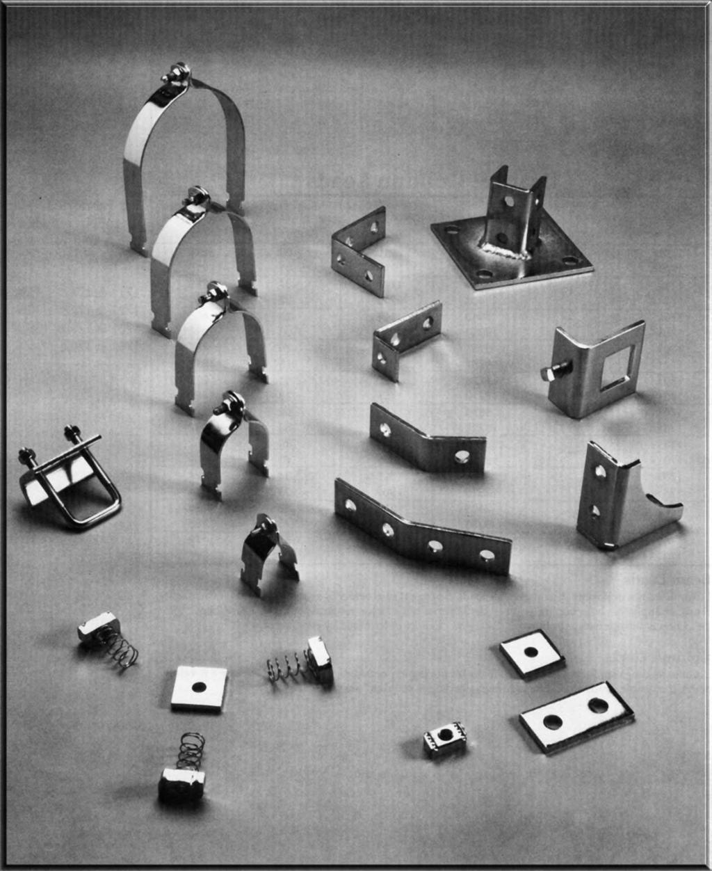
69 Accessories 42
70 Strut Clamps I.P. Pipe Clamp Max. Rec. Fig. Pipe O.D. Std. Material Loads (in Lbs.) Wt. Each Number Size Size Package Size (in Lbs.) X Y Z 200 / Ga / Ga / Ga Ga / Ga / Ga / Ga /2 2 7 / Ga / Ga / Ga /2 25 Ga Ga /8 25 Ga /8 25 Ga /4 25 Ga /4 25 Ga Available in aluminum and stainless steel. Price on request. To order aluminum, add suffix AL to fig. number. To order stainless steel, specify 04 or 6 and add suffix SS to fig. number. Universal Pipe Clamp for EMT, IMC & GRC Fig. Nominal O.D. Size Std. Material Max. Rec. Loads (in Lbs.) Wt. Each Number Size Range Package Size X Y Z (in Lbs.) 20 /8.557 to Ga /2.706 to Ga /4.922 to Ga to Ga /4.50 to Ga /2.740 to Ga to Ga Specify figure number and nominal size Low carbon steel Electro-galvanized Specify figure number and pipe size Low carbon steel Electro-galvanized EMT Conduit Clamp Fig. EMT Std. Material Max. Rec. Loads (in Lbs.) Wt. Each Number Size Package Size X Y Z (in Lbs.) 220 / Ga / Ga / Ga Ga / Ga / Ga Ga Specify figure number and EMT size. Low carbon steel Electro-galvanized 4
71 Strut Clamps Low carbon steel Copper Color Epoxy Finish Specify figure number and tube size APPLICATION: For use with No-Hub Cast Iron Soil Pipe Fig. Number Low carbon steel Electro-galvanized Specify figure number and O.D. tube size. 44 No-Hub Cast Iron Soil Nom. Pipe Size 2006 / Copper Tubing Clamp Max. Rec. Fig. Tube Std. Material Loads (in Lbs.) Wt. Each Number Size Package Size X Y Z (in Lbs.) 20 / Ga / Ga / Ga / Ga Ga / Ga / Ga Ga / Ga Ga / Ga Ga Ga Ga O.D. Tube Clamp Max. Rec. Fig. O.D. Std. Material Loads (in Lbs.) Wt. Each Number Size Package Size X Y Z (in Lbs.) 240 / Ga / Ga / Ga / Ga / Ga / Ga Ga / Ga / Ga / Ga / Ga Ga / Ga / Ga Ga / Ga / Ga / Ga / Ga / Ga Ga / Ga / Ga / Ga /8 50 Ga /4 50 Ga /8 50 Ga /8 50 Ga /4 25 Ga /8 25 Ga /8 25 Ga /4 25 Ga /8 25 Ga Ga /8 25 Ga
72 Strut Clamps O.D. Tube Clamp - Cont d. Max. Rec. Fig. O.D. Std. Material Loads (in Lbs.) Wt. Each Number Size Package Size X Y Z (in Lbs.) /4 25 Ga /8 25 Ga /2 25 Ga /8 25 Ga /4 25 Ga /8 25 Ga Ga /8 25 Ga /4 25 Ga /8 25 Ga /2 25 Ga /4 25 Ga /8 25 Ga Ga /8 25 Ga /4 25 Ga /8 25 Ga /2 25 Ga /8 25 Ga /4 25 Ga /8 25 Ga Ga /8 25 Ga /4 25 Ga /8 25 Ga /2 25 Ga Available in aluminum and stainless steel. Price on request. To order aluminum, add suffix AL to fig. number. To order stainless steel, specify 04 or 6 and add suffix SS to fig. number. Clamp With Cushion Fig. O.D. Size Nom. Tube Std. Wt. Each Number A Size B C D Package (in Lbs.) 250 /4 /8 /6.060 / /8 /4 / / /2 /8 /8.060 / /8 /2 / / /4 5 /8 /4.075 / /8 /4 7 /8.075 / /8 2 /6.075 / /8 /4 2 7 /6.075 / / / /8 2 / / /8 2 /2 7 /8.05 / /8 4 5 /6.05 / /8 4 5 / / suffix SS to fig. number. Price on request Low carbon steel Electro-galvanized Specify figure number and O.D. tube size A B C D Low carbon steel Western gold Specify figure number and O.D. size. EPDM STOCK: Thickness: /8 Length: 25 ft./box Specify figure number and number of feet. Cushion Material 2600 Service Temp: -70 to 50 F Weight per ft:.02 5/8 /6 45
73 Strut Nuts 00-0 Low carbon steel Electro-galvanized Specify figure number and thread size. 0- Low carbon steel Electro-galvanized Specify figure number and thread size Low carbon steel Electro-galvanized Strut Nut without Spring Fig. Thread Std. Weight Each Number Size Package Thickness (in Lbs.) 00 # / # / # / * /4 00 / /6 00 / * /8 00 / /6 00 / * /2 00 / /8 00 /2. 00 /4 00 / /8 00 /2. Available in stainless steel. To order, specify 6 and add *Available in aluminum. To order, add suffix AL to fig. number. Price on request. Strut Nut with Spring Fig. Thread Std. Weight Each Number Size Package Thickness (in Lbs.) 0 # / # / # / * /4 00 / /6 00 / * /8 00 / /6 00 /8.0 08* /2 00 / /8 50 /2.5 0 /4 50 /2.5 7 /8 50 /2.5 Available in stainless steel. To order, specify 6 and add *Available in aluminum. To order, add suffix AL to fig. number. Price on request. Strut Nut with Short Spring Fig. Thread Std. Weight Each Number Size Package Thickness (in Lbs.) 20 # / # / # / /4 00 / /6 00 / /8 00 / /6 00 / /2 00 / /8 50 / /4 50 /8.0 Specify figure number and thread size. 46
74 Strut Nuts Strut Nut with Long Spring Fig. Thread Std. Weight Each Number Size Package Thickness (in Lbs.) 0 # / # / # / /4 00 / /6 00 / /8 00 / /6 00 / /2 00 / /8 50 /2.5 0 /4 50 /2.5 7 /8 50 /2.4 Specify figure number and thread size. Shallow Strut Nut without Spring 0- Low carbon steel Electro-galvanized 5-5 Fig. Thread Std. Weight Each Number Size Package Thickness (in Lbs.) 5 /2 00 / /8 00 /8. 5 /4 00 /8.09 Specify figure number and thread size. Low carbon steel Electro-galvanized Squeeze Nut Fig. Thread Std. Wt. Each Number Size Package (in Lbs.) 404 / / / Specify figure number and thread size. NOTE: Fits all profiles of strut Low carbon steel Electro-galvanized 47
75 Continuous Concrete Insert " X /8" X 2 Gauge " X /6" X 2 Gauge /6 /6 8 8 /8 2 9 /6 /6 2 5 /6 7 /8 Low carbon steel /6 Dia. nail holes Pre-galvanized Available in various lengths. Specify length and figure number. Fig. Length Max. Rec. Wt. Bundle Number (feet) Load/Lbs./ft. Per Foot Qty Note: Furnished with styrofoam filler " X " X 2 Gauge 4 7 /8 /6 Dia. nail holes 4 Low carbon steel Pre-galvanized Available in various lengths. Specify length and figure number. Fig. Length Max. Rec. Wt. Bundle Number (feet) Load/Lbs./ft. Per Foot Qty Note: Furnished with styrofoam filler " X " X 2 Gauge /6 /6 8 8 /8 2 /4 7 /8 4 4 /6 Dia. nail holes Low carbon steel Low carbon steel Pre-galvanized Pre-galvanized Available in various lengths. Specify Available in various lengths. Specify length and figure number. length and figure number. Fig. Length Max. Rec. Wt. Bundle Number (feet) Load/Lbs./ft. Per Foot Qty. Fig. Length Max. Rec. Wt. Bundle Number (feet) Load/Lbs./ft. Per Foot Qty Note: Furnished with styrofoam filler. Note: Furnished with styrofoam filler. 7 /8 48
76 End Caps & Plastic Closures Type A End Caps Fig. Std. Use With Wt. Each Number Package Fig. Numbers (in Lbs.) & & & suffix SS to fig. number. Price on request. Low carbon steel Type B End Caps /8 Fig. Std. Use With Wt. Each Number Package Fig. Numbers (in Lbs.) /4 2 7 /8 Low carbon steel 4500 Plastic Closure Strip Fig. Std. Wt. Per Foot Number Length (feet) (in Lbs.) Plastic Plain 49
77 Flat Plate Fittings Square Washer No Turn Square Washer Fig. Rod Std. Wt. Each Number Size Package (in Lbs.) 5000 / / / / / X Specify figure number and rod size. Fig. Rod Std. Wt. Each Number Size Package (in Lbs.) 5005 / / / / / X Specify figure number and rod size Hole Splice Plate Hole Splice Plate B B C C Fig. Length Std. Wt. Each Number B C Package (in Lbs.) 500 /2 7 / /8 2 / / X Specify figure number and length B. HOLE DIM: 9 /6 dia. /6 from end Fig. Length Std. Wt. Each Number B C Package (in Lbs.) 50 5 /8 7 / / X Specify figure number and length B. HOLE DIM: 9 /6 dia. /6 from end 50
78 Flat Plate Fittings Hole Splice Plate Hole Splice Plate /4 7 /4 / X HOLE DIM: 9 /6 dia. /6 from end 7 /8 on centers HOLE DIM: 9 /6 dia. /6 from end 7 /8 on centers Hole Splice Plate Hole Swivel Plate 9 /8 5 /8 5 / X HOLE DIM: 9 /6 dia. /6 from end 7 /8 on centers X HOLE DIM: 9 /6 dia. /6 from end 5
79 Flat Plate Fittings 502 -Hole Swivel Plate Hole Corner Plate /2 5 /8 7 /8 / X HOLE DIM: 9 /6 dia. /6 from end 7 /8 on centers HOLE DIM: 9 /6 dia. /6 from end 7 /8 on centers Hole Corner Plate Hole Tee Plate /2 5 /8 5 /8 / HOLE DIM: 9 /6 dia. /6 from end 7 /8 on centers HOLE DIM: 9 /6 dia. /6 from end 7 /8 on centers 52
80 Flat Plate Fittings Hole Cross Plate Hole Corner Gusset Plate /2 /2 5 /8 5 / HOLE DIM: 9 /6 dia. /6 from end 7 /8 on centers HOLE DIM: 9 /6 dia. /6 from end 7 /8 on centers Hole Corner Gusset Plate Hole Corner Gusset Plate 5 /8 5 /8 /2 5 / HOLE DIM: 9 /6 dia. /6 from end 7 /8 on centers HOLE DIM: 9 /6 dia. /6 from end 7 /8 on centers 5
81 Flat Plate Fittings Hole Tee Gusset Plate Hole Tee Gusset Plate /2 /2 /2 5 / HOLE DIM: 9 /6 dia. /6 from end 7 /8 on centers HOLE DIM: 9 /6 dia. /6 from end 7 /8 on centers Hole Tee Gusset Plate Hole Tee Gusset Plate 5 /8 9 /8 5 /8 / HOLE DIM: 9 /6 dia. /6 from end 7 /8 on centers HOLE DIM: 9 /6 dia. /6 from end 7 /8 on centers 54
82 Flat Plate Fittings Hole Cross Gusset Plate Hole Cross Gusset Plate 9 /8 5 /8 9 /8 / HOLE DIM: 9 /6 dia. /6 from end 7 /8 on centers HOLE DIM: 9 /6 dia. /6 from end 7 /8 on centers 55
83 90 Fittings Hole Angle 50 2-Hole Corner Angle B 2 /4 X 7 /8 Fig. Length Std. Wt. Each Number B Package (in Lbs.) 50 7 / / / / Specify figure number and length B. HOLE DIM: 9 /6 dia. /6 from end 52 2-Hole Corner Angle X HOLE DIM: 9 /6 dia. /6 from end Hole Corner Angle B 7 /8 2 /6 7 / X HOLE DIM: 9 /6 dia. /6 from end Fig. Length Std. Wt. Each Number B Package (in Lbs.) / X Specify figure number and length B. HOLE DIM: 9 /6 dia. /6 from end 56
84 90 Fittings 59 No-Turn 2-Hole Corner Angle 520 -Hole Corner Angle / / X X HOLE DIM: 9 /6 dia. /6 from end HOLE DIM: 9 /6 dia. /6 from end 7 /8 on centers 52 -Hole Corner Angle 522 -Hole Corner Angle 4 /6 5 /6 7 / X HOLE DIM: 9 /6 dia. /6 from end 7 /8 on centers X HOLE DIM: 9 /6 dia. /6 from end 7 /8 on centers 57
85 90 Fittings 52 -Hole Corner Angle 50 4-Hole Corner Angle /2 /4 2 4 / X HOLE DIM: 9 /6 dia. /6 from end 7 /8 on centers X HOLE DIM: 9 /6 dia. /6 from end 7 /8 on centers 5 4-Hole Corner Angle 55 4-Hole Corner Angle /6 7 /8 2 /4 / X HOLE DIM: 9 /6 dia. /6 from end 7 /8 on centers HOLE DIM: 9 /6 dia. /6 from end on centers 58
86 90 Fittings 540 & 545 -Hole Offset Bent Angle Fig. 540 Right Fig. 545 Left 54 & 546 -Hole Offset Bent Angle Fig. 54 Right Fig. 546 Left 7 /8 /4 7 /8 /2 Right Hand Shown Right Hand Shown 2 /6 2 / HOLE DIM: 9 /6 dia. /6 from end on centers HOLE DIM: 9 /6 dia. /6 from end 7 /8 on centers 548 -Hole Offset Bent Tee Hole Offset Bent Tee 2 5 /8 4 7 /8 2 / HOLE DIM: 9 /6 dia. /6 from end HOLE DIM: 9 /6 dia. /6 from end 7 /8 on centers 59
87 90 Fittings Fig. 555 Right Fig. 556 Left 555 & Hole Offset Bent Tee Hole Offset Bent Tee 2 /6 5 /8 2 /6 /4 Right Hand Shown /2 / HOLE DIM: 9 /6 dia. /6 from end 7 /8 on centers 565 Universal Shelf Bracket HOLE DIM: 9 /6 dia. /6 from end 7 /8 on centers 566 Universal Welded Shelf Bracket 4 /8 4 /8 4 /8 4 /8 7 /8 7 / HOLE DIM: 9 /6 dia. /6 from end /4 on centers HOLE DIM: 9 /6 dia. /6 from end /4 on centers 60
88 90 Fittings 570 & Hole Corner Gusset 57 & Hole Corner Gusset Fig. 570 Right Fig. 575 Left Fig. 57 Right Fig. 576 Left 5 /6 /2 /2 4 /6 Right Hand Shown 7 /8 Right Hand Shown HOLE DIM: 9 /6 dia. /6 from end 7 /8 on centers 580 -Hole Gussetted Shelf Angle HOLE DIM: 9 /6 dia. /6 from end 7 /8 on centers Hole Gussetted Shelf Angle /2 /2 2 5 /6 4 / HOLE DIM: 9 /6 dia. /6 from end 7 /8 on centers HOLE DIM: 9 /6 dia. /6 from end 7 /8 on centers 6
89 90 Fittings Hole Gussetted Shelf Angle Hole Gussetted Shelf Angle 5 /8 5 /8 4 /8 5 / HOLE DIM: 9 /6 dia. /6 from end 7 /8 on centers HOLE DIM: 9 /6 dia. /6 from end 7 /8 on centers Hole Joint Angle Connector Hole Joint Angle Connector /2 /2 /2 /2 2 /4 4 / HOLE DIM: 9 /6 dia. /6 from end 7 /8 on centers HOLE DIM: 9 /6 dia. /6 from end 7 /8 on centers 62
90 90 Fittings Fig. 520 Right Fig. 52 Left 520 & 52 6-Hole Gussetted Corner Connector / Hole Adjustable Corner Angle 2 5 /8 9 /6 4 /6 /2 X 9 /6 Slot 2 5 /8 Right Hand Shown HOLE DIM: 9 /6 dia. /6 from end 7 /8 on centers Hole Adjustable Corner Angle X HOLE DIM: 9 /6 dia. /6 from end Hole Adjustable Corner Angle 2 5 /8 2 /8 9 /6 /2 X 9 /6 Slot 6 7 /8 2 9 /6 X 9 /6 Slot 7 / X HOLE DIM: 9 /6 dia. /6 from end X HOLE DIM: 9 /6 dia. /6 from end 6
91 90 Fittings Hole Adjustable Corner Angle Hole Adjustable Corner Angle 2 /8 /2 2 /4 4 7 /8 /2 /2 2 9 /6 X 9 /6 Slot 2 9 /6 X 9 /6 Slot X HOLE DIM: 9 /6 dia. /6 from end 520 -Hole Adjustable Corner Angle HOLE DIM: 9 /6 dia. /6 from end Hole Adjustable Corner Angle 2 5 /8 /2 X 9 /6 Slots /2 X 9 /6 Slot 7 /8 / /8 7 / X HOLE DIM: 9 /6 dia. /6 from end 7 /8 on centers HOLE DIM: 9 /6 dia. /6 from end 7 /8 on centers 64
92 90 Fittings Hole Adjustable Corner Angle Hole Tapped Corner Angle 5 /6-8 Tapped /2 X 9 /6 Slots 7 /8 /4 8 5 /8 6 7 / HOLE DIM: 9 /6 dia. /6 from end 7 /8 on centers X HOLE DIM: 9 /6 dia. /6 from end Hole Bus Duct Angle /2 7 / X HOLE DIM: 9 /6 dia. 65
93 Angle Fittings /6 B o /4 2-Hole Open Angle Connector Fig. Angle Std. Wt. Each Number B o Package (in Lbs.) 50 7 / / / / / / X Specify figure number and angle B. HOLE DIM: 9 /6 dia. /6 from end Hole Open Angle Connector /2 B o /2 Fig. Angle Std. Wt. Each Number B o Package (in Lbs.) / / / / / / X Specify figure number and angle B. HOLE DIM: 9 /6 dia. /6 from end 7 /8 on centers 66
94 Angle Fittings 2-Hole Closed Angle Connector Fig. Angle Std. Wt. Each Number B o Package (in Lbs.) / / / / B o /4 2 /4 X Specify figure number and angle B. HOLE DIM: 9 /6 dia. /6 from end 4-Hole Closed Angle Connector Fig. Angle Std. Wt. Each Number B o Package (in Lbs.) / / / / B 4 9 o /6 4 9 /6 X Specify figure number and angle B. HOLE DIM: 9 /6 dia. /6 from end 67
95 Braces B X 2-Hole 45 Knee Brace Fig. Length Std. Wt. Each Number B Package (in Lbs.) Bulk Bulk 2.80 Specify figure number and length B. HOLE DIM: 9 /6 dia. /6 from end B /4 2-Hole 45 Tubing Knee Brace Fig. Length Std. Wt. Each Number B Package (in Lbs.) Bulk Bulk Bulk Bulk Bulk Bulk Bulk Bulk 4.0 Specify figure number and length B. HOLE DIM: 9 /6 dia. /6 from end B 2-Hole Straight Tubing Brace Fig. Length Std. Wt. Each Number B Package (in Lbs.) Bulk Bulk Bulk Bulk Bulk Bulk Bulk Bulk Bulk Bulk Bulk 6.70 Specify figure number and length B. HOLE DIM: 9 /6 dia. /6 from end 68
96 U Fittings 550 -Hole U Support Hole U Support /6 5 /2 5 / X HOLE DIM: 9 /6 dia. /6 from end X HOLE DIM: 9 /6 dia. /6 from end Hole U Support Hole U Support 2 7 /6 /4 5 /2 5 / X HOLE DIM: 9 /6 dia. /6 from end X HOLE DIM: 9 /6 dia. /6 from end 69
97 U Fittings Hole U Support 55 -Hole U Support 7 /8 4 7 /8 5 /8 5 / X HOLE DIM: 9 /6 dia. /6 from end X HOLE DIM: 9 /6 dia. /6 from end Hole U Support 9 /6 dia. Hole Hole U Support /4 7 /6 dia. (4) Holes 7 /4 / Ga. HOLE DIM: 9 /6 dia. /6 from end X HOLE DIM: 9 /6 dia. /6 from end 70
98 U Fittings Slotted -Hole U Support 554 Stud Ring Connector 2 /2 2 /2 B /2 X 9 /6 Slots Fig. Length Std. Wt. Each Number B Package (in Lbs.) / / / X HOLE DIM: 9 /6 dia HOLE DIM: 9 /6 dia Stud Ring Connector Stud Ring Connector 2 /2 2 /2 2 /2 2 / HOLE DIM: 9 /6 dia. HOLE DIM: 9 /6 dia. 7
99 Z Fittings Hole Offset Z Support Hole Z Support For #200 Strut 2 /8 /2 /2 / X HOLE DIM: 9 /6 dia. /6 from end X HOLE DIM: 9 /6 dia. /6 from end Hole Z Support For #500 Strut Hole Z Support For #600 Strut /2 /2 /2 2 7 / X HOLE DIM: 9 /6 dia. /6 from end X HOLE DIM: 9 /6 dia. /6 from end 72
100 Z Fittings Hole Z Support For #000 Strut Hole Offset Z Support /4 /2 5 / X HOLE DIM: 9 /6 dia. /6 from end X HOLE DIM: 9 /6 dia. /6 from end Hole Z Support / Hole Z Bus Duct Connection 4 7 /8 /2 /2 B X HOLE DIM: 9 /6 dia. /6 from end Fig. Length Std. Wt. Each Number B Package (in Lbs.) / / / X Specify figure number and length B. HOLE DIM: 9 /6 dia. /6 from end 7
101 Z Fittings 5565 Tapped Z Support Hole Z Support /2 B 5 /6-8 Tapped Hole X HOLE DIM: 9 /6 dia. /6 from end Fig. Length Std. Wt. Each Number B Package (in Lbs.) X Specify figure number and length B. HOLE DIM: 9 /6 dia. /6 from end Hole Sheath Corner Connection 5580 Channel Hanger For #000 Strut /2 /6 9 /2 Dia. Hole / X HOLE DIM: 9 /6 dia. /6 from end Ga. 74
102 Z Fittings 558 Channel Hanger For #200 Strut 5582 Channel Hanger For #500 Strut /6 /6 9 /2 Dia. Hole /6 9 /2 Dia. Hole / Ga Ga. 558 Channel Hanger For #600 Strut 5590 Adjustable Offset Gussetted Z Support /2 5 /2 7 /8 2 9 /6 X 9 /6 Slot /6 7 /8 7 /8 9 /2 Dia. Hole 2 7 / Ga HOLE DIM: 9 /6 dia. /6 from end 75
103 Wing Fittings Fig Right Fig. 560 Left 5600 & 560 -Hole Corner Connector Fig Right Fig Left 5605 & Hole Corner Connector 2 /6 2 /6 Right Hand Shown Right Hand Shown /6 /2 / X HOLE DIM: 9 /6 dia. /6 from end X HOLE DIM: 9 /6 dia. /6 from end Fig. 560 Right Fig. 56 Left 560 & 56 5-Hole Corner Connector Fig. 565 Right Fig. 566 Left 565 & Hole Corner Connector 5 /6 /2 5 /6 /2 Right Hand Shown 5 /8 Right Hand Shown X HOLE DIM: 9 /6 dia. /6 from end 7 /8 on centers X HOLE DIM: 9 /6 dia. /6 from end 7 /8 on centers 76
104 Wing Fittings Hole Double Corner Connector Hole Double Corner Connector 2 /6 5 /6 / HOLE DIM: 9 /6 dia. /6 from end Hole Double Corner Connector / HOLE DIM: 9 /6 dia. /6 from end 7 /8 on centers Hole Double Wing Connector /2 5 /6 2 /6 5 / HOLE DIM: 9 /6 dia. /6 from end 7 /8 on centers 5 7 / HOLE DIM: 9 /6 dia. /6 from end 77
105 Wing Fittings Hole Double Wing Connector Hole Double Wing Connector 5 /6 5 /6 2 5 /2 2 5 /2 5 7 / HOLE DIM: 9 /6 dia. /6 from end 7 /8 on centers Hole Triple Wing Connector 9 / HOLE DIM: 9 /6 dia. /6 from end 7 /8 on centers Hole Triple Wing Connector 2 /6 /4 5 /6 2 5 /2 5 / HOLE DIM: 9 /6 dia. /6 from end 2 5 /2 9 / HOLE DIM: 9 /6 dia. /6 from end 7 /8 on centers 78
106 Wing Fittings Hole Triple Wing Connector Hole Gussetted Double Corner Connector 5 7 /6 5 / / HOLE DIM: 9 /6 dia. /6 from end 7 /8 on centers HOLE DIM: 9 /6 dia. /6 from end 7 /8 on centers Hole Gussetted Double Corner Connector Hole Gussetted Double Corner Connector 9 /6 /2 7 / / HOLE DIM: 9 /6 dia. /6 from end 7 /8 on centers HOLE DIM: 9 /6 dia. /6 from end 7 /8 on centers 79
107 Clevis Fittings Hole U Washer Hole Splice Clevis For #200 Strut Hole Size A /2 /4 Fig. Hole Size Std. Wt. Each Number Size A Package (in Lbs.) 5700 /4 5 / /8 7 / /2 9 / /8 / /4 / gauge HOLE DIM: 9 /6 dia. /6 from end 7 /8 on centers 570 -Hole Splice Clevis For #200 Strut Hole Splice Clevis For #200 Strut 5 /8 7 / HOLE DIM: 9 /6 dia. /6 from end 7 /8 on centers HOLE DIM: 9 /6 dia. /6 from end 7 /8 on centers 80
108 Clevis Fittings Hole Splice Clevis For #000 Strut Hole Splice Clevis For #000 Strut /2 7 / HOLE DIM: 9 /6 dia. /6 from end 7 /8 on centers HOLE DIM: 9 /6 dia. /6 from end 7 /8 on centers Hole Clevis Hole Clevis /6 /2 7 /8 7 /8 B B /6 /6 Fig. Length Std. Wt. Each Number B Package (in Lbs.) / / / Specify figure number and length B. HOLE DIM: 9 /6 dia. /6 from end Fig. Length Std. Wt. Each Number B Package (in Lbs.) Specify figure number and length B. HOLE DIM: 9 /6 dia. /6 from end 8
109 Clevis Fittings Hole Clevis Hole Suspension Clevis 7 /8 7 /6 5 /6 29 /2 2 /2 7 / HOLE DIM: 9 /6 dia. /6 from end X HOLE DIM: 9 /6 dia. /6 from end Hole Suspension Clevis 7 /8 5 /6 2 / X HOLE DIM: 9 /6 dia. /6 from end 82
110 Miscellaneous Fittings 580 & 5802 Single Pipe Axle Support for /4" Pipe 580 & 5804 Single Pipe Axle Support for 2" Pipe Fig. 580 Right Fig Left Fig. 580 Right Fig Left 5 /8 5 /8 Right Hand Shown 5 /8 Right Hand Shown HOLE DIM: 9 /6 dia. /6 from end HOLE DIM: 9 /6 dia. /6 from end 582 Pipe Support Bracket Series Ladder Rungs /2 B X HOLE DIM: 9 /6 dia. /6 from end Fig. Length Std. Wt. Each Number B Package (in Lbs.) bulk 2.4 X Specify figure number and length B. HOLE DIM: 9 /6 dia. /6 from end 8
111 Brackets & Trolleys Wall Ladder Brackets Pipe Coupling Fitting C A B 2 2 /6 5 /8 Fig. Length Std. Wt. Each Number A B C Package (in Lbs.) /8 6 2 / /8 8 4 / / / /8 4 0 /8 bulk.8 X Specify figure number and length B. HOLE DIM: 9 /6 dia. /6 from end Fig. Pipe Std. Wt. Each Number Size Package (in Lbs.) 585 / / X Specify figure number and pipe size. HOLE DIM: 9 /6 dia. /6 from end 5840 Trolley Beam Support 5845 Trolley Beam Joint Support () 9 /6 Dia. Hole 5 /6 () 9 /6 Dia. Hole 5 /6 2 /8 2 /8 (2) 7 /6 Dia. Holes (6) 7 /6 Dia. Holes /2 /2 /2 /2 2 /2 /2 Design Load (in Lbs.) Design Load (in Lbs.)
112 Brackets & Trolleys Stair Support /2 Stair Support 7 /8 7 /8 /6 /6 45 o 7 /2 o /2 /2 8 7 /8 /4 8 7 /8 /4 /2 /2 /6 / X Bearing Trolley Assembly X Bearing Trolley Assembly /2 / Design Load FPM RPM (in Lbs.) Design Load based on use with PHD 000 Series Strut Channel Design Load FPM RPM (in Lbs.) Design Load based on use with PHD 000 Series Strut Channel HOLE DIM: 9 /6 dia. HOLE DIM: 9 /6 dia. 85
113 Post Bases 6005 Post Base for Strut 600 Post Base for Strut (4) Holes /4 Dia. (4) Holes /4 Dia /4 6 4 / HOLE DIM: 9 /6 dia. 605 Post Base for Strut HOLE DIM: 9 /6 dia Post Base for Strut (2) Holes /4 Dia. (4) Holes /4 Dia. /2 6 6 /4 8 / HOLE DIM: 9 /6 dia. HOLE DIM: 9 /6 dia. 86
114 Post Bases 6025 Post Base for Strut 600 Post Base for Strut (4) Holes /4 Dia. /2 (2) Holes /4 Dia. /2 6 4 /4 4 /4 6 6 /4 8 / HOLE DIM: 9 /6 dia. /6 from end 7 /8 on centers 605 Post Base for Double Strut HOLE DIM: 9 /6 dia. /6 from end 7 /8 on centers 6040 Post Base for Double Strut (4) Holes /4 Dia. 6 (4) Holes /4 Dia HOLE DIM: 9 /6 dia. /6 from end 6 4 /4 4 / HOLE DIM: 9 /6 dia. /6 from end 87
115 Post Bases 6045 Post Base for Double Strut 6050 Post Base for Double Strut (2) Holes /4 Dia. (4) Holes /4 Dia. /2 6 6 /4 8 / HOLE DIM: 9 /6 dia. /6 from end 6060 Post Base for Double Strut HOLE DIM: 9 /6 dia. /6 from end 6065 Post Base for Double Strut (4) Holes /4 Dia. (2) Holes /4 Dia. /2 /2 4 /4 6 6 /4 4 /4 6 8 / HOLE DIM: 9 /6 dia. /6 from end HOLE DIM: 9 /6 dia. /6 from end 88
116 Post Bases 6080 Post Base for 5 8 Back to Back Strut 6095 Post Base for 5 8 Strut (4) Holes 7 /6 Dia. /2 /6 /6 5 / HOLE DIM: 9 /6 dia. /6 from end HOLE DIM: 9 /6 dia. 89
117 Brackets /6 C /4 6 /8 B Shelf Bracket Fig. Length Uniform Load Std. Wt. Each Number B C (in Lbs.) Package (in Lbs.) 60 8 / / / Bulk / Bulk 2.95 Note: Load based on use with 2 ga. strut. Specify figure number and length B Single Channel Bracket /6 /6 /4 /6 /4 /4 /4 2 4 /8 602 /4 /4 /8 /4 62 /8 7 /4 /6 C Shelf Bracket B /6 /4 /6 /4 /6 /4 625 Fig. Fig. Length Length Uniform Load Uniform Load Std. Wt. Each Number B B C C (in Lbs.) (in Lbs.) Package (in Lbs.) 62 6 / Bulk / Bulk / Bulk 4.90 Note: Load based on use with 2 ga. strut. Bulk packaging. Specify figure number and length B. 5 /4 / /4 /8 5 /4 7 /4 7 /4 624 /8 7 / Double Channel Bracket /6 2 /8 4 5 /8 B 6 /4 4 5 /8 B Fig. Length Uniform Load Std. Wt. Each Number B (in Lbs.) Package (in Lbs.) Bulk Bulk Bulk 5.09 Note: Load based on use with 2 ga. PHD 000 series strut channel. Specify figure number and length B. HOLE DIM: 9 /6 dia. Fig. Length Uniform Load Std. Wt. Each Number B (in Lbs.) Package (in Lbs.) Bulk Bulk Bulk Bulk Bulk.25 Note: Load based on use with 2 ga. PHD 000 series strut channel. Specify figure number and length B. HOLE DIM: 9 /6 dia. 90
118 Brackets Braced Single Bracket Braced Single Bracket 8 /4 B C B Right Hand Shown Fig. Length Uniform Load Std. Wt. Each Number B (in Lbs.) Package (in Lbs.) Fig. Fig. Length Length Uniform Load Uniform Load Std. Wt. Each Number B B C C (in Lbs.) (in Lbs.) Package (in Lbs.) Bulk /6 225 Bulk Bulk /6 225 Bulk 4.25 PHD 400 Series " profile 2 ga. strut channel used to fabricate this product /6 225 Bulk /6 225 Bulk / /6 275 Bulk /6 275 Bulk 2.04 Specify figure number and length B /6 275 Bulk 2.2 HOLE DIM: 9 /6 dia /6 250 Bulk /6 250 Bulk / / / Note: Load based on use with 2 ga. strut Interlocking Channel Bracket (Slot Up) /2 /4 2 Ga. Specify figure number, R or L and length B B Fig. Length Uniform Load Std. Wt. Each Number B (in Lbs.) Package (in Lbs.) Bulk Bulk 4.50 Note: Load based on use with 2 ga. PHD 000 series strut channel. Specify figure number and length B. HOLE DIM: 9 /6 dia. 9
119 Brackets Interlocking Channel Bracket (Slot Down) 6222 & 6224 Wrap-Around Channel Bracket (Slot Up) /2 /2 B /2 B Fig. Length Uniform Load Std. Wt. Each Number B (in Lbs.) Package (in Lbs.) Bulk Bulk 4.50 Note: Load based on use with 2 ga. PHD 000 series strut channel. Specify figure number and length B. HOLE DIM: 9 /6 dia. 622 & 624 Wrap-Around Channel Bracket (Slot Down) Fig. Length Uniform Load Std. Wt. Each Number B (in Lbs.) Package (in Lbs.) Note: Load based on use with 2 ga. PHD 000 series strut channel. Specify figure number and length B. HOLE DIM: 9 /6 dia & 6248 Wrap-Around Channel Bracket (Slot Up) /2 B 5 /8 B Fig. Length Uniform Load Std. Wt. Each Number B (in Lbs.) Package (in Lbs.) Note: Load based on use with 2 ga. PHD 000 series strut channel. Specify figure number and length B. HOLE DIM: 9 /6 dia. Fig. Length Uniform Load Std. Wt. Each Number B (in Lbs.) Package (in Lbs.) Bulk Bulk 5.0 Note: Load based on use with 2 ga. PHD 000 series strut channel. Specify figure number and length B. HOLE DIM: 9 /6 dia. 92
120 Brackets 605 Single Channel Bracket Support For 00 & 0 Strut 60 Double Channel Bracket Support For 00A & 0A Strut Note: Load is in in.-lbs. and applies to fitting only, not strength of strut arm. Load rating is based on use with 2 gauge strut. If 4 gauge strut is used, load is reduced to 4400 in.-lbs. 5 7 /8 4 /4 Note: Load is in in.-lbs. and applies to fitting only, not strength of strut arm. Load rating is based on use with 2 gauge strut. If 4 gauge strut is used, load is reduced to 900 in.-lbs. 7 /2 4 /4 Fig. Uniform Load Std. Wt. Each Number in. - Lbs. Package (in Lbs.) HOLE DIM: 9 /6 dia. Fig. Uniform Load Std. Wt. Each Number in. - Lbs. Package (in Lbs.) HOLE DIM: 9 /6 dia. Beam Clamps 700 & 7002 Heavy Duty Beam Clamp Continuous Weld Beam Clamp B 5 /8" /4" 2 /2" A Tapped Hole Size Note: Includes Set Screw. Fig. Material Set Max. Rec. Std. Wt. Each Number A Size Screw Load/Lbs. Package (in Lbs.) 700 /8 /6 /2 X /2 /4 /2 X For beams between /4" & " thick flanges Fig. Material Std. Wt. Each Number Size A B C D E Package (in Lbs.) 7005 / /6 / /8-6 5 /6 / /8-6 /2 / C E D A 700 & Low carbon steel Malleable iron 9
121 Beam Clamps 70 & 702 I Beam Clamp 7020 & 7025 I Beam Clamp *Max. load when used in pairs. *Max. load when used in pairs. /6 B /4 " Max. Flange Thickness Fig. Material Set Std. Max. Rec. Wt. Each Number Size Screw Package Load/lbs. (in Lbs.) 70 /4 702 /8 / *.26 / *.64 Note: Includes Set Screw. 9 /6 Hole Furnished on 7025 only C 2 Fig. Std. Max. Rec. Wt. Each Number B C Package Load/lbs. (in Lbs.) / * /2 / *.94 Note: Includes Set Screw. /8 700 Z Beam Clamp *Max. load when used in pairs Beam Clamp *Max. load when used in pairs. 5 /8 /4 " Max. Flange Thickness 27 /2 Fig. Set Std. Max. Rec. Wt. Each Number Screw Package Load/lbs. (in Lbs.) 700 / *.6 Note: Includes Set Screw. Order /2" - X /4 HHCS and Strut Nut Separately /8 Fig. Std. Max. Rec. Wt. Each Number Package Load/lbs. (in Lbs.) *.26 Note: Order /2" - X /4 HHCS and Strut Nut Separately X 94
122 Beam Clamps 2 / & 705 Square U-Bolt /8"-6 Hex Nuts Included 2 / Beam Clamp For use with Strut *Max. load when used in pairs. /8"-6 Threads /2 /4 /4 Fig. Length Std. Wt. Each Number B Package (in Lbs.) Fig. Set Std. Max. Rec. Wt. Each 7050 / Number Screw Package Load/lbs. (in Lbs.) / *.07 /2 Low carbon steel 7070 Beam Clamp For use with Strut 2 /8 *Max. load when used in pairs Beam Clamp For use with /4 Strut 2 /8 *Max. load when used in pairs. /8 5 /8 Dia. Fig. Std. Max. Rec. Wt. Each Number Package Load/Lbs. (in Lbs.) /8 Dia. Fig. Std. Max. Rec. Wt. Each Number Package Load/Lbs. (in Lbs.) * *.88 95
123 Pipe Clamps One Hole Clamp For O.D. Tubing 770 Pipe Stop B /2 7 /6 Fig. Tubing Std. Wt. Each Number O.D. B Package (in Lbs.) 72 /4 / /6 / /8 / /2 / /8 / /4 5 / /8 / / Ga. Specify figure number and O.D. size Standard Pipe Strap Y Z C X B Max. Rec. Fig. Pipe Std. Material Loads (in Lbs.) Wt. Each Number Size B C Package Size X Y Z (in Lbs.) 725 /2 2 7 / /4 /6 725 / /4 / /2 5 / / /2 6 / / /2 7 5 / / / / / / / /6 0 7 /6 0 7 /6 0 7 /6 0 7 /6 0 7 /6 0 7 /6 0 7 /6 5 / / / / / / / / / / / / / Low carbon steel Electro-galvanized Specify figure number and pipe size. Available in stainless steel. To order, specify 04 or 6 and add suffix SS to fig. number. Price on request. 96

124 Pipe Rollers 7400 Separate Rollers Pipe Roller with Axle Fig. For Pipe Std. Wt. Each Number Sizes Package (in Lbs.) 7400 /2 X 8 0 pr Cast Aluminum Rolls w/steel bracket. Fig. For Pipe Std. Wt. Each Number Sizes Package (in Lbs.) Cast Alum. Rolls w/steel bracket and axle. Specify figure number and pipe size Separate Rollers Rollers with Center Roller Fig. For Pipe Std. Wt. Each Number Sizes Package (in Lbs.) sets.97 Cast Aluminum Rolls w/steel bracket. Fig. For Pipe Std. Wt. Each Number Sizes Package (in Lbs.) sets 8.8 Cast Aluminum Rolls w/steel bracket. 97
STANDARD PIPE CLAMP FIG. 520 & 521
 Designed to be used in the suspension of non-insulated pipe lines. Normally used in conjunction with Fig. 35 weldless eye nut, Fig. 50 eye rod or Fig. 55 welded eye rod to allow flexibility at the rod
PHD Manufacturing, Inc.
 4408 Columbiana-Waterford Road Columbiana, Ohio 44408 Phone: (800) 2-276 (0) 482-9256 Fax: (0) 482-276 www.phd-mfg.com Effective April 99 2 Quick Reference This catalog updated on May, 205 For the most
ORDERING: Specify size, figure number, description, nominal pipe size or special O.D. and C-to-C dimension. C - C LOAD lb.
 Fig. 2110 www.pipingtech.com/fig2110 Sway Strut with 4 of Adjustment Engineered spring supports option 1 option 2 ORDERING: Specify size, figure number, description, nominal pipe size or special O.D. and
TG/RB/2M/Web Rev.12/1/16. Pipe Hangers & Devices
 TG/RB/2M/Web Rev.12/1/16 Pipe Hangers & Devices Pipe Welcome Hangers to PHD & Devices Manufacturing PHD Manufacturing, Inc. was founded in 1972 by a group of industry veterans with strong management, financial,
Pipe Hangers. 47 B-Line series Pipe Hangers & Supports
 Pipe hangers offered in this section are designed to support insulated or non-insulated pipe allowing for vertical adjustment and limited movement in the piping system. Materials arbon Steel, Malleable
SECTION PIPE HANGERS AND SUPPORTS
 Part I - GENERAL 1.01 SECTION INCLUDES A. The work covered under this section consists of the furnishing of all necessary labor, supervision, materials, equipment, and services to completely execute the
229 B-Line series Pipe Hangers & Supports
 accessories offered in this section are designed to reduce installation time. wide range of types and sizes are available for various applications. Materials For maximum loading design, Carbon Steel, Forged
Pipe Hangers. Pipe Hangers. Pipe Hangers & Supports
 Pipe hangers offered in this section are designed to support insulated or non-insulated pipe allowing for vertical adjustment and limited movement in the piping system. Materials arbon Steel, Malleable
Product Specifications PIPE SUPPORT PRODUCTS
 Product Specifications PIPE SUPPORT PRODUCTS For the most up to date information visit our website: www.taylorassociates.com 1 PICTORIAL INDEX FIG. 41 Page 8 FIG. 41 PVC Page 9 Fig. 42 Page 10 FIG. 43
Product Specifications PIPE SUPPORT PRODUCTS. For the most up to date information visit our website:
 Product Specifications PIPE SUPPORT PRODUCTS For the most up to date information visit our website: www.taylorpipesupports.ca PICTORIAL INDEX FIG. 41 Page 1 FIG. 41 PVC Page 2 FIG. 43 Page 3 FIG. E31 Page
Pipe hanger solutions
 Product catalog Middle East offering Pipe hanger solutions for commercial and industrial applications B00 series B00 - Standard clevis hanger Pipe will not pinch when installing. 5 swing in either direction
CCTF LOOKING BACK AND BEYOND
 CCTF LOOKING BACK AND BEYOND CCTF was incorporated in Canada in 1952 as Clyde Tube Forging, a manufacturer of butt weld fittings originally from Scotland. EMCO Limited purchased the company in 1954. The
SURGE RESTRAINT FIG. 055
 NFPA SWIVL RING HANGR Function: esigned for the suspension of non-insulated stationary pipe lines. The knurled insert nut that allows a vertical adjustment after installation, is tapped to NFPA reduced
CLEVIS HANGER 401. Standard Duty B A
 CLEVIS HNGER 40 Standard Duty Size Range: /2 through 24 Surface Finish: Electro-zinc plated non-insulated pipe lines Standard electro-zinc plated finish is cleaner, provides superior corrosion protection
Introduction. We stay ahead of today s evolving market requirements by committing to a program of continued research and development.
 Pipes & Fittings SHIELD Introduction SHIELD is a company created to cater to the infrastructure, fire protection and building services industries with a comprehensive range of products designed to be competitive
SECTION COMMON WORK RESULTS FOR FIRE SUPPRESSION. A. Pipe, fittings, valves, and connections for sprinkler systems.
 SECTION 210500 - COMMON WORK RESULTS FOR FIRE SUPPRESSION PART 1 GENERAL 1.1 SECTION INCLUDES A. Pipe, fittings, valves, and connections for sprinkler systems. 1.2 RELATED REQUIREMENTS A. Section 099000
Utilities Catalog. PC-U2008, February, 2008
 Utilities Catalog PC-U2008, February, 2008 Tyler Utilities 11910 CR. 492 Tyler, Texas 75706 (800) 527-8478 Union Foundry Company Box 309 Anniston, Alabama 3602 (800) 226-7601 TABLE OF CONTENTS Item Page
Pipe Hangers, Strut & Accessories
 I N D U S T R I E S I N C. Base Price List September 22, 2008 Pipe Hangers, Strut & Accessories Phone 800.243.4844 860.647.1431 Fax 860.647.1160 180 Olcott Street Manchester, CT 06040 w w w. e m p i r
Beam Clamps. Materials & Finishes (Unless otherwise
 Beam Clamps Our beam attachments and pipe supports offered in this section are designed to provide supports without drilling or welding. complete selection of beam clamps, pipe clamps, rollers, supports
Pipe/Conduit Clamps & Hangers
 Our beam attachments and pipe supports offered in this section are designed to provide supports without drilling or welding. complete selection of beam clamps, pipe clamps, rollers, supports and accessories
INTRODUCTION SAKETH EXIM
 Certificates INTRODUCTION SAKETH EXIM is an Industrial Powerhouse with a dominant presence in Manufacturing and Fabrication of Metal Products used in Pipe Support Systems, HVAC Anti Vibration System and
Pipe Brackets - Pipe Support. Systems Brass Pipe brackets Brass Pipe clips
 Select Language Home Profile Products Contact Us Email Resources Brass Sanitary Fittings Brass Cable Glands Cable Gland Accessories Brass Fasteners Pipe Brackets - Pipe Support Systems Brass Pipe brackets
Fig Fig. 290L: Left-Hand Thread. rod attachments. Extension piece
 ig. xtension piece Range: " through " Material: Malleable iron Maximum Temperature: 40 Service: or attaching hanger rod to various types of building attachments. pprovals: UL Listed ( " - " rod size) and
TABLE OF CONTENTS. Pipe Diameter Chart (Reference Only)..50 Extensions 38,40,42,44
..50 Extensions 38,40,42,44") TABLE OF CONTENTS Item Page Item Page ANSI/AWWA Compact & Full Body Pipe Fittings: Product Submittals and Installation: Mechanical & Flange Joint C153. 3-9 20U Protective Fusion Bonded Epoxy....5,5 Mechanical
TABLE OF CONTENTS Item Page Item Page ANSI/AWWA Compact & Full Body Pipe Fittings: Product Submittals and Installation: Mechanical & Flange Joint C153. 3-9 20U Protective Fusion Bonded Epoxy....5,5 Mechanical
A. American National Standards Institute: 1. ANSI Z Relief Valves for Hot Water Supply Systems.
 SECTION 220523 - PLUMBING VALVES PART 1 - GENERAL 1.1 SUMMARY A. Section Includes: 1. Ball valves. 2. Butterfly valves. 3. Swing check valves. 4. Spring loaded check valves. 5. Water pressure reducing
Ford Fabricated Steel Products
 Ford Fabricated Steel Products Section N2 12/2000 The Ford Meter Box Co., Inc. 775 Manchester Avenue, P.O. Box 443, Wabash, Indiana, USA 46992-0443 Telephone: 219/563-3171 FAX: 1-800-826-3487 Overseas
PVC Stargrip series 4000 Mechanical Joint Wedge Action Restraint for Plastic Pressure Pipe
 Joint Restraint Products PVC Stargrip series 4000 Mechanical Joint Wedge Action Restraint for Plastic Pressure Pipe INFORMATION The PVC Stargrip Mechanical Joint Restraint System is a unique product with
PIPE SUPPORT HARDWARE
 atalog No. 6. WITH PIPE SUPPORT SYSTEMS PIPE SUPPORT HRDWRE RPENTER & PTERSON, IN. DESIGNERS ENGINEERS MNUFTURERS Introduction Since 9 arpenter & Paterson, Inc. has specialized in the manufacture and distribution
PVC Stargrip series 4000 Mechanical Joint Wedge Action Restraint for Plastic Pressure Pipe
 PVC Stargrip series 4000 Mechanical Joint Wedge Action Restraint for Plastic Pressure Pipe INFORMATION The PVC Stargrip Mechanical Joint Restraint System is an exceptional restraint system for mechanical
Steel Fabricated Coupling
 Steel Fabricated Coupling Straight Connection IMPORTANT LINKS Click appropriate words to go to: Standard Limited Warranty Sales Terms & Conditions Freight Policy Returns Policy Corrosion & Product Selection
SECTION GENERAL-DUTY VALVES FOR HVAC. A. Section includes valves for building services piping.
 SECTION 23 05 23 GENERAL-DUTY VALVES FOR HVAC PART 1 - GENERAL 1.1 SUMMARY A. Section includes valves for building services piping. 1.2 REFERENCES A. AGA Z21.22 (American Gas Association) - Relief Valves
Ford Service Saddles and Tapping Sleeves
 DQS Inc. Section AA 09/2017 THE FORD METER BOX COMPANY, INC. CERTIFIED TO ISO 9001:2015 10004466 Ford Service Saddles and Tapping Sleeves Contents Recommended Product Application *Steel *C900/909*** Cast
Pipe Size Pipe OD TwinSeal Hinged Design for IPS PVC Pipe MODEL 3402 BRONZE SADDLE FOR COPPER TUBING
 MULTIPLIER SERVICE SADDLES MODEL 3401 BRONZE SADDLE FOR IPS PVC BODY CASTINGS: Waterworks Bronze (85-5-5-5) per ASTM B584 and AWWA C800. FASTENERS: Silicon Bronze per ASTM B98. GASKET: Patented SBR TwinSeal
FIG Gruvlok Flange Adapter
 FIG. 88 Gruvlok Adapter The Gruvlok Fig. 88 Adapter allows for direct connection of Class 125 or Class 150 flanged components to a grooved piping system. The Gruvlok Adapter provides an alternative method
CAST IRON FITTINGS STANDARD
 060-1 CAST IRON FITTINGS STANDARD ITEM 1/4" 3/8" 1/2" 3/4" 1" 1-1/4" 1-1/2" 2" 90 ELL 11.03 15.95 6.99 7.29 8.62 12.24 16.93 26.45 90 REDUCING ELL * 22.20 14.69 12.27 15.44 31.19 41.74 45 ELL 13.59 14.60
Ford Service Saddles and Tapping Sleeves
 Section AA 04/2013; web revision 02/2014 Ford Service Saddles and Tapping Sleeves The Ford Meter Box Company, Inc. 775 Manchester Avenue, P.O. Box 443, Wabash, Indiana, USA 46992-0443 Telephone: 260-563-3171
Superstrut. Metal Framing. Threaded Products and Hardware. Channel Nuts. Design Data. Screw Threads. Finish and special materials
 Channel Nuts Superstrut channel nuts are manufactured from Grade 2 mild steel and are case hardened. Design Data Superstrut self aligning channel nuts are designed to provide resistance to pullout and
STANDARD PRODUCTS CATALOG
 STANDARD PRODUCTS CATALOG 1 NO. 1 SUMMER 01 We are not limited to the enclosed items. We have the ability to custom fabricate products to meet your needs. A few of the items we also fabricate are: Pipe
PART NUMBER POLE DIAMETER RANGE CARTON QTY " to 5" " to 6 3 4" " to 7 3 4" " to 8 3 4" 10
 PH1 Offset Pole Band Bands Single Double Offset Pole Bands are used for dead-ending, guying, and mounting secondary racks on metal poles, pipe masts, or conduit. Each Pole Band Assembly contains two 1
Reference Data. Schedule 40 Steel Pipe Data. Schedule 80 Steel Pipe Data
 Schedule 40 Steel Pipe Data Maximum Recommended Pipe Size Pipe O.D. Thickness Weight of Pipe Filled With Water Span* Hanger Rod Ft. Meter Sizes 3/8" (10).675 (17.1).091 (2.3).6 (.9).7 (1.0) 7 (2.13) 3/8"-16
SECTION SWING CHECK VALVES
 PART 1 GENERAL 1.1 DESCRIPTION This section includes materials, testing, and installation of swing check valves as shown in the Drawings and specified herein, in accordance with the requirements of the
Section 8 AMERICAN. Flanged Pipe
 Section 8 AMERICAN Flanged Pipe The principal standards covering Flanged Pipe are ANSI/AWWA C115/A21.15 and ANSI/AWWA C110/A21.10. These and other standards are referenced throughout this Section either
TYLER UNION. Quality Waterworks Products. PC-2017, March, REGISTERED FIRMISO 9001:2015. Tyler Union
 TYLER UNION Quality Waterworks Products WATERWORKS CATALOG PC-2017, March, 2017 www.tylerunion.com 10014257 U L REGISTERED FIRMISO 9001:2015 CERTIFIED Tyler Union 11910 CR 492 TYLER, TEXAS 75706 (800)
The Number One Choice of Line Stopping Contractors
 JCM 0 Line Stop Fittings Take a Look!!! JCM 0 FAMILY OF LINE STOP FITTINGS HAS EPANDED New Plug Option - New Numbering System Whatever your application needs, JCM has it! JCM Industries offers the largest
Section N. 09/2017 Web Revision 10/23/2017 THE FORD METER BOX COMPANY, INC. CERTIFIED TO ISO 9001: Ford Fabricated Steel Products
 DQS Inc. THE FORD METER BOX COMPANY, INC. CERTIFIED TO ISO 9001:2015 10004466 Section N 09/2017 Web Revision 10/23/2017 Ford Fabricated Steel Products Contents Page Product Numbering System... 3 Information...............................................................
TOTAL PIPING SOLUTIONS, INC. TRIPLE-TAP
 TOTAL PIPING SOLUTIONS, INC. TRIPLE-TAP Extended Range Stainless Steel Push Plug Line Stop Tapping Sleeve Technical Specifications Controlled Document: ENGTS-05/120417 December 2017 TRIPLE TAP Extended
FITTINGS AND FABRICATIONS DESIGNED AND ENGINEERED HIGH DENSITY POLYETHYLENE PIPE
 Effective May 24, 2002 Cancels all previous publications U.S. Price $12.95 FITTINGS AND FABRICATIONS DESIGNED AND ENGINEERED FOR HIGH DENSITY POLYETHYLENE PIPE JCM Industries, Inc. P.O. Box 1220 Nash,
Pipe Support Systems & Components. EDITION 3.
 Pipe Support Systems & Components 10 899 4 sales@anchoragegroup.com.au www.anchoragegroup.com.au ABOUT ANCHORAGE GROUP ABOUT ANCHORAGE Leading manufacturing company Swift Metal Services designs, manufactures
TEL: Version: KW2
 WWW.KLAMBON.COM 1 Page Klambon Water is a wholly owned subsidiary of West Rand Engineering (WRE), we are suppliers of valves, fittings and related products to all industries and our service extends to
YOUR FULL LINE SOURCE FOR PVC ELECTRICAL PRODUCT
 CANTEX INC. 301 Commerce Ste 2700 Fort Worth, Texas 76102 817-215-7000 Fax: 817-215-7001 Conduit Fittings & Accessories Directional Drilling Conduit Utility Duct Telephone Duct Residential Boxes YOUR FULL
General Cable Support Information
 General Cable Support Information Applications Used to support cables in vertical raceways or risers. Relieves the strain that would be placed on terminations, the interior of panels, or other devices
Grooved End Fittings. System No. Submitted By Spec Sect Para Location Date Approved Date CARBON STEEL PIPE - GROOVED FITTINGS
 SEE VICTAULIC PUBLICATION 10.01 FOR DETAILS Victaulic offers a broad line of fittings in sizes through 48 /1200 in a variety of straight and reducing styles. Most standard fittings are cast of durable
Champion Series Zero-Turn Riders & Mower Decks
 Parts Manual Champion Series Zero-Turn Riders & Mower Decks HP Tractors Mfg. No. Description Champion, HP Zero-Turn Rider Champion, HP Zero-Turn Rider (CE) 0HP Tractors Mfg. No. Description Champion, 0HP
Super Flange series 7200 Designed for use on Ductile Iron, Steel, PVC, PVCO and HDPE Pipes
 Designed for use on Ductile Iron, Steel, PVC, PVCO and HDPE Pipes INFORMATION The Series 7200 Super Flange is a restrained flange adapter designed to connect plain end pipe to a flange end component. May
B U I L D I N G C O N N E C T I O N S T H AT L A S T
 B U I L D I N G C O N N E C T I O N S T H AT L A S T pipe to pipe and people to people. We pride ourselves in providing the finest-quality pipe products and services with integrity and dedication to superior
***************************************************************************************************************
 15515 VALVES, HANGERS, AND SPECIALTIES *************************************************************************************************************** SPECIFIER: CSI MasterFormat 2004 number:23 21 16 ***************************************************************************************************************
See our expanding selection of products on Product Portfolio
 See our expanding selection of products on www.fnw.com Product Portfolio Table of Contents Low Lead Products- Page 3 Ball Valves, Check Valves, Strainers, Water Hammer Arrestors Ball Valves, Brass - Page
We Make Good Neighbors!
 2 We Make Good Neighbors! 3 1 6 11 2 7 12 3 8 13 4 9 14 5 10 15 4 11 1/2 GAUGE x 2 3/8 MESH 3 High 50035 4 High 50045 5 High 50050 6 High 50055 9 GAUGE X 2 MESH Knuckle Twist 0.148 GAW - ASTM A 392, Class
Electrical Applications. Metal Framing & Cable Tray Superstrut Metal Framing System. Column A. Design Data: Materials: Column B
 Electrical Raceway Series 800 Surface Raceway and Lighting Systems Superstrut channel together with snap-in closure strip is listed by Underwriters Laboratories as a surface metal raceway. Other accessories
PIPE/CONDUIT CLAMPS, SUPPORTS AND HANGERS FOR 1 5 8" (41 MM) WIDTH SERIES CHANNEL
 WIDTH SERIES CHANNEL") PIPE/CONDUIT CLMPS, SUPPORTS ND HNGERS FOR 5 8" (4 MM) WIDTH SERIES CHNNEL Page Pipe/Conduit Clamps Pipe Hangers Pipe Rollers Pipe Brackets Reference Tables 2 40 4 44 MTERIL Unistrut pipe supports, unless
PIPE/CONDUIT CLMPS, SUPPORTS ND HNGERS FOR 5 8" (4 MM) WIDTH SERIES CHNNEL Page Pipe/Conduit Clamps Pipe Hangers Pipe Rollers Pipe Brackets Reference Tables 2 40 4 44 MTERIL Unistrut pipe supports, unless
UNION-TITE DUCTILE IRON C153 COMPACT FITTINGS
 Sizes 4"-12" UL Listed for Fire Main Equipment SAMPLE SPECIFICATIONS (Current ANSI/AWWA revisions apply) 4" through 24" Push-On joint ductile iron fittings shall be produced in accordance with all applicable
Conduit Fittings & Accessories Directional Drilling Conduit Utility Duct Telephone Duct Residential Boxes
 CANTEX INC. 301 Commerce Ste 2700 Fort Worth, Texas 76102 817-215-7000 Fax: 817-215-7001 Conduit Fittings & Accessories Directional Drilling Conduit Utility Duct Telephone Duct Residential Boxes YOUR FULL
516509_tabs 11/16/10 4:55 AM Page 1 FIRE HYDRANTS
 Date Printed: November 2010 FIRE HYDRANTS or Tyton (6"),6, or 8" A EDDY FIRE HYDRANTS PARTS LIST WORKING PRESSURE: 150 PSI Note: Discontinued For Reference Only 350 PSI Working Pressure
CHAIN & HOOKS. Proof Coil Chain Grade 28. Transport Chain Grade 70
 Proof Coil Chain Grade 28 Proof coil chain is suitable for use as towing chain, logging,fencing, trailer safety chain, boat anchors, security barriers or other general purposes where chain of high tensile
SPECIFICATIONS SEWAGE/SUMP DUPLEX SYSTEM ZOELLER COMPANY SUBMERSIBLE SEWAGE OR DEWATERING PUMPS
 Product information presented here reflects conditions at time of publication. Consult factory regarding discrepancies or inconsistencies. MAIL TO: P.O. BOX 16347 Louisville, KY 40256-0347 SHIP TO: 3649
' ' ' ' LISTED Elbows Tees Crosses Wyes Reducers Flanges Converters Gaskets Nuts&Bolts
 .., I.,.,... I I...... I I ',,,, ", Elbows Tees Crosses Wyes Reducers Flanges Converters Gaskets Nuts&Bolts ' ; i ',,.) I ' ' ' ' AWWA C Class 50 (3"' ANSI B. Class 5 ("' ANSI B. Class 50 (3"' c@us LISTED
Model R. q Fig. 81-H: Standard Type: q A, q B, q C, q D, q E, q F. q Fig. C-81-H: Corrosion Resistant CONSTANT SUPPORTS.
 OSA SUPPORS odel R q Fig. 81-: Standard : q A, q, q, q, q, q F q Fig. -81-: orrosion Resistant : q A, q, q, q, q, q F onstant Support Finish: Standard finish; painted with semi gloss primer. orrosion resistant;
TECHNICAL SPECIFICATIONS OF METROPOLITAN WATERWORKS AUTHORITY OF THAILAND
 TECHNICAL SPECIFICATIONS OF METROPOLITAN WATERWORKS AUTHORITY OF THAILAND UNDERGROUND STEEL PIPE 1. Inside lining shall be cement mortar in accordance with AWWA C205 for pipe diameters 150-700 mm. OR liquid
SAE FLANGES V C. Specialists in VESCOR. Hydraulic Reservoirs and Accessories
 SAE FLANGES V C VESCOR Specialists in Hydraulic Reservoirs and Accessories V C TABLE OF CONTENTS V C General Information / Split Flange Clamp............................page 1 Welding Information / Simplified
Pipe hangers & ss floor drains
 Pipe support systems, Pipe hangers & ss floor drains profile Sprinkler hanger ABOUT US: With over two decades of experience Aqua Arab Trading Co is a leading exporter and reseller of Hardware solutions
Ground Wire Size. 1/2 in /4 in. 2 in /2 in. 3-1/2 in TB. 4 in. 5 in. #4 4/0 AWG 3906-TB
 lamps Waterpipe Ground lamps Waterpipe Ground lamps Waterpipe Ground lamps 2-T Ground Wire Size Water Pipe Size 1/2 in., 3/4 in., 1 or rebar 4-10 3-T 1-1/4 in., 1-1/2 in. or 2 in. #6, #4, #2 WG 4 2-1/2
Style 234 Restrained Flexible Single-Gasket Coupling. System No. Submitted By Spec Sect Para Location Date Approved Date
 Victaulic Bolted Split-Sleeve Products (VBSP) Style 234 carbon steel couplings (formerly Depend-O-Lok Air/FluidMaster) are single-arch couplings that are commonly used in buried or exposed steel pipe applications
RT / RTE Rear Suspension
 RT / RTE Rear Suspension LIT NO: SP-168 DATE: January 2017 REVISION: F CONTENTS DESCRIPTION Parts Lists Page RT/RTE 34K 40K 46K.... 2 RT/RTE 48K 52K.... 4 RT 65K 70K Heavy-duty... 6 DESCRIPTION Selection
Grooved End Fittings. System No. Submitted By Spec Sect Para Location Date Approved Date CARBON STEEL PIPE - GROOVED FITTINGS
 SEE VICTAULIC PUBLICATION 10.01 FOR DETAILS Victaulic offers a broad line of fittings in sizes through 60"/1500 in a variety of straight and reducing styles. Most standard fittings are cast of durable
P R O D U C T C A T A L O G
 A A A T E C H N O L O G Y & SPECIALTIES CO., INC. P R O D U C T C A T A L O G 2017 Feb. 2 www.aaatech.com P R O U D L Y S E R V I N G I N D U S T R Y S I N C E 1 9 7 1 AAA Technology & Specialties Co.,
Steel Conduits Conduit Fittings Flexible Conduits
 Conduits Conduit Fittings Flexible Conduits CONTENT 1. INTRODUCTION VOLTECX products introduction and selecting VOLTECX 2. STEEL CONDUITS VOLTECX BS4568: Part 1: 1970 (Class 4) Conduit IEC 61386-21:2004;
INDUSTRIAL PIPE SUPPORTS CATALOGUE
 INDUSTRIAL PIPE SUPPORTS CATALOGUE DATE PUBLISHED: 1/06/2017 BINDER GROUP INDUSTRIAL PIPE SUPPORT CATALOGUE TABLE OF CONTENTS 1. INTRODUCTION... 4 2. QUALITY MANAGEMENT CERTIFICATE... 5 3. PIPE SUPPORT
PROJECT TITLE PROJECT NO: CONTRACT TITLE GRANT NO: UNIVERSITY OF CALIFORNIA, DAVIS CITY, CALIFORNIA
 The following standard specification is intended to be edited according to the specifics of the project. Brackets [ ] and areas shaded in gray [e.g. format] indicate requirements that are optional depending
Pipe support systems & Pipe hangers. Stamp of Quality
 Pipe support systems & Pipe hangers Stamp of Quality contents Introduction 4 Clevis Hanger 6 Sprinkler Hanger 8 Split Clamp with EPDM Lining 10 Plain Split Clamp 12 Split Clamp 14 Clevis Hanger 16 Clevis
PIPE CONNECTORS & ACCESSORIES
 PIPE CONNECTORS & ACCESSORIES FLEXIBLE COUPLINGS Transitions cast iron or plastic to cast iron or plastic pipe. 300 series stainless steel clamps Complies with: ASTM C1173-2002 CSA B602-2005 IAPMO 4933
GENERAL-SERVICE COMPRESSED-AIR PIPING SECTION GENERAL-SERVICE COMPRESSED-AIR PIPING PART 1 - GENERAL
 13686.00 GENERAL-SERVICE COMPRESSED-AIR PIPING 221513-1 SECTION 22 1513 - GENERAL-SERVICE COMPRESSED-AIR PIPING 1.1 RELATED DOCUMENTS PART 1 - GENERAL A. Drawings and general provisions of the Contract,
A1062 & A1072 AUGER ASSEMBLY MANUAL. Read & understand all instructions pertaining to this auger prior to use!
 A1062 & A1072 AUGER ASSEMBLY MANUAL Read & understand all instructions pertaining to this auger prior to use! Safety Alert Watch for this ALERT Symbol. It identifies potential hazards to Personal SAFETY
Ford Bolted Flex Couplings. Section M. 5/2008; Web Revision 10/2010
 Section M 5/2008; Web Revision 10/2010 Ford Bolted Flex Couplings The Ford Meter Box Company, Inc. 775 Manchester Avenue, P.O. Box 443, Wabash, Indiana, USA 46992-0443 Telephone: 260-563-3171 FAX: 800-826-3487
Mueller Super Centurion 250 Fire Hydrant
 Mueller Super Centurion 250 Fire Hydrant Designed for efficient flow and outstanding, long-term reliability Mueller Super Centurion 250 Fire Hydrant...250 psig rating, high flow, dependable performance,
Model CV-1FR Grooved-End Riser Check Valves 2 Inch to 12 Inch (DN50 to DN300) General Description. Installation. Technical Data
 General Description. Installation. Technical Data") Worldwide Contacts www.tyco-fire.com Model CV-FR Grooved-End Riser Check Valves Inch to Inch (DN0 to DN00) General Description The TYCO Model CV-FR Grooved- End Riser Check Valve is a compact and rugged
Worldwide Contacts www.tyco-fire.com Model CV-FR Grooved-End Riser Check Valves Inch to Inch (DN0 to DN00) General Description The TYCO Model CV-FR Grooved- End Riser Check Valve is a compact and rugged
Grooved End Fittings. System No. Submitted By Spec Sect Para Location Date Approved Date CARBON STEEL PIPE - GROOVED FITTINGS
 SEE VICTAULIC PUBLICATION 10.01 FOR DETAILS Victaulic offers a broad line of fittings in sizes through 60"/1500 in a variety of straight and reducing styles. Most standard fittings are cast of durable
Ancillary Equipment FIG. 222 FIG. 283 FIG /10 ADJUSTABLE PIPE SUPPORT U BOLT (NON GRIPPED) U BOLT (GRIPPED) Material - Carbon Steel.
 U BOLT (GRIPPED) Material - Carbon Steel.") 78 FIG. 222 FIG. 283 FIG. 1 04/ U BOLT (GRIPPED) Nom A C D T L Load 15 21.3 7 28 6 25 37 220 20 26.9 33 6 25 40 220 25 33.7 40 6 25 43 220 32 42.4 53 35 49 545 40 48.3 16 60 35 56 545 50 60.3 16 71 35
78 FIG. 222 FIG. 283 FIG. 1 04/ U BOLT (GRIPPED) Nom A C D T L Load 15 21.3 7 28 6 25 37 220 20 26.9 33 6 25 40 220 25 33.7 40 6 25 43 220 32 42.4 53 35 49 545 40 48.3 16 60 35 56 545 50 60.3 16 71 35
SECTION AXIAL HVAC FANS
 SECTION 233413 - AXIAL HVAC FANS 1. PART 1 GENERAL 1.1. RELATED DOCUMENTS A. Drawings and general provisions of the Contract, including General and Supplementary Conditions and Division 01 Specification
Note: Proper mixing can be visually ascertained when the epoxy mixture is evenly gray. Part Number Temperature Range Approximate Curing Time
 CHAMPION MIX (Epoxy Adhesive) The CHAMPION MIX system is a two part adhesive, epoxy resin system, designed to permanently bond fittings and joints of fiberglass reinforced epoxy conduit. It is also designed
ADMIRAL HYDRANT. clowvalve.com
 clowvalve.com ADMIRAL HYDRANT AWWA C502 UL LISTED FM APPROVED NSF 61/372 CERTIFIED 250 PSI WORKING PRESSURE 350 PSI WORKING PRESSURE AVAILABLE 10-YEAR LIMITED WARRANTY Clow Valve, A Division of McWane,
HP-SERIES HIGH PERFORMANCE BUTTERFLY VALVES
 BFV-2 HP-SERIES HIGH PERFORMANCE BUTTERFLY VALVES Rev. 09/09 HP-SERIES HIGH PERFORMANCE BUTTERFLY VALVES Now you can turn high pressure applications into low risk decisions by turning to high performance
Ford Brass Saddles Style 101B and 202B
 101B Ford Brass Saddles 101B and 202B 101B, 3/4" and 1" Taps 202B, 3/4" through 2" Taps Specifications Body - 85-5-5-5 brass alloy as per ASTM B62, ASTM B584 and AW WA C800. Threads may be FIP, AW WA,
FIG Gruvlok Flanges
 Gruvlok Flanges The Gruvlok Fig. 7012 Flange allows direct connection of Class 125 or Class 150 flanged components to a grooved piping system. The two interlocking halves of the 2" thru 12" sizes of the
Rigid Metal Conduit, IMC or EMT K-Clamps
 65178 Rigid Metal Conduit, IMC or EMT K-Clamps Wt. Lbs. Std. Catalog No. Size (In.) Per 100 Pkg. Right Angle Type Right Angle Type Hot Dip/Mechanically Galvanized* For Rigid, IMC, EMT PC-50RA 1/2 37.0
COMMERCIAL PRO ILLUSTRATED PARTS MANUAL. Patented
 COMMERCIAL PRO with Patented Models: Z21554CPHO Z21554CPHO-CA Z21560CPHO Z21560CPHO-CA Z2460CPKA Z2460CPKA-CA Z2466CPKA Z2466CPKA-CA Z2460CPKA Shown SWISHER ACQUISITION INC. 1602 CORPORATE DRIVE, WARRENSBURG
Grooved End Fittings. System No. Submitted By Spec Sect Para Location Date Approved Date CARBON STEEL PIPE - GROOVED FITTINGS
 SEE VICTAULIC PUBLICATION 10.01 FOR DETAILS Victaulic offers a broad line of fittings in sizes through 60"/1500 in a variety of straight and reducing styles. Most standard fittings are cast of durable
Mechanical Piping.
 Mechanical Piping www.anvilintl.com JULY 2016 For the most current product/pricing information on Anvil products, please visit our website at www.anvilintl.com BUILDING CNNECINS HA LAS For over 160 years,
COMMERCIAL PRO ILLUSTRATED PARTS MANUAL. Patented
 COMMERCIAL PRO with Patented Models: Z21554CPHO Z21554CPHO-CA Z21560CPHO Z21560CPHO-CA Z2460CPKA Z2460CPKA-CA Z2466CPKA Z2466CPKA-CA Z2460CPKA Shown SWISHER ACQUISITION INC. 1602 CORPORATE DRIVE, WARRENSBURG
Cable Supports. Requirements for Cable Supports in the National Electrical Code reads as follows:
 QA1 General Information are used to support cables in vertical raceways or risers. Cable supports relieve the strain that would be placed on terminations, the interior of panels, or other devices to which
ALL PLANT & MIN TILL DRILL
 4000 SERIES ALL PLANT & MIN TILL DRILL OWNER S MANUAL ADDENDUM OPERATION MAINTENANCE REPAIR PARTS #608869 (03-08) 2 Table of Contents Precision Planting Metering System 5-9 Precision Planting Introduction