Swifts cable ladder building on innovation
|
|
|
- Mitchell Tate
- 6 years ago
- Views:
Transcription


1 Swifts cable ladder building on innovation PRODUCT TECHNICL GUIDE / INCLUDING SWIFTRCK ND SUPPORTING SYSTEMS
2 CONTENTS
3 INTRODUCTION Swifts cable ladder features 2 Legrand worldwide 4 Sustainable development 4 UK manufacturing, design and accreditation 5 Case studies 6 Intergraph 7 PRODUCT SELECTION SWIFTS CBLE LDDER SYSTEMS Selection charts Straight lengths, couplers and fittings Medium duty (Topaz) Heavy duty (Sapphire) Extra heavy duty (Emerald) Supports 20 ncillary items Covers 23 Fasteners 24 SWIFTRCK CHNNEL SUPPORT SYSTEM Channel and channel nuts 25 Cantilever arms 26 Framework brackets, clamps and accessories Standard fixings and fasteners CEILING SUPPORT SYSTEM Heavy duty 31 TECHNICL SPECIFICTIONS SWIFTS CBLE LDDER SYSTEMS Straight lengths Rung details 37 Diagonal bracing 37 Couplers straight lengths Pre-fabrication of cable ladder runs 43 Identification and recognition of fittings 43 Couplers fittings Flat bends Inside and outside risers Equal tees 62 Unequal tees Branch pieces 69 4 way crosspieces Reducers straight / offset Supports ncillary items Covers SWIFTRCK CHNNEL SUPPORT SYSTEM Single channels plain and slotted 99 Back-to-back channels 100 ssembly fasteners and channel nuts 101 Cantilever arms Framework brackets Beam clamps, pipe clamps and accessories CEILING SUPPORT SYSTEM Heavy duty 109 DESIGN NOTES Selecting the right finish Finishes Installation of services Structural support characteristics Packaging, handling, storage and safety Relevant British standards


4 Swifts cable ladder... faster by design n established favourite in the UK and abroad, this comprehensive system of slotted rail cable ladder enables the coupling of lengths and fittings without the need for drilling with fewer components and a wealth of innovative time-saving installation features, Swifts cable ladder remains the market leader Fewer components... greater time savings! Continual product development and design innovation means that Swifts cable ladder is over 50% faster to install when connecting fittings to lengths... Integral couplers on all fittings Number of required fastener sets halved Two part quick-fit fasteners 50% fewer fixing components 2


, D (deep")
 SPPHIRE - HEVY DUTY")


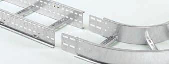
5 Save time... save money! The long-term success of Swifts cable ladder is built on design innovation and time-saving features that put us yet another rung ahead of the rest! The inclusion of integral couplers on all ladder fittings used together with our quick-fit fasteners more than halves the number of required fixings and dramatically cuts installation time and cost. Supplied as standard on all Topaz, Sapphire and Emerald fittings, this coupling technique benefits every installation type, from medium duty right through to extra heavy duty. Time-saving innovations reduce man hours and energy usage on site, including fewer components for improved assembly times PRODUCT RNGES TOPZ - MEDIUM DUTY Generally suitable for spans up to 3 m Side rail height: 100 mm vailable cabling space: 69 mm Supplied as standard in 3 m lengths Finishes: G (hot dip galvanised), D (deep galvanised) and S (stainless steel) SPPHIRE - HEVY DUTY Generally suitable for spans up to 3.5 m Side rail height: 125 mm vailable cabling space: 94 mm Supplied as standard in 3 m lengths (lengths up to 6 m available on request) Finishes: G (hot dip galvanised), D (deep galvanised), S (stainless steel) and E (powder coated) EMERLD - EXTR HEVY DUTY Generally suitable for spans up to 4 m Side rail height: mm vailable cabling space: 119 mm Supplied as standard in 3 m lengths (lengths up to 6 m available on request) Finishes: G (hot dip galvanised), D (deep galvanised) and S (stainless steel) 3


6 Legrand - global strength built on local knowledge With a 15% share of the global market, the Legrand Group is the world specialist in cable management systems and with our established Swifts, Salamandre and rena-walsall ranges, our cable management division has a firm leadership position in the UK. Sustainable development From design through to manufacturing, the Legrand Group selects materials and processes that respect people and the environment. Efficient and environmentally aware product design Product functions that help to avoid energy waste Management of manufacturing and logistics sites Integration of environmental concerns and ISO procedures at the Group s global sites. * * 84% of sites are ISO 14001:2004 accredited including all UK sites. Legrand in the UK - powered by specialists In the UK Legrand has developed a customer focused structure which harnesses the power of its market leading specialist brands to deliver innovative, integrated solutions for every phase of construction. 4
")


 from our in-house design team that can")
7 Quality assured UK manufacturing Swifts cable management ranges have been designed and manufactured at our Scarborough (UK) site since the 1960 s. nd with its own in-house galvanising facility, every product is finished to the highest possible standard following strict quality control guidelines. Legrand Electric holds ISO 9001 : 2008 Quality ssessment Registrations from Intertek Systems Certification UK and Bureau Veritas ll of Legrand s UK manufacturing sites are accredited to ISO : 2004 Environmental Management System Support from design to installation With in-depth knowledge and experience, our expert cable management team provides customers with support and advice for any installation including bespoke solutions (specials) from our in-house design team that can cope with the most demanding requirements for the most challenging projects. Registered Reg no


8 Legrand - the cable management experts Trusted for installations large and small Swifts cable ladder has been tried and tested in installations of all sizes throughout the UK and beyond, from medium duty requirements in small commercial buildings through to extra heavy duty installations in refineries and heavy industry applications. Cable management project examples Process, power and marine Transport and infrastructure General Tengiz Second Generation - Kazakhstan Vesta Wind Turbine Manufacturing Plant - Isle of Wight Norilisk Nickel Slag Cleaning Furnaces Upgrade - Siberia Ling u Nuclear Plant - China Shell E and KC upgrades - Nigeria Dukhan Facilities Upgrade - Qatar Clare Offshore Platform - Shetlands Eggborough Power Station - UK Dublin irport - Ireland Dubai irport - Dubai Kings Cross regeneration - London Channel Tunnel Rail Link - UK/France Millau Viaduct - France Tyne Tunnel - UK Heathrow T2/T3/T4/T5 - UK National Convention Centre Car Park - Qatar MOD, Corsham - Wiltshire Grand Mosque - Dubai Hong Kong Jockey Club - Hong Kong Landmark Tower - Dubai St. Davids II - Cardiff, Wales Diwan l miri Utility Building - Qatar rcapita Bank - Bahrain Tianjin Electronics Plant - China 6


9 Specification data for Intergraph, VEV and Bentley engineering software systems s part of our ongoing commitment to customer support, Legrand s Swifts cable ladder and cable tray ranges are now integrated into the following plant design modelling systems : Intergraph s PDS and Smartplant 3D VEV s PDMS Bentley Systems BBES and BRCM For many industries, achieving higher production goals within budget constraints and strict regulatory requirements is a challenging prospect. pplying engineering software allows for a high quality, fast-build, maintainable system which offers full workflow managed integration across the entire project enterprise. Using a library of intelligent Swifts cable ladder and cable tray product models inside a highly productive 3D design software system allows design teams to produce accurate and efficient cable management routing schemes, plans and procurement lists as a fully integrated part of the overall plant design. Key benefits include : Whole plant lifecycle from FEED (Front End Engineering Design), detailed design and construction through to handover, full operation and beyond Database driven applications manage all of the engineering information in one location Intelligent rules and relationships including clash detection features High project visibility and review functionality creating more efficient and productive operations High performance 3D visuals giving interactive walkthrough and realism features Making the best use of global design teams leading to concurrent engineering 7
10 PRODUCT SELECTION
11 IN THIS SECTION SWIFTS CBLE LDDER SYSTEMS Selection charts Medium duty (Topaz) Straight lengths 14 Couplers straight lengths 14 Couplers fittings 14 Flat bends 14 Inside and outside risers 14 Equal tees 15 Unequal tees 15 Branch pieces 15 4 way crosspieces 15 Straight reducers 15 Offset reducers 15 Heavy duty (Sapphire) Straight lengths 16 Couplers straight lengths 16 Couplers fittings 16 Flat bends 16 Inside and outside risers 16 Equal tees 17 Unequal tees 17 Branch pieces 17 4 way crosspieces 17 Straight reducers 17 Offset reducers 17 Extra heavy duty (Emerald) Straight lengths 18 Couplers straight lengths 18 Couplers fittings 18 Flat bends 18 Inside and outside risers 18 Equal tees 19 Unequal tees 19 Branch pieces 19 4 way crosspieces 19 Straight reducers 19 Offset reducers 19 Supports 20 ncillary items Covers 23 Fasteners 24 SWIFTRCK CHNNEL SUPPORT SYSTEM Channel and channel nuts 25 Cantilever arms 26 Framework brackets, clamps and accessories Standard fixings and fasteners CEILING SUPPORT SYSTEM Heavy duty 31 9
12 Swifts medium duty (Topaz) and heavy duty (Sapphire) cable ladder systems MEDIUM DUTY (TOPZ) LDDER COUPLERS FITTINGS (1) Widths (mm) Straight lengths (3 m) F = finish Coupler sets F = finish Fitting to fitting coupler sets F = finish Fitting to straight length fastener sets (1) F = finish Flat bends = angle r = radius F = finish Inside risers = angle r = radius F = finish Outside risers = angle r = radius F = finish Equal tees r = radius F = finish Unequal tees B = branch r = radius F = finish MEDIUM DUTY (TOPZ) ZL F ZC F ZFC F LF F M10P50 ZFB r F ZIR r F ZOR r F ZT r R F ZUT B r R F 300 ZL 300 F ZC F ZFC F LF F M10P50 ZFB 300 r F ZIR 300 r F ZOR 300 r F ZT 300 r R F ZUT 300 B r R F 450 ZL 450 F ZC F ZFC F LF F M10P50 ZFB 450 r F ZIR 450 r F ZOR 450 r F ZT 450 r R F ZUT 450 B r R F 600 ZL 600 F ZC F ZFC F LF F M10P50 ZFB 600 r F ZIR 600 r F ZOR 600 r F ZT 600 r R F ZUT 600 B r R F 750 ZL 750 F ZC F ZFC F LF F M10P50 ZFB 750 r F ZIR 750 r F ZOR 750 r F ZT 750 r R F ZUT 750 B r R F 900 ZL 900 F ZC F ZFC F LF F M10P50 ZFB 900 r F ZIR 900 r F ZOR 900 r F ZT 900 r R F ZUT 900 B r R F HEVY DUTY (SPPHIRE) Widths (mm) LDDER COUPLERS FITTINGS (1) Straight lengths (3 m) (2) F = finish Coupler sets F = finish Fitting to fitting coupler sets F = finish Fitting to straight length fastener sets (1) F = finish Flat bends = angle r = radius F = finish Inside risers = angle r = radius F = finish Outside risers = angle r = radius F = finish Equal tees r = radius F = finish Unequal tees B = branch r = radius F = finish HEVY DUTY (SPPHIRE) PL F PC F PFC F LF F M10P50 PFB r F PIR r F POR r F PT r R F PUT B r R F 300 PL 300 F PC F PFC F LF F M10P50 PFB 300 r F PIR 300 r F POR 300 r F PT 300 r R F PUT 300 B r R F 450 PL 450 F PC F PFC F LF F M10P50 PFB 450 r F PIR 450 r F POR 450 r F PT 450 r R F PUT 450 B r R F 600 PL 600 F PC F PFC F LF F M10P50 PFB 600 r F PIR 600 r F POR 600 r F PT 600 r R F PUT 600 B r R F 750 PL 750 F PC F PFC F LF F M10P50 PFB 750 r F PIR 750 R F POR 750 r F PT 750 r R F PUT 750 B r R F 900 PL 900 F PC F PFC F LF F M10P50 PFB 900 r F PIR 900 r F POR 900 r F PT 900 r R F PUT 900 B r R F (1) When connecting fittings to straight lengths, use fastener sets (not available in D finish) LFGM10P50, LFSM10P50, see p. 24 (2) 6 m lengths available on special request, contact us on +44 (0)
 K = reduced width F = finish ZB 300 R F ZX r R F Key : selecting medium duty (Topaz) fittings Replace the letters shown in red with your choice from the following options : =")
 :, 300, 450, 600, 750 r = Radius (mm) : 300, 600 22 ZB 300 300 R F ZX 300 r R F ZSR 300 K F ZLR 300 K F ZRR 300 K F 100 69 W ZB 450 300 R F ZX 450 r R F ZSR 450 K F ZLR 450 K F")

13 Branch piece F = finish 4 way crosspieces r = radius F = finish FITTINGS (1) Straight reducers K = reduced width F = finish Offset reducers (left hand) K = reduced width F = finish K K K Offset reducers (right hand) K = reduced width F = finish ZB 300 R F ZX r R F Key : selecting medium duty (Topaz) fittings Replace the letters shown in red with your choice from the following options : = ngle ( ) : 90, 60, 45 or 30 B = Branch width (mm) :, 300, 450, 600, 750, 900 F = Finish : G (hot dip galvanised after manufacture) D = (deep galvanised), S (stainless steel) K = Narrowed width when using a reducer (mm) :, 300, 450, 600, 750 r = Radius (mm) : 300, ZB R F ZX 300 r R F ZSR 300 K F ZLR 300 K F ZRR 300 K F W ZB R F ZX 450 r R F ZSR 450 K F ZLR 450 K F ZRR 450 K F ZB R F ZX 600 r R F ZSR 600 K F ZLR 600 K F ZRR 600 K F ZB R F ZX 750 r R F ZSR 750 K F ZLR 750 K F ZRR 750 K F ZB R F ZX 900 r R F ZSR 900 K F ZLR 900 K F ZRR 900 K F Inside risers. See p. 14 Flat bends. See p. 14 Branch piece F = finish 4 way crosspieces r = radius F = finish FITTINGS (1) Straight reducers K = reduced width F = finish Offset reducers (left hand) K = reduced width F = finish K K K Offset reducers (right hand) K = reduced width F = finish PB 300 R F PX r R F Key : selecting heavy duty (Sapphire) fittings Replace the letters shown in red with your choice from the following options : = ngle ( ) : 90, 60, 45 or 30 B = Branch width (mm) :, 300, 450, 600, 750, 900 F = Finish : G (hot dip galvanised after manufacture), D (deep galvanised), S (stainless steel), E (powder coated) K = Narrowed width when using a reducer (mm) :, 300, 450, 600, 750 r = Radius (mm) : 300, PB R F PX 300 r R F PSR 300 K F PLR 300 K F PRR 300 K F W PB R F PX 450 r R F PSR 450 K F PLR 450 K F PRR 450 K F PB R F PX 600 r R F PSR 600 K F PLR 600 K F PRR 600 K F PB R F PX 750 r R F PSR 750 K F PLR 750 K F PRR 750 K F PB R F PX 900 r R F PSR 900 K F PLR 900 K F PRR 900 K F Inside risers. See p. 16 Flat bends. See p
14 Swifts extra heavy duty (Emerald) cable ladder systems EXTR HEVY DUTY (EMERLD) LDDER COUPLERS FITTINGS (1) Widths (mm) Emerald straight lengths (3 m) (2) F = finish Coupler sets F = finish Fitting to fitting coupler sets F = finish Fitting to straight length fastener sets (1) F = finish Flat bends = angle r = radius F = finish Inside risers = angle r = radius F = finish Outside risers = angle r = radius F = finish Equal tees r = radius F = finish Unequal tees B = branch r = radius F = finish EXTR HEVY DUTY (EMERLD) EL F EC F EFC F LF F M10P50 EFB r F EIR r F EOR r F ET r R F EUT B r R F 300 EL 300 F EC F EFC F LF F M10P50 EFB 300 r F EIR 300 r F EOR 300 r F ET 300 r R F EUT 300 B r R F 450 EL 450 F EC F EFC F LF F M10P50 EFB 450 r F EIR 450 r F EOR 450 r F ET 450 r R F EUT 450 B r R F 600 EL 600 F EC F EFC F LF F M10P50 EFB 600 r F EIR 600 r F EOR 600 r F ET 600 r R F EUT 600 B r R F E ETW EQUL TEE 750 EL 750 F EC F EFC F LF F M10P50 EFB 750 r F EIR 750 r F EOR 750 r F ET 750 r R F EUT 750 B r R F 900 EL 900 F EC F EFC F LF F M10P50 EFB 900 r F EIR 900 r F EOR 900 r F ET 900 r R F EUT 900 B r R F (1) When connecting fittings to straight lengths, use fastener sets (not available in D finish) LFGM10P50, LFSM10P50, see p. 24 (2) 6 m lengths available on special request, contact us on +44 (0)
 K = reduced width F = finish EB 300 R F EX r R F Key : selecting extra heavy duty (Emerald) fittings Replace the letters shown in red with your choice from the following options")
 :, 300, 450, 600, 750 r = Radius (mm) : 300, 600 22 EB 300 300 R F EX 300 r R F ESR 300 K F ELR 300 K F ERR 300 K F 119 W EB 450 300 R F EX 450 r R F ESR 450 K F ELR 450 K F")
15 Branch piece F = finish 4 way crosspieces r = radius F = finish FITTINGS (1) Straight reducers K = reduced width F = finish Offset reducers (left hand) K = reduced width F = finish K K K Offset reducers (right hand) K = reduced width F = finish EB 300 R F EX r R F Key : selecting extra heavy duty (Emerald) fittings Replace the letters shown in red with your choice from the following options : = ngle ( ) : 90, 60, 45 or 30 B = Branch width (mm) :, 300, 450, 600, 750, 900 F = Finish : G (hot dip galvanised after manufacture), D (deep galvanised), S (stainless steel) K = Narrowed width when using a reducer (mm) :, 300, 450, 600, 750 r = Radius (mm) : 300, EB R F EX 300 r R F ESR 300 K F ELR 300 K F ERR 300 K F 119 W EB R F EX 450 r R F ESR 450 K F ELR 450 K F ERR 450 K F EB R F EX 600 r R F ESR 600 K F ELR 600 K F ERR 600 K F EB R F EX 750 r R F ESR 750 K F ELR 750 K F ERR 750 K F EB R F EX 900 r R F ESR 900 K F ELR 900 K F ERR 900 K F Inside risers. See p. 18 Flat bends. See p
16 Swifts medium duty (Topaz) cable ladder lengths and fittings 100 Ladder length ZL 300 G Inside riser ZIR G 90 Flat bend ZFB G Selection chart (p ) Dimensions and technical information : lengths (p. 34) ; coupler sets (p ) ; fittings (p ) Design notes (p. 112) Loading graphs (p. 34) When connecting fittings to straight lengths, use fastener sets (see below) Rung spacing : 300 mm between centres Standard radius for fittings : 300 and 600 mm Pack Cat. Nos. Straight lengths 3 m 1 ZL F mm width 1 ZL 300 F 300 mm width 1 ZL 450 F 450 mm width 1 ZL 600 F 600 mm width 1 ZL 750 F 750 mm width 1 ZL 900 F 900 mm width For technical information, see p. 34 Coupler sets Straight length to straight length 1 ZC F Supplied in pairs, with fasteners (4 per coupler) Use to couple straight lengths to straight lengths For technical information, see p Pack Cat. Nos. Fittings 1 ZFB W r F Flat bends For technical information, see p Flat bend 45 Flat bend 60 Flat bend 30 Flat bend 1 ZIR W r F Inside risers For technical information, see p. 50, 53, 56, 59 Fitting to fitting 1 ZFC F Supplied in pairs, with fasteners (4 per coupler) Use to couple fitting to fitting For technical information, see p Inside riser 60 Inside riser 45 Inside riser 30 Inside riser 1 ZOR W r F Outside risers For technical information, see p. 50, 53, 56, 59 Fastener sets Comprise M10 coach bolt and flange nut 50 LFGM10P50 Hot dip galvanised 50 LFSM10P50 Stainless steel 90 Outside riser 60 Outside riser 45 Outside riser 30 Outside riser 14
17 Swifts medium duty (Topaz) cable ladder lengths and fittings (continued) 100 Ladder length ZL 300 G Inside riser ZIR G 90 Flat bend ZFB G Selection chart (p ) Dimensions and technical information : lengths (p. 34) ; coupler sets (p ) ; fittings (p ) Design notes (p. 112) Loading graphs (p. 34) When connecting fittings to straight lengths, use fastener sets (see opposite) Rung spacing : 300 mm between centres Standard radius for fittings : 300 and 600 mm Pack Cat. Nos. Fittings (continued) Tees and crosspieces For all equal and unequal tees and crosspieces, include R in your ordering code to indicate radius dimension. See unequal tee example below Larger width/radius combinations are supplied in two indentical halves with fasteners 1 ZT W r R F Equal tees For technical information, see p. 62 Pack Cat. Nos. Fittings (continued) 1 ZB W 300 R F Branch piece vailable in 300 R only For technical information, see p ZX W r R F 4 way crosspiece For technical information, see p ZUT W B r R F Unequal tees Example : the ordering code for a hot dip galvanised unequal tee with a 300 main run (W) and a branch (B) with a 600R radius : ZUT R G For technical information, see p ZSR W K F Straight reducers For technical information, see p ZLR W K F Offset reducers left hand For technical information, see p. 73 K W W W 1 ZRR W K F Offset reducers K right hand For technical information, see p. 73 W Standard dimensions and finishes Key : selecting medium duty (Topaz) fittings. Replace the letters shown in red with your choice from the following options : W = Widths (mm) :, 300, 450, 600, 750, 900 = ngle ( ) : 90, 60, 45 or 30 B = Branch width (mm) :, 300, 450, 600, 750, 900 F = Finish : G (hot dip galvanised after manufacture), D (deep galvanised) S (stainless steel) K = Narrowed width when using a reducer (mm) :, 300, 450, 600, 750 r = Radius (mm) : 300, 600 Dimensions and finishes available to special order Contact us on +44 (0) Radius (r) (mm) : 450, 750 and 900 Rungs : Type 2 or type 3 Widths (W) (mm) : 100, 200, 250, 350, 400, 500, 550, 650, 700, 800, 850 and 950 ngles ( ) : vailable to customer s specification Finish (F) : Pickle and passivation on stainless steel K 15
18 Swifts heavy duty (Sapphire) cable ladder lengths and fittings 125 Ladder length PL 300 G Inside riser PIR G 90 Flat bend PFB G Selection chart (p ) Dimensions and technical information : lengths (p. 35) ; coupler sets (p ) ; fittings (p ) Design notes (p. 112) Loading graphs (p. 34) When connecting fittings to straight lengths, use fastener sets (see below) Rung spacing : 300 mm between centres Standard radius for fittings : 300 and 600 mm Pack Cat. Nos. Straight lengths 3 m 1 PL F mm width 1 PL 300 F 300 mm width 1 PL 450 F 450 mm width 1 PL 600 F 600 mm width 1 PL 750 F 750 mm width 1 PL 900 F 900 mm width 6 m lengths available on special request For technical information, see p. 35 Coupler sets Straight length to straight length 1 PC F Supplied in pairs, with fasteners (8 per coupler) Use to couple straight lengths to straight lengths For technical information, see p Pack Cat. Nos. Fittings 1 PFB W r F Flat bends For technical information, see p Flat bend 60 Flat bend 45 Flat bend 30 Flat bend 1 PIR W r F Inside risers For technical information, see p. 51, 54, 57, Inside riser 60 Inside riser Fitting to fitting 1 PFC F Supplied in pairs, with fasteners (8 per coupler) Use to couple fitting to fitting For technical information, see p Inside riser 30 Inside riser 1 POR W r F Outside risers For technical information, see p. 51, 54, 57, 60 Fastener sets Comprise M10 coach bolt and flange nut 50 LFGM10P50 Hot dip galvanised 50 LFSM10P50 Stainless steel 90 Outside riser 60 Outside riser 45 Outside riser 30 Outside riser 16
 Dimensions and technical information : lengths (p. 35) ; coupler sets (p. 38-45) ; fittings (p. 46-73) Design notes (p. 112) Loading graphs (p.")
19 Swifts heavy duty (Sapphire) cable ladder lengths and fittings (continued) 125 Ladder length PL 300 G Inside riser PIR G 90 Flat bend PFB G Selection chart (p ) Dimensions and technical information : lengths (p. 35) ; coupler sets (p ) ; fittings (p ) Design notes (p. 112) Loading graphs (p. 34) When connecting fittings to straight lengths, use fastener sets (see opposite) Rung spacing : 300 mm between centres Standard radius for fittings : 300 and 600 mm Pack Cat. Nos. Fittings (continued) Tees and crosspieces For all equal and unequal tees and crosspieces, include R in your ordering code to indicate radius dimension. See unequal tee example below Larger width/radius combinations are supplied in two indentical halves with fasteners 1 PT W r R F Equal tees For technical information, see p. 62 Pack Cat. Nos. Fittings (continued) 1 PB W 300 R F Branch piece. vailable in 300 R only For technical information, see p PX W r R F 4 way crosspieces For technical information, see p PUT W B r R F Unequal tees Example : the ordering code for a hot dip galvanised unequal tee with a 300 main run (W) and a branch (B) with a 600R radius : PUT R G For technical information, see p PSR W K F Straight reducers For technical information, see p PLR W K F Offset reducers left hand For technical information, see p. 73 K W W W 1 PRR W K F Offset reducers right hand For technical information, see p. 73 K W Standard dimensions and finishes Key : selecting heavy duty (Sapphire) fittings. Replace the letters shown in red with your choice from the following options : W = Widths :, 300, 450, 600, 750, 900 = ngle ( ) : 90, 60, 45 or 30 B = Branch width (mm) :, 300, 450, 600, 750, 900 F = Finish : G (hot dip galvanised after manufacture), D (deep galvanised) S (stainless steel), E (powder coated) K = Narrowed width when using a reducer (mm) :, 300, 450, 600, 750 r = Radius (mm) : 300, 600 Dimensions and finishes available to special order Contact us on +44 (0) Radius (r) (mm) : 450, 750 and 900 Rungs : Type 2 or type 3 Widths (W) (mm) : 100, 200, 250, 350, 400, 500, 550, 650, 700, 800, 850 and 950 ngles ( ) : vailable to customer s specification Finish (F) : Pickle and passivation on stainless steel K 17
20 Swifts extra heavy duty (Emerald) cable ladder lengths and fittings Ladder length EL 300 G Inside riser EIR G 90 Flat bend EFB G Selection chart (p ) Dimensions and technical information : lengths (p. 36) ; coupler sets (p ) ; fittings (p ) Design notes (p. 112) Loading graphs (p. 34) When connecting fittings to straight lengths, use fastener sets (see below) Pack Cat. Nos. Fittings Rung spacing : 300 mm between centres Standard radius for fittings : 300 and 600 mm 1 EFB W r F Flat bends For technical information, see p Pack Cat. Nos. Straight lengths 3 m 1 EL F mm width 1 EL 300 F 300 mm width 1 EL 450 F 450 mm width 1 EL 600 F 600 mm width 1 EL 750 F 750 mm width 1 EL 900 F 900 mm width 6 m lengths available on special request For technical information, see p. 36 Coupler sets Straight length to straight length 1 EC F Supplied in pairs, with fasteners (8 per coupler) Use to couple straight lengths to straight lengths For technical information, see p Flat bend 60 Flat bend 45 Flat bend 30 Flat bend 1 EIR W r F Inside risers For technical information, see p. 52, 55, 58, Inside riser 60 Inside riser Fitting to fitting 1 EFC F Supplied in pairs, with fasteners (8 per coupler) Use to couple fitting to fitting For technical information, see p Inside riser 30 Inside riser 1 EOR W r F Outside risers For technical information, see p. 52, 55, 58, 61 Fastener sets Comprise M10 coach bolt and flange nut 50 LFGM10P50 Hot dip galvanised 50 LFSM10P50 Stainless steel 90 Outside riser 60 Outside riser 45 Outside riser 30 Outside riser 18
 Dimensions and technical information : lengths (p. 36) ; coupler sets (p. 38-45) ; fittings (p. 46-73) Design notes (p. 112) Loading graphs (p.")
21 Swifts extra heavy duty (Emerald) cable ladder lengths and fittings (continued) Ladder length EL 300 G Inside riser EIR G 90 Flat bend EFB G Selection chart (p ) Dimensions and technical information : lengths (p. 36) ; coupler sets (p ) ; fittings (p ) Design notes (p. 112) Loading graphs (p. 34) When connecting fittings to straight lengths, use fastener sets (see opposite) Rung spacing : 300 mm between centres Standard radius for fittings : 300 and 600 mm Pack Cat. Nos. Fittings (continued) Tees and crosspieces For all equal and unequal tees and crosspieces, include R in your ordering code to indicate radius dimension. See unequal tee example below. Larger width/radius combinations are supplied in two indentical halves with fasteners 1 ET W r R F Equal tees For technical information, see p. 62 Pack Cat. Nos. Fittings (continued) 1 EB W 300 R F Branch piece For technical information, see p. 69 vailable in 300 R only 1 EX W r R F 4 way crosspieces For technical information, see p EUT W B r R F Unequal tees Example : the ordering code for a hot dip galvanised unequal tee with a 300 main run (W) and a branch (B) with a 600R radius : PUT R G For technical information, see p ESR W K F Straight reducers For technical information, see p ELR W K F Offset reducers left hand K For technical information, see p. 73 W W B W 1 ERR W K F Offset reducers right hand For technical information, see p. 73 K W Standard dimensions and finishes Key : selecting extra heavy duty (Emerald) fittings. Replace the letters shown in red with your choice from the following options : W = Widths (mm) :, 300, 450, 600, 750, 900 = ngle ( ) : 90, 60, 45 or 30 B = Branch width (mm) :, 300, 450, 600, 750, 900 F = Finish : G (hot dip galvanised after manufacture), D (deep galvanised) S (stainless steel) K = Narrowed width when using a reducer (mm) :, 300, 450, 600, 750 r = Radius (mm) : 300, 600 Dimensions and finishes available to special order Contact us on +44 (0) Radius (r) (mm) : 450, 750 and 900 Rungs : Type 2 or type 3 Widths (W) (mm) : 200, 250, 350, 400, 500, 550, 650, 700, 800, 850 and 950 ngles ( ) : vailable to customer s specification Finish (F) : Pickle and passivation on stainless steel K 19
 ZL 300 G Heavy duty trapeze hanger HTH 300 G Wall support bracket ZWSB G Hanger rod bracket ZRB G 90 end connector ZBG Heavy duty cantilever arm HC 300 G Dimensions and technical information (p.")
, heavy duty (Sapphire) and extra heavy duty (Emerald) ladder Heavy duty cantilever arms 1 HC W F Supplied singly without fasteners Use to fit horizontal runs")
22 Swifts cable ladder supports medium duty (Topaz), heavy duty (Sapphire) and extra heavy duty (Emerald) Ladder length (see p. 14) ZL 300 G Heavy duty trapeze hanger HTH 300 G Wall support bracket ZWSB G Hanger rod bracket ZRB G 90 end connector ZBG Heavy duty cantilever arm HC 300 G Dimensions and technical information (p ) Pack Cat. Nos. Supports For use with medium duty (Topaz), heavy duty (Sapphire) and extra heavy duty (Emerald) ladder Heavy duty cantilever arms 1 HC W F Supplied singly without fasteners Use to fit horizontal runs of ladder to flat surfaces and Swiftrack channel ll arms have slots in top flanges to accept ladder hold down brackets For technical information, see p. 74 Pack Cat. Nos Supports (continued) Wall support brackets Supplied in pairs with bracket to ladder fasteners Fit horizontal or vertical runs of ladder to vertical surfaces and Swiftrack channel For technical information, see p ZWSB F Medium duty (Topaz) 1 PWSB F Heavy duty (Sapphire) 1 EWSB F Extra heavy duty (Emerald) 90 end connectors Supplied in pairs with bracket to ladder fastener Fits ends of ladder to vertical surfaces For technical information, see p ZB F Medium duty (Topaz) 1 PB F Heavy duty (Sapphire) 1 EB F Extra heavy duty (Emerald) Heavy duty trapeze hangers 1 HTH W F Supplied singly without fasteners Support horizontal runs of ladder from overhead structure Use M12 threaded rods For technical information, see p. 75. Hanger rod brackets When hanger rod brackets are fitted to ladder, covers can not be used Supplied in pairs with bracket to ladder fasteners Support horizontal runs of ladder from overhead structure Use M10 threaded rods, (see p. 24) For technical information, see p ZRB F Medium duty (Topaz) 1 PRB F Heavy duty (Sapphire) 1 ERB F Extra heavy duty (Emerald) Key : selecting medium duty (Topaz), heavy duty (Sapphire) and extra heavy duty (Emerald) supports. Replace the letters shown in red with your choice from the following options : W = Widths :, 300, 450, 600, 750, 900 F = Finish : G (hot dip galvanised after manufacture), D (deep galvanised) S (stainless steel), E (powder coated) 20
 ZL 300 G Earth continuity connector PLF EB Bendable connector ZH G Boltable angled hold down bracket ZP G Hold down clip ZF G Dimensions and technical information (p.")

23 Swifts cable ladder ancillary items medium duty (Topaz), heavy duty (Sapphire) and extra heavy duty (Emerald) Boltable hold down bracket ZN G Hold down bracket ZJ G Flexible expansion coupler ZE G Ladder length (see p. 14) ZL 300 G Earth continuity connector PLF EB Bendable connector ZH G Boltable angled hold down bracket ZP G Hold down clip ZF G Dimensions and technical information (p ) Dimensions and technical information coupler sets (p ) Pack Cat. Nos. ncillary items Bendable connectors Supplied in pairs with fasteners For fabricating fittings on site to make up bends, reducers and compensate for misalignment of straight lengths For technical information, see p ZH F Medium duty (Topaz) 1 PH F Heavy duty (Sapphire) 1 EH F Extra heavy duty (Emerald) Pack Cat. Nos. ncillary items (continued) Hold down clip Supplied singly without fasteners Fits ladder to flat surfaces, Swiftrack channel or heavy duty trapeze hangers which have slots in the top flange to accept fasteners For insulated version, add IN after Cat. No., eg. ZF IN F. (Note : note available in D finish) For technical information, see p ZF F Medium duty (Topaz) 1 PF F Heavy duty (Sapphire) 1 EF F Extra heavy duty (Emerald) Flexible expansion couplers Supplied in pairs with fasteners Provide a semi-flexible joint to compensate for relative movement when spanning separate structures or changes in ladder lengths due to temperature variation For technical information, see p ZE F Medium duty (Topaz) 1 PE F Heavy duty (Sapphire) 1 EE F Extra heavy duty (Emerald) Earth continuity connectors 10 PLFEB Medium duty (Topaz), heavy duty (Sapphire), extra heavy duty (Emerald) M6 brass fasteners included in pack Copper braid and copper lugs both in electrotinned finish Conductor area : 16 mm 2 For technical information, see p. 79 Key : selecting medium duty (Topaz), heavy duty (Sapphire) and extra heavy duty (Emerald) supports. Replace the letters shown in red with your choice from the following options : W = Widths :, 300, 450, 600, 750, 900 F = Finish : G (hot dip galvanised after manufacture), D (deep galvanised) S (stainless steel), E (powder coated) Hold down bracket Supplied singly without fasteners Fits ladder to flat surfaces, Swiftrack channel, cantilever arms or heavy duty trapeze hangers which have slots in the top flange to accept fasteners For insulated version, add IN after Cat. No., eg. ZJ IN F. (Note : note available in D finish) For technical information, see p ZJ F Medium duty (Topaz) 1 PJ F Heavy duty (Sapphire) 1 EJ F Extra heavy duty (Emerald) Boltable hold down bracket Supplied singly with bracket to ladder fastener Fits ladder to Swiftrack channel in fabricated steel support structure For technical information, see p ZN F Medium duty (Topaz) 1 PN F Heavy duty (Sapphire) 1 EN F Extra heavy duty (Emerald) Boltable angled hold down brackets Supplied in handed pairs with bracket to ladder fastener Fits ladder to heavy duty cantilever arms and trapeze hangers which have slots in the side flange to accept fasteners For technical information, see p ZP F Medium duty (Topaz) 1 PP F Heavy duty (Sapphire) 1 EP F Extra heavy duty (Emerald) 21
 Pack Cat. Nos. ncillary items (continued) Straight dividers 3 0 m Supplied with fasteners For technical information, see p.")

 1 PV F")
24 Swifts cable ladder ancillary items (continued) Topaz, Sapphire and Emerald Curved divider ZCUR G Straight divider ZDV G Dropout DO 300 G Vertical hinged connector ZV G rticulated riser ZR 300 G Tee bracket ZTB G Dimensions and technical information (p ) Pack Cat. Nos. ncillary items (continued) Straight dividers 3 0 m Supplied with fasteners For technical information, see p ZDV F Medium duty (Topaz) 1 PDV F Heavy duty (Sapphire) 1 EDV F Extra heavy duty (Emerald) Curved dividers 1 0 m Supplied with fasteners Drill on site to suit rung position For technical information, see p ZCUR F Medium duty (Topaz) 1 PCUR F Heavy duty (Sapphire) 1 ECUR F Extra heavy duty (Emerald) Vertical hinged connectors Supplied in sets comprising four plates and fasteners Use with straight lengths to form risers or solve minor misalignment problems on site When used with tee bracket, vertical hinged connectors can offset tee branch For technical information, see p ZV F Medium duty (Topaz) 1 PV F Heavy duty (Sapphire) 1 EV F Extra heavy duty (Emerald) rticulated risers Set comprises three ladder sections and the necessary vertical hinged connectors with fasteners Use to form risers or solve most misalignment problems on site For technical information, see p ZR W F Medium duty (Topaz) 1 PR W F Heavy duty (Sapphire) 1 ER W F Extra heavy duty (Emerald) Pack Cat. Nos. ncillary items (continued) Dropout plate Supplied with fasteners Use to provide local support for cables as they exit a cable ladder run between rungs For technical information, see p DO W F ll ladder types Rail-to-rail dropout brackets Supplied in pairs with fasteners Use to attach a vertical run of ladder or tray beneath a horizontal main ladder run For technical information, see p M F For ladder to ladder connection or Tray to ladder connection Tee brackets Supplied in pairs with fasteners Use to create a branch of a straight ladder run For technical information, see p ZTB F Medium duty (Topaz) 1 PTB F Heavy duty (Sapphire) 1 ETB F Extra heavy duty (Emerald) Stop ends Supplied singly with fasteners. Use to terminate a ladder run, or to fix the end of a run to a vertical surface For technical information, see p ZSW F Medium duty (Topaz) 1 PSW F Heavy duty (Sapphire) 1 ESW F Extra heavy duty (Emerald) Key : selecting ancillary items. Replace the letters shown in red with your choice from the following options : W = Widths (mm) :, 300, 450, 600, 750, 900 F = Finish : G (hot dip galvanised after manufacture), D (deep galvanised) S (stainless steel), E (powder coated) 22
 Pack Cat. Nos.")
 for straight reducers and offset reducers (see p.")
25 Swifts cable ladder ancillary items (continued) and covers Topaz, Sapphire and Emerald Fitting cover FBCV G ncillary mounting bracket MB 300 G ncillary mounting plate MP G Straight ventilated cover CV 300 G Short reducer bracket ZR G Dimensions and technical information (p ) Pack Cat. Nos. ncillary items (continued) Short reducer brackets Supplied singly with fasteners Use to form a reducer on site Straight reducer use in pairs Offset reducer use singly with straight coupler W Y Offset reducer Y = W - K K Y W W = main ladder mm K = reduced ladder mm Y Y K Straight reducer Y = W - K 2 To calculate (Y) for straight reducers and offset reducers (see p. 90) For technical information, see p ZR Y F Medium duty (Topaz) 1 PR Y F Heavy duty (Sapphire) 1 ER Y F Extra heavy duty (Emerald) ncillary mounting bracket Supplied singly with bracket to ladder fasteners For technical information, see p MB W F ll ladder types ncillary mounting plate Supplied singly with bracket to ladder fasteners For technical information, see p MP F ll ladder types For rung mounting or Side rail mounting Pack Cat. Nos. Covers Supplied with clips and fasteners Covers for both closed and ventilated installations are common (except when using inside and outside risers, see below) 600 mm wide and above are overlap jointed for rigidity For technical information, see p Straight covers 3 0 m 1 CV W F vailable in -900 mm widths Example : To cover a 300 mm wide Z, P or E ladder length with a straight hot dip galvanised cover, ordering code for cover = CV 300 G 1 Covers for fittings (except risers) To order a cover for a fitting, (except risers) remove first letter of fitting product code (Z, P or E) and add CV before your chosen dimensions Example : Product code = PFB G Cover code = FB CV G Riser covers are specific for Z, P or E Inside riser closed covers 1 ZIRC W r F Medium duty (Topaz) 1 PIRC W r F Heavy duty (Sapphire) 1 EIRC W r F Extra heavy duty (Emerald) Inside riser ventilated covers 1 ZIRV W r F Medium duty (Topaz) 1 PIRV W r F Heavy duty (Sapphire) 1 EIRV W r F Extra heavy duty (Emerald) Outside riser closed covers 1 ZORC W r F Medium duty (Topaz) 1 PORC W r F Heavy duty (Sapphire) 1 EORC W r F Extra heavy duty (Emerald) Outside riser ventilated covers 1 ZORV W r F Medium duty (Topaz) 1 PORV W r F Heavy duty (Sapphire) 1 EORV W r F Extra heavy duty (Emerald) Cable support bracket For technical information, see p CSB F Supplied singly with fasteners Cable ties not included Key : selecting for ancillary items and covers. Replace the letters shown in red with your choice from the following options : W = Widths :, 300, 450, 600, 750, 900 Y = Ladder width reduction = ngle ( ) : 90, 60, 45 or 30 F = Finish : G (hot dip galvanised after manufacture), D (deep galvanised) S (stainless steel), E (powder coated) K = Narrowed width when using a reducer (mm) :, 300, 450, 600, 750 r = Radius (mm) : 300,


26 Swifts cable ladder fasteners medium duty (Topaz), heavy duty (Sapphire) and extra heavy duty (Emerald) SW12 HN12 SS1225 RB0616 SS1235 FW10 SSG0616 LFGM10P50 RB0640 RBG0612 TR06 RC06 Pack Cat. Nos. Fastener sets Comprise M10 coach bolt and flange nut 50 LFGM10P50 Hot dip galvanised 50 LFSM10P50 Stainless steel Fasteners Hexagon head setscrews Electroplated zinc 200 SS0616 M6 x SS0620 M6 x SS0625 M6 x SS0630 M6 x SS1016 M10 x SS1020 M10 x SS1025 M10 x SS1030 M10 x SS1035 M10 x SS1040 M10 x SS1045 M10 x SS1050 M10 x SS1060 M10 x SS1220 M12 x SS1225 M12 x SS1230 M12 x SS1235 M12 x SS1240 M12 x SS1250 M12 x 50 Hot dip galvanised 200 SSG0616 M6 x SSG0620 M6 x SSG0625 M6 x SSG0630 M6 x 30 Flat washers Electroplated zinc 500 FW06 M6 500 FW08 M8 500 FW10 M FW12 M12 Shakeproof washers Electroplated zinc 400 SW06 M6 400 SW08 M8 400 SW10 M SW12 M12 Pack Cat. Nos. Fasteners (continued) Hexagon nuts Electroplated zinc 500 HN06 M6 500 HN08 M8 500 HN10 M HN12 M12 Roofing nuts and bolts Electroplated zinc 200 RB0612 M6 x RB0616 M6 x RB0620 M6 x RB0625 M6 x RB0630 M6 x RB0640 M6 x RB0650 M6 x 50 Hot dip galvanised 100 RBG0612 M6 x RBG0616 M6 x 16 Stainless steel 100 RB0612 S M6 x RB0616 S M6 x RB0620 S M6 x 20 Threaded rods Electroplated zinc 1 TR06 M6 x 3 m 1 TR08 M8 x 3 m 1 TR10 M10 x 3 m 1 TR12 M12 x 3 m Threaded rod connectors Electroplated zinc 1 RC06 M6 1 RC08 M8 1 RC10 M10 1 RC12 M12 24
 Design notes (p.")

27 Swiftrack channel support system channels and channel nuts PN101 SC400 3M SC410 3M SC401 3M SC403 3M PN102 PN100 Typical applications (p ) Dimensions and technical information (p ) Design notes (p. 112) Channel and brackets are manufactured to BS 6946 specifications for metal channel cable support systems for electrical installations and calculations for loading are in accordance with BS 5950 : Part structural use of steelwork in buildings, code of practice for cold formed thin gauge sections Pack Cat. Nos. Single channels - plain The standard finish for channel is pre-galvanised mild steel to BS EN For other finishes add the appropriate suffix G = hot dip galvanised after manufacture to BS EN ISO 1461 S = stainless steel to BS EN grade (equivalent to S316L31) Channels SC210 and SC410 are not available in S finish Examples : SC200 3M G for hot dip galvanised SC400 3M S for stainless steel For technical information, see p. 99 Standard channel 1 SC200 3M 41 x 21 mm, 3 m length 1 SC200 6M 41 x 21 mm, 6 m length 1 SC400 3M 41 x 41 mm, 3 m length 1 SC400 6M 41 x 41 mm, 6 m length Light gauge channel 1 SC210 3M 41 x 21 mm, 3 m length 1 SC410 3M 41 x 41 mm, 3 m length Back-to-back channel For technical information see p SC401 3M 41 x 83 mm, 3 m length 1 SC401 6M 41 x 83 mm, 6 m length Pack Cat. Nos. Single channels - slotted For technical information, see p. 99 Standard channel 1 SC203 3M 41 x 21 mm, 3 m length 1 SC203 6M 41 x 21 mm, 6 m length 1 SC403 3M 41 x 41 mm, 3 m length 1 SC403 6M 41 x 41 mm, 6 m length Light gauge channel 1 SC213 3M 41 x 21 mm, 3 m length 1 SC413 3M 41 x 41 mm, 3 m length Channel nuts For use with all channel M12 channel nuts should always be used for maximum load conditions The standard finish for all nuts is zinc plated to BS 3382 : Part 2 For stainless steel, add the suffix S Example : PN101S For hot dip galvanised, add the suffix G Example : PN101G Fasteners : Use hexagon head setscrews (see p. 29) For technical information, see p. 101 Long springs For use with 41 mm deep channel 100 PN061 M6 100 PN081 M8 100 PN101 M PN121 M12 Short springs For use with 21 mm deep channel 100 PN062 M6 100 PN082 M8 100 PN102 M PN122 M12 Other fasteners and finishes available to special order Contact us on +44 (0) No springs For use on all channel depths 100 PN060 M6 100 PN080 M8 100 PN100 M PN120 M12 25


28 Swiftrack channel support system cantilever arms S756 S762 S772 S752 S757 S792 Dimensions and technical information (p ) Pack Cat. Nos. Cantilever arms In addition to the cantilever arms listed, there are many other specialist support brackets for use with cable ladder These are detailed in the relevant sections in this catalogue Cantilever arms Requires only one bolt for quick fixing and is used with open face at the top For technical information, see p S750 mm 1 S mm 1 S mm 1 S mm 1 S mm 1 S mm 1 S mm Cantilever arms, universal Two bolt fixing. Can be used with open face at the top or bottom For technical information, see p S760 mm 1 S mm 1 S mm 1 S mm 1 S mm 1 S mm 1 S mm Cantilever arms, side Two bolt fixing. Can be used with open face on the left or right For technical information, see p S790 mm 1 S mm 1 S mm 1 S mm 1 S mm 1 S mm 1 S mm Pack Cat. Nos. Cantilever arms (continued) Cantilever arms, double channel Two bolt fixing with extra support Open face top and bottom For technical information, see p S770 mm 1 S mm 1 S mm 1 S mm 1 S mm 1 S mm 1 S mm Cantilever arm bracket 1 S756 Used to provide extra support to a horizontal run of channel For technical information see p. 103 Non-standard cantilever arms available to special order Contact us on +44 (0)
29 Swiftrack channel support system framework brackets 90 brackets Cat. No. SB500 Cat. No. SB501 Cat. No. SB502 Cat. No. SB503 Cat. No. SB Cat. No. SB505 Cat. No. SB550 Cat. No. SB551 Cat. No. SB552 Cat. No. SB556 Square and splice plates Square plates Hole Cat. Nos. size SB M6 SB M8 SB M10 SB M12 Splice plate (1) Splice plate (1) Splice plate (1) Splice plate (1) Cat. No. SB507 Cat. No. SB508 Cat. No. SB509 Cat. No. SB510 Z brackets U brackets (2) Cat. No. SB511 Cat. No. SB513 Cat. No. SB514 Cat. No. SB515 ngle brackets 90 ϑ Obtuse angle brackets Cat. Nos. ngle SB SB SB SB ϑ 90 cute angle brackets Cat. Nos. ngle SB SB SB T plates and brackets T plate T plate T bracket Cross plate 90 T bracket 45 T bracket Cat. No. SB554 Cat. No. SB555 Cat. No. SB603 Cat. No. SB603+ Cat. No. SB606 (3) Cat. No. SB607 (3) (1) Splice plates holes spaced at 45 mm centres (2) Hole on one side of bracket only (3) SB606 and SB607 are not available in S (stainless steel) finish For technical information : see p
30 Swiftrack channel support system framework brackets (continued) Jointing brackets and channels Base plates Channel jointing bracket Jointing channel for SC200 channel Jointing channel for SC400 channel Single channel base plate 40 Double channel base plate Cat. No. SB518 Cat. No. SB650 Cat. No. SB651 Cat. No. SB704 Cat. No. SB705 L brackets Wing brackets L bracket Right hand Left hand 90 L corner L corner bracket bracket lug wing bracket 3 lug wing bracket ngled wing bracket Cat. No. SB600 Cat. No. SB601 (2) Cat. No. SB602 (2) Cat. No. SB700 Cat. No. SB701 Cat. No. SB707 (2) Gusseted brackets Shelf brackets Single channel gusseted bracket Double channel gusseted bracket Outer holes Ø Outer holes Ø Cat. No. SB702 Cat. No. SB706 Beam, window beam and toe beam clamps Cat. No. SB703 Beam clamp (3) Beam clamp (3) Window beam clamp (3) Window beam clamp (3) Beam clamp (3) (1) (1) (1) 40 (1) 65 (1) (1) 40 (1) (1) 40 (1) (1) (1) 22 (1) 22 (1) (1) 46 (1) 12 Cat. No. SC850 Cat. No. SC851 Cat. No. SC852/21 Cat. No. SC852/41 Cat. No. SC852/82 Beam clamp Beam clamp (3) (3) Toe beam clamp Beam clamp Beam clamp (3) (3) Beam clamp (3) (3) (1) 23 (1) 20 (1) (1) 67 (1) 17 Cat. No. SC853 Cat. No. SC854 Cat. No. SC856 (4) Cat. No. ZC1 (5) Cat. No. FL2 (5) Cat. No. SC855 Pipe diameter Cat. Nos. (mm) SP SP SP SP SP SP SP Pipe clamps (6) Pipe diameter Cat. Nos. (mm) SP SP Channel end caps (7) Cat. Nos. SC950B SC950W 19 Channel accessories Channel end caps (8) Cat. Nos. SC951B SC951W (1) Indicates inside dimensions (2) SB601, SB602 and SB707 are not available in S (stainless steel) finish (3) Beam clamps are supplied with nuts, bolts, cone point screws and U bolts where shown (4) Requires 2 setscrews and channel nuts for fixing (not included) (5) Stainless steel finish is not available (6) ll pipe clamps are available in pre-galvanised and stainless steel finishes (7) For SC400, SC401 and SC403 channels (8) For SC200, SC201 and SC203 channels (1) 46 (1) 12 Closure strips ø Cat. Nos. SC952 SC953
31 Swiftrack channel support systems standard fixings and fasteners Hexagon head Cone point Hexagon setscrews screws nuts Electroplated roofing nuts and bolts Hot dip galvanised roofing nuts and bolts Pack Cat. Nos. Size Hexagon head setscrews ELECTROPLTED ZINC 200 SS0616 M6 x SS0620 M6 x SS0625 M6 x SS0630 M6 x SS0820 M8 x SS0825 M8 x SS0830 M8 x SS0835 M8 x SS0840 M8 x SS0850 M8 x SS1016 M10 x SS1020 M10 x SS1025 M10 x SS1030 M10 x SS1035 M10 x SS1040 M10 x SS1045 M10 x SS1050 M10 x SS1060 M10 x SS1220 M12 x SS1225 M12 x SS1230 M12 x SS1235 M12 x SS1240 M12 x SS1250 M12 x 50 HOT DIP GLVNISED 200 SSG0612 M6 x SSG0616 M6 x SSG0620 M6 x SSG0635 M6 x 35 Pack Cat. Nos. Size Cone point screws ELECTROPLTED ZINC 100 CP1035 M10 x 35 STINLESS STEEL 100 CP1035 S M10 x 35 Hexagon nuts ELECTROPLTED ZINC 500 HN06 M6 500 HN08 M8 200 HN10 M HN12 M12 Roofing nuts and bolts ELECTROPLTED ZINC 200 RB0612 M6 x RB0616 M6 x RB0620 M6 x RB0625 M6 x RB0630 M6 x RB0640 M6 x RB0650 M6 x 50 HOT DIP GLVNISED 100 RBG0612 M6 x RBG0616 M6 x 16 STINLESS STEEL 100 RB0612 S M6 x RB0616 S M6 x RB0620 S M6 x 20 29
32 Swiftrack channel support systems standard fixings and fasteners (continued) Flat Roofing Penny Shakeproof Tray Threaded Threaded rod Eye washers washers washers washers washers rods connectors bolts Pack Cat. Nos. Size Flat washers ELECTROPLTED ZINC 500 FW06 M6 500 FW08 M8 500 FW10 M FW12 M12 Roofing washers HOT DIP GLVNISED 500 RWG06 M6 Penny washers ELECTROPLTED ZINC 400 PW06 M6 x PW08 M8 x PW10 M10 x PW12 M12 x 40 Shakeproof washers ELECTROPLTED ZINC 400 SW06 M6 400 SW08 M8 400 SW10 M SW12 M12 Tray washers ELECTROPLTED ZINC 400 TW06 M6 x 20 HOT DIP GLVNISED 100 TWG06 M6 x 20 Pack Cat. Nos. Size Threaded rod ELECTROPLTED ZINC 3 m TR06 M6 x 3 m 3 m TR08 M8 x 3 m 3 m TR10 M10 x 3 m 3 m TR12 M12 x 3 m Threaded rod connectors ELECTROPLTED ZINC 1 RC06 M6 1 RC08 M8 1 RC10 M10 1 RC12 M12 Eye bolts ELECTROPLTED ZINC 1 EB06 M6 x 80 1 EB08 M8 x 80 1 EB10 M10 x 80 30
33 Ceiling support system heavy duty End plate profile Ceiling support Extension profile Dimensions and technical information (p. 109) The dedicated ceiling support system allows for a flexible, multi-tiered approach for single or double sided loads with a maximum cantilever arm width of 700 mm to accept Swifts cable ladders up to 600 mm wide, either lidded or unlidded Conform to IEC Pack Cat. Nos. Support system Pack Cat. Nos. Support system (continued) Ceiling supports Moment 1% deflection 780 Nm Symmetrical load N Including protection end cap Ceiling fixings not included Length mm mm mm mm mm mm mm mm mm mm mm mm mm mm mm mm mm Extension profiles Moment Nm mm mm Cantilever arms Fix to profi le with 1 x M10 x 25 mm carriage bolt + washer + hexagon nut Width mm mm mm mm mm mm Ceiling bracket Lock to profile with 2 x M10 x 25 mm carriage bolt + washer + hexagon nut djustable between -30 and +30 End plate profile Lock to profile with 2 x M10 x 25 mm carriage bolt + washer + hexagon nut Profile connector Lock to profile with 4 x M10 x 20 mm hexagon bolt + washer + hexagon nut For fasteners, see p For technical information, see p
34 TECHNICL SPECIFICTIONS

35 IN THIS SECTION SWIFTS CBLE LDDER SYSTEMS Straight lengths Medium duty (Topaz) 34 Heavy duty (Sapphire) 35 Extra heavy duty (Emerald) 36 Rung details / diagonal bracing 37 Couplers straight lengths Straight length to straight length couplers Flexible expansion couplers 40 Connectors bendable and vertical hinged Pre-fabrication of cable ladder runs 43 Identification and recognition of fittings 43 Couplers fittings Integral fitting couplers 44 Fitting to fitting couplers Fittings Flat bends Inside and outside risers Equal and unequal tees Branch pieces 69 4 way crosspieces Straight and offset reducers Supports Heavy duty cantilever arms 74 Heavy duty trapeze hangers 75 Hanger rod brackets 76 Wall support brackets end connectors 78 ncillary items Earth continuity connectors 79 Hold down clips and brackets Boltable hold down brackets 82 Boltable angled hold down brackets 83 Dividers - straight / curved 84 rticulated risers Dropout plates 87 Rail to rail dropout plates 88 Tee brackets 89 Short reducer brackets 90 ncillary mounting brackets and plates Cable support brackets 93 Stop ends 94 Covers Straight lengths and fittings SWIFTRCK CHNNEL SUPPORT SYSTEM Single channels plain and slotted 99 Back-to-back channels 100 ssembly fasteners and channel nuts 101 Cantilever arms Framework brackets Beam clamps, pipe clamps and accessories CEILING SUPPORT SYSTEM Heavy duty
36 Swifts straight lengths medium duty (Topaz) 100 Dimensions and weights Loading graphs Load tests carried out to BS EN test type 1 (safety factor 1 7+ and joint in middle of span) or test type 4 (safety factor 1 7+ and joint in middle of span with rung slot over support) Load tests carried out over 2 m, 3 m and 4 m spans using 3 m lengths Safe working load should include all cable loads and any other additional loads (e.g. wind, snow) When installed, inner span deflection will vary depending on joint positions but will typically be about half of test end span deflection shown below End span deflection at Max. SWL (mm) For cable load capacity see loading graphs opposite Dimensions 300 Rung pitch Medium duty (Topaz) Cat. No. ZL W F Maximum safe working load (kg/m) G + D finish Span length (m) Ø7 5 drain holes at 300 centres Weights Width (W) W + 40 W - 4 Internal width 69 Cat. Nos. ZL F ZL 300 F ZL 450 F ZL 600 F ZL 750 F ZL 900 F Weight (kg) Ø7 5 earth bonding holes at 75 pitch 22 x 11 bolt slots at 37 5 pitch ll weights given are in kilograms (kg) and are for a 3 m straight length in hot dip galvanised G finish To obtain the appropriate component weight in other finishes, multiply the given weight by the following factors : Deep galvanised (D) x 1 07 Stainless steel (S) x 0 94 Powder coated (E) x 0 97 Graph showing safe working load vs span with deflections shown at SWL Finishes Standard stocked finish : G Hot dip galvanised after manufacture to BS EN ISO 1461 : 2009 dditional finishes : D Deep galvanised high silicon steel made from BS EN : 2004 Grade S355JOWP S Stainless steel to BS EN grade (equivalent to 316L31) Pickle and passivation is available to special order E Powder coated (to customer s specification) Sheared steel (particularly stainless steel) does have relatively sharp edges and protective gloves must be worn during handling Gauge Standard side rail = 1 5 mm Key : Replace the letter shown in red with your choice from the following options : F = Finish : G (hot dip galvanised after manufacture) D (deep galvanised) S (stainless steel) E (powder coated) ll dimensions (mm) are nominal Rung details : see p. 37 Coupler sets : see p
37 Swifts straight lengths heavy duty (Sapphire) 125 Dimensions and weights For cable load capacity see loading graphs opposite Dimensions Heavy duty (Sapphire) Cat. No. PL W F Loading graphs Load tests carried out to BS EN test type 1 (safety factor 1 7+ and joint in middle of span) or test type 4 (safety factor 1 7+ and joint in middle of span with rung slot over support) Load tests carried out over 3 m, 4 m and 5 m spans using 3 m lengths and 6 m spans using 6 m lengths Safe working load should include all cable loads and any other additional loads (e.g. wind, snow) For spans greater than 5 m : data is for 6 m long ladders only For spans 5 m and less : data can be used for 3 m or 6 m long lengths For spans greater than 5 m : ladder is not suitable for use with dynamic loads (e.g. wind, snow) When installed, inner span deflection will vary depending on joint positions but will typically be about half of test end span deflection shown below End span deflection at Max. SWL (mm) (1) Rung pitch Ø7 5 drain holes at 300 centres or Standard length = 3000 mm (6000 mm available on special request) W + 40 Ø7 5 earth W bonding holes 22 Internal width at 75 pitch Weights Width (W) Cat. Nos. PL F PL 300 F PL 450 F PL 600 F PL 750 F PL 900 F Weight (kg) x 11 bolt slots at 37 5 pitch ll weights given are in kilograms (kg) and are for a 3 m straight length in hot dip galvanised G finish To obtain the appropriate component weight in other finishes, multiply the given weight by the following factors : Deep galvanised (D) x 1 07 Stainless steel (S) x 0 94 Powder coated (E) x 0 97 Maximum safe working load (kg/m) Span length (m) Graph showing safe working load vs span with deflections shown at SWL (1) Defl ections shown for G fi nish. D and S fi nish defl ections on application, please contact us on +44 (0) G + D finish S finish Finishes Standard stocked finish : G Hot dip galvanised after manufacture to BS EN ISO 1461 : 2009 dditional finishes : D Deep galvanised high silicon steel made from BS EN : 2004 Grade S355JOWP S Stainless steel to BS EN grade (equivalent to 316L31) Pickle and passivation is available to special order E Powder coated (to customer s specification) Sheared steel (particularly stainless steel) does have relatively sharp edges and protective gloves must be worn during handling Gauge Standard side rail = 1 5 mm Non-standard side rail = 2 0 mm Key : Replace the letter shown in red with your choice from the following options : F = Finish : G (hot dip galvanised after manufacture) D (deep galvanised) S (stainless steel) E (powder coated) ll dimensions (mm) are nominal Rung details : see p. 37 Coupler sets : see p
38 Swifts straight lengths extra heavy duty (Emerald) Extra heavy duty (Emerald) For cable load capacity see loading graphs opposite Extra heavy duty (Emerald) Cat. No. EL W F Loading graphs Load tests carried out to BS EN test type 1 (safety factor 1 7+ and joint in middle of span) or test type 4 (safety factor 1 7+ and joint in middle of span with rung slot over support) Load tests carried out over 3 m, 4 m and 5 m spans using 3 m lengths and 6 m spans using 6 m lengths Safe working load should include all cable loads and any other additional loads (e.g. wind, snow) For spans greater than 5 m : data is for 6 m lengths only For spans 5 m and less : data can be used for 3 m or 6 m lengths For spans greater than 5 m : ladder is not suitable for use with dynamic loads (e.g. wind, snow) When installed, inner span deflection will vary depending on joint positions but will typically be about half of test end span deflection shown below End span deflection at Max. SWL (mm) (1) Dimensions 300 Rung pitch or Standard length = 3000 mm (6000 mm available on special request) W + 40 Ø7 5 earth W bonding holes 22 at 75 pitch Internal width Maximum safe working load (kg/m) Span length (m) Graph showing safe working load vs span with deflections shown at SWL G + D finish S finish (1) Defl ections shown for G fi nish. D and S fi nish defl ections on application, please contact us on +44 (0) Ø7 5 drain holes at 300 centres Weights Width (W) Cat. Nos. EL F EL 300 F EL 450 F EL 600 F EL 750 F EL 900 F Weight (kg) x 11 bolt slots at 37 5 pitch ll weights given are in kilograms (kg) and are for a 3m straight length in hot dip galvanised G finish To obtain the appropriate component weight in other finishes, multiply the given weight by the following factors : Deep galvanised (D) x 1 07 Stainless steel (S) x 0 94 Powder coated (E) x 0 97 Finishes Standard stocked finish : G Hot dip galvanised after manufacture to BS EN ISO 1461 : 2009 dditional finishes : D Deep galvanised high silicon steel made from BS EN : 2004 Grade S355JOWP S Stainless steel to BS EN grade (equivalent to 316L31) Pickle and passivation is available to special order E Powder coated (to customer s specification) Sheared steel (particularly stainless steel) does have relatively sharp edges and protective gloves must be worn during handling Gauge Standard side rail = 2 0 mm Key : Replace the letter shown in red with your choice from the following options : F = Finish : G (hot dip galvanised after manufacture) D (deep galvanised) S (stainless steel) E (powder coated) ll dimensions (mm) are nominal Rung details : see p. 37 Coupler sets : see p
39 Swifts cable ladder rungs for straight lengths and fittings Swifts cable ladder systems diagonal bracing straight lengths Rung details Type 1 rungs are used as standard Type 2 and 3 are only available to special order Type 3 is not available in deep galvanised finish Types 1 and 3 can be supplied in any combination to special order Options and dimensions Standard Type Diagonal bracing The effect of lateral loads on spans over 5 m or 6 m can be much reduced by adding diagonal bracing Bracing is achieved by fitting a ladder Type 1 rung section, cut to length from a 3 m length supplied, diagonally across the underside of the ladder as shown in the illustration below. Diagonal bracing can be fitted to either heavy duty (Sapphire) or extra heavy duty (Emerald) ladders medium duty (Topaz) is not suited to these long spans Installation (typical) Support Diagonal brace bolted to underside of alternate ladder rungs Support 35 x Special order only Type 2 Coupler Plan view 1 8 m typical Ladder rung 6 m span Diagonal brace (3 m long) cut to length as required 7 5 Ø drain holes at 100 centres 20 x 7 25 Type x Slot pattern may differ on stainless steel type 3 rungs Contact us on +44 (0) Couplers are best located over the point of support to provide additional local reinforcement of the ladder side rails. Details on long span installations are given on p. 129 ssembly Fasteners (not included) B C D M10 Swiftrack channel nut (PN 100) B Ladder rung C 40 x 40 x 6 square washer, Cat. No. SB506/10 D Diagonal brace (type 1 rung) E M10 form washer F M10 x 25 Grade 8.8 setscrew hot dip galvanised E F Fastener finishes For ladders with S finish, fasteners are corrosion resistant stainless Grade 470 ll dimensions (mm) are nominal 37
40 Swifts cable ladder couplers and fasteners straight length to straight length couplers Couplers are used for joining together straight lengths in the medium duty (Topaz), heavy duty (Sapphire) and extra heavy duty (Emerald) ranges Fittings in these ranges have integral couplers. See p. 44 for more information Even when ladders are cut to length, the slots in the coupler will always align with the slots in the ladder side rail Supplied in pairs with the appropriate quantity of fasteners Installation (typical) ssembly Slide the couplers under the return flanges of one ladder side rail and loosely fit a single fastener to each coupler to hold it in place Slide the second ladder over both couplers, adjust each coupler position to align the slots with the side rail slots and secure with all fasteners Medium duty (Topaz) ZCF Note Bolts should be inserted through the side rail first For location of coupler and position of fasteners, see below Fastener positioning Medium duty (Topaz) Supplied in pairs, with fasteners (4 per coupler) Heavy duty (Sapphire) PCF When bolting to cut ends adjust coupler to ensure 4 bolts can be inserted Note When connecting straight lengths to straight lengths even when ladder is cut to length, the slots in the coupler will always align with slots in the ladder side rail Heavy duty (Sapphire) and extra heavy duty (Emerald) Supplied in pairs, with fasteners (8 per coupler) When bolting to cut ends adjust coupler to ensure 8 bolts can be inserted Note When connecting straight lengths to straight lengths even when ladder is cut to length, the slots in the coupler will always align with slots in the ladder side rail Ladder range Topaz Sapphire Emerald Cat. Nos. ZCF PCF ECF Quantity of fasteners per coupler Extra heavy duty (Emerald) ECF Joggles are formed in the bottom of PC and EC couplers to allow easy installation of ladder cut lengths When connecting straight lengths to fittings, use fastener sets, see p. 44 For additional types of straight length to straight length couplers and fasteners, see p Key : Replace the letter shown in red with your choice from the following options : F = Finish : G (hot dip galvanised after manufacture) D (deep galvanised) S (stainless steel) E (powder coated) ll dimensions (mm) are nominal Straight lengths : see p Finishes and standards : see p
41 ssembly (continued) Fasteners (included) Side rail B Coupler C M10 x 20 coachbolt D M10 flange nut Recommended Torque C B D Setting (M10): 40Nm Fastener finishes For ladders with G, D and E finishes, fasteners are high tensile Grade 8.8 hot dip galvanised For ladders with S finish, fasteners are corrosion resistant stainless Grade 470 n alternative material for fasteners may be required depending on the installation environment - contact us on +44 (0) Dimensions and weights Medium duty (Topaz) ZCF B Heavy duty (Sapphire) PCF B C 75 D Six 37 x 13 rectangular slots C 75 D Six 37 x 13 rectangular slots Extra heavy duty (Emerald) ECF B 50 C 75 D Six 37 x 13 rectangular slots Weight Cat. Nos. B C D (kg) ZCF PCF ECF Weights ll weights given are in kilograms (kg) and are for a pair of couplers in hot dip galvanised G finish To obtain the appropriate component weight in other finishes, multiply the given weight by the following factors : Deep galvanised (D) x 1 07 Stainless steel (S) x 0 94 Powder coated (E) x 0 97 ll dimensions (mm) are nominal 39
42 Swifts cable ladder couplers and fasteners flexible expansion couplers Flexible expansion couplers can be used to : a. provide a semi-flexible joint where ladder runs span separate structures between which some relative movement is possible b. provide compensation for changes in the length of a straight cable ladder run due to temperature variations Supplied in pairs with fasteners Installation (typical) Normal installation Heavy duty (Sapphire) PEF (ZEF and EEF similar) ssembly (continued) Fasteners (included) Side rail B Coupler C M10 x 20 coachbolt D M10 flange nut Recommended Torque C B D Setting (M10): 40Nm Fastener finishes For ladders with G, D and E finishes, fasteners are high tensile Grade 8.8 hot dip galvanised For ladders with S finish, fasteners are corrosion resistant stainless Grade 470 n alternative material for fasteners may be required depending on the installation environment - contact us on +44 (0) Ladder range Topaz Sapphire Emerald Cat. Nos. ZEF PEF EEF Quantity of fasteners per coupler (1) Stiffened installation Heavy duty (Sapphire) PEF (ZEF and EEF similar) (1) for normal installation, or per pair (each side) for stiffened installation Dimensions and weights Eight 37 x 13 rectangular slots B Medium duty (Topaz) ZEF Heavy duty (Sapphire) PEF B D C Eight 37 x 13 rectangular slots D Flexible expansion couplers should normally be installed with the ridges facing outward, away from the bed of the ladder If necessary, the stiffness of each joint can be increased by mounting pairs of couplers back-to-back (with one set of ridges facing inwards and the other set facing outwards as shown above) on either side of the cable ladder. The allowance for differential movement remains unchanged (see below) Note Rigid support for the cable ladder should be provided on both sides adjacent to each joint Extra heavy duty (Emerald) EEF D Eight 37 x 13 rectangular slots B C ssembly Each joint formed by flexible expansion couplers provides for up to 10 mm of linear movement between the two adjacent ladders To calculate the ideal distance between flexible expansion coupler installations use the formula : L = K S T Where : L = distance between flexible expansion couplers, in metres K S = 909 for mild steel, 625 for stainless steel T = temperature range (in C) for which allowance is to be made Note Coefficients of linear expansion : mild steel = 11 x 10-6 / C stainless steel = 16 x 10-6 / C Key : Replace the letter shown in red with your choice from the following options : F = Finish : G (hot dip galvanised after manufacture) D (deep galvanised) S (stainless steel) E (powder coated) C Weight Cat. Nos. B C D (kg) ZEF PEF EEF Weights ll weights given are in kilograms (kg) and are for a pair of couplers in hot dip galvanised G finish To obtain the appropriate component weight in other finishes, multiply the given weight by the following factors : Deep galvanised (D) x 1 07 Stainless steel (S) x 0 94 Powder coated (E) x 0 97 ll dimensions (mm) are nominal Straight lengths : see p Finishes and standards : see p
43 Swifts cable ladder couplers and fasteners bendable connectors Bendable connectors can be used for : a. fabricating fittings on site from cut lengths of cable ladder b. reducing width of a run to the next size down when a properly manufactured reducer is not available c. correcting minor mis-alignment problems d. coupling lengths of ladder to form articulated bends Bendable connectors are supplied in pairs with fasteners Installation (typical) Heavy duty (Sapphire) PHF (ZHF and EHF similar) Bending the run Re-aligning the run ssembly Fasteners (included) C B D Ladder range Topaz Sapphire Emerald Cat. Nos. ZHF PHF EHF Quantity of fasteners per connector per additional connector Side rail B Coupler C M10 x 20 coachbolt D M10 flange nut Recommended Torque Setting (M10): 40Nm Fastener finishes For ladders with G, D and E finishes, fasteners are high tensile Grade 8.8 hot dip galvanised For ladders with S finish, fasteners are corrosion resistant stainless Grade 470 n alternative material for fasteners may be required depending on the installation environment - contact us on +44 (0) Dimensions and weights Medium duty (Topaz) ZHF B Heavy duty (Sapphire) PHF Reducing width of run C Eight 37 x 13 rectangular slots B Extra heavy duty (Emerald) EHF C Eight 37 x 13 rectangular slots B C Eight 37 x 13 rectangular slots Forming a long articulated bend Note Rigid support for the cable ladder should be provided on both sides adjacent to each joint Key : Replace the letter shown in red with your choice from the following options : F = Finish : G (hot dip galvanised after manufacture) D (deep galvanised) S (stainless steel) E (powder coated) Weight Cat. Nos. B C (kg) ZHF PHF EHF Weights ll weights given are in kilograms (kg) and are for a pair of couplers in hot dip galvanised G finish To obtain the appropriate component weight in other finishes, multiply the given weight by the following factors : Deep galvanised (D) x 1 07 Stainless steel (S) x 0 94 Powder coated (E) x 0 97 ll dimensions (mm) are nominal Straight lengths : see p Finishes and standards : see p
44 Swifts cable ladder couplers and fasteners vertical hinged connectors Vertical hinged connectors can be used for : a. fabricating fittings on site from cut lengths of cable ladder b. solving minor vertical mis-alignment problems c. coupling articulated risers to adjacent ladders Supplied in sets comprising four plates and fasteners Installation (typical) Heavy duty (Sapphire) PVF (ZVF and EVF similar) ssembly Vertical hinged connectors can either be connected together to form pre-set angles or pre-assembled for adjustment in situ ssembly to a pre-set angle 1. identify the correct outer fixing holes for the required pre-set angle (see table and illustration below) 2. insert a fastener through the identified holes in both plates and fit a locking washer and nut but do not fully tighten Do not insert fasteners through the centre hole first, this makes identification of the outer holes very difficult 3. move the two connectors to align the centre holes. Insert a fastener through the holes and fit a locking washer and nut but do not fully tighten 4. insert a third fastener through a slot in one connector and an aligning hole in the other. Fit a locking washer and nut 5. tighten all fasteners ssembly (continued) Connector to connector fasteners (included) ZVF PVF, EVF M6 x 16 setscrews B M6 washer C M6 shakeproof washer D Connector E M6 nut F M10 x 20 setscrews G M10 form washer H Flange nut B D B C E F G D H Recommended Torque Setting (M10): 40Nm Fastener finishes For ladders with G and D finishes, fasteners are high tensile Grade 8.8 For ladders with S finish, fasteners are corrosion resistant stainless Grade 470 For ladders with E finish, the fasteners are Grade 8.8 hot dip galvanised n alternative material for fasteners may be required depending on the installation environment - contact us on +44 (0) Ladder range Topaz Sapphire Emerald Cat. Nos. ZVF PVF EVF Quantity of fasteners per connector to ladder 2 x M10 4 x M10 4 x M10 per connector to connector 3 x M6 3 x M10 3 x M10 Dimensions and weights Medium duty (Topaz) ZVF B Heavy duty (Sapphire) PVF B Cat. Nos ZVF, PVF, EVF G : C : F E : B B : G F : C ZVF, PVF, EVF B C E F G H O D D G F E C O H B E D C Extra heavy duty (Emerald) EVF Four 37 x 13 rectangular slots B E C D Eight 37 x 13 rectangular slots Pre-assembly for adjustment in-situ 1. insert a fastener through the outer hole of both connectors. Fit a locking washer and nut and tighten sufficiently to hold the assembly together while it is carried to the installation position 2. fit the assembly to the installed ladders 3. insert a second fastener through the slot in one connector and an aligning hole and fit a locking washer and nut 4. if possible, insert a third fastener through either the alternate slot and an aligning hole, or two aligning holes. Fit a locking washer and nut 5. tighten all fasteners Connector to ladder fasteners (included) Side rail B Connector C M10 x 20 coachbolt D Flange nut C B D Key : Replace the letter shown in red with your choice from the following options : F = Finish : G (hot dip galvanised after manufacture) D (deep galvanised) S (stainless steel) E (powder coated) E C D Eight 37 x 13 rectangular slots Weight Cat. Nos. B C D E (kg) ZVF PVF EVF Weights ll weights given are in kilograms (kg) and are for a set of four plates in hot dip galvanised G finish To obtain the appropriate component weight in other finishes, multiply the given weight by the following factors : Deep galvanised (D) x 1 07 Stainless steel (S) x 0 94 Powder coated (E) x 0 97 ll dimensions (mm) are nominal rticulated risers : see p Finishes and standards : see p
45 Swifts cable ladder systems pre-fabrication of cable ladder runs Swifts cable ladder systems identification and recognition fittings To assist in the installation of a complete cable ladder run following a centre-line drawing (usually CD generated), the technical fitting pages for each fitting contain C, X, Y and length dimensions where appropriate, and also diagrams to explain the dimensions The dimensions help to ensure that fittings are correctly positioned in line with the drawing and make it possible to accurately calculate the installed length of intermediate straight sections. This allows the sections to be cut to length and pre-assembled, making installation in elevated or restricted areas much simpler simple layout is illustrated at the bottom of the page to show how available dimensions can be used C dimension The C dimension is given for bends and risers in cable ladder ranges. It is the length of the centre-line from each end of the fitting to the point at which the centre-lines intersect, as shown below Bend (typical) X Under site conditions it is often difficult to distinguish between different fittings, particularly bends and risers of varying widths and radii. To assist identification, key dimension values are given on each relevant technical fitting page to provide a simple means of differentiating between similar fittings Width The available widths, or combinations of widths for all fittings are always listed and are a necessity for positive identification i dimension This dimension identifies those fittings in the cable ladder ranges which have curved sections or change the direction of the run through varying angles. It is the measurement across the inner curve of the fitting, as shown below, and is a constant for each available radius option Bend Radius Y i Width C Riser Riser (typical) i Y C X X and Y dimensions X and Y dimensions are given for all cable ladder fittings other than reducers and straight lengths (see examples shown) C X C, X Equal tee, unequal tee, crosspiece Y X Y Y Length i X, Y and C dimensions For cable ladder fittings without an I dimension, the X, Y and C dimensions (where applicable) can be used. These are listed in each relevant technical fitting page and explained on the following page ll dimensions (mm) are nominal Fittings : see p Straight lengths : see p
46 Swifts cable ladder couplers and fasteners integral fitting couplers and fitting to fitting couplers Integral fitting couplers ll ladder fittings have integral couplers For straight length to fitting connections, see below For fitting to fitting connections, see opposite ssembly For straight length to fitting connections, use fasteners sets, see table below for number of fasteners required per fitting type For fitting to fitting couplers, see opposite Fastener positioning Medium duty (Topaz) Fitting to fitting couplers Fitting to fitting couplers are used for joining together cable ladder fittings (bends, tees, risers etc) in the medium duty (Topaz), heavy duty (Sapphire) and extra heavy duty (Emerald) ranges. Fittings in these ranges have integral couplers. See opposite for more information. Supplied in pairs with the appropriate quantity of fasteners Installation (typical) Medium duty (Topaz) ZFCF Heavy duty (Sapphire) and extra heavy duty (Emerald) Fastener sets comprise 50 of each of the following : M10 coach bolt and flange nut Number of fasteners required per fitting type Topaz Sapphire and Emerald Flat bends 8 16 Inside / outside risers 8 16 Reducers 8 16 Tees way crosspieces Fastener detail and finishes, see opposite Dimensions Medium duty (Topaz) end detail Heavy duty (Sapphire) PFCF Extra heavy duty (Emerald) EFCF Chamfer 7 x 45 2 holes 11 X 11 4 slots 37 X 13 2 Ø 7 5 earth bonding holes Heavy duty (Sapphire) end detail Chamfer 7 x 45 2 Ø 7 5 earth 4 slots 37 x 13 bonding holes 4 holes 11 x 11 Extra heavy duty (Emerald) end detail Chamfer 7 x slots 37 x 13 2 holes 11 x Ø 7 5 earth Bonding holes Key : Replace the letter shown in red with your choice from the following options : F = Finish : G (hot dip galvanised after manufacture) D (deep galvanised) S (stainless steel) E (powder coated) ll dimensions (mm) are nominal Straight lengths : see p Fittings : see p Finishes and standards : see p
47 ssembly Slide the couplers under the return flanges of one ladder side rail and loosely fit a single fastener to each coupler to hold it in place Slide the second ladder over both couplers, adjust each coupler position to align the slots with the side rail slots and secure with all fasteners Dimensions and weights Medium duty (Topaz) ZFCF pitches of Heavy duty (Sapphire) PFCF Z fitting coupler 12 slots 22 x pitches of 37 5 Note For location of coupler and position of fasteners, see below Fastener positioning Medium duty (Topaz) Supplied in pairs, with fasteners (4 per coupler) P fitting coupler 12 slots 22 x 11 Extra heavy duty (Emerald) EFCF pitches of Heavy duty (Sapphire) and extra heavy duty (Emerald) Supplied in pairs, with fasteners (8 per coupler) E fitting coupler 12 slots 22 x 11 Ladder range Topaz Sapphire Emerald Cat. Nos. ZFCF PFCF EFCF Quantity of fasteners per coupler Note When connecting straight lengths to fittings, use fastener sets, see opposite Fasteners (included) Side rail B Coupler C M10 x 20 coachbolt D M10 flange nut Weight Cat. Nos. (kg) ZFCF 0 6 PFCF 1 1 EFCF 1 4 Weights ll weights given are in kilograms (kg) and are for a pair of couplers in hot dip galvanised G finish To obtain the appropriate component weight in other finishes, multiply the given weight by the following factors : Deep galvanised (D) x 1 07 Stainless steel (S) x 0 94 Powder coated (E) x 0 97 C B D Recommended Torque Setting (M10): 40Nm Fastener finishes For ladders with G, D and E finishes, fasteners are high tensile Grade 8.8 hot dip galvanised For ladders with S finish, fasteners are corrosion resistant stainless Grade 470 n alternative material for fasteners may be required depending on the installation environment - contact us on +44 (0)
48 Swifts 90 flat bends medium duty (Topaz), heavy duty (Sapphire) and extra heavy duty (Emerald) Dimensions and weights Dimensions (mm) Weight (kg) No. of Width (W) Radius (R) Cat. Nos. rungs X Y i C Topaz Sapphire Emerald 300 XFB F XFB F XFB F XFB F XFB F XFB F XFB F XFB F XFB F XFB F XFB F XFB F XFB F XFB F XFB F XFB F XFB F XFB F XFB F XFB F XFB F XFB F XFB F XFB F XFB F XFB F XFB F XFB F XFB F XFB F Dimensions i X 80 Note Rungs are shown for illustrative purposes only Weights ll weights given are in kilograms (kg) and are for hot dip galvanised G finish. To obtain the appropriate component weight in other finishes, multiply the given weight by the following factors : Deep galvanised (D) x 1 07 Stainless steel (S) x 0 94 Powder coated (E) x Radius Y Rung details Type 1 rungs are used as standard Type 2 and 3 are only available to special order, see p. 37 Type 1 can be supplied in any combination to special order Width Type 1 standard C x X = length of fitting from each end of centre-line (not including integral coupler) Y = length from each end of the fitting to the point at which the centre-lines intersect (not including integral coupler) i = measurement across the inner curve of the fitting C = length of the centre-line from each end of the fitting to the point at which the centre-lines intersect (not including integral coupler) Key : Replace the letter shown in red with your choice from the following options : X = Ladder type : Z (Topaz), P (Sapphire), E (Emerald) F = Finish : G (hot dip galvanised after manufacture) D (deep galvanised) S (stainless steel) E (powder coated) Integral fitting coupler detail : see p. 44 ll dimensions (mm) are nominal Fitting to fitting coupler sets : see p
49 Swifts 60 flat bends medium duty (Topaz), heavy duty (Sapphire) and extra heavy duty (Emerald) Dimensions and weights Dimensions (mm) Weight (kg) No. of Width (W) Radius (R) Cat. Nos. rungs X Y i C Topaz Sapphire Emerald 300 XFB F XFB F XFB F XFB F XFB F XFB F XFB F XFB F XFB F XFB F XFB F XFB F XFB F XFB F XFB F XFB F XFB F XFB F XFB F XFB F XFB F XFB F XFB F XFB F XFB F XFB F XFB F XFB F XFB F XFB F Dimensions i 80 X Radius 80 Y Note Rungs are shown for illustrative purposes only Weights ll weights given are in kilograms (kg) and are for hot dip galvanised G finish To obtain the appropriate component weight in other finishes, multiply the given weight by the following factors : Deep galvanised (D) x 1 07 Stainless steel (S) x 0 94 Powder coated (E) x 0 97 Rung details Type 1 rungs are used as standard Type 2 and 3 are only available to special order, see p. 37 Type 1 can be supplied in any combination to special order Width Type 1 standard C x X = length of fitting from each end of centre-line (not including integral coupler) Y = length from each end of the fitting to the point at which the centre-lines intersect (not including integral coupler) i = measurement across the inner curve of the fitting C = length of the centre-line from each end of the fitting to the point at which the centre-lines intersect (not including integral coupler) Key : Replace the letter shown in red with your choice from the following options : X = Ladder type : Z (Topaz), P (Sapphire), E (Emerald) F = Finish : G (hot dip galvanised after manufacture) D (deep galvanised) S (stainless steel) E (powder coated) Integral fitting coupler detail : see p. 44 ll dimensions (mm) are nominal Fitting to fitting coupler sets : see p
50 Swifts 45 flat bends medium duty (Topaz), heavy duty (Sapphire) and extra heavy duty (Emerald) Dimensions and weights Dimensions (mm) Weight (kg) No. of Width (W) Radius (R) Cat. Nos. rungs X Y i C Topaz Sapphire Emerald 300 XFB F XFB F XFB F XFB F XFB F XFB F XFB F XFB F XFB F XFB F XFB F XFB F XFB F XFB F XFB F XFB F XFB F XFB F XFB F XFB F XFB F XFB F XFB F XFB F XFB F XFB F XFB F XFB F XFB F XFB F Dimensions i X 80 Radius 80 Width Y Note Rungs are shown for illustrative purposes only Weights ll weights given are in kilograms (kg) and are for hot dip galvanised G finish To obtain the appropriate component weight in other finishes, multiply the given weight by the following factors : Deep galvanised (D) x 1 07 Stainless steel (S) x 0 94 Powder coated (E) x 0 97 Rung details Type 1 rungs are used as standard Type 2 and 3 are only available to special order, see p. 37 Type 1 can be supplied in any combination to special order Type 1 standard C x X = length of fitting from each end of centre-line (not including integral coupler) Y = length from each end of the fitting to the point at which the centre-lines intersect (not including integral coupler) i = measurement across the inner curve of the fitting C = length of the centre-line from each end of the fitting to the point at which the centre-lines intersect (not including integral coupler) Key : Replace the letter shown in red with your choice from the following options : X = Ladder type : Z (Topaz), P (Sapphire), E (Emerald) F = Finish : G (hot dip galvanised after manufacture) D (deep galvanised) S (stainless steel) E (powder coated) Integral fitting coupler detail : see p. 44 ll dimensions (mm) are nominal Fitting to fitting coupler sets : see p
51 Swifts 30 flat bends medium duty (Topaz), heavy duty (Sapphire) and extra heavy duty (Emerald) Dimensions and weights Dimensions (mm) Weight (kg) No. of Width (W) Radius (R) Cat. Nos. rungs X Y i C Topaz Sapphire Emerald 300 XFB F XFB F XFB F XFB F XFB F XFB F XFB F XFB F XFB F XFB F XFB F XFB F XFB F XFB F XFB F XFB F XFB F XFB F XFB F XFB F XFB F XFB F XFB F XFB F XFB F XFB F XFB F XFB F XFB F XFB F Dimensions i 80 W R X 80 Y Note Rungs are shown for illustrative purposes only Weights ll weights given are in kilograms (kg) and are for hot dip galvanised G finish To obtain the appropriate component weight in other finishes, multiply the given weight by the following factors : Deep galvanised (D) x 1 07 Stainless steel (S) x 0 94 Powder coated (E) x 0 97 Rung details Type 1 rungs are used as standard Type 2 and 3 are only available to special order, see p. 37 Type 1 can be supplied in any combination to special order Type 1 standard C x X = length of fitting from each end of centre-line (not including integral coupler) Y = length from each end of the fitting to the point at which the centre-lines intersect (not including integral coupler) i = measurement across the inner curve of the fitting C = length of the centre-line from each end of the fitting to the point at which the centre-lines intersect (not including integral coupler) Key : Replace the letter shown in red with your choice from the following options : X = Ladder type : Z (Topaz), P (Sapphire), E (Emerald) F = Finish : G (hot dip galvanised after manufacture) D (deep galvanised) S (stainless steel) E (powder coated) Integral fitting coupler detail : see p. 44 ll dimensions (mm) are nominal Fitting to fitting coupler sets : see p
52 Swifts 90 inside and outside risers medium duty (Topaz) 100 Dimensions and weights Dimensions (mm) Width (W) Radius (R) Cat. Nos. (1) No. of rungs X Y i C Weight (kg) 300 ZIR F ZIR F ZIR F ZIR F ZIR F ZIR F ZIR F ZIR F ZIR F ZIR F ZIR F ZIR F ZIR F ZIR F ZIR F ZIR F ZIR F ZIR F ZIR F ZIR F ZIR F ZIR F ZIR F ZIR F ZIR F ZIR F ZIR F ZIR F ZIR F ZIR F (1) Cat. Nos. given in the table are for inside risers. For outside risers substitute ZIR for ZOR Dimensions Nominal radius R300 R450 X,C 3 side segments Y Nominal radius 4 side segments Y Weights ll weights given are in kilograms (kg) and are for hot dip galvanised G finish To obtain the appropriate component weight in other finishes, multiply the given weight by the following factors : Deep galvanised (D) x 1 07 Stainless steel (S) x 0 94 Powder coated (E) x 0 97 Rung details Type 1 rungs are used as standard Type 2 and 3 are only available to special order, see p. 37 Type 1 can be supplied in any combination to special order R600 Type 1 standard i R750 R x X,C X = length of fitting from each end of centre-line (not including integral coupler) Y = length from each end of the fitting to the point at which the centre-lines intersect (not including integral coupler) i = measurement across the inner curve of the fitting C = length of the centre-line from each end of the fitting to the point at which the centre-lines intersect (not including integral coupler) ll dimensions (mm) are nominal Key : Replace the letter shown in red with your choice from the following options : F = Finish : G (hot dip galvanised after manufacture) D (deep galvanised) S (stainless steel) E (powder coated) Integral fitting coupler detail : see p. 44 Fitting to fitting coupler sets : see p
53 Swifts 90 inside and outside risers heavy duty (Sapphire) 125 Dimensions and weights Dimensions (mm) No. of Width (W) Radius (R) Cat. Nos. (1) rungs X Y i C Weight (kg) 300 PIR F PIR F PIR F PIR F PIR F PIR F PIR F PIR F PIR F PIR F PIR F PIR F PIR F PIR F PIR F PIR F PIR F PIR F PIR F PIR F PIR F PIR F PIR F PIR F PIR F PIR F PIR F PIR F PIR F PIR F (1) Cat. Nos. given in the table are for inside risers. For outside risers substitute PIR for POR Dimensions Nominal radius R300 R450 X,C 3 side segments R600 Y Nominal radius 4 side segments Y Weights ll weights given are in kilograms (kg) and are for hot dip galvanised G finish To obtain the appropriate component weight in other finishes, multiply the given weight by the following factors : Deep galvanised (D) x 1 07 Stainless steel (S) x 0 94 Powder coated (E) x 0 97 Rung details Type 1 rungs are used as standard Type 2 and 3 are only available to special order, see p. 37 Type 1 can be supplied in any combination to special order Type 1 standard i R750 R x X,C X = length of fitting from each end of centre-line (not including integral coupler) Y = length from each end of the fitting to the point at which the centre-lines intersect (not including integral coupler) i = measurement across the inner curve of the fitting C = length of the centre-line from each end of the fitting to the point at which the centre-lines intersect (not including integral coupler) ll dimensions (mm) are nominal Key : Replace the letter shown in red with your choice from the following options : F = Finish : G (hot dip galvanised after manufacture) D (deep galvanised) S (stainless steel) E (powder coated) Integral fitting coupler detail : see p. 44 Fitting to fitting coupler sets : see p
54 Swifts 90 inside and outside risers extra heavy duty (Emerald) Dimensions and weights Dimensions (mm) No. of Width (W) Radius (R) Cat. Nos. (1) rungs X Y i C Weight (kg) 300 EIR F EIR F EIR F EIR F EIR F EIR F EIR F EIR F EIR F EIR F EIR F EIR F EIR F EIR F EIR F EIR F EIR F EIR F EIR F EIR F EIR F EIR F EIR F EIR F EIR F EIR F EIR F EIR F EIR F EIR F (1) Cat. Nos. given in the table are for inside risers. For outside risers substitute EIR for EOR Dimensions Nominal radius R300 R450 i X,C 3 side segments R600 R750 R900 Y Nominal radius X,C 4 side segments Y Weights ll weights given are in kilograms (kg) and are for hot dip galvanised G finish To obtain the appropriate component weight in other finishes, multiply the given weight by the following factors : Deep galvanised (D) x 1 07 Stainless steel (S) x 0 94 Powder coated (E) x 0 97 Rung details Type 1 rungs are used as standard Type 2 and 3 are only available to special order, see p. 37 Type 1 can be supplied in any combination to special order Type 1 standard x X = length of fitting from each end of centre-line (not including integral coupler) Y = length from each end of the fitting to the point at which the centre-lines intersect (not including integral coupler) i = measurement across the inner curve of the fitting C = length of the centre-line from each end of the fitting to the point at which the centre-lines intersect (not including integral coupler) ll dimensions (mm) are nominal Key : Replace the letter shown in red with your choice from the following options : F = Finish : G (hot dip galvanised after manufacture) D (deep galvanised) S (stainless steel) E (powder coated) Integral fitting coupler detail : see p. 44 Fitting to fitting coupler sets : see p
55 Swifts 60 inside and outside risers medium duty (Topaz) 100 Dimensions and weights Dimensions (mm) Width (W) Radius (R) Cat. Nos. (1) No. of rungs X Y i C Weight (kg) 300 ZIR F ZIR F ZIR F ZIR F ZIR F ZIR F ZIR F ZIR F ZIR F ZIR F ZIR F ZIR F ZIR F ZIR F ZIR F ZIR F ZIR F ZIR F ZIR F ZIR F ZIR F ZIR F ZIR F ZIR F ZIR F ZIR F ZIR F ZIR F ZIR F ZIR F (1) Cat. Nos. given in the table are for inside risers. For outside risers substitute ZIR for ZOR Dimensions Nominal radius R300 R450 R600 R750 R900 C X X = length of fitting from each end of centre-line (not including integral coupler) Y = length from each end of the fitting to the point at which the centre-lines intersect (not including integral coupler) i = measurement across the inner curve of the fitting C = length of the centre-line from each end of the fitting to the point at which the centre-lines intersect (not including integral coupler) Y i Weights ll weights given are in kilograms (kg) and are for hot dip galvanised G finish To obtain the appropriate component weight in other finishes, multiply the given weight by the following factors : Deep galvanised (D) x 1 07 Stainless steel (S) x 0 94 Powder coated (E) x 0 97 Rung details Type 1 rungs are used as standard Type 2 and 3 are only available to special order, see p. 37 Type 1 can be supplied in any combination to special order Type 1 standard 21 Key : Replace the letter shown in red with your choice from the following options : F = Finish : G (hot dip galvanised after manufacture) D (deep galvanised) S (stainless steel) E (powder coated) Integral fitting coupler detail : see p x ll dimensions (mm) are nominal Fitting to fitting coupler sets : see p
56 Swifts 60 inside and outside risers heavy duty (Sapphire) 125 Dimensions and weights Dimensions (mm) No. of Width (W) Radius (R) Cat. Nos. (1) rungs X Y i C Weight (kg) 300 PIR F PIR F PIR F PIR F PIR F PIR F PIR F PIR F PIR F PIR F PIR F PIR F PIR F PIR F PIR F PIR F PIR F PIR F PIR F PIR F PIR F PIR F PIR F PIR F PIR F PIR F PIR F PIR F PIR F PIR F (1) Cat. Nos. given in the table are for inside risers. For outside risers substitute PIR for POR Dimensions Nominal radius R300 R450 R600 R750 R900 C X Y i Weights ll weights given are in kilograms (kg) and are for hot dip galvanised G finish To obtain the appropriate component weight in other finishes, multiply the given weight by the following factors : Deep galvanised (D) x 1 07 Stainless steel (S) x 0 94 Powder coated (E) x 0 97 Rung details Type 1 rungs are used as standard Type 2 and 3 are only available to special order, see p. 37 Type 1 can be supplied in any combination to special order Type 1 standard x X = length of fitting from each end of centre-line (not including integral coupler) Y = length from each end of the fitting to the point at which the centre-lines intersect (not including integral coupler) i = measurement across the inner curve of the fitting C = length of the centre-line from each end of the fitting to the point at which the centre-lines intersect (not including integral coupler) Key : Replace the letter shown in red with your choice from the following options : F = Finish : G (hot dip galvanised after manufacture) D (deep galvanised) S (stainless steel) E (powder coated) Integral fitting coupler detail : see p. 44 ll dimensions (mm) are nominal Fitting to fitting coupler sets : see p
57 Swifts 60 inside and outside risers extra heavy duty (Emerald) Dimensions and weights Dimensions (mm) No. of Width (W) Radius (R) Cat. Nos. (1) rungs X Y i C Weight (kg) 300 EIR F EIR F EIR F EIR F EIR F EIR F EIR F EIR F EIR F EIR F EIR F EIR F EIR F EIR F EIR F EIR F EIR F EIR F EIR F EIR F EIR F EIR F EIR F EIR F EIR F EIR F EIR F EIR F EIR F EIR F (1) Cat. Nos. given in the table are for inside risers. For outside risers substitute EIR for EOR Dimensions Nominal radius R300 R450 R600 R750 R900 C X Y i Weights ll weights given are in kilograms (kg) and are for hot dip galvanised G finish To obtain the appropriate component weight in other finishes, multiply the given weight by the following factors : Deep galvanised (D) x 1 07 Stainless steel (S) x 0 94 Powder coated (E) x 0 97 Rung details Type 1 rungs are used as standard Type 2 and 3 are only available to special order, see p. 37 Type 1 can be supplied in any combination to special order Type 1 standard x X = length of fitting from each end of centre-line (not including integral coupler) Y = length from each end of the fitting to the point at which the centre-lines intersect (not including integral coupler) i = measurement across the inner curve of the fitting C = length of the centre-line from each end of the fitting to the point at which the centre-lines intersect (not including integral coupler) Key : Replace the letter shown in red with your choice from the following options : F = Finish : G (hot dip galvanised after manufacture) D (deep galvanised) S (stainless steel) E (powder coated) Integral fitting coupler detail : see p. 44 ll dimensions (mm) are nominal Fitting to fitting coupler sets : see p
58 Swifts 45 inside and outside risers medium duty (Topaz) 100 Dimensions and weights Dimensions (mm) Width (W) Radius (R) Cat. Nos. (1) No. of rungs X Y i C Weight (kg) 300 ZIR F ZIR F ZIR F ZIR F ZIR F ZIR F ZIR F ZIR F ZIR F ZIR F ZIR F ZIR F ZIR F ZIR F ZIR F ZIR F ZIR F ZIR F ZIR F ZIR F ZIR F ZIR F ZIR F ZIR F ZIR F ZIR F ZIR F ZIR F ZIR F ZIR F (1) Cat. Nos. given in the table are for inside risers. For outside risers substitute ZIR for ZOR Dimensions Nominal radius R300 R450 C X i 2 side segments Y Nominal radius R600 R750 R900 C X 3 side segments Y Weights ll weights given are in kilograms (kg) and are for hot dip galvanised G finish To obtain the appropriate component weight in other finishes, multiply the given weight by the following factors : Deep galvanised (D) x 1 07 Stainless steel (S) x 0 94 Powder coated (E) x 0 97 Rung details Type 1 rungs are used as standard Type 2 and 3 are only available to special order, see p. 37 Type 1 can be supplied in any combination to special order Type 1 standard x X = length of fitting from each end of centre-line (not including integral coupler) Y = length from each end of the fitting to the point at which the centre-lines intersect (not including integral coupler) i = measurement across the inner curve of the fitting C = length of the centre-line from each end of the fitting to the point at which the centre-lines intersect (not including integral coupler) Key : Replace the letter shown in red with your choice from the following options : F = Finish : G (hot dip galvanised after manufacture) D (deep galvanised) S (stainless steel) E (powder coated) Integral fitting coupler detail : see p. 44 ll dimensions (mm) are nominal Fitting to fitting coupler sets : see p
59 Swifts 45 inside and outside risers heavy duty (Sapphire) 125 Dimensions and weights Dimensions (mm) No. of Width (W) Radius (R) Cat. Nos. (1) rungs X Y i C Weight (kg) 300 PIR F PIR F PIR F PIR F PIR F PIR F PIR F PIR F PIR F PIR F PIR F PIR F PIR F PIR F PIR F PIR F PIR F PIR F PIR F PIR F PIR F PIR F PIR F PIR F PIR F PIR F PIR F PIR F PIR F PIR F (1) Cat. Nos. given in the table are for inside risers. For outside risers substitute PIR for POR Dimensions Nominal radius R300 R450 C X i 2 side segments Y R600 R750 R900 Nominal radius X = length of fitting from each end of centre-line (not including integral coupler) Y = length from each end of the fitting to the point at which the centre-lines intersect (not including integral coupler) i = measurement across the inner curve of the fitting C = length of the centre-line from each end of the fitting to the point at which the centre-lines intersect (not including integral coupler) C X 3 side segments Y Weights ll weights given are in kilograms (kg) and are for hot dip galvanised G finish To obtain the appropriate component weight in other finishes, multiply the given weight by the following factors : Deep galvanised (D) x 1 07 Stainless steel (S) x 0 94 Powder coated (E) x 0 97 Rung details Type 1 rungs are used as standard Type 2 and 3 are only available to special order, see p. 37 Type 1 can be supplied in any combination to special order Type 1 standard 21 Key : Replace the letter shown in red with your choice from the following options : F = Finish : G (hot dip galvanised after manufacture) D (deep galvanised) S (stainless steel) E (powder coated) Integral fitting coupler detail : see p x ll dimensions (mm) are nominal Fitting to fitting coupler sets : see p
60 Swifts 45 inside and outside risers extra heavy duty (Emerald) Dimensions and weights Dimensions (mm) No. of Width (W) Radius (R) Cat. Nos. (1) rungs X Y i C Weight (kg) 300 EIR F EIR F EIR F EIR F EIR F EIR F EIR F EIR F EIR F EIR F EIR F EIR F EIR F EIR F EIR F EIR F EIR F EIR F EIR F EIR F EIR F EIR F EIR F EIR F EIR F EIR F EIR F EIR F EIR F EIR F (1) Cat. Nos. given in the table are for inside risers. For outside risers substitute EIR for EOR Dimensions Nominal radius R300 R450 C X i 2 side segments Y R600 R750 R900 Nominal radius C X 3 side segments Y Weights ll weights given are in kilograms (kg) and are for hot dip galvanised G finish To obtain the appropriate component weight in other finishes, multiply the given weight by the following factors : Deep galvanised (D) x 1 07 Stainless steel (S) x 0 94 Powder coated (E) x 0 97 Rung details Type 1 rungs are used as standard Type 2 and 3 are only available to special order, see p. 37 Type 1 can be supplied in any combination to special order Type 1 standard x X = length of fitting from each end of centre-line (not including integral coupler) Y = length from each end of the fitting to the point at which the centre-lines intersect (not including integral coupler) i = measurement across the inner curve of the fitting C = length of the centre-line from each end of the fitting to the point at which the centre-lines intersect (not including integral coupler) Key : Replace the letter shown in red with your choice from the following options : F = Finish : G (hot dip galvanised after manufacture) D (deep galvanised) S (stainless steel) E (powder coated) Integral fitting coupler detail : see p. 44 ll dimensions (mm) are nominal Fitting to fitting coupler sets : see p
61 Swifts 30 inside and outside risers medium duty (Topaz) 100 Dimensions and weights Dimensions (mm) Width (W) Radius (R) Cat. Nos. (1) No. of rungs X Y i C Weight (kg) 300 ZIR F ZIR F ZIR F ZIR F ZIR F ZIR F ZIR F ZIR F ZIR F ZIR F ZIR F ZIR F ZIR F ZIR F ZIR F ZIR F ZIR F ZIR F ZIR F ZIR F ZIR F ZIR F ZIR F ZIR F ZIR F ZIR F ZIR F ZIR F ZIR F ZIR F (1) Cat. Nos. given in the table are for inside risers. For outside risers substitute ZIR for ZOR Dimensions Nominal radius R300 R450 R600 R750 R900 C X X = length of fitting from each end of centre-line (not including integral coupler) Y = length from each end of the fitting to the point at which the centre-lines intersect (not including integral coupler) i = measurement across the inner curve of the fitting C = length of the centre-line from each end of the fitting to the point at which the centre-lines intersect (not including integral coupler) Y i Weights ll weights given are in kilograms (kg) and are for hot dip galvanised G finish To obtain the appropriate component weight in other finishes, multiply the given weight by the following factors : Deep galvanised (D) x 1 07 Stainless steel (S) x 0 94 Powder coated (E) x 0 97 Rung details Type 1 rungs are used as standard Type 2 and 3 are only available to special order, see p. 37 Type 1 can be supplied in any combination to special order Type 1 standard x 11 Key : Replace the letter shown in red with your choice from the following options : F = Finish : G (hot dip galvanised after manufacture) D (deep galvanised) S (stainless steel) E (powder coated) 50 Integral fitting coupler detail : see p. 44 ll dimensions (mm) are nominal Fitting to fitting coupler sets : see p
62 Swifts 30 inside and outside risers heavy duty (Sapphire) 125 Dimensions and weights Dimensions (mm) No. of Width (W) Radius (R) Cat. Nos. (1) rungs X Y i C Weight (kg) 300 PIR F PIR F PIR F PIR F PIR F PIR F PIR F PIR F PIR F PIR F PIR F PIR F PIR F PIR F PIR F PIR F PIR F PIR F PIR F PIR F PIR F PIR F PIR F PIR F PIR F PIR F PIR F PIR F PIR F PIR F (1) Cat. Nos. given in the table are for inside risers. For outside risers substitute PIR for POR Dimensions Nominal radius R300 R450 R600 R750 R900 C X X = length of fitting from each end of centre-line (not including integral coupler) Y = length from each end of the fitting to the point at which the centre-lines intersect (not including integral coupler) i = measurement across the inner curve of the fitting C = length of the centre-line from each end of the fitting to the point at which the centre-lines intersect (not including integral coupler) Y i Weights ll weights given are in kilograms (kg) and are for hot dip galvanised G finish To obtain the appropriate component weight in other finishes, multiply the given weight by the following factors : Deep galvanised (D) x 1 07 Stainless steel (S) x 0 94 Powder coated (E) x 0 97 Rung details Type 1 rungs are used as standard Type 2 and 3 are only available to special order, see p. 37 Type 1 can be supplied in any combination to special order Type 1 standard 21 Key : Replace the letter shown in red with your choice from the following options : F = Finish : G (hot dip galvanised after manufacture) D (deep galvanised) S (stainless steel) E (powder coated) Integral fitting coupler detail : see p x ll dimensions (mm) are nominal Fitting to fitting coupler sets : see p
63 Swifts 30 inside and outside risers extra heavy duty (Emerald) Dimensions and weights Dimensions (mm) No. of Width (W) Radius (R) Cat. Nos. (1) rungs X Y i C Weight (kg) 300 EIR F EIR F EIR F EIR F EIR F EIR F EIR F EIR F EIR F EIR F EIR F EIR F EIR F EIR F EIR F EIR F EIR F EIR F EIR F EIR F EIR F EIR F EIR F EIR F EIR F EIR F EIR F EIR F EIR F EIR F (1) Cat. Nos. given in the table are for inside risers. For outside risers substitute EIR for EOR Dimensions Nominal radius R300 R450 R600 R750 R900 C X X = length of fitting from each end of centre-line (not including integral coupler) Y = length from each end of the fitting to the point at which the centre-lines intersect (not including integral coupler) i = measurement across the inner curve of the fitting C = length of the centre-line from each end of the fitting to the point at which the centre-lines intersect (not including integral coupler) Y i Weights ll weights given are in kilograms (kg) and are for hot dip galvanised G finish To obtain the appropriate component weight in other finishes, multiply the given weight by the following factors : Deep galvanised (D) x 1 07 Stainless steel (S) x 0 94 Powder coated (E) x 0 97 Rung details Type 1 rungs are used as standard Type 2 and 3 are only available to special order, see p. 37 Type 1 can be supplied in any combination to special order Type 1 standard 21 Key : Replace the letter shown in red with your choice from the following options : F = Finish : G (hot dip galvanised after manufacture) D (deep galvanised) S (stainless steel) E (powder coated) Integral fitting coupler detail : see p x ll dimensions (mm) are nominal Fitting to fitting coupler sets : see p
64 Swifts equal tees medium duty (Topaz), heavy duty (Sapphire) and extra heavy duty (Emerald) Dimensions and weights Dimensions (mm) Weight (kg) Width (W) Radius (R) Cat. Nos. X Y i Topaz Sapphire Emerald 300 XT 300R F XT 450R F XT 600R F XT 750R F XT 900R F XT R F XT R F XT R F XT R F XT R F XT R F XT R F XT R F XT R F XT R F XT R F XT R F XT R F XT R F XT R F XT R F XT R F XT R F XT R F XT R F XT R F XT R F XT R F (1) XT R F (1) XT R F (1) Supplied in 2 parts for assembly on site Dimensions Width W X 80 Y Weights ll weights given are in kilograms (kg) and are for hot dip galvanised G finish To obtain the appropriate component weight in other finishes, multiply the given weight by the following factors : Deep galvanised (D) x 1 07 Stainless steel (S) x 0 94 Powder coated (E) x 0 97 Rung details Type 1 rungs are used as standard Type 2 and 3 are only available to special order, see p. 37 Type 1 can be supplied in any combination to special order i Width W 80 Radius Type 1 standard x Quantity and spacing of rungs varies with radius and width Nominal pitch = 300. dditional rungs () are fitted on tees of 600 radius and above X = length of fitting from each end of centre-line (not including integral coupler) Y = length from each end of the fitting to the point at which the centre-lines intersect (not including integral coupler) i = measurement across the inner curve of the fitting ll dimensions (mm) are nominal Key : Replace the letter shown in red with your choice from the following options : X = Ladder type : Z (Topaz), P (Sapphire), E (Emerald) F = Finish : G (hot dip galvanised after manufacture) D (deep galvanised) S (stainless steel) E (powder coated) Integral fitting coupler detail : see p. 44 Fitting to fitting coupler sets : see p
65 Swifts unequal tees mm width medium duty (Topaz), heavy duty (Sapphire) and extra heavy duty (Emerald) Dimensions and weights unequal tees mm width Dimensions (mm) Weight (kg) Width (W) Width (B) Radius (R) Cat. Nos. X Y i Topaz Sapphire Emerald 300 XUT R F XUT R F XUT R F XUT R F XUT R F XUT R F XUT R F XUT R F XUT R F XUT R F XUT R F XUT R F XUT R F XUT R F XUT R F XUT R F XUT R F XUT R F XUT R F XUT R F XUT R F XUT R F XUT R F XUT R F XUT R F Dimensions X Y 80 Radius 80 Width B Quantity and spacing of rungs varies with radius and width, nominal pitch = 300 dditional rungs () are fitted on tees of 600 radius and above Weights ll weights given are in kilograms (kg) and are for hot dip galvanised G finish To obtain the appropriate component weight in other finishes, multiply the given weight by the following factors : Deep galvanised (D) x 1 07 Stainless steel (S) x 0 94 Powder coated (E) x 0 97 Rung details Type 1 rungs are used as standard Type 2 and 3 are only available to special order, see p. 37 Type 1 can be supplied in any combination to special order Type 1 standard x i Width W X = length of fitting from each end of centre-line (not including integral coupler) Y = length from each end of the fitting to the point at which the centre-lines intersect (not including integral coupler) i = measurement across the inner curve of the fitting Key : Replace the letter shown in red with your choice from the following options : X = Ladder type : Z (Topaz), P (Sapphire), E (Emerald) F = Finish : G (hot dip galvanised after manufacture) D (deep galvanised) S (stainless steel) E (powder coated) Integral fitting coupler detail : see p. 44 ll dimensions (mm) are nominal Fitting to fitting coupler sets : see p
66 Swifts unequal tees 300 mm width medium duty (Topaz), heavy duty (Sapphire) and extra heavy duty (Emerald) Dimensions and weights unequal tees 300 mm width Dimensions (mm) Weight (kg) Width (W) Width (B) Radius (R) Cat. Nos. X Y i Topaz Sapphire Emerald 300 XUT R F XUT R F XUT R F XUT R F XUT R F XUT R F XUT R F XUT R F XUT R F XUT R F XUT R F XUT R F XUT R F XUT R F XUT R F XUT R F XUT R F XUT R F XUT R F XUT R F XUT R F XUT R F XUT R F XUT R F XUT R F Dimensions X Y 80 Radius 80 Width B Quantity and spacing of rungs varies with radius and width, nominal pitch = 300 dditional rungs () are fitted on tees of 600 radius and above Weights ll weights given are in kilograms (kg) and are for hot dip galvanised G finish To obtain the appropriate component weight in other finishes, multiply the given weight by the following factors : Deep galvanised (D) x 1 07 Stainless steel (S) x 0 94 Powder coated (E) x 0 97 Rung details Type 1 rungs are used as standard Type 2 and 3 are only available to special order, see p. 37 Type 1 can be supplied in any combination to special order Type 1 standard x i Width W X = length of fitting from each end of centre-line (not including integral coupler) Y = length from each end of the fitting to the point at which the centre-lines intersect (not including integral coupler) i = measurement across the inner curve of the fitting Key : Replace the letter shown in red with your choice from the following options : X = Ladder type : Z (Topaz), P (Sapphire), E (Emerald) F = Finish : G (hot dip galvanised after manufacture) D (deep galvanised) S (stainless steel) E (powder coated) Integral fitting coupler detail : see p. 44 ll dimensions (mm) are nominal Fitting to fitting coupler sets : see p
67 Swifts unequal tees 450 mm width medium duty (Topaz), heavy duty (Sapphire) and extra heavy duty (Emerald) Dimensions and weights unequal tees 450 mm width Dimensions (mm) Weight (kg) Width (W) Width (B) Radius (R) Cat. Nos. X Y i Topaz Sapphire Emerald 300 XUT R F XUT R F XUT R F XUT R F XUT R F XUT R F XUT R F XUT R F XUT R F XUT R F XUT R F XUT R F XUT R F XUT R F XUT R F XUT R F XUT R F XUT R F XUT R F XUT R F XUT R F XUT R F XUT R F XUT R F XUT R F Dimensions X Y 80 Radius 80 Width B Quantity and spacing of rungs varies with radius and width, nominal pitch = 300 dditional rungs () are fitted on tees of 600 radius and above Weights ll weights given are in kilograms (kg) and are for hot dip galvanised G finish To obtain the appropriate component weight in other finishes, multiply the given weight by the following factors : Deep galvanised (D) x 1 07 Stainless steel (S) x 0 94 Powder coated (E) x 0 97 Rung details Type 1 rungs are used as standard Type 2 and 3 are only available to special order, see p. 37 Type 1 can be supplied in any combination to special order Type 1 standard x i Width W X = length of fitting from each end of centre-line (not including integral coupler) Y = length from each end of the fitting to the point at which the centre-lines intersect (not including integral coupler) i = measurement across the inner curve of the fitting Key : Replace the letter shown in red with your choice from the following options : X = Ladder type : Z (Topaz), P (Sapphire), E (Emerald) F = Finish : G (hot dip galvanised after manufacture) D (deep galvanised) S (stainless steel) E (powder coated) Integral fitting coupler detail : see p. 44 ll dimensions (mm) are nominal Fitting to fitting coupler sets : see p
68 Swifts unequal tees 600 mm width medium duty (Topaz), heavy duty (Sapphire) and extra heavy duty (Emerald) Dimensions and weights unequal tees 600 mm width Dimensions (mm) Weight (kg) Width (W) Width (B) Radius (R) Cat. Nos. X Y i Topaz Sapphire Emerald 300 XUT R F XUT R F XUT R F XUT R F XUT R F XUT R F XUT R F XUT R F XUT R F XUT R F XUT R F XUT R F XUT R F XUT R F XUT R F XUT R F XUT R F XUT R F XUT R F XUT R F XUT R F XUT R F XUT R F XUT R F XUT R F Dimensions X Y 80 Radius 80 Width B Quantity and spacing of rungs varies with radius and width, nominal pitch = 300 dditional rungs () are fitted on tees of 600 radius and above Weights ll weights given are in kilograms (kg) and are for hot dip galvanised G finish To obtain the appropriate component weight in other finishes, multiply the given weight by the following factors : Deep galvanised (D) x 1 07 Stainless steel (S) x 0 94 Powder coated (E) x 0 97 Rung details Type 1 rungs are used as standard Type 2 and 3 are only available to special order, see p. 37 Type 1 can be supplied in any combination to special order Type 1 standard i x Width W X = length of fitting from each end of centre-line (not including integral coupler) Y = length from each end of the fitting to the point at which the centre-lines intersect (not including integral coupler) i = measurement across the inner curve of the fitting Key : Replace the letter shown in red with your choice from the following options : X = Ladder type : Z (Topaz), P (Sapphire), E (Emerald) F = Finish : G (hot dip galvanised after manufacture) D (deep galvanised) S (stainless steel) E (powder coated) Integral fitting coupler detail : see p. 44 ll dimensions (mm) are nominal Fitting to fitting coupler sets : see p
69 Swifts unequal tees 750 mm width medium duty (Topaz), heavy duty (Sapphire) and extra heavy duty (Emerald) Dimensions and weights unequal tees 750 mm width Dimensions (mm) Weight (kg) Width (W) Width (B) Radius (R) Cat. Nos. X Y i Topaz Sapphire Emerald 300 XUT R F XUT R F XUT R F XUT R F (1) XUT R F XUT R F XUT R F XUT R F XUT R F (1) XUT R F XUT R F XUT R F XUT R F XUT R F (1) XUT R F XUT R F XUT R F XUT R F XUT R F (1) XUT R F XUT R F XUT R F XUT R F XUT R F (1) XUT R F (1) Supplied in 2 parts for assembly on site Dimensions X Y 80 Radius 80 Width B Quantity and spacing of rungs varies with radius and width, nominal pitch = 300 dditional rungs () are fitted on tees of 600 radius and above Weights ll weights given are in kilograms (kg) and are for hot dip galvanised G finish To obtain the appropriate component weight in other finishes, multiply the given weight by the following factors : Deep galvanised (D) x 1 07 Stainless steel (S) x 0 94 Powder coated (E) x 0 97 Rung details Type 1 rungs are used as standard Type 2 and 3 are only available to special order, see p. 37 Type 1 can be supplied in any combination to special order Type 1 standard i x Width W X = length of fitting from each end of centre-line (not including integral coupler) Y = length from each end of the fitting to the point at which the centre-lines intersect (not including integral coupler) i = measurement across the inner curve of the fitting Key : Replace the letter shown in red with your choice from the following options : X = Ladder type : Z (Topaz), P (Sapphire), E (Emerald) F = Finish : G (hot dip galvanised after manufacture) D (deep galvanised) S (stainless steel) E (powder coated) Integral fitting coupler detail : see p. 44 ll dimensions (mm) are nominal Fitting to fitting coupler sets : see p
70 Swifts unequal tees 900 mm width medium duty (Topaz), heavy duty (Sapphire) and extra heavy duty (Emerald) Dimensions and weights unequal tees 900 mm width Weight (kg) Width (W) Width (B) Radius (R) Cat. Nos. X Y i Topaz Sapphire Emerald 300 XUT R F XUT R F XUT R F (1) XUT R F (1) XUT R F XUT R F XUT R F XUT R F (1) XUT R F (1) XUT R F XUT R F XUT R F XUT R F (1) XUT R F (1) XUT R F XUT R F XUT R F XUT R F (1) XUT R F (1) XUT R F XUT R F XUT R F XUT R F (1) XUT R F (1) XUT R F (1) Supplied in 2 parts for assembly on site Dimensions X Y 80 Radius 80 Width B Quantity and spacing of rungs varies with radius and width, nominal pitch = 300 dditional rungs () are fitted on tees of 600 radius and above Weights ll weights given are in kilograms (kg) and are for hot dip galvanised G finish To obtain the appropriate component weight in other finishes, multiply the given weight by the following factors : Deep galvanised (D) x 1 07 Stainless steel (S) x 0 94 Powder coated (E) x 0 97 Rung details Type 1 rungs are used as standard Type 2 and 3 are only available to special order, see p. 37 Type 1 can be supplied in any combination to special order Type 1 standard i x Width W X = length of fitting from each end of centre-line (not including integral coupler) Y = length from each end of the fitting to the point at which the centre-lines intersect (not including integral coupler) i = measurement across the inner curve of the fitting Key : Replace the letter shown in red with your choice from the following options : X = Ladder type : Z (Topaz), P (Sapphire), E (Emerald) F = Finish : G (hot dip galvanised after manufacture) D (deep galvanised) S (stainless steel) E (powder coated) Integral fitting coupler detail : see p. 44 ll dimensions (mm) are nominal Fitting to fitting coupler sets : see p
71 Swifts branch pieces medium duty (Topaz), heavy duty (Sapphire) and extra heavy duty (Emerald) Dimensions and weights Dimensions (mm) Weight (kg) Width (W) Radius (R) Cat. Nos. No of rungs X Topaz Sapphire Emerald 300 XB 300R F XB R F XB R F XB R F XB R F XB R F Dimensions 300 mm wide branch X C 35 x 11 mm slots at 50 pitch 10 Installation and assembly (continued) Special integral couplers Medium duty (Topaz) Heavy duty (Sapphire) Special integral couplers (reduced height) are used in position (left) to allow easy fit up to cut siderail of mating straight length For standard integral couplers, see p. 44 R Support Z section B B 80 Extra heavy duty (Emerald) = Special integral coupler B = Standard integral coupler R = Radius (300 mm) W = Width X = Length of fitting (excluding coupler) C = dditional rungs on wider branches dditional rungs are added for extra support : 450 mm and 600 mm wide : one additional rung 750 mm and 900 mm wide : two additional rungs X W Installation and assembly When mounting branch piece, a section of the ladder side rail must be removed 300 mm wide branch R 80 Fasteners For fitting integral couplers use M10 coachbolt with flange nut For fixing support section to rungs of mating ladder use M10 coachbolt with flange nut Width W No rung fixings Weights ll weights given are in kilograms (kg) and are for hot dip galvanised G finish. To obtain the appropriate component weight in other finishes, multiply the given weight by the following factors : Deep galvanised (D) x 1 07 Stainless steel (S) x 0 94 Powder coated (E) x 0 97 Rung details Type 1 rungs are used as standard Type 2 and 3 are only available to special order, see p. 37 Type 1 can be supplied in any combination to special order Ladder must be supported near to branch joints Type 1 standard x Key : Replace the letter shown in red with your choice from the following options : X = Ladder type : Z (Topaz), P (Sapphire), E (Emerald) F = Finish : G (hot dip galvanised after manufacture) D (deep galvanised) S (stainless steel) E (powder coated) ll dimensions (mm) are nominal Integral fitting coupler detail : see p. 44 Fitting to fitting coupler sets : see p
72 Swifts 4 way crosspieces medium duty (Topaz), heavy duty (Sapphire) and extra heavy duty (Emerald) Dimensions and weights Dimensions (mm) Weight (kg) Width (W) Radius (R) Cat. Nos. X Y i Topaz Sapphire Emerald 300 XX 300R F XX 450R F XX 600R F XX R F XX R F XX R F XX R F XX R F XX R F Crosspieces in larger width/radius combinations are supplied in two identical halves for on-site assembly. Information on dimensions and weights, together with assembly details, are given opposite Dimensions Width W X Weights ll weights given are in kilograms (kg) and are for hot dip galvanised G finish To obtain the appropriate component weight in other finishes, multiply the given weight by the following factors : Deep galvanised (D) x 1 07 Stainless steel (S) x 0 94 Powder coated (E) x 0 97 Rung details Type 1 rungs are used as standard Type 2 and 3 are only available to special order, see p. 37 Type 1 can be supplied in any combination to special order Type 1 standard 80 Y x i Width W 80 Radius dditional rungs () are fitted to large radius crosspieces X = length of fitting from each end of centre-line (not including integral coupler) Y = length from each end of the fitting to the point at which the centre-lines intersect (not including integral coupler) i = measurement across the inner curve of the fitting Key : Replace the letter shown in red with your choice from the following options : X = Ladder type : Z (Topaz), P (Sapphire), E (Emerald) F = Finish : G (hot dip galvanised after manufacture) D (deep galvanised) S (stainless steel) E (powder coated) ll dimensions (mm) are nominal Integral fitting coupler detail : see p. 44 Fitting to fitting coupler sets : see p
73 Swifts 4 way crosspieces - 2 piece units medium duty (Topaz), heavy duty (Sapphire) and extra heavy duty (Emerald) Dimensions and weights Dimensions (mm) Weight (kg) Width (W) Radius (R) Cat. Nos. X Y i Topaz Sapphire Emerald 750 XX 750R F XX 900R F XX R F XX R F XX R F XX R F XX R F XX R F XX R F XX R F XX R F XX R F XX R F XX R F XX R F XX R F XX R F XX R F XX R F XX R F XX R F Dimensions X Y ssembly detail for two piece units - detail (opposite) (Fasteners included) B C C D M6 nut B Shakeproof washer C Flat washer - roofing washers for G and D - form for S D M6 x 16 set screw i Width W X = length of fitting from each end of centre-line (not including integral coupler) Y = length from each end of the fitting to the point at which the centre-lines intersect (not including integral coupler) i = measurement across the inner curve of the fitting 80 Radius ssembly detail for two piece units - detail, see opposite 80 Y Weights ll weights given are in kilograms (kg) and are for hot dip galvanised G finish To obtain the appropriate component weight in other finishes, multiply the given weight by the following factors : Deep galvanised (D) x 1 07 Stainless steel (S) x 0 94 Powder coated (E) x 0 97 Rung details Type 1 rungs are used as standard Type 2 and 3 are only available to special order, see p. 37 Type 1 can be supplied in any combination to special order Type 1 standard x Key : Replace the letter shown in red with your choice from the following options : X = Ladder type : Z (Topaz), P (Sapphire), E (Emerald) F = Finish : G (hot dip galvanised after manufacture) D (deep galvanised) S (stainless steel) E (powder coated) ll dimensions (mm) are nominal Integral fitting coupler detail : see p. 44 Fitting to fitting coupler sets : see p
74 Swifts straight reducers medium duty (Topaz), heavy duty (Sapphire) and extra heavy duty (Emerald) Dimensions and weights Weight (kg) Width (W) Width (K) Cat. Nos. Length Topaz Sapphire Emerald 300 XSR 300 F XSR 450 F XSR F XSR 600 F XSR F XSR F XSR 750 F XSR F XSR F XSR F XSR 900 F XSR F XSR F XSR F XSR F Dimensions Width W 200 Length 20 Width K Weights ll weights given are in kilograms (kg) and are for hot dip galvanised G finish To obtain the appropriate component weight in other finishes, multiply the given weight by the following factors : Deep galvanised (D) x 1 07 Stainless steel (S) x 0 94 Powder coated (E) x 0 97 Rung details Type 1 rungs are used as standard Type 2 and 3 are only available to special order, see p. 37 Type 1 can be supplied in any combination to special order Type 1 standard x Key : Replace the letter shown in red with your choice from the following options : X = Ladder type : Z (Topaz), P (Sapphire), E (Emerald) F = Finish : G (hot dip galvanised after manufacture) D (deep galvanised) S (stainless steel) E (powder coated) ll dimensions (mm) are nominal Integral fitting coupler detail : see p. 44 Fitting to fitting coupler sets : see p
75 Swifts offset reducers medium duty (Topaz), heavy duty (Sapphire) and extra heavy duty (Emerald) Dimensions and weights Weight (kg) Width (W) Width (K) Cat. Nos. (1) Length Topaz Sapphire Emerald 300 XLR 300 F XLR 450 F XLR F XLR 600 F XLR F XLR F XLR 750 F XLR F XLR F XLR F XLR 900 F XLR F XLR F XLR F XLR F (1) Cat. Nos. given in the table are for left hand reducers. For right hand reducers substitute XLR for XRR Dimensions Left hand reducer Width W Width K Weights ll weights given are in kilograms (kg) and are for hot dip galvanised G finish To obtain the appropriate component weight in other finishes, multiply the given weight by the following factors : Deep galvanised (D) x 1 07 Stainless steel (S) x 0 94 Powder coated (E) x 0 97 Rung details Type 1 rungs are used as standard Type 2 and 3 are only available to special order, see p. 37 Type 1 can be supplied in any combination to special order Length Type 1 standard Right hand reducer Length x Width W Width K Key : Replace the letter shown in red with your choice from the following options : X = Ladder type : Z (Topaz), P (Sapphire), E (Emerald) F = Finish : G (hot dip galvanised after manufacture) D (deep galvanised) S (stainless steel) E (powder coated) ll dimensions (mm) are nominal Integral fitting coupler detail : see p. 44 Fitting to fitting coupler sets : see p
76 Swifts cable ladder supports heavy duty cantilever arms Heavy duty cantilever arms enable horizontal runs of cable ladder to be mounted to vertical steel, concrete or masonry surfaces or to Swiftrack channel. They are suitable for use with all cable ladder ranges and are available in six sizes to accommodate all ladder widths Cable ladder can be fitted to cantilever arms in two alternative positions without the need for drilling (see below). ppropriate slots are provided to ensure that the arm does not protrude beyond the ladder side rail for safety Supplied singly without fasteners Installation (typical) Normal installation Using cantilever arm and ladder of equal widths enables the ladder side rail to be positioned close to the vertical wall or support (dimension X) X Fixing ladder to cantilever arms (continued) Hold down brackets Hold down brackets Boltable angled hold down brackets Slots for hold down brackets Recommended safe working load kgf (1) rm fixed to rm fixed to Cat. Nos. rigid surface Swiftrack HC F HC 300 F HC 450 F HC 600 F HC 750 F HC 900 F (1) Per cantilever arm for load uniformly distributed across the complete arm,when ladder fixed to arm using Swifts hold down brackets, see p. 81. Safety factor : Y Use slots 1 and 3 for ladder and arm of equal width Clearance installation Using cantilever arm one width greater than ladder increases the distance between the ladder side rail and vertical wall (dimension Y) This allows easy access to coupler fasteners and cover clips (if fitted) Note If covers are fitted the minimum clearance to the vertical support face (dimension X) must be 30 mm. However, for access to fit cover clips a larger clearance (i.e. dimension Y) is required when the vertical support is a solid face Ladder range X Y Topaz Sapphire Emerald ssembly Use slots 1 and 2 for arm one width greater than ladder Fixing cantilever arms to vertical supports Mounting holes for M12 fasteners are provided in the end plates ; two for mm 300 mm and three for 450 mm 900 mm When fixing to Swiftrack channel use M12 bolts, washers and channel nuts Fixing ladder to cantilever arms ll heavy duty cantilever arms have slots in the top flange for attaching hold down brackets and slots in the side flanges for attaching boltable angled hold down brackets Each bracket can be used exclusively or a combination of both, as required Insulated hold down brackets can be used to attach ladder to cantilever arms if required Key : Replace the letter shown in red with your choice from the following options : F = Finish : G (hot dip galvanised after manufacture) D (deep galvanised) S (stainless steel) E (powder coated) Boltable angled hold down bracket Slots for boltable angled hold down brackets For hold down bracket, see p. 81 For boltable angled hold down bracket, see p. 83 Dimensions and weights and 300 mm ladder widths Two holes Ø14 Four 22 x 11 rectangular slots in, six in to 900 mm ladder widths B Three holes Ø Ladder Weight Width B (kg) Six 22 x 11 rectangular slots 40 Weights ll weights given are in kilograms (kg) and are for hot dip galvanised G finish To obtain the appropriate component weight in other finishes, multiply the given weight by the following factors : Deep galvanised (D) x 1 07 Stainless steel (S) x 0 94 Powder coated (E) x 0 97 ll dimensions (mm) are nominal Swiftrack channel support : see p Hold down brackets : see p. 81 Boltable angled hold down brackets : see p
77 Swifts cable ladder supports heavy duty trapeze hangers Heavy duty trapeze hangers are suitable for use with all cable ladder ranges. They enable all widths of ladder to be supported from overhead M12 threaded rods hung from ceiling brackets, Swiftrack support system or from beam clamps attached to joists or steel beams Supplied singly without fasteners Installation (typical) ssembly (continued) Fixing ladder to trapeze hangers ll trapeze hangers are provided with fixing slots correctly positioned to accept any of Swifts hold down brackets or clips without the need for drilling. The slots will accept all cable ladder ranges. Insulated versions of hold down clips and brackets are available, see p Hold down clip Hold down bracket ssembly Fixing trapeze hangers to threaded rods There are three alternative methods of fixing trapeze hangers to threaded rods as shown below. The recommended safe working load for each width and method of fixing is given in the table (below) M12 threaded rod B M12 nut C Washer D Upper flange E Lower flange Boltable angled hold down bracket B C D C B B C E C B Type 1 B C D C B Recommended safe working load kgf (1) Cat. Nos. Type 1 Type 2 Type 3 HTH F HTH 300 F HTH 450 F HTH 600 F HTH 750 F HTH 900 F (1) Per trapeze hanger for load uniformly distributed across complete hanger Safety factor : 2 Type 2 B C D E C B Type 3 Key : Replace the letter shown in red with your choice from the following options : F = Finish : G (hot dip galvanised after manufacture) D (deep galvanised) S (stainless steel) E (powder coated) Dimensions and weights C 40 Ten 22 x 11 rectangular slots B Four Ø13 holes 2 Ladder Rod Weight Width B C size (kg) M M M M M M Weights ll weights given are in kilograms (kg) and are for hot dip galvanised G finish To obtain the appropriate component weight in other finishes, multiply the given weight by the following factors : Deep galvanised (D) x 1 07 Stainless steel (S) x 0 94 Powder coated (E) x 0 97 ll dimensions (mm) are nominal Swiftrack channel support : see p Hold down clips : see p. 80 Hold down brackets : see p
78 Swifts cable ladder supports hanger rod brackets Hanger rod brackets are an effective way of supporting any width of cable ladder off studding without the need for special trapeze hangers or cut lengths of channel They are particularly useful when space to the sides of a ladder run is restricted or where maximum headroom is required below a ladder run Hanger rod brackets are available for all ladder ranges and supplied in pairs with bracket to ladder fasteners Installation (typical) Single level installation Multiple level installation ssembly (continued) Bracket to threaded rod fasteners (not included) B C D C B M10 or M12 threaded rod B Hanger rod bracket C M10 or M12 form washer D M10 or M12 nut Ladder range Topaz Sapphire Emerald Cat. Nos. ZRB F PRB F ERB F Quantity of fasteners per bracket Dimensions and weights 120 B 3 0 Four 37 x 13 rectangular slots Ø11 Holes W W+ Centre distance Cat. Nos. between fixing holes ZRB F W+66 PRB F W+66 ERB F W+66 When hanger rod brackets are fitted to ladder, covers cannot be used ssembly Brackets can be used with either M10 or M12 threaded rod Fixing bracket to ladder Brackets are fixed directly to the outside of the ladder siderail as shown The slots in the side rail and the bracket provide sufficient movement to align the bracket with the threaded rod Fixing bracket to threaded rod Four nuts and washers are used to fix each bracket to the threaded rod This ensures the stability of the support and also optimises the safe working load Bracket to ladder fasteners (included) Side rail B Bracket C M10 x 20 coachbolt D M10 flange nut 15 Two Ø13 holes Weight Cat. Nos. B (kg) ZRB F PRB F ERB F Weights ll weights given are in kilograms (kg) and are for a pair of brackets in hot dip galvanised G finish To obtain the appropriate component weight in other finishes, multiply the given weight by the following factors : Deep galvanised (D) x 1 07 Stainless steel (S) x 0 94 Powder coated (E) x 0 97 Safe working loads The safe working load of all brackets is 400kg per pair of brackets When several levels of ladder are mounted on the same threaded rods in a multiple level installation, it is important to ensure that the total load on any pair of rods does not exceed the safe working load of the rods or their attachment points C B D Fastener finishes For ladders with G, D and E finishes, fasteners are high tensile Grade 8.8 hot dip galvanised For ladders with S finish, fasteners are corrosion resistant stainless Grade 470 For ladders with E finish, the fasteners are Grade 8.8 hot dip galvanised n alternative material for fasteners may be required depending on the installation environment contact us on +44 (0) Key : Replace the letter shown in red with your choice from the following options : F = Finish : G (hot dip galvanised after manufacture) D (deep galvanised) S (stainless steel) E (powder coated) ll dimensions (mm) are nominal 76
79 Swifts cable ladder supports wall support brackets Wall support brackets are an effective way of fixing any width of ladder, running either vertically or horizontally, to a vertical support These brackets can be mounted onto Swiftrack channel, structural steelwork or directly to a wall using M10 bolts (not included) Wall support brackets are available for all ladder ranges and supplied in pairs with bracket to ladder fasteners Installation (typical) Horizontal ladder run ssembly (continued) Bracket to ladder fasteners (included) Side rail B Bracket C C M10 x 20 coachbolt D M10 flange nut B D Vertical ladder run Fastener finishes For ladders with G, D and E finishes, fasteners are high tensile Grade 8.8 hot dip galvanised For ladders with S finish, fasteners are corrosion resistant stainless Grade 470 n alternative material for fasteners may be required depending on the installation environment contact us on +44 (0) Ladder range Topaz Sapphire Emerald Cat. Nos. ZWSB F PWSB F EWSB F Quantity of fasteners per bracket Ø11 Holes 2 to 3 m W W+ 2 to 3 m Dimensions and weights B Three Ø11 holes Four 37 x 13 rectangular slots Centre distance Cat. Nos. between fixing holes ZRB F W PRB F W ERB F W ssembly Holes are provided for M10 setscrews length and finish to suit application Fixing brackets to supports Only one fastener is needed to attach each bracket to its support ; three attachment holes are provided to give flexibility when positioning the ladder run Fixing brackets to ladder vertical runs When installing ladder runs vertically, the full quantity of fasteners must be used to attach each bracket to the ladder Fixing brackets to ladder horizontal runs When installing ladder runs horizontally it is often easiest to mount the lower brackets to the support, lift the ladder into position then mount the upper brackets. This procedure is especially useful for single person installation C D 3 0 Weight Cat. Nos. B C D (kg) ZWSB F PWSB F EWSB F Weights ll weights given are in kilograms (kg) and are for a pair of brackets in hot dip galvanised G finish To obtain the appropriate component weight in other finishes, multiply the given weight by the following factors : Deep galvanised (D) x 1 07 Stainless steel (S) x 0 94 Powder coated (E) x 0 97 Safe working loads Vertical ladder runs For a vertically mounted ladder installation, the maximum safe working load is 300 kg per pair of wall support brackets Horizontal ladder runs For a horizontally mounted ladder installation, the wall support brackets should be pitched at 2-3 m intervals so that the limiting factor for safe working load is the span between brackets and the ladder width rather than the brackets Key : Replace the letter shown in red with your choice from the following options : F = Finish : G (hot dip galvanised after manufacture) D (deep galvanised) S (stainless steel) E (powder coated) ll dimensions (mm) are nominal Swiftrack channel support : see p
80 Swifts cable ladder supports 90 end connectors end connectors are used to fix the end of a cable ladder run to a vertical surface (steel, concrete or masonry) Supplied in pairs with bracket to ladder fasteners Installation (typical) Dimensions and weights Medium duty (Topaz) ZB F E Two Ø11 holes Four 37 x 13 rectangular slots C D Heavy duty (Sapphire) PB F and extra heavy duty (Emerald) EB F E Two Ø11 holes Eight 37 x 13 rectangular slots C D B B Ladder range Topaz Sapphire Emerald Cat. Nos. ZB F PB F EB F Quantity of fasteners per bracket ssembly Connector to ladder fasteners (included) Side rail B Bracket C M10 x 20 coachbolt D M10 flange nut Weight Cat. Nos. B C D E (kg) ZB F PB F EB F Weights ll weights given are in kilograms (kg) and are for a pair of connectors in hot dip galvanised G finish To obtain the appropriate component weight in other finishes, multiply the given weight by the following factors : Deep galvanised (D) x 1 07 Stainless steel (S) x 0 94 Powder coated (E) x 0 97 C B D Fastener finishes For ladders with G, D and E finishes, fasteners are high tensile Grade 8.8 hot dip galvanised For ladders with S finish, fasteners are corrosion resistant stainless Grade 470 n alternative material for fasteners may be required depending on the installation environment - contact us on +44 (0) Key : Replace the letter shown in red with your choice from the following options : F = Finish : G (hot dip galvanised after manufacture) D (deep galvanised) S (stainless steel) E (powder coated) ll dimensions (mm) are nominal 78
81 Swifts cable ladder ancillary items earth continuity connector If a supplementary bonding conductor for equipotential earthing is required, straight lengths and fittings in all Swifts ladder ranges have fixing holes provided to accommodate a flexible earth continuity connector. On straight lengths, fixing holes are pitched every 75 mm to avoid the need for drilling if the ladder is cut When used with galvanised or stainless steel finish ladder, the lug of the earth continuity connector is fixed directly to the ladder side rail Finish : electro tinned copper The earth continuity connector has a current capacity rating of 100 mps Supplied in bagged quantities of ten with fasteners Dimensions (hole centres) 295 (braid length) Installation (typical) Hole Ø6 5 Copper lug to BS 6017 (1981) and BS 1977 (1976) 2 Conductor area 16 mm (copper braid to BS 4109) ssembly Typical ladder length ends Two holes Ø7 5 Two holes Ø7 5 ttach the earth continuity connector to either hole, depending on coupler position Fasteners (included) Two fasteners per connector G, D, S and E finishes B C D E M6 x 10 Brass setscrew (BS 3692) B Ladder side rail C Earth continuity connector D Brass form washer 1 6 x 12 5 x 6 4 (BS4320) E M6 Brass nut (BS 3692) Key : Replace the letter shown in red with your choice from the following options : F = Finish : G (hot dip galvanised after manufacture) D (deep galvanised) S (stainless steel) E (powder coated) ll dimensions (mm) are nominal 79
82 Swifts cable ladder ancillary items hold down clips and insulated hold down clips Hold down clips are used for fixing cable ladder to trapeze hangers, Swiftrack channel or other flat support surfaces. They are fitted on the outside of the ladder rail Supplied singly without fasteners Supplied with the required nylon insulating pad, bush and washer Insulated versions for stainless steel ladder are available on request, for details contact us on +44 (0) Ladder range Cat. Nos. Topaz Sapphire Emerald Standard hold down clip ZFF PFF EFF Insulated hold down clip ZF INF PF INF EF INF ssembly (continued) Standard hold down clip Hold down clip Insulated hold down clip Hold down clip Installation (typical) Standard hold down clip Insulated hold down clip Ø15 nylon bush Nylon washer Nylon pad Dimensions and weights ssembly Insulated hold down clips are assembled as shown (typical) with the nylon pad, bush and washer providing the required insulation Standard hold down clips are assembled in the same way, but without the insulating parts (bold type see below) Use M10 screw, nut and washers to suit the application (not included) Use fasteners illustrated only those shown in bold type are included M10 x 40 long grade 4-70 stainless steel setscrew M10 grade 4 stainless steel form washer Stainless steel hold down clip X One hole Ø Weight Cat. Nos. (kg) ZFF PFF EFF Weights ll weights given are in kilograms (kg) and are for hot dip galvanised G finish To obtain the appropriate component weight in other finishes, multiply the given weight by the following factors : Deep galvanised (D) x 1 07 Stainless steel (S) x 0 94 Powder coated (E) x 0 97 Nylon 66 insulating pad M10 nylon 66 bush 7 5 long M10 nylon 66 washer M10 grade 4 stainless steel form washer M10 grade 4 stainless steel spring washer M10 grade 4 stainless steel nut Fixing hold down clips to supports ll types of support from the Swifts range are provided with correctly positioned fixing holes to accept hold down clips without drilling. The table contains data on fixing hole spacing required when attaching hold down clips to other supports Cat. Nos. Centre distance between fixing holes x ZFF W + 95 PFF W + 95 EFF W + 95 W = ladder width W Key : Replace the letter shown in red with your choice from the following options : F = Finish : G (hot dip galvanised after manufacture) D (deep galvanised) S (stainless steel) E (powder coated) ll dimensions (mm) are nominal Trapeze hangers : see p. 75 Swiftrack channel support : see p
83 Swifts cable ladder ancillary items hold down brackets and insulated hold down brackets Hold down brackets are used for fixing cable ladder to cantilever arms, trapeze hangers, Swiftrack channel or other flat support surfaces. They can be fitted on the inside or the outside of the ladder rail When used with other items from the Swifts range refer to the relevant product page for specific orientation details Supplied singly without fasteners Insulated versions for stainless steel ladder are available, contact us on +44 (0) Insulated hold down brackets are supplied with the required nylon insulating pad, bush and washer Installation (typical) Standard hold down bracket Insulated hold down bracket ssembly Standard hold down bracket Hold down bracket Insulated hold down bracket Hold down bracket Ø15 nylon bush Nylon washer Nylon pad Dimensions and weights B 40 Ladder range Topaz Sapphire Emerald Standard hold down bracket ZJF PJF EJF Insulated hold down bracket ZJ INF PJ INF EJ INF ssembly Insulated hold down brackets are assembled as shown (typical) with the nylon pad, bush and washer providing the required insulation. Standard hold down brackets are assembled in the same way, but without the insulating parts (bold type see below) Use M10 screw, nut and washers to suit the application (not included) Use fasteners illustrated only those shown in bold type are included Stainless steel hold down bracket M10 x 40 long grade 4-70 stainless steel setscrew M10 grade 4 stainless steel form washer X One hole Ø11 Weight Cat. Nos. B (kg) ZJF PJF EJF Weights ll weights given are in kilograms (kg) and are for hot dip galvanised G finish To obtain the appropriate component weight in other finishes, multiply the given weight by the following factors : Deep galvanised (D) x 1 07 Stainless steel (S) x 0 94 Powder coated (E) x 0 97 Nylon 66 insulating pad M10 nylon 66 bush 7 5 long M10 nylon 66 washer M10 grade 4 stainless steel form washer M10 grade 4 stainless steel spring washer M10 grade 4-70 stainless steel nut Fixing hold down brackets to supports ll types of support from the Swifts range are provided with correctly positioned fixing holes to accept hold down brackets without drilling. The table contains data on fixing hole spacing required when attaching hold down brackets to other supports Cat. Nos. Centre distance between fixing holes inside ladder Y outside ladder x ZJF W 44 W + 80 PJF W 44 W + 80 EJF W 44 W + 80 W = ladder width Y W Key : Replace the letter shown in red with your choice from the following options : F = Finish : G (hot dip galvanised after manufacture) D (deep galvanised) S (stainless steel) E (powder coated) ll dimensions (mm) are nominal Cantilever arms : see p. 74 Swiftrack channel support : see p
84 Swifts cable ladder ancillary items boltable hold down brackets Boltable hold down brackets enable all ranges of cable ladder to be secured to either Swiftrack or fabricated structural steel supports Brackets can be fitted wherever supports are available along the length of the ladder and fit to the inside of the ladder side rails thus minimising the total width required Supplied singly with bracket to ladder fasteners Installation (typical) Support between rungs Support under rungs Dimensions and weights Four 37 x 13 rectangular slots Weight Cat. Nos. (kg) ZNF PNF ENF ssembly When attaching boltable hold down brackets to fabricated structural steel supports, the spacing between fixing holes should be W - 64 mm, where W is the ladder width Weights ll weights given are in kilograms (kg) and are for hot dip galvanised G finish To obtain the appropriate component weight in other finishes, multiply the given weight by the following factors : Deep galvanised (D) x 1 07 Stainless steel (S) x 0 94 Powder coated (E) x 0 97 Bracket to ladder fasteners (included) Ladder range Topaz Sapphire Emerald Cat. Nos. ZNF PNF ENF Quantity of fasteners per bracket M10 x 20 coachbolt M10 flange nut Fastener finishes For ladders with G, D and E finishes, fasteners are high tensile Grade 8.8 hot dip galvanised For ladders with S finish, fasteners are corrosion resistant stainless Grade 470 n alternative material for fasteners may be required depending on the installation environment, for details contact us on +44 (0) Bracket to support fasteners (not included) Slots are provided for M10 setscrews length to suit application Key : Replace the letter shown in red with your choice from the following options : F = Finish : G (hot dip galvanised after manufacture) D (deep galvanised) S (stainless steel) E (powder coated) ll dimensions (mm) are nominal 82
85 Swifts cable ladder ancillary items boltable angled hold down brackets Boltable angled hold down brackets enable the Swifts ranges of cable ladder to be secured to Swifts heavy duty cantilever arms and trapeze hangers. Brackets can be fitted wherever supports are available along the length of the ladder and fit to the inside of the ladder side rails thus minimising the total width required Boltable angled hold down brackets are supplied in handed pairs with bracket to ladder fasteners For fixing cable ladder to Swiftrack channel or structural steel supports use boltable hold down bracket, see p. 82 Installation (typical) Cantilever arm between rungs Trapeze hanger between rungs Dimensions and weights Two 22 x 11 rectangular slots 18 One 37 x 13 rectangular slot Trapeze hanger under rung (1) Trapeze hanger under rung (2) Weight Cat. Nos. (kg) ZPF PPF EPF Weights ll weights given are in kilograms (kg) and are for a pair of brackets in hot dip galvanised G finish To obtain the appropriate component weight in other finishes, multiply the given weight by the following factors : Deep galvanised (D) x 1 07 Stainless steel (S) x 0 94 Powder coated (E) x 0 97 ssembly Bracket to ladder fasteners (included) Ladder range Topaz Sapphire Emerald Cat. Nos. ZPF PPF EPF Quantity of fasteners per bracket M10 x 20 coachbolt M10 flange nut Fastener finishes For ladders with G, D and E finishes, fasteners are high tensile Grade 8.8 hot dip galvanised For ladders with S finish, fasteners are corrosion resistant stainless Grade 470 n alternative material for fasteners may be required depending on the installation environment, for details contact us on +44 (0) Bracket to support fasteners (not included) Slots are provided for M10 setscrews length to suit application Key : Replace the letter shown in red with your choice from the following options : F = Finish : G (hot dip galvanised after manufacture) D (deep galvanised) S (stainless steel) E (powder coated) ll dimensions (mm) are nominal Cantilever arms : see p. 74 Trapeze hangers : see p
86 Swifts cable ladder ancillary items straight and curved dividers Straight dividers are used, along with curved dividers, to physically separate different types or groups of cable within one cable ladder run Straight dividers are supplied in 3 m lengths with fasteners Curved dividers are supplied in 1 m lengths with fasteners Straight dividers with G finish are for use on ladder runs with G or D finishes Curved dividers with G finish are for use on ladder runs with G or D finishes Installation (typical) Straight divider Curved divider ssembly (continued) Fasteners for curved dividers (included) G and E finish dividers M6 x 12 roofing bolt M6 nut M6 roofing washers (2 off) Ladder range Topaz Sapphire Emerald Cat. Nos. ZCURF PCURF ECURF Quantity of fasteners per 1 0 m length Dimensions and weights S finish dividers M6 x 12 pan head screw M6 form washer M6 square washer M6 nut Fastener finishes For ladders with G and D finishes, fasteners are galvanised or zinc plated For ladders with S finish, fasteners are corrosion resistant stainless Grade 470 For ladders with E finish, the choice of material for fasteners will depend on the installation enviroment - contact us on +44 (0) For use with all ladder types of G, D, S and E finishes Straight divider With return flange Drill for fasteners on site to suit rung positions ssembly Fasteners for straight dividers (included) G and E finish dividers M6 x 12 roofing bolt M6 nut M6 roofing washers (2 off) Ladder range Topaz Sapphire Emerald Cat. Nos. ZDVF PDVF EDVF Quantity of fasteners per 3 0 m length S finish dividers M6 x 12 pan head screw M6 form washer M6 square washer M6 nut Fastener finishes For ladders with G and D finishes, fasteners are galvanised or zinc plated For ladders with S finish, fasteners are corrosion resistant stainless Grade 470 For ladders with E finish, the choice of material for fasteners will depend on the installation enviroment - contact us on +44 (0) B 35 With return flange Weight (kg) Finish Cat. Nos. G S E ZDVF PDVF EDVF Curved divider 35 6 x (900) B Weight (kg) Finish Finish Cat. Nos. G and S B G S E ZCURF PCURF ECURF Key : Replace the letter shown in red with your choice from the following options : F = Finish : G (hot dip galvanised after manufacture) S (stainless steel) E (powder coated) ll dimensions (mm) are nominal 84
87 Swifts cable ladder ancillary items articulated risers One or more articulated riser sets can be used to solve most misalignment problems on site or can be used to form risers Each set comprises three articulated riser sections, and the necessary vertical hinged connectors with fasteners Connect together to form pre-set angles or pre-assembled for adjustment on site using the holes / slots shown Installation (typical) rticulated riser set bridging obstructions on site Two articulated riser sections used as a riser ssembly (continued) Pre-assembly for adjustment in-situ 1. Lay out the required number or articulated riser sections and vertical hinged connectors, overlapping each joint alternately as shown above 2. t each joint align the centre holes in each component and insert a fastener sufficiently tight to hold the assembly together and carry it to the installation position 3. Fit the vertical hinged connectors to the ladder, see p djust the position of each section until the desired path is achieved and tighten the centre fastener at each joint 5. Insert two additional fasteners at each joint and tighten all fasteners B C E F G H O D D O H G F E C B Rigid support for the cable ladder should be provided on both sides adjacent to each vertical hinged connector joint ssembly Pre-set angles and radii The diagrams below show the number of articulated riser sections needed to form a given angle and radius 1. Identify the correct fixing holes 2. Stand each component part on its side in its assembled position, overlapping the joint alternately. t every upper joint insert a fastener through the identified outer holes but do not fully tighten Do not insert fasteners through the centre hole first, this makes identification of the outer holes very difficult 3. djust the assembly to align the centre holes of each joint. Fit fasteners but do not fully tighten 4. t each joint, insert a third fastener through the slot and corresponding hole 5. Tighten all fasteners 6. Turn the whole assembly over and repeat steps 1 to 5 Section required for a given angle 90 R370 R500 R630 R760 Weight (kg) Cat. Nos ZRF, PRF, ERF G : C : F E : B B : G F : C Fasteners (included) Medium duty (Topaz) ZR B D B C E F G D H Recommended Torque Setting (M10): 40Nm Heavy duty (Sapphire) PR Extra heavy duty (Emerald) ER M6 x 16 setscrews B M6 washer C M6 shakeproof washer D Connector E M6 nut F M10 x 20 setscrews G M10 form washer H Flange nut 60 B : G R370 E : B R760 : F G : C Fastener finishes For ladders with G and D finishes, fasteners are galvanised or zinc plated. For ladders with S finish, fasteners are corrosion resistant stainless Grade 470 For ladders with E finish, the choice of material for fasteners will depend on the installation environment - contact us on +44 (0) B : G Ladder range Topaz Sapphire Emerald Cat. Nos. ZRF PRF ERF G : C Quantity of fasteners per riser to riser joint 3 x M6 3 x M10 3 x M10 45 R500 R760 For quantity of fasteners for vertical hinged connectors, see p. 42 E : B G : C 30 R760 G : C Key : Replace the letter shown in red with your choice from the following options : F = Finish : G (hot dip galvanised after manufacture) D (deep galvanised) S (stainless steel) E (powder coated) ll dimensions (mm) are nominal Vertical hinged connectors : see p
88 Swifts cable ladder ancillary items articulated risers (continued) Dimensions and weights Medium duty (Topaz) ZR B Dimensions and weights (continued) Weights ll weights given are in kilograms (kg) and are for a single articulated riser section in a hot dip galvanised G finish To obtain the appropriate component weight in other finishes, multiply the given weight by the following factors : Deep galvanised (D) x 1 07 Stainless steel (S) x 0 94 Powder coated (E) x 0 97 D C Weight (kg) Cat. Nos ZRF PRF ERF Heavy duty (Sapphire) PR B D C Extra heavy duty (Emerald) ER B D C Dimensions (mm) Cat. Nos. B C D ZRF PRF ERF Key : Replace the letter shown in red with your choice from the following options : F = Finish : G (hot dip galvanised after manufacture) D (deep galvanised) S (stainless steel) E (powder coated) 86
89 Swifts cable ladder ancillary items dropout plates Dropout plates are designed to provide local support to cables as they exit a cable ladder run by passing between the rungs Supplied singly with fasteners Installation (typical) Cat. No. DOWF Dimensions and weights 90 o Up to 450 wide two 25 x 7 obround slots 600 wide and above three 25 x 7 obround slots ssembly Fasteners (included) Two fasteners per plate up to 450 mm wide Three fasteners per plate 600 mm wide and above G and D finishes M6 x 12 roofing bolt M6 roofing washers (2 off) M6 nut S finish M6 x 12 pan head screw M6 form washer M6 square washer M6 nut Fastener finishes For ladders with G and D finishes, fasteners are galvanised or zinc plated. For ladders with S finish, fasteners are corrosion resistant stainless Grade 470 For ladders with E finish, the choice of material for fasteners will depend on the installation environment - contact us on +44 (0) Ladder width Weight (w) (kg) Weights ll weights given are in kilograms (kg) and are for hot dip galvanised G finish To obtain the appropriate component weight in other finishes, multiply the given weight by the following factors : Deep galvanised (D) x 1 07 Stainless steel (S) x 0 94 Powder coated (E) x 0 97 Key : Replace the letter shown in red with your choice from the following options : W = Width (mm), 300, 450, 600, 750, 900 F = Finish : G (hot dip galvanised after manufacture) D (deep galvanised) S (stainless steel) E (powder coated) ll dimensions (mm) are nominal 87
90 Swifts cable ladder ancillary items rail to rail dropout brackets Rail to rail dropout brackets are used to attach a vertical cable ladder run beneath a horizontal main ladder run of the same width, or to attach a vertical cable tray run beneath one side rail of a horizontal main ladder run Supplied in pairs with fasteners Installation (typical) Cat. No. MF Ladder to ladder connection Dimensions and weights Eight 37 x 13 rectangular slots 23 Eight 20 x 7 obround slots Weight of one pair of brackets : 1 0kg Tray to ladder connection Weights ll weights given are in kilograms (kg) and are for a pair of brackets in hot dip galvanised G finish To obtain the appropriate component weight in other finishes, multiply the given weight by the following factors : Deep galvanised (D) x 1 07 Stainless steel (S) x 0 94 Powder coated (E) x 0 97 ssembly Note Unless the connecting vertical ladder or tray is properly supported at a lower position it must be considered as a point load imposed on the main ladder run, any implications of which must be properly considered Bracket to ladder fasteners (included) Recommended Torque Setting (M10): 40Nm Five fasteners per bracket M10 x 20 coach bolt M10 flange nut Fastener finishes For ladders with G and D finishes, fasteners are galvanised or zinc plated. For ladders with S finish, fasteners are corrosion resistant stainless Grade 470 For ladders with E finish, the choice of material for fasteners will depend on the installation environment - contact us on +44 (0) Bracket to tray fasteners (not included) M6 nuts and bolts (roofing or pan head) Key : Replace the letter shown in red with your choice from the following options : F = Finish : G (hot dip galvanised after manufacture) D (deep galvanised) S (stainless steel) E (powder coated) ll dimensions (mm) are nominal 88
91 Swifts cable ladder ancillary items tee brackets Tee brackets are a versatile means of carrying out the installation of a branch off a main cable ladder run. The branch can be installed at any position along the main run of ladder without cutting or drilling, making this approach particularly useful for installing a new branch onto an existing installation The branch ladder may be the same type and width as the main run or it may be a lighter type and / or a narrower width The branch ladder can be installed in either a horizontal or vertical position (as shown below). However, with the use of bendable or hinged connectors (shown on p ) any orientation of the ladder is possible Supplied in pairs with fasteners Installation (typical) Horizontal connection Vertical connection ssembly Bracket to ladder fasteners (included) C B D Side rail B Bracket C M10 x 20 coachbolt D M10 flange nut Ladder range Topaz Sapphire Emerald Cat. Nos. ZTB F PTB F ETB F Quantity of fasteners per bracket 8 x M10 8 x M10 8 x M10 Recommended Torque Setting (M10): 40Nm Fastener finishes For ladders with G and D finishes, fasteners are galvanised or zinc plated. For ladders with S finish, fasteners are corrosion resistant stainless Grade 470 For ladders with E finish, the fasteners are Grade 8.8 hot dip galvanised n alternative material for fasteners may be required depending on the installation environment - contact us on +44 (0) Main Permitted ladder branch ladder run Topaz Sapphire Emerald Topaz ZTB F Sapphire ZTB F PTB F Emerald ZTB F PTB F ETB F Dimensions and weights Medium duty (Topaz) ZTBF B Heavy duty (Sapphire) PTBF and extra heavy duty (Emerald) ETBF B Tee brackets when used with bendable connectors or vertical hinged connectors are an economical and fast way of coping with unforeseen problems as they arise during installation Tee brackets used with vertical hinged connectors Tee brackets used with bendable connectors D Ten 37 x 13 rectangular slots C Weight Cat. Nos. B C D (kg) ZTBF PTBF ETBF Weights ll weights given are in kilograms (kg) and are for a pair of brackets in hot dip galvanised G finish To obtain the appropriate component weight in other finishes, multiply the given weight by the following factors : Deep galvanised (D) x 1 07 Stainless steel (S) x 0 94 Powder coated (E) x 0 97 D Sixteen 37 x 13 rectangular slots C Note Rigid support for the main ladder run should be provided immediately adjacent to the installed position of the branch. The cable loading on the branch should be treated as a point load applied unevenly to the main ladder run and the implications of this must be properly considered Key : Replace the letter shown in red with your choice from the following options : F = Finish : G (hot dip galvanised after manufacture) D (deep galvanised) S (stainless steel) E (powder coated) ll dimensions (mm) are nominal Bendable connectors : see p. 41 Vertical hinged connectors : see p
92 Swifts cable ladder ancillary items short reducer brackets Short reducer brackets can be used with all cable ladder ranges to provide a simple and economical way of forming a reducer on site single bracket can be used with a straight coupler to form either a left hand or right hand offset reducer, whereas two brackets are used to form a straight reducer In the same way, short reducer brackets can be used to convert an equal tee into an unequal tee Six sizes of bracket are available to fit each ladder range, providing a full range of reductions from 75 mm to 750 mm Brackets can be fitted to the end of a full or cut ladder length without the need for drilling. When fitted to a cut length, the bracket provides a safe edge Supplied singly with fasteners Installation (typical) Offset reducer (Use single bracket with straight coupler) Straight reducer (Use brackets in pairs) Ordering details Supplied singly with fasteners Use to form a reducer on site Straight reducer use in pairs W Dimensions and weights Medium duty (Topaz) ZRF Y Y Offset reducer Straight reducer Y = W - K Y = W - K 2 W = main ladder mm K = reduced ladder mm 128 K Offset reducer use singly with straight coupler Use the following calculations to establish ladder width reduction This measurement (Y), can then be inserted into relevant Cat. Nos. to show bracket size required (see p. 23) W Y K Ladder cut ends must have a minimum clear length of mm before the first rung when fitting short reducer brackets Rigid support for the cable ladder should be provided on both sides adjacent to each joint 3 Eight 37 x 13 rectangular slots Heavy duty (Sapphire) PRF 128 ssembly Fasteners (included) M10 x 20 coachbolt B Bracket C Side rail D M10 flange nut slots Extra heavy duty (Emerald) ERF Sixteen 37 x 13 rectangular slots C B D Ladder range Topaz Sapphire Emerald Cat. Nos. ZRYF PRYF ERYF Quantity of fasteners per bracket Recommended Torque Setting (M10): 40Nm Fastener finishes For ladders with G and D finishes, fasteners are galvanised or zinc plated. For ladders with S finish, fasteners are corrosion resistant stainless Grade 470 For ladders with E finish, the fasteners are Grade 8.8 hot dip galvanised n alternative material for fasteners may be required depending on the installation environment - contact us on +44 (0) Sixteen 37 x 13 rectangular slots 3 Ladder width Weight (kg) difference ZR PR ER Weights ll weights given are in kilograms (kg) and are for hot dip galvanised G finish To obtain the appropriate component weight in other finishes, multiply the given weight by the following factors : Deep galvanised (D) x 1 07 Stainless steel (S) x 0 94 Powder coated (E) x Key : Replace the letter shown in red with your choice from the following options : Y = Ladder width reduction F = Finish : G (hot dip galvanised after manufacture) D (deep galvanised) S (stainless steel) E (powder coated) ll dimensions (mm) are nominal 90
93 Swifts cable ladder ancillary items ancillary mounting brackets ncillary mounting brackets are designed to enable ancillary equipment to be mounted to horizontal or vertical cable ladder runs and can be used singly to support small items, or any number can be used for larger or heavier items Slots for M6 fasteners are provided for mounting ancillary items Supplied singly with bracket to ladder fasteners Installation (typical) Cat. No. MB W F For services below ssembly Bracket to ladder fasteners (included) Four fasteners per bracket Recommended Torque Setting (M10): 40Nm M10 x 20 coachbolt M10 flange nut Fastener finishes For ladders with G and D finishes, fasteners are high tensile Grade 8.8 For ladders with S finish, fasteners are corrosion resistant stainless Grade 470 For ladders with E finish, the fasteners are Grade 8.8 hot dip galvanised n alternative material for fasteners may be required depending on the installation environment - contact us on +44 (0) Bracket to ancillary fasteners (not included) Slots are provided for attaching ancillary items Dimensions and weights For services above Four 37 x 13 rectangular slots 60 Ladder Weight width (w) (kg) For services vertically Weights ll weights given are in kilograms (kg) and are for hot dip galvanised G finish To obtain the appropriate component weight in other finishes, multiply the given weight by the following factors : Deep galvanised (D) x 1 07 Stainless steel (S) x 0 94 Powder coated (E) x 0 97 Key : Replace the letter shown in red with your choice from the following options : W = Width (mm), 300, 450, 600, 750, 900 F = Finish : G (hot dip galvanised after manufacture) D (deep galvanised) S (stainless steel) E (powder coated) ll dimensions (mm) are nominal 91
94 Swifts cable ladder ancillary items ancillary mounting plate ncillary mounting plates are used for mounting small and lightweight items of ancillary equipment to cable ladder runs and can be fitted to bridge adjacent rungs on all cable ladder ranges, or fixed perpendicularly to the inside of a side rail Supplied singly with plate to ladder fasteners ssembly (continued) Rung fixing position () ll ladder ranges Installation (typical) Cat. No. MP F Rung mounting Side rail mounting Side rail fixing positions (C) Medium duty (Topaz) Heavy duty (Sapphire) and extra heavy duty (Emerald) ssembly Plate to ladder fasteners (included see opposite for positioning) Four fasteners per plate for fixing position Three fasteners per plate for fixing position C Recommended Torque Setting (M10): 40Nm M10 x 20 coachbolt M10 flange nut C M10 x 20 coachbolt M10 flange nut Fastener finishes For ladders with G and D finishes, fasteners are galvanised or zinc plated. For ladders with S finish, fasteners are corrosion resistant stainless Grade 470 For ladders with E finish, the fasteners are Grade 8.8 hot dip galvanised n alternative material for fasteners may be required depending on the installation environment - contact us on +44 (0) Plate to ancillary fasteners (not included) Slots are provided for attaching ancillary items Dimensions and weights Ø20 Four 45 x 6 rectangular slots Fifteen 20 x 8 soft rectangular slots Four 30 x 6 rectangular slots 2 Eleven 37 x 13 rectangular slots Weights ll weights given are in kilograms (kg) and are for hot dip galvanised G finish To obtain the appropriate component weight in other finishes, multiply the given weight by the following factors : Deep galvanised (D) x 1 07 Stainless steel (S) x 0 94 Powder coated (E) x 0 97 Key : Replace the letter shown in red with your choice from the following options : F = Finish : G (hot dip galvanised after manufacture) D (deep galvanised) S (stainless steel) E (powder coated) ll dimensions (mm) are nominal 92
95 Swifts cable ladder ancillary items cable support bracket Cable support brackets are designed for use with all cable ladder ranges when the ladder is installed with the rungs vertical Several brackets can be fitted to each rung at a minimum spacing of 100 mm. The maximum recommended cable loading is 30 kg per bracket Supplied singly with fasteners but without cable ties Dimensions and weights 56 Ø7 5 mounting hole Installation (typical) Cat. No. CSB F Two 5 x 16 obround slots 71 5 x 7 5 obround slot 100 mm Minimum Weights ll weights given are in kilograms (kg) and are for hot dip galvanised G finish To obtain the appropriate component weight in other finishes, multiply the given weight by the following factors : Deep galvanised (D) x 1 07 Stainless steel (S) x 0 94 Powder coated (E) x 0 97 ssembly Fasteners (included) One fastener per bracket G and D finishes M6 x 12 roofing bolt M6 roofing washers (2 off) M6 nut S finish M6 x 12 pan head screw M6 form washer M6 square washer M6 nut Fastener finishes For ladders with G and D finishes, fasteners are galvanised or zinc plated. For ladders with S finish, fasteners are corrosion resistant stainless Grade 470 For ladders with E finish, the fasteners are Grade 8.8 hot dip galvanised n alternative material for fasteners may be required depending on the installation environment - contact us on +44 (0) Key : Replace the letter shown in red with your choice from the following options : F = Finish : G (hot dip galvanised after manufacture) D (deep galvanised) S (stainless steel) E (powder coated) ll dimensions (mm) are nominal 93
96 Swifts cable ladder ancillary items stop ends Stop ends provide both a neat method of terminating a cable ladder run and also an alternative to the use of 90 connectors for fixing the end of a cable ladder run to a vertical surface (steel, concrete or masonry) Supplied singly with stop end to ladder fasteners Installation (typical) Dimensions and weights C Eight 37 x 13 rectangular slots Ø11 D B dditional holes for ladder widths 600 and over Ladder range Topaz Sapphire Emerald Cat. Nos. ZSWF PSWF ESWF Quantity of fasteners per bracket ssembly Stop end to ladder fasteners (included) Recommended torque setting (M10) : 40Nm M10 x 20 coachbolt M10 flange nut Cat. Nos. Topaz (ZS) Sapphire (PS) Emerald (ES) Ladder Wt Wt Wt width (W) B C D (kg) B C D (kg) B C D (kg) Weights ll weights given are in kilograms (kg) and are for hot dip galvanised G finish To obtain the appropriate component weight in other finishes, multiply the given weight by the following factors : Deep galvanised (D) x 1 07 Stainless steel (S) x 0 94 Powder coated (E) x 0 97 Fastener finishes For ladders with G and D finishes, fasteners are galvanised or zinc plated. For ladders with S finish, fasteners are corrosion resistant stainless Grade 470 For ladders with E finish, the fasteners are Grade 8.8 hot dip galvanised n alternative material for fasteners may be required depending on the installation environment - contact us on +44 (0) Stop end to support fasteners (not included) Holes are provided for M10 setscrews length and finish to suit application Key : Replace the letter shown in red with your choice from the following options : W = Width (mm), 300, 450, 600, 750, 900 F = Finish : G (hot dip galvanised after manufacture) D (deep galvanised) S (stainless steel) E (powder coated) ll dimensions (mm) are nominal 94
97 Swifts cable ladder ancillary items covers for straight lengths Medium duty (Topaz), heavy duty (Sapphire) and extra heavy duty (Emerald) use the same covers and closed / ventilated clips Covers can be installed either by resting directly on the ladder side rails (closed covers) or raised above the side rails providing a gap for air to circulate (ventilated covers) Covers up to 450 mm wide have a flat top surface and are simply buttjointed together. Covers 600 mm wide and above are overlapped and bolted together to increase their rigidity. Covers 750 and 900 mm wide have a stiffener fitted along the joint for added rigidity ll covers are 3 m in length and supplied with six cover clips and associated fasteners For ordering information, see p. 23 Installation (typical) Closed cover installations Up to 450 wide Installation (typical) (continued) Lid in run-off position ssembly Cover clip positions 750 and 900 wide Ventilated cover installations Up to 450 wide 600 wide and above: overlap joint for rigidity Clips Clips are fitted to the inside of both cover side flanges as shown; the end clips provide anchorage for the joined ends of adjacent covers Note Covers can not be used when hanger rod brackets are fitted to ladder Fasteners (included) B C D E F G Cover clip (two fasteners per clip) Overlap joint on 600 wide (two fasteners per joint) L M Cover B Side rail C Cover clip D M8 nut E M8 form washer F Spring washer G M8 x 16 setscrew H Cover J U -shape retaining nut K M6 x 16 setscrew L M6 form washer M Spring washer N Stiffener 600 wide and above : overlap joint for rigidity H J K H Overlap joint on 750 and 900 wide (four fasteners per joint) L M N 750 and 900 wide H J K H Fastener finishes For ladders with G and D finishes, fasteners are galvanised or zinc plated. For ladders with S finish, fasteners are corrosion resistant stainless Grade 470 For ladders with E finish, the fasteners are Grade 8.8 hot dip galvanised n alternative material for fasteners may be required depending on the installation environment, for details contact us on +44 (0) Key : Replace the letter shown in red with your choice from the following options : W = Width (mm), 300, 450, 600, 750, 900 F = Finish : G (hot dip galvanised after manufacture) D (deep galvanised) S (stainless steel) E (powder coated) ll dimensions (mm) are nominal 95
98 Swifts cable ladder ancillary items covers for straight lengths (continued) ssembly (continued) Covers 30 mm (min) General Before fitting the covers ensure a minimum clearance of 30 mm between the ladder and the vertical support face. For access to fit cover clips a larger clearance is required when the vertical support is a solid face Dimensions and weights covers -450 Ladder width Cover width Eight 13 x 9 5 obround slots for cover clips Cover width 35 Cover Clip Side rail Closed covers Place each cover over the ladder side rails and push the clip under the side rail return flanges before fitting and tightening the fasteners Two Ø 9 5 holes 35 Eight 13 x 9 5 obround slots for cover clips Two 18 x 8 slots Ladder width Widths 750 and 900 have two additional 18 x 8 slots and Ø 9 5 holes to accept stiffener for added rigidity Cover 25 mm Clip Side rail Ventilated covers Slide the clips over the top return flange of the ladder side rails and place the cover over the clips. Fit and tighten the fasteners Ladder Cover Weight width (w) width (kg) 'U'-shaped retaining nut Second cover Second cover First cover 'U'-Shaped retaining nut Stiffener First cover Wide covers 600 mm and above For wider covers with overlapped joints, fit the first cover as above. Push the U shaped retaining nuts over the holes in the overlap tongue. Fit the second cover with its straight end overlapping the tongue on the first cover. Insert fasteners and secure 700 and 900mm wide covers For covers fitted with a stiffener, assemble the covers as described above and place the stiffener on to the top cover along the joint. Insert fasteners and secure Dimensions and weights clips TOP Weight: 0.5 kg per 4 clips 24 Two 13 x 9 5 obround slots Weights ll weights given are in kilograms (kg) and are for hot dip galvanised G finish To obtain the appropriate component weight in other finishes, multiply the given weight by the following factors : Deep galvanised (D) x 1 07 Stainless steel (S) x 0 94 Powder coated (E) x 0 97 Key : Replace the letter shown in red with your choice from the following options : W = Width (mm), 300, 450, 600, 750, 900 F = Finish : G (hot dip galvanised after manufacture) D (deep galvanised) S (stainless steel) E (powder coated) ll dimensions (mm) are nominal 96
99 Swifts cable ladder ancillary items covers for fittings Covers are supplied to fit all fittings in the medium duty (Topaz), heavy duty (Sapphire) and extra heavy duty (Emerald) cable ladder ranges Covers can be installed either by resting directly on the fitting side rails (closed covers) or raised above the side rails providing a gap for air to circulate (ventilated covers) Covers for fittings up to 450 mm wide are simply butt-jointed together Covers 600 mm wide and above are overlapped and bolted together to increase their rigidity. Covers 750 and 900 mm wide have a stiffener fitted along the joint for added rigidity ll covers are supplied with the appropriate number of fasteners ssembly Cover clip positions Clips are fitted to the inside of cover side flanges as shown ; the end clips provide anchorage for the joined ends of adjacent covers Cover clips Installation (typical) Closed cover installation 600 wide and above: interlock joint for rigidity. Flat bend cover Tee cover 4-way crosspeice cover Ventilated cover installation 750 and 900 wide Up to 450 wide Reducer cover Fasteners (included) Cover clip Riser cover Note Covers can not be used when hanger rod brackets are fitted to ladder B C D E F G (two fasteners per clip) Overlap joint on 600 wide (two fasteners per joint) L M Cover B Side rail C Cover clip D M8 nut E M8 form washer F Spring washer G M8 x 16 setscrew H Cover J U -shape retaining nut K M6 x 16 setscrew L M6 form washer M Spring washer N Stiffener To order a cover for a fitting, (except risers) remove first letter of fitting product code (Z, P or E) and add CV before your chosen dimensions Example :Product code = PFB G Cover code = FB CV G Riser covers are specific for Z, P or E For risers : Ladder range Topaz Sapphire Emerald Inside risers Closed covers ZIRC PIRC EIRC Cat. Nos. Ventilated covers ZIRV PIRV EIRV Outside risers Closed covers ZORC PORC EORC Cat. Nos. Closed covers ZORC PORC EORC H J K H Overlap joint on 750 and 900 wide (two fasteners per joint) H J K H L M N Fastener finishes For ladders with G and D finishes, fasteners are galvanised or zinc plated. For ladders with S finish, fasteners are corrosion resistant stainless Grade 470 For ladders with E finish, the fasteners are Grade 8.8 hot dip galvanised n alternative material for fasteners may be required depending on the installation environment - contact us on +44 (0) Key : selecting for ancillary items and covers. Replace the letters shown in red with your choice from the following options : W = Widths :, 300, 450, 600, 750, 900 Y = Ladder width reduction = ngle ( ) : 90 or 45 F = Finish : G (hot dip galvanised after manufacture), D (deep galvanised) S (stainless steel), E (powder coated) r = Radius (mm) : 300, 600 ll dimensions (mm) are nominal 97
100 Swifts cable ladder ancillary items covers for fittings (continued) ssembly Closed covers To fit covers as closed, fit the cover over the fitting side rails and place the cover clips in position under the side rail return flanges. Fit and tighten the fasteners Cover Clip Siderail Ventilated covers To fit the covers as ventilated, slide the clips over the top return flanges of the side rails and place the cover over the clips. Fit and tighten the fasteners. 25 mm Cover Clip Side rail Joining covers When wide (600 mm or over) covers are fitted, the fitting cover may join to either end of a straight length cover If the straight cover has an overlap tongue, push U -shaped retaining nuts over the holes in the tongue. Fit the fitting cover in position overlapping the tongue. Insert fasteners through both covers and the retaining nuts and tighten the fasteners For 750 and 900 mm wide covers place the stiffener on to the top cover along the joint before inserting the fasteners If the straight cover has not got an overlap tongue, fit four U -shaped retaining nuts over the holes in a joint strip and position the strip under the butt-join between covers. Insert fasteners through each cover and the two aligning holes in the joint strip and tighten the fasteners For fitting a stiffener (covers 750 and 900 mm wide) refer to paragraph above Note It may be necessary to drill holes in the straight cover if it has been cut to length Second cover 'U'-shaped retaining nut First cover Dimensions and weights covers Second cover 'U'-shaped retaining nut Stiffener First cover For information on dimensions and weights for specific fitting covers, contact us on +44 (0) Refer to p. 96 for cover clip dimensions and weights Key : selecting for ancillary items and covers. Replace the letters shown in red with your choice from the following options : W = Widths :, 300, 450, 600, 750, 900 Y = Ladder width reduction = ngle ( ) : 90 or 45 F = Finish : G (hot dip galvanised after manufacture), D (deep galvanised) S (stainless steel), E (powder coated) r = Radius (mm) : 300, 600 ll dimensions (mm) are nominal 98
101 Swiftrack channel lengths single channels plain and slotted Single channels plain Single channels are available in standard and light gauge options in 3 and 6 m lengths, supplied singly Standard channels are cold rolled to BS 6946 from 2 5 mm pre-galvanised mild steel to BS EN : 2009 Grade S250GD + Z275 Light gauge channels are cold rolled from 1 5 mm pre-galvanised mild steel to BS EN : 2009 Grade S250GD + Z275 ll single channels are designed to accept channel nuts, see p. 101 Standard Single channels slotted Slotted channels are available in standard and light gauge options in 3 and 6 m lengths, supplied singly Swiftrack channels conform to BS 6946 Standard SC203 SC403 SC200 SC400 Light gauge Light gauge SC213 SC413 SC210 SC410 Dimensions and weights SC203 SC Dimensions and weights SC SC SC SC SC SC Cat. Nos. Weight (kg) 3 m long 6 m long per m Standard SC200 3M SC200 6M 1 8 Channel SC400 3M SC400 6M 2 6 Light gauge SC210 3M SC210 6M 1 2 Channel SC410 3M SC410 6M 1 7 Cat. Nos. given are for standard finish single channel For alternative finishes, see opposite 28 x 13 Slot pattern may differ on stainless steel channels Cat. Nos. Weight (kg) 3 m long 6 m long per m Standard SC203 3M SC203 6M 1 8 Channel SC403 3M SC403 6M 2 6 Light gauge SC213 3M SC213 6M 1 2 Channel SC413 3M SC413 6M 1 7 Cat. Nos. given are for standard finish single channel For alternative finishes see below Weights ll weights given are in kilograms (kg) based on nominal thickness and are for pre-galvanised finish For weights in alternative finishes contact us on +44 (0) Finishes and standards Standard finish : Pre-galvanised mild steel to BS EN : 2009 Grade S250GD + Z275 finish (structural grade) lternative finishes : G Hot dip galvanised after manufacture to BS EN ISO 1461 S Stainless steel to BS EN : 2005 Grade (equivalent to S316L31) ll dimensions (mm) are nominal 99
102 Swiftrack channel lengths back-to-back channels and section properties Back-to-back channels Back to back channels are available in 3 and 6 m lengths, supplied singly Back-to-back channels are formed by spot welding together two finished single channels at mm centres under controlled conditions to BS EN : ll welds and spot welds are suitably protected Section properties X Y Y SC200 X X Y Y SC400 X X Y X X Y Y SC203 X X X Y Y SC403 X Dimensions and weights Y SC401 SC SC Wt I xx Z top Z bottom r xx I yy r yy Cat. Nos. (kg/m) (mm 2 ) (mm 4 ) (min (max (mm) (mm 4 ) (mm) mm 3 ) mm 3 ) SC SC SC SC SC Cat. Nos. Weight (kg) 3 m long 6 m long per m Back-to-back SC401 3M SC401 6M 5 3 channel Cat. Nos. given are for standard finish back-to-back channel For alternative finishes see below Weights ll weights given are in kilograms (kg) based on nominal thickness and are for pre-galvanised finish For weights in alternative finishes contact us on +44 (0) Wt = weight of section (kg/m) = cross-sectional area (mm 2 ) I xx = moment of inertia = second moment of area (mm 4 ) Z top = section modulus about xx axis (mm 3 ) Z bottom = section modulus about xx axis (mm 3 ) r xx = radius of gyration (mm) I yy = moment of inertia = second moment of area (mm 4 ) r yy = radius of gyration (mm) xx = about xx axis yy = about yy axis Finishes and standards Standard finish : Pre-galvanised mild steel to BS EN : 2009 Grade S250GD + Z275 finish (structural grade) lternative finishes : G Hot dip galvanised after manufacture to BS EN ISO 1461 S Stainless steel to BS EN : Grade (equivalent to S316L31) ll dimensions (mm) are nominal Swiftrack brackets : see p
103 Swiftrack channel support system assembly ssembly Fasteners for single (plain and slotted) and back-to-back channel supplied separately Fixing brackets to Swiftrack channel Setscrew Bracket Channel Channel nut Dimensions and weights Long spring Short spring No spring t t t Standard fasteners for Swiftrack are high tensile hexagon head setscrews to BS , these being zinc plated to BS 3382 : Part 2 Most standard Swiftrack brackets are made from 5 or 6 mm gauge steel The use of too long a fastener will prevent proper tightening because the bolt end will foul the bottom of the channel before the head tightens down on the fitting When fastening brackets other than Swiftrack, longer bolts may be required if the bracket thickness is greater than 8 mm Fixing ladder to Swiftrack channel Use M10 x 16 mm high tensile hexagon head setscrews Channel nuts Channel nuts are for use with all channels and are supplied in packs of 100. For maximum load capacity M12 channel nuts should always be used Channel nuts conform to BS 6946 Long spring Short spring No spring The safe working loads for zinc plated channel nuts only Slip M10 : 3 0kN M12 : 3 5kN Pullout M10 : 6 0kN M12 : 8 0kN Safety Factor 3 when tested to BS 6946 Torque Tightened to M10 : 5 5 kgf.m (40ftlb) M12 : 7 0 kgf.m (50ftlb) Long spring Short spring No spring Thread Depth of Weight (kg) Cat. Nos. size channel t per 100 PN061 M PN081 M PN101 M PN121 M PN062 M PN082 M PN102 M PN122 M PN060 M6 LL PN080 M8 LL PN100 M10 LL PN120 M12 LL Weights ll weights given are in kilograms (kg) based on nominal thickness, and are for zinc plated finish. For weights in stainless steel finish contact us on +44 (0) Note Cat. Nos. given are for standard finish channel nuts, for alternative finish, see below Finishes and standards Standard finish Zinc plated to BS 3382 G Hot dip galvanised after manufacture to BS EN ISO 1461 lternative finish S Stainless steel to BS EN : Grade (equivalent to S316L31) ll dimensions (mm) are nominal 101
104 Swiftrack channel support system cantilever arms Cantilever arms are supplied singly without fasteners Cantilever arms conform to BS 6946 Dimensions and weights Cantilever arms Dimensions and weights (continued) Cantilever arms, side Maximum Unit rm uniformly Max. point load weight length distributed at outer end Cat. Nos. (kg) (mm) load (kgf) (1) (kgf) (1) S (2) (3) 303 S (3) 198 S S S S S Values assume the ladder or other loading medium is rigidly fixed to cantilever arm (1) Based upon a load factor of 1 6 for hot dipped galvanised unrestrained condition as specified in BS EN : 2006 (2) Slip limits loading capacity (3) Load limit is 50% Cantilever arms, universal mm backplate 5 mm for S finish Unit rm weight length Cat. Nos. (kg) (mm) S S S S S S S Cantilever arms, double channel mm backplate 5 mm for S finish 175 Values assume the ladder or other loading medium is rigidly fixed to cantilever arm (1) Based upon a load factor of 1 6 for hot dipped galvanised unrestrained condition as specified in BS EN : 2006 (2) Load limit is 50% Maximum Unit rm uniformly Point load weight length distributed at outer end Cat. Nos. (kg) (mm) load (kgf) (1) (kgf) (1) S (2) 350 S S S S S S mm backplate 5 mm for S finish Maximum Unit rm uniformly Point load weight length distributed at outer end Cat. Nos. (kg) (mm) load (kgf) (1) (kgf) (1) S (2)(3) 648 S (2)(3) 420 S S S S S mm backplate 5 mm for S finish Values assume the ladder or other loading medium is rigidly fixed to cantilever arm (1) Based upon a load factor of 1 6 for hot dipped galvanised unrestrained condition as specified in BS EN : 2006 (2) Slip limits loading capacity (3) Load limit is 50% ll dimensions (mm) are nominal 102
105 Swiftrack channel support system cantilever arms (continued) Dimensions and weights (continued) Cantilever arm bracket S Finishes and standards The standard finish for all cantilever arms is hot dip galvanised steel to BS EN ISO 1461 Stainless steel to BS EN : Grade (equivalent to S316L31) is also available as an alternative where applicable channel ssembly Fasteners (not included) Cantilever arms to Swiftrack channel Setscrew Cantilever arm back Bracket plate Channel Channel nut Horizontal arm section from 3 mm steel only Weight each (kg) : 1 13 Weights ll weights given are in kilograms (kg) based on nominal thickness and standard finish Loads Maximum uniformly distributed loads for individual cantilever arms are given with the illustrations in this catalogue. However, should the loading not be uniform then the safe limit can be obtained by calculating the bending moment produced by the intended loads and comparing this with the maximum permissible bending moment for the relevant arm 45 kgf.m for S750 S755 and S kgf.m for S760 S kgf.m for S770 - S776 To obtain the bending moment resulting from any point load, multiply the size of the load by its distance from the inner end of the arm (see illustration ) If several point loads exist then the total bending moment will be the sum of the individual bending moment produced by each point load (see illustration B) If some part of the total load applied to an arm is uniformly distributed along a section of the arm only, then this part load can be treated as a point load acting at the mid-point of that section of arm to which it is applied (see illustration C) Illustration x m Load W kg Standard fasteners for Swiftrack are high tensile hexagon head setscrews to BS , these being zinc plated to BS 3382: Part 2 Most standard Swiftrack brackets are made from 5 or 6 mm gauge steel Standard cantilever arm backplates are made from 8 mm gauge steel The use of too long a fastener will prevent proper tightening because the bolt end will foul the bottom of the channel before the head tightens down on the fitting When fastening brackets other than Swiftrack, longer bolts may be required if the bracket thickness is greater than 8 mm Channel Backplate Recommended type thickness fasteners Deep channel 6-8 mm M10 or M12 x 35 SC400 series 5-6 mm M10 or M12 x 25 Shallow channel 7-8 mm M10 or M12 x 25 SC200 series 5-6 mm M10 or M12 x 20 Bending moment = Wx kgm Illustration B x m y m z m U kg V kg W kg Illustration C Total bending moment = (Uz + Vy + Wx) kgm Uniformly distributed load over part of arm W W Treat as a point load applied at mid-point Values assume the ladder or other loading medium is rigidly fixed to cantilever arm Stainless steel cantilever arms Loads are 60% of those given in the tables, except for those marked (3), in the tables opposite, where the limit is 50% 103
106 Swiftrack channel support system framework brackets ll framework brackets are manufactured to BS 6946 from steel which complies with BS EN Grade S275JRC and are supplied singly. Channel nuts and setscrews are not supplied with brackets, therefore must be ordered separately Dimensions and weights 90 brackets SB B Made from 5 or 6 mm thick steel unless otherwise stated Brackets are 40 mm wide and have 14 mm diameter holes to accept M12 (or smaller) setscrews ll bend radii are 5 mm unless otherwise stated Weights ll weights given are in kilograms (kg) based on nominal thickness and are for hot dip galvanised finish. For weights in stainless steel finish contact us on +44 (0) Loads ll loads are for hot dip galvanised brackets fixed with M12 setscrews and M12 zinc plated channel nuts. Loads for stainless steel brackets are available on request - contact us on +44 (0) Minimum Yield Stress of material is 275 N/mm 2 Only M10 or M12 channel nuts and bolts should be used for the attachment of load-bearing brackets In most cases the mode of failure will be slippage of the bracket along the channel. However there are few channel/bracket combinations where the maximum load is dependant upon the strength of the bracket itself SB SB Maximum load on each bracket with both ends supported : = 350kgf. B = 174kgf Unit weight (kg) : Maximum load on each bracket : = 180kgf Unit weight (kg) : Finishes and standards The standard finish for all framework brackets and beam clamps is hot dip galvanised steel to BS EN ISO 1461 Stainless steel to BS EN : Grade (equivalent to S316L31) is also available as an alternative where applicable. To order stainless steel finish add S to the end of the standard catalogue number For example : SB500S SB503 Maximum load on each bracket : = 230kgf Unit weight (kg) : ssembly Fasteners (not included) Fixing brackets to Swiftrack channel Setscrew Bracket Channel Channel nut Maximum load on each bracket with both ends supported : = 120kgf Unit weight (kg) : SB504 Standard fasteners for Swiftrack are high tensile hexagon head setscrews to BS , these being zinc plated to BS 3382 : Part 2 The use of too long a fastener will prevent proper tightening because the bolt end will foul the bottom of the channel before the head tightens down on the fitting When fastening brackets other than Swiftrack, longer bolts may be required if the bracket thickness is greater than 8 mm For channel nuts, see p Maximum load on each bracket : = 120kgf Unit weight (kg) : Channel Backplate Recommended type thickness fasteners (1) SB505 Deep channel 6 mm and 8 mm M10 or M12 x 35 mm (2) SC400 series 5 mm and 6 mm M10 or M12 x 20 mm Shallow channel 7 mm and 8 mm M10 or M12 x 25 mm (2) SC200 series 5 mm and 6 mm M10 or M12 x 20 mm 53 (1) The use of too long a fastener will prevent proper tightening because the bolt end will foul the bottom of the channel before the head tightens down on the fitting (2) When fastener brackets other than Swiftrack, longer bolts may be required if the bracket thickness is greater than 8 mm 131 Maximum load on each bracket : = 300kgf Unit weight (kg) : ll dimensions (mm) are nominal 104
107 Swiftrack channel support system framework brackets (continued) 90 brackets (continued) SB SB Maximum load on each bracket : = 600kgf Unit weight (kg) : Square plates and splice plates Square plates Unit weight 40 Cat. Nos. Fasteners (kg) 40 SB50606 M SB50608 M SB50610 M SB50612 M Use as location plate when attaching any special fitment which will not sit across both channel sides Splice plates Holes spaced at 45 mm centres SB SB SB Maximum load on each bracket : = 600kgf Unit weight (kg) : Unit weight (kg) : SB Unit weight (kg) : SB SB Maximum load on each bracket : = 700kgf. 5mm thick. Unit weight (kg) : Unit weight (kg) : U and Z brackets U bracket SB Unit weight (kg) : SB Maximum load on each bracket with both ends supported : = 260kgf Unit weight (kg) : Unit weight (kg) : Hole on one side of bracket only Unit weight (kg) : Z bracket SB SB Unit weight (kg) : Unit weight (kg) : 0 ll dimensions (mm) are nominal 105
108 Swiftrack channel support system framework brackets (continued) ngle brackets and plates Obtuse angle brackets ϑ Unit weight Cat. Nos. ngle (kg) SB SB SB SB Joining brackets and channels Jointing bracket 41 SB cute angle brackets ϑ 90 T brackets and plates T plate SB Unit weight Cat. Nos. ngle (mm) (kg) SB SB SB SB Unit weight (kg) : Jointing channel SB For SC400 channel. 45 mm deep Unit weight (kg) : 0 85 L brackets L bracket SB SB For SC200 channel. 23 mm deep Unit weight (kg) : Unit weight (kg) : T bracket SB Unit weight (kg) : T bracket SB606 Unit weight (kg) : Left hand L corner bracket SB Right hand L corner bracket SB Unit weight (kg) : 0 27 Not available in S finish Unit weight (kg) : 0 27 Not available in S finish Unit weight (kg) : Unit weight (kg) : 0 32 Not available in S finish Cross plate SB T bracket SB Unit weight (kg) : 0 35 Not available in S finish Unit weight (kg) : 0 32 Not available in S finish ll dimensions (mm) are nominal 106
109 Swiftrack channel support system framework brackets (continued) and beam clamps Wing brackets and shelf brackets 2 lug wing bracket SB700 3 lug wing bracket SB Beam clamps Beam clamps are supplied singly Nut, bolts, cone point screws and U bolts where shown are included Beam clamps conform to BS Dimensions and weights ll weights given are in kilograms (kg) based on nominal thickness and are for hot dip galvanised finish unless otherwise stated. For weights in stainless steel finish contact us on +44 (0) Beam clamp SC850 *28 30 Beam clamp SC851 *25 40 Unit weight (kg) : Unit weight (kg) : *25 *65 ngled wing bracket SB Shelf bracket SB703 6 mm Maximum load : 400kgf/pair Use in pairs Not available in S finish Unit weight (kg) : mm 47 Maximum load : 200kgf Unit weight (kg) : Unit weight (kg) : Not available in S finish 98 Gusset only, 3 mm thick Unit weight (kg) : Window beam clamp SC852/21 *41 *65 80 Window beam clamp SC852/41 *41 80 *87 Base plates and gusseted brackets Single channel base plate SB Double channel base plate SB mm For 21 mm channel Maximum load : 475kgf/pair Use in pairs Unit weight (kg) : 0 37 *22 *22 6 mm For 41 mm channel and 21 mm back-to-back channels Maximum load : 475kgf/pair Use in pairs Unit weight (kg) : 0 52 Distance between hole centres : 100 mm Unit weight (kg) : Distance between hole centres : 149 mm Unit weight (kg) : Window beam clamp SC852/82 *41 80 Beam clamp SC853 *47 80 Single channel gusseted bracket SB Outer holes Ø Double channel gusseted bracket SB Outer holes Ø *125 6 mm For 41 mm back-to-back channels. Maximum load : 375kgf/pair Use in pairs Not available in S finish Unit weight (kg) : 0 56 *22 * Maximum load : 900kgf/pair Use in pairs Unit weight (kg) : Unit weight (kg) : Unit weight (kg) : Beam Clamp SC854 *25 40 *16 6 mm *37 Maximum load : 350kgf/pair Use in pairs Unit weight (kg) : 0 17 ( *) Inside dimensions (mm) ll dimensions (mm) are nominal 107
110 Swiftrack channel support system beam clamps, pipe clamps and channel accessories Beam clamps (continued) Beam clamp SC855 *47 80 *13 Toe beam clamp SC856 *62 *12 Channel accessories Channel accessories conform to BS 6946 Dimensions and weights ll weights given are in kilograms (kg) based on nominal thickness and are for hot dip galvanised finish unless otherwise stated. For weights in stainless steel finish contact us on +44 (0) Maximum load : 900kgf/pair Use in pairs Unit weight (kg) : Beam Clamp ZC1 Maximum load : 25kg Use M10 Rod Zinc plated to BS 3382: Part 2 Unit weight (kg) : mm Maximum load : 400kgf/pair Use in pairs Requires 2 setscrews and channel nuts for fixing (not included) Unit weight (kg) : Beam Clamp FL2 Maximum load : 240kg Use M10 Rod Zinc plated to BS 3382 : Part 2 Not available in S finish Unit weight (kg) : Channel end caps Cat. Nos. Finish SC950B black SC950W white For SC400, SC401 and SC403 channels Supplied in packs of 100 Weight per 100 (kg): 0 9 Channel end caps Cat. Nos. Finish SC951B black SC951W white For SC200, SC201 and SC203 channels Supplied in packs of 100 Weight per 100 (kg) : 0 9 Pipe clamps Supplied singly Nuts and bolts where shown are included Pipe clamps conform to BS 6946 Dimensions and weights ll weights given are in kilograms (kg) based on nominal thickness and are for hot dip galvanised finish unless otherwise stated. For weights in stainless steel finish contact us on +44 (0) SP960 - SP973 Pipe Unit diameter weight Cat. Nos. (mm) (kg) SP SP SP SP SP SP SP Closure strips Cat. Nos. Finish SC952 plastic SC953 metal Standard length 3 metres Unit weight (kg) : SC952 : 0 4 SC953 : Finishes and standards The standard finish for pipe clamps is pre-galvanised steel to BS EN grade DX51D and Z275 finish Stainless steel to BS EN : Grade (equivalent to S316L31) is also available as an alternative SP975 - SP976 Pipe Unit diameter weight Cat. Nos. (mm) (kg) SP SP ll dimensions (mm) are nominal 108
111 Ceiling support system heavy duty The dedicated ceiling support system allows for a flexible, multi-tiered approach for single or double sided loads with a maximum cantilever arm width of 700 mm to accept Swifts cable ladders up to 600 mm wide, either lidded or unlidded Ceiling fixings are not included Cantilever arms will accept the following maximum width items : Cat. Nos. Width (mm) Ceiling bracket Ø Ceiling bracket Weight Cat. No. (kg) mm unlidded ladder mm lidded or unlidded ladder mm lidded or unlidded ladder mm unlidded ladder mm lidded ladder mm lidded or unlidded ladder Ceiling supports End plate profile 40 x End plate profile Weight Cat. No. (kg) x x x x x L Ceiling supports Weight Load Cat. Nos. (kg) (kn) Extension profiles Extension profiles Weight Cat. Nos. (kg) Profile connector Finish G S235J hot dip galvanised steel to BS EN ISO L 51 Cantilever arms x 11 For further technical information, please contact us on +44 (0) B x x back plate = 4 mm back plate = 6 mm x 20 Cantilever arms Weight Load B Cat. Nos. (kg) (kn) (mm) (mm) Profile connector Weight Cat. No. (kg) x x 11 ll dimensions (mm) are nominal 109
112 DESIGN NOTES
 119 Deep galvanised (D) 119 Pre-galvanised (PG) 120")
113 IN THIS SECTION Selecting the right finish Preventing corrosion - Chemical corrosion Electrochemical corrosion Galvanic Series The merits of Zinc Common corrosion situations 116 Suitability of finishes - Metallic finishes Organic finishes Finishes British standards 118 Hot dip galvanised (G) 119 Deep galvanised (D) 119 Pre-galvanised (PG) 120 Stainless steel (S) 120 Powder coated (E) 121 Installation of services Cable ladder systems - Design factors to consider Recommended support locations m lengths over long spans Loading graphs Structural support characteristics Structural characteristics - Cable ladder Beams Columns Deflection 133 Designing a support system - Ceiling to floor applications Ceiling mounted applications Wall mounted applications Floor mounted applications 135 Swiftrack channel support - Channels Channel nuts Framework brackets Fasteners Cantilever arms Maximum safety recommended loadings Channels used as beams Channels used as columns Fully restrained and unrestrained loads Beam loads 139 Packaging, handling, storage and safety Export packaging 140 Handling and storage 141 Safety during installation phase 141 Relevant British, European and International Standards


114 Selecting the right finish IN THIS SECTION... Preventing corrosion 1. Chemical corrosion 2. Electrochemical corrosion 3. Galvanic Series 4. The merits of Zinc 5. Common corrosion situations Suitability of finishes 1. Metallic finishes 2. Organic finishes Preventing corrosion In planning any cabling or support installation the choice of an appropriate corrosion resistant finish is always a key issue at the specification stage, ranking alongside installation time and load carrying ability. However, unlike these other factors, which are only of importance during the installation phase, the correct choice of finish has long term implications and is crucial for ensuring the longevity (and aesthetics) of the complete installation in order to meet with the client s expectations. Since future maintenance of any support system is virtually impossible, it is vital that the finish specified for the equipment is capable of providing lifetime protection from corrosion within the intended environment - ideally with some margin of safety. The following pages give information on how corrosion occurs and supporting technical data on the standard construction materials and surface finishes available within each range of products supplied by Legrand. Contact our technical team on +44 (0) for further information. Corrosion occurs on all metals to some extent. With some, such as stainless steel, its effects are usually only slight but even then the presence of certain chemicals or physical contact with other metals may cause rapid corrosion. It is therefore important to consider every aspect of the environment surrounding any intended installation in order to choose a material or finish which will minimise the risk of damage to the support system through the effects of corrosion. 1 Chemical corrosion Few metals will suffer corrosion damage in a dry, unpolluted atmosphere at a normal ambient temperature. Unfortunately such environments are exceptional and atmospheric pollutants are likely to be present to some degree in most situations where support systems will be installed. Thus mild chemical corrosion is normal in almost all situations and useful information on the types of material or choices of finish which will inhibit and control this are given within the following pages. ny support installation which will be situated in an area where higher concentrations of chemicals exist must receive more detailed consideration in order to select a finish which provides the best combination of initial cost and expected life. To assist in this, tables on page 117, give guidance on the suitability of the standard materials and finishes used for support systems in the presence of those chemicals most commonly found within industry. More detailed information is available upon request, please contact us on +44 (0) Electrochemical corrosion When two dissimilar metals are in contact and become damp it is possible for corrosion to be induced in one of the metals. Such corrosion may progress rapidly and cause considerable damage so it is important to consider and, if necessary, take steps to eliminate this process occurring. Electrochemical (or electrolytic) corrosion takes place because the two different metals each behave as electrodes and the moisture as the electrolyte in a simple battery; as with any battery the resulting flow of current will cause corrosion of the anode. The likely effects of this reaction can be predicted using the Galvanic Series. 112
115 3 Galvanic Series Even when two dissimilar metals are in moist contact, electrochemical corrosion need not necessarily take place. Its likelihood depends upon the potential difference between the two metals; this can be obtained by taking their respective values from the chart below and subtracting one from the other. When the potential difference is less than the values given in the table to the right corrosion is unlikely to occur. Environment Marine and outdoor Indoor Indoor, hermetically sealed (dry) Maximum Potential Difference 0 3 volts 0 5 volts No restriction (1) (1) With no moisture to act as the electrolyte no electrochemical corrosion can take place If corrosion does take place the metal which is higher in the Series (to the right) will be corroded in preference to that which is lower in the Series (to the left). Galvanic Series chart POTENTIL DIFFERENCE (VOLTS) GOLD PLTINUM CRBON (graphite) RHODIUM PLTING (on silver plated copper) SILVER ND SILVER PLTING (on copper) Lower in Series TITNIUM NICKEL PLTING (on steel) BS 1224 SILVER SOLDER, BS 1845 STINLESS USTENITIC (18/8) COPPER and its alloys (brass, bronze etc.) STINLESS HIGH CHROMIUM (18/2), BS S80, 970 (En 57) CHROMIUM PLTING, 0 75 µm (on nickel plated steel) TIN PLTING (on steel) STINLESS, 12% LOW CHROMIUM STEEL CHROMIUM PLTING, 13 0 µm (on steel) TINNED STEEL TIN-LED SOLDERS, BS 219 LED-SILVER SOLDER (2-1/2% silver) LED, BS 1178 Higher in Series DURLUMIN TYPE UN-CLD LLOYS MILD STEEL ND GREY CST IRON WROUGHT LUMINIUM, BS 1470, 1477 LUMINIUM LLOY CSTINGS, BS 1490 CDMIUM PLTING (on steel) TIN/ZINC (80/20) PLTING (on steel) GLVNISED STEEL, BS EN ISO 1461 ZINC PLTING (on steel) ZINC DIE-CSTING LLOY, BS 1004 MGNESIUM and its alloys POTENTIL DIFFERENCE (VOLTS) The Galvanic Series illustrates the potential difference between a section of metal and a Calomel electrode when both are immersed in sea water at 25 C. This chart contains most commonly used engineering or plating metals. If corrosion does take place the metal which is higher in the series (to the right) will be corroded in preference to that which is lower in the series (to the left). If the affected metal has a small surface area in relation to its counterpart it will be corroded very aggressively and any sacrificial protection it provides may be short-lived. If on the other hand it has a large surface area in comparison to its less reactive counterpart, some minor corrosion may take place at points of contact but the process is likely to reach equilibrium rapidly so that any further reaction is insignificant. If from consideration of this Series excessive corrosion does appear likely then the risk can be largely eliminated by insulating the dissimilar metals from one another, breaking the electrical path between them. layer of paint on either surface is usually sufficient to achieve this. 113
116 4 The merits of Zinc The Galvanic Series does show why zinc is such a useful corrosion resistant coating for mild steel. Firstly, it forms an impervious zinc barrier around the steel, coating it with a metal whose own rate of chemical corrosion is both low and predictable in most situations. Secondly, if the coating is damaged at any point (e.g. at a cut edge) the zinc surrounding the damaged area becomes the anode of the electrolytic cell and is sacrificially corroded away very slowly in preference to the underlying steel. This ensures the strength of the steel structure remains unaffected. Because zinc appears near the top of the Galvanic Series it will act as a sacrificial anode in relation to most other metals; thus its relatively low cost and the ease with which it can be applied as a galvanised coating on steel means that it continues to be the most commonly specified protective finish for support systems. Life expectancy of zinc coatings The resistance of galvanising to atmospheric corrosion depends on a protective film which forms on the surface of the zinc. When the steel is withdrawn from the galvanising bath the zinc has a clean, bright, shiny surface. Over time the appearance will change to a dull grey patina as the surface reacts with oxygen, water and carbon dioxide in the atmosphere. complex but tough, stable and protective layer is formed which adheres to the zinc. Contaminants in the atmosphere affect the nature of this protective film. The most significant contaminant which will accelerate the corrosion rate of zinc is sulphur dioxide (S02) and it is the presence of S02 which largely controls the atmospheric corrosion of zinc. The Galvanizers ssociation has undertaken significant research based upon the positioning of reference canisters placed throughout the UK and the Republic of Ireland to establish background corrosion rates for 10 km square grids which has resulted in the formation of The Zinc Millennium Map. For most sites on this map an average hot dip galvanised coating will last between 40 to 100 years, highlighting the potential for significant financial savings when galvanising is specified. However, with the correct use of the map specific locations can be analysed for average zinc corrosion rates per year. The Zinc Millennium Map The definitive geographical guide to the different corrosion levels of galvanised steel products used in the construction industry Corrosion rate key verage Corrosion rate (μm/year) verage life of 85μm galvanised coating (years) Please note this is an average background corrosion rate for zinc For further information please contact the Galvanizers ssociation BS EN ISO general corrosion effects and life expectancy for zinc coated products Corrosivity category Corrosion rate of C1 < 0.1 Very low C2 0.1 to 0.7 Low C3 0.7 to 2 Medium C4 2 to 4 High Environment - interior Warm, dry, no pollution Unheated, low condensation, low pollution Moderate condensation & pollution eg food processing plants High condensation, high pollution eg chemical or industrial plants, C5 4 to 8 Very high Very high condensation & industrial pollution, eg mines CX 8 to 25 Extreme Permanent condensation & high pollution Environment - exterior Temperate, rural, urban with low pollution Temperate, urban with medium pollution, mild coastal Temperate, urban with high pollution, industrial, coastal Temperate, very high pollution, industrial & high salinity coastal Very high pollution, extreme industrial, coastal & offshore with occasional salt Pollution Zinc coating Coating life years level thickness PG (Z275) = 19 > 100 microns G = 55 microns > 100 D = 110 > 100 microns <5 PG (Z275) = 19 > 100 microns G = 55 microns > 100 D = 110 > 100 microns 5 to 30 PG (Z275) = 19 microns G = 55 microns D = 110 > 100 microns 30 to 90 PG (Z275) = 19 microns G = 55 microns D = 110 microns 90 to 250 PG (Z275) = 19 microns G = 55 microns D = 110 microns >250 PG (Z275) = 19 microns G = 55 microns D = 110 microns 114

117 The Zinc Millennium Map is supplied courtesy of The Galvanizers ssociation. Further information is available at 115
118 5 Common corrosion situations Finally, the most common occurrences of contact between dissimilar metals within support systems are : a. Where stainless steel components are being fixed to a carbon steel structure b. Where galvanised or zinc plated components are being fixed onto a stainless steel support system c. Where copper components (e.g. copper tubing or MICC cable) are being installed onto a galvanised steel support system In relation to these three sets of conditions the following comments apply : (i) Stainless steel mild steel This situation has been the subject of much consideration and debate over recent years, particularly in the offshore energy industry. Whilst Legrand can supply kits of components (including, according to the circumstances, insulating pads, sleeves for fasteners or insulating coatings) the latest metallurgical advice from both the manufacturers of stainless steel and other bodies is that these metals are sufficiently close together in the Galvanic Series for any electrolytic effects to be ignored in normal offshore environments. One exception is when a small mild steel (or galvanised mild steel) component is in direct contact with a large mass of stainless steel. It is now accepted that the application of a simple paint coating to one of the juxtaposed surfaces will provide sufficient insulation to break the electrical circuit, effectively eliminating any problems. (ii) Small galvanised components on stainless steel The zinc coating will provide very limited protection to its underlying steel because of the rapidity with which it will erode away. Once exposed the base steel (often a fastener) will be aggressively corroded causing unsightly staining of the stainless steel and premature failure to the component. In the case of fasteners such failure could be catastrophic to the installation so appropriate stainless steel fasteners should always be used with a stainless steel support system. (iii) Copper on zinc If copper is laid directly onto a galvanised surface the zinc will rapidly erode. Thus MICC cable should always have an insulating sheath if it is to be installed on galvanised cable ladder. Suitability of finishes 1 Metallic finishes The table on the following page outlines the suitability of metallic finishes under a variety of conditions. The following notes apply to the data : 1. Hard water promotes the formation of a stable protective film on a hot dip galvanised coating. 2. Salt spray testing should not be used on galvanised coatings; the data provided by such accelerated weathering tests is misleading and inaccurate on this finish since the formation of the protective film (patina) is prevented from forming under the artificial conditions. 3. No information is available on the resistance of galvanised coatings to contact with this type of oil. However, in general terms galvanised coatings are resistant to oil-based products. 4. Resistant provided that the oil is stable, free from acidity and of mineral origin. 5. Under immersed conditions contact with this chemical is not recommended and over-coating with a paint or powder system is necessary. When this chemical is an airborne aerosol the coating performance depends on various factors specific to the particular application. Corrosion rates will be high and if condensation is likely to be heavy and its ph value is outside the range ph5 - ph12.5 then overpainting or coating of the galvanising is normally recommended. If the galvanised surface is frequently washed by fresh water and allowed to periodically dry out then the level of corrosion will be less severe. 2 Organic finishes Refer to the table on the following page for information on the suitability of organic finishes under a variety of conditions. 116
119 Suitability of metallic finishes LKLINES CIDS OILS SOLVENTS ENVIRONMENTS Stainless steel Stainless steel Pre-galvanised Hot dip Deep luminium steel galvanised galvanised steel steel Fresh water see note (1) see note (1) Salt spray B177 Test see note (2) see note (2) Polluted marine environment Ο cetone Petroleum (gasoline) Trichloroethylene Glycerine Methyl chloride Ο Linseed oil Ο see note (3) Ο see note (3) Ο see note (3) Penetrating oil Ο see note (3) Ο see note (3) Ο see note (3) Lubricating oil Ο see note (5) Ο see note (4) Ο see note (4) 10% Sulphuric acid Ο see note (5) Ο see note (5) Ο see note (5) Conc. Sulphuric acid at high temp. at high temp. Ο see note (5) Ο see note (5) Ο see note (5) above 40 C. 10% Hydrochloric acid Ο see note (5) Ο see note (5) Ο see note (5) 10% Nitric acid Ο see note (5) Ο see note (5) Ο see note (5) 50% Phosphoric acid Ο see note (5) Ο see note (5) Ο see note (5) 10% cetic acid Ο see note (5) Ο see note (5) Ο see note (5) 5% Tartaric acid Ο Ο see note (5) Ο see note (5) Ο see note (5) 5% Citric acid at high temp. Ο see note (5) Ο see note (5) Ο see note (5) 10% Lactic acid Ο see note (5) Ο see note (5) Ο see note (5) 10% Caustic soda sodium hydroxide Ο see note (5) Ο see note (5) Ο see note (5) 25% Caustic soda Ο see note (5) Ο see note (5) Ο see note (5) 10% mmonia Ο Ο Ο see note (5) Ο see note (5) Ο see note (5) KEY : Probably suitable Probably unsuitable Ο Investigate if no alternative For notes (1) to (5) see left hand page Suitability of organic finishes LKLINES CIDS OILS SOLVENTS ENVIRONMENTS Epoxy powder Polyester epoxy PVC coating GRP polyester GRP vinylester PVC mix coating Fresh water Salt spray B177 Test 500 hours 500 hours Ο Ο Polluted marine environment cetone Petroleum (gasoline) above 75 C. above 60 C. above 75 C. Trichloroethylene Glycerine above 75 C. above 75 C. Methyl chloride Linseed oil above 75 C. above 75 C. Penetrating oil above 75 C. above 75 C. Lubricating oil above 60 C. 10% Sulphuric acid above 75 C. above 75 C. Conc. Sulphuric acid 10% Hydrochloric acid above 30 C. above 60 C. above 30 C. 10% Nitric acid above 20 C. above 30 C. above 50 C. 50% Phosphoric acid at high temp. above 75 C. 10% cetic acid 5% Tartaric acid above 75 C. 5% Citric acid above 75 C. 10% Lactic acid above 60 C. above 75 C. 10% Caustic soda sodium hydroxide above 75 C. Caustic soda above 75 C. 10% mmonia above 35 C. above 75 C. KEY : Probably suitable Probably unsuitable Ο Investigate if no alternative 117
 vailable on cable ladder and Swiftrack support systems 1 British standards Legrand ensures that all of the materials used during the construction and finishing of their products")

 G Swiftrack brackets BS EN 10025 : 2004 Grade S275JRC PG Swiftrack channel BS EN")
120 Finishes IN THIS SECTION British standards 2. Hot dip galvanised (G) 3. Deep galvanised (D) 4. Pre-galvanised (PG) 5. Stainless steel (S) 6. Powder coated (E) vailable on cable ladder and Swiftrack support systems 1 British standards Legrand ensures that all of the materials used during the construction and finishing of their products conform to the relevant standards, a full list of which is provided on see p In particular, the relevant standards for steel are : Finish Product Current standard/grade G Ladder less than 1 5mm thick BS EN : 2006 Grade DC01 G Ladder 1 5mm and thicker BS EN : 1998 Grade / BS EN : 2004 Grade S275JRC G Swiftrack channel BS EN : 1993 Grade S235JRC (Ys = 250N/mm 2 min) G Swiftrack brackets BS EN : 2004 Grade S275JRC PG Swiftrack channel BS EN : 2009 Grade S250GD + Z275 D Ladder BS EN : 2004 Grade S355JOWP S Ladder and Swiftrack BS EN : 2005 Grade (equivalent to S316L31) Finishes : G = hot dip galvanised after manufacture PG = pre-galvanised D = deep galvanised S = stainless steel E = powder coated Heavy duty (Sapphire) length shown in G finish See p. 16 Heavy duty (Sapphire) bend shown in G finish See p. 16 Swiftrack channel support shown in PG finish See p
Swifts cable ladder ancillary items
 short reducer brackets Short reducer brackets can be used with all cable ladder ranges to provide a simple and economical way of forming a reducer on site single bracket can be used with a straight coupler
Cable management ceiling systems
 t PODUTS AND SSTEMS FO ELETIAL INSTALLATIONS AND INFOMATION NETOS Swifts cable ladder P. 212 Selection chart P. 220 Supports P. 216 Light duty (Opal) ladder P. 221 Ancillary items P. 217 General purpose
CABLE MANAGEMENT SOLUTIONS CATALOGUE2003/04 A COMPLETE CABLE MANAGEMENT SOLUTION FOR COMMERCIAL AND INDUSTRIAL APPLICATIONS.
 CABLE MANAGEMENT SOLUTIONS CATALOGUE03/04 A COMPLETE CABLE MANAGEMENT SOLUTION FOR COMMERCIAL AND INDUSTRIAL APPLICATIONS www.legrand.co.uk CHANNEL SUPPORT THE BACKBONE OF ALL YOUR SUPPORT NEEDS Swifts
Swifts cable ladder ancillary items
 earth continuity connector If a supplementary bonding conductor for equipotential earthing is required, straight lengths and fittings in all Swifts ladder ranges have fixing holes provided to accommodate
CABLE MANAGEMENT SOLUTIONS CATALOGUE2003/04 A COMPLETE CABLE MANAGEMENT SOLUTION FOR COMMERCIAL AND INDUSTRIAL APPLICATIONS.
 CLE MNGEMENT SOLUTIONS CTLOGUE2003/04 COMPLETE CLE MNGEMENT SOLUTION FOR COMMERCIL ND INDUSTRIL PPLICTIONS www.legrand.co.uk FSTRCK F31 FSTRCK F31 SYSTEM STEEL WIRE CLE TRY Legrand With a large range of
Swifts XRF extra heavy duty return flange straight lengths
 Swifts F extra heavy duty return flange straight lengths and weights Loading graphs Load tests carried out to BS EN 61537 The loads shown on all graphs are the safe recommended maximum loads that can be
Steel Framing Systems
 Steel Framing Systems Total Cable Management Solutions BS-EN-ISO 9001:2000 QULITY MNGEMENT SYSTEM Kazakhstan - 090301 Republic of Kazakhstan, West Kazakhstan Oblast, ksai, Pramzone, BKKS office complex
Swifts SW strength, speed and flexibility
 Swifts SW strength, speed and flexibility STEEL WIRE CABLE TRAY / PRODUCT GUIDE Global vision... 21st Century solutions Established in the UK since 1972, Legrand is a world leading manufacturer of products
Swifts SW. strength, speed and flexibility STEEL WIRE CABLE TRAY / PRODUCT GUIDE
 Swifts S strength, speed and flexibility STEEL IRE CABLE TRAY / PRODUCT GUIDE Global vision... 2st Century solutions Established in the UK since 972, Legrand is a world leading manufacturer of products
Series 2, 3, 4, & 5 Aluminum - Accessories
 The following is a list of accessories and fittings that can be provided with S8 tray. For more information on these items, contact our Engineering Department. Fittings Horizontal Bends 30 Bends with 24,
Series 2, 3, 4, & 5 Steel - Accessories
 - ccessories Splice Plates Standard 8-hole pattern for all steel splice plates. One pair including hardware provided with straight section. Boxed in pairs Expansion Splice Plates Expansion plates allow
Series 2, 3, 4, & 5 Aluminum - Accessories
 Wedge Lock Splice Plates Standard 4-hole pattern. Furnished in pairs, with hardware. One pair including hardware provided with each section. Boxed in pairs with hardware. For field installation drill 13
Cable ladder systems. Development and testing
 Cable ladder systems Metsec cable ladder systems have been developed to provide cost effective solutions for the support of cables in a wide range of market sectors. These sectors include: * Coercial *
Series 1 Steel - Straight Sections
 Series 1 Steel - Straight Sections Series 1 Steel H-1 B-Line series Cable Tray Systems Series 1 Steel - ccessories & Fittings Series 1 Steel How The Service dvisor Works We know that your time is important!
Series 3 & 4 Stainless Steel - Accessories
 - Accessories Splice Plates Standard 8-hole pattern for all steel splice plates. One pair including hardware provided with straight section. (Expansion splice quantity subtracted) Boxed in pairs with hardware.
Steel wire cable tray leading the revolution
 Steel wire cable tray leading the revolution CABOFI / PRODUCT GUIDE Market leading solutions from a name you can trust Cablofil was introduced into the UK in the 1990 s and has since led the steel wire
Series 1 Steel - Accessories
 - ccessories Standard (L-Shaped) Splice Plates One pair including hardware provided with each section. Prepackaged in pairs in a plastic bag, with hardware. 4-hole pattern L-shaped splice plates. L-shaped
EZTray. Cable Management Made Easy
 EZTray Cable Management Made Easy PRESENTATION Introduction:.................................. 3 EZ Tray: The Tray That Saves You Time!.............. 4-5 EZ Tray: The Innovative Cable Management Solution....
ABN Quality Endorsed Company ISO9001 Lic No EDITION 2
 ABN 43 008 701 335 SECTION 5 Structural Cable Ladder Systems A U S T R A L I A W I D E A U S T R A L I A N M A D E Quality Endorsed Company ISO9001 Lic No 13146 EDITION 2 SECTION 5: Structural Cable Ladder
Electrical and Mechanical Supports Systems
 Electrical and Mechanical Supports Systems Index - Mechanical & Electrical Support Systems This catalogue contains Mechanical & Electrical Support Systems information only as indicated below. For any additional
Series 3 & 4 Stainless Steel - Accessories
 Splice Plates Standard 8-hole pattern for all stainless steel splice plates. One pair including hardware provided with straight section. Boxed in pairs with hardware. Expansion Splice Plates Expansion
Catalog & Cable Ladder System. Guide. cable management system
 Catalog & Cable Ladder System Guide L4 Cable Ladder - mm Sidewall L5 Cable Ladder - mm Sidewall L6 Cable Ladder - mm Sidewall L4L/ L4L/ L4L/ L4L/ L4L/ L4L/ L5L/ L5L/ L5L/ L5L/ L5L/ L5L/ L6L/ L6L/ L6L/
ABN Quality Endorsed Company ISO9001 Lic No EDITION 2
 ABN 43 8 71 335 SECTION 4 Cable Ladder and A U S T R A L I A W I D E A U S T R A L I A N M A D E Quality Endorsed Company ISO91 Lic No 13146 EDITION 2 SECTION 4: Cable Ladder & Type 3/5 Type 4/7L Type
PRODUCT CATALOGUE - CABLE TRAYS
 PRODUCT CATALOGUE - CABLE TRAYS 098711969 shivshaktiindustries.delhi@gmail.com S. S. Engineering, B-2621, DSIDC Complex, Narela Industrial Area, New Narela, Delhi-140 Table of Contents Perforated Cable
Series 2, 3, 4, & 5 Aluminum - Straight Sections
 - Straight Sections I-1 B-Line series Cable Tray Systems - Accessories For Aluminum Fittings see fittings section pages L-1 thru L-17 How The Service Advisor Works We know that your time is important!
STRAIGHT PERFORATED TRAY
 STRAIGHT PERFORATED TRAY RETURNED EDGE TYPE RETURNED FLANGE TYPE NOTE: Other sizes are available upon request WIDTH (W) HEIGHT (H) 50 15 15 150 15 15 15 400 15 500 15 600 15 STRAIGHT CABLE TRAY STANDARD
CERTIFIED QUALITY SYSTEM ISO 9001:2015 REGISTERED COMPANY
 BS OHSAS 18001:2007 & AS/NZS 4801:2001 Certificate No. NZP1023HS R CABLE TRAY ALUMINIUM CABLE LADDER CABLE TRUNKING PRODUCT CATALOGUE Electrical Cable Containment REGISTERED COMPANY Mechanical Support
5_Cable_Ladder_Layout 1 26/01/ :46 Page 35 CABLE LADDER
 5_Cable_Ladder_Layout 1 26/01/2012 09:46 Page 35 CABLE LADDER L4 Cable Ladder - mm Sidewall L4L/ L4L/ L4L/ L4L/ L4L/ L4L/0 0 L5 Cable Ladder - mm Sidewall L5L/ L5L/ L5L/ L5L/ L5L/ L5L/0 0 L6 Cable Ladder
PRODUCT CATALOGUE MECHANICALSUPPORT.CO.NZ 0508 CABLE TRAY CERTIFIED QUALITY SYSTEM ISO 9001:2015 REGISTERED COMPANY
 BS OHSAS 18001:2007 & AS/NZS 4801:2001 Certificate No. NZP1023HS R PRODUCT CATALOGUE REGISTERED COMPANY MECHANICALSUPPORT.CO.NZ 0508 CABLE TRAY Who we are Founded in 2005 by Directors Hayden Froggatt and
Series 2, 3, 4 Steel Cable Ladder Steel Cable Ladder, Series 2, 3, 4 & 5
 Cable Ladder with Slotted Rung (shown with alternating slot orientation) Cable Ladder with Slotted Rung (shown with continuous slot down - also available with continuous slot up) HDS-1 Steel Cable Ladder,
REDI-RAIL - Accessories
 - ccessories Standard Splice Plate One pair including hardware provided with each straight section. (Expansion splice quantity subtracted) R4-SSP R5-SSP R6-SSP R7-SSP Expansion Splice Plate Bonding jumpers
Cable Ladder System for Ships
 Cable Ladder System for Ships Our product range specially designed for installation in ships is available in two distinctive types: RZE-R is a cable ladder with a smart design which reduces the need for
It s as simple as A,B,C...
 TE 7000 It s as simple as A,B,C... Designing a data centre should be made easy and configuring a rack should be easier. In fact it should be as simple as ABC... This quick find brochure is designed to
Cable Support Systems Admiralty Pattern Tray Cable Ladder Type 2/30 Cable Ladder Type 3/50 K-1000 Channel KT3/KT5 Ladder Tray
 www.hesales.com.au Cable Support Systems Admiralty Pattern Tray Cable Ladder Type 2/3 Cable Ladder Type 3/5 K- Channel KT3/KT5 Ladder Tray -.55mm base Galvabond - 2.4m length. 14mm side - Self-splicing
REDI-RAIL - Accessories
 Standard Splice Plates One pair including hardware provided with each straight section. Offset Reducing Splice Plates FLEX-MOUNT djustable Splice Plates 1 /4" hardware. Horizontally adjustable to 90. Vertically
All fitting are offered at 300mm Radius as standard and others Radius available on request.
 Heavy Duty Profile Standard s:,,,,,,,, 0-. Other widths are also available on request. EMI Ladder is designed to give a maximum Cable Loading Capacity whilst retaining high strength. By utilizing high
BILMAT ENGINEERING (An ISO 9001:2008 certified company)
") BILMAT ENGINEERING (An ISO 9001:2008 certified company) ADDRESS 352,353 G.I.D.C, INDUSTRIAL ESTATE, POR, RAMANGAMDI, VADODARA -391 243, GUJARAT. PROPRIETOR DIPAK L PATEL PHONE NO 0265 6540425 E-MAIL dipak@bilmatengg.com
BILMAT ENGINEERING (An ISO 9001:2008 certified company) ADDRESS 352,353 G.I.D.C, INDUSTRIAL ESTATE, POR, RAMANGAMDI, VADODARA -391 243, GUJARAT. PROPRIETOR DIPAK L PATEL PHONE NO 0265 6540425 E-MAIL dipak@bilmatengg.com
Cable Tray and Accessories
 Vergokan Cable Tray Cable Tray and Accessories 1 salesinfo@mechanicalsupport.co.nz PO Box 204336 Highbrook Auckland www.mechanicalsupport.co.nz Vergokan Cable Tray 2 Vergokan Cable Tray KBSI 35 Series
THE FASTEST CABLE TRAY SYSTEM
 E FASES CABLE RAY SYSEM A FULL RANGE OF PERFORAED CABLE RAY PRODUCS MANUFACURED O E IGES SANDARDS, OFFERING IME SAVING AND ADAPABLE DESIGNS, PRACICAL SLO PAERNS AND VERSAILE ACCESSORIES. Bespoke Steel
Series 1 Steel - Straight Sections
 - Straight Sections H-1 -Line series able Systems - ccessories & Fittings How The Service dvisor Works We know that your time is important! That s why the color-coding system in this catalog is designed
CABLE ROUTING SYSTEMS. WIRE CABLE TRAYS - Heavy Duty Trays PRODUCT INFORMATION
 C L E S N I T T I O N CLE ROUTING SYSTEMS WIRE CLE TRYS - Heavy Duty Trays PRODUCT INFORMTION Table of Contents Heavy Duty cable trays S235 - S240... Pgs 4-5 Heavy Duty cable trays 8 - S438... Pgs 6-7
SECTION 2: Cable Tray
 SECTION 2: Cable Tray Admiralty Pattern Tray Continuous Punch Cable Tray Light Duty Tray > 2:3 > 2:5 > 2:7 CT Heavy Duty Cable Tray Ladder Tray Ladder Tray Accessories > 2:10 > 2:13 > 2:15 Ladder Tray
I N D U S T R I E S, I N C. MARINE I-BEAMS LADDER SYSTEMS
 CHANNEL-TRACK & TUBE-WAY MARINE I-BEAMS LADDER SYSTEMS I-Beam Siderail Ladder Cable Tray End View 1.5".595" 4.188".344" 1.039" 1.5" 4 Siderail Example Rung Detail.85" Features: 1. Siderail is roll formed
Channel Cable Tray - Accessories & Fittings
 hannel able Tray - Straight Sections E-1 -Line series able Tray Systems hannel able Tray - ccessories & Fittings How The Service dvisor Works We know that your time is important! That s why the color-coding
COUPLERS. SW4 / CS / GA System Type Coupler Type Finish
 The Speedway Coupling System has been designed to prevent slip between connected components a common problem for slotted cable ladder systems when under load. The slot pattern in the ladder sides can be
Pipe/Conduit Clamps & Hangers
 Our beam attachments and pipe supports offered in this section are designed to provide supports without drilling or welding. complete selection of beam clamps, pipe clamps, rollers, supports and accessories
Series 1 Steel - Straight Sections
 LST-1 able Systems - Straight Sections How The Service dvisor Works -Line knows that your time is important! That s why the color-coding system in this catalog is designed to help you select products that
WIRE BASKET TRAY CANADIAN ELECTRICAL RACEWAYS INC.
 CANADIAN ELECTRICAL RACEWAYS INC. WIRE BASKET TRAY Made of heavy-gauge zinc plated wire mesh, CER basket tray is ideal for your commercial or industrial cable management project. A full range of cable
Speedway Cable Ladder
 CABLE JOINTS, CABLE TERMINATIONS, CABLE GLANDS, CABLE CLEATS FEEDER PILLARS, FUSE LINKS, ARC FLASH, CABLE ROLLERS, CUT-OUTS 11KV 33KV CABLE JOINTS & CABLE TERMINATIONS FURSE EARTHING www.cablejoints.co.uk
INDUSTRIAL PIPE SUPPORTS CATALOGUE
 INDUSTRIAL PIPE SUPPORTS CATALOGUE DATE PUBLISHED: 1/06/2017 BINDER GROUP INDUSTRIAL PIPE SUPPORT CATALOGUE TABLE OF CONTENTS 1. INTRODUCTION... 4 2. QUALITY MANAGEMENT CERTIFICATE... 5 3. PIPE SUPPORT
contents MALLEABLE PIPE FITTINGS BUsHEs NiPPlEs PlUgs caps BENds BackNUTs UNioNs TEEs 171 cross PN25 p socket PN25 p socket PN25 p.
 contents BUsHEs 140 Hexagon Bush p.5 NiPPlEs 144 octagon Nipple p.6 145 Hexagon Nipple p.6 PlUgs 146 Beaded Plug - solid p.7 147 Plain Plug - Hollow p.7 148 Plain Plug - solid p.7 149 countersunk Plug
Welded cable ladder system
 Title page Welded cable ladder system 04 KTS roschüre_geschweißtes Kabelleiter System / en / 0/05/207 (LLExport_0927) / 0/05/207 System information OO - Pure cable ladder competence Electricians have placed
PRODUCT GUIDE LANDSCAPE LIGHTING. fxl.com. A Hunter Industries Company
 PRODUCT GUIDE LANDSCAPE LIGHTING A Hunter Industries Company fxl.com FINISHES Metals Powder coat Standard Powder coat Specialty s AB on copper AB on brass AT on copper AT on brass CU BS SS NP BZ DG WI
Arena-Walsall power track system standard
 standard Standard track length SL12 Standard feeder unit SFU Standard tap-off SO3U Standard SFB 1 Dimensions and technical information (p. 198-199) wo bar and earth 63 power track system Pack Cat. Nos.
CABLOFIL STEEL WIRE CABLE TRAY
 CABOFI STEE WIRE CABE TRAY PRODUCT TECHNICA GUIDE P O W E R E D B Y S P E C I A I S T S Global strength built on local knowledge egrand is the global specialist in electrical and digital building infrastructures.
Beam Clamps. Materials & Finishes (Unless otherwise
 Beam Clamps Our beam attachments and pipe supports offered in this section are designed to provide supports without drilling or welding. complete selection of beam clamps, pipe clamps, rollers, supports
MULTIDISCIPLINE SUPPORT SYSTEM Type MultiGrid
 MULTIDISCIPLINE SUPPORT SYSTEM Type MultiGrid Being first is good, being smart is better, being both is Simply the Best! 1 PRODUCT PORTFOLIO Oglaend System offer a broad range of cable support systems
CONFIGURATION OF CABLE SUPPORT SYSTEMs
 CONFIGURATION OF CABLE s CABLE TRUNKING Page 4 - page 7 CABLE TRAY Page 8 - page 11 CABLE LADDER Page 12 - page 14 3 SS249/ IEC 61084 COMPLIED STEEL SURFACE CABLE TRUNKING CEE PRODUCT CODE SS-CEE 6 3 (#)
Maintenance & Modifications
 Maintenance & Modifications - Reduce MMO costs with 30% Quick guide for selection, sizing and ordering of EIT & HVAC support systems Flexible cold work solutions Quick and Easy On-site modifications Light
Hi-Tech specially designed components allow for fast and easy assembly.
 OPEN SHELVING MEDIUM, HEAVY AND EXTRA HEAVY-DUTY HI-TECH STEEL SHELVING Open Starter Units Include: Two beaded front posts, two angle back posts, one pair of back sway braces, two pair of side sway braces
ELLIS PATENTS ELECTRICAL PRODUCTS
 ELLIS PATENTS ELECTRICAL PRODUCTS UK PRICE LIST 2008 Issue 2 PAGE NO PRODUCT CATALOGUE PAGE NO 2 ALPHA ALUMINIUM TREFOIL CLEAT Product Update 2008 3 TCA ALUMINIUM CAST TREFOIL CLEAT 5 & 6 4 EMPEROR TREFOIL
Malleable Iron Pipe Fittings BS EN Patterns Sizes List Prices Prices effective from 1st September 2008 Exclusive of VAT.
 Malleable Iron Pipe Fittings BS EN 10242 Patterns Sizes List Prices Prices effective from 1st September 2008 Exclusive of VAT. FM 20478 George Fischer Ltd. Profile of a Company In 1802 Johann Conrad Fischer
Steel Conduits Conduit Fittings Flexible Conduits
 Conduits Conduit Fittings Flexible Conduits CONTENT 1. INTRODUCTION VOLTECX products introduction and selecting VOLTECX 2. STEEL CONDUITS VOLTECX BS4568: Part 1: 1970 (Class 4) Conduit IEC 61386-21:2004;
Tri-Boro Shelving Features
 6Steel Shelving Tri-Boro Shelving Features Tri-Boro Shelving is manufactured in the widest range of sizes available in the industry. When used in combination this array of sizes can meet the most demanding
229 B-Line series Pipe Hangers & Supports
 accessories offered in this section are designed to reduce installation time. wide range of types and sizes are available for various applications. Materials For maximum loading design, Carbon Steel, Forged
PRODUCT GUIDE LANDSCAPE LIGHTING
 PRODUCT GUIDE LANDSCAPE LIGHTING North America fxl.com FINISHES Metals AB Antique Bronze on Powder coat Standard AB Antique Bronze on Brass AT Antique Tumbled on AT Antique Tumbled on Brass CU BS Natural
Marine cable ladders. Marine cable ladders
 386 This chapter contains an overview of the RICO marine for various loads and applications subdivided in product families. Content Table of content Page 40 mm side height 390 387 System overview cable
Electrical Cable. Support Systems. Quality Endorsed Company ISO9001 Lic No EDITION 2
 ABN 43 008 701 335 Electrical Cable Support Systems A U S T R A L I A W I D E A U S T R A L I A N M A D E Quality Endorsed Company ISO9001 Lic No 13146 EDITION 2 ABN 43 008 701 335 ACN 008 701 335 Page
TG/RB/2M/Web Rev.12/1/16. Pipe Hangers & Devices
 TG/RB/2M/Web Rev.12/1/16 Pipe Hangers & Devices Pipe Welcome Hangers to PHD & Devices Manufacturing PHD Manufacturing, Inc. was founded in 1972 by a group of industry veterans with strong management, financial,
Greater protection UNDERSTANDING THE 17TH EDITION CONSUMER UNITS / PRODUCT GUIDE
 Greater protection UNDERSTANDING THE 17TH EDITION CONSUMER UNITS / PRODUCT GUIDE Summary of changes Simplifying the 17 th Edition Understanding new regulations is never easy... that s why we ve tried to
ARMYLOR PTFE BELLOWS & COMPENSATORS
 ARMYLOR PTFE BELLOWS & COMPENSATORS CONTENT MERSEN ANTICORROSION EQUIPMENT p.2 RANGE OF BELLOWS & COMPENSATORS p.3 REFERENCES p.4 TECHNICAL SPECIFICATIONS p.5-6 BELLOW FLANGES p.7 COMPENSATOR FLANGES p.8
Steel Ladder Cable Trays & Accessories
 Steel Ladder Cable Trays & Accessories CONTACT GIGA Enterprises Mr. Kostas Samaras Thermaikou 54, Nea Efkarpia 56429 Thessaloniki, Greece Email: info@gigaenterprises.com Phone: +30 698 695 9164 Website:
ONTRAC WIRE MESH CABLE TRAY SYSTEM
 P R O D U C T D ATA S H E E T ONTRAC WIRE MESH CABLE TRAY SYSTEM K E Y F E AT U R E S Available in two styles: Shaped and Standard Tray Easy to use pathway solution that supports large quantities of network
Saving you Time, Saving you Money, Putting you First! CENTER HUNG TRAY. Width Length in Inches
 INTRODUCTION For an integrated wire management system, Center Hung Tray simplifies the support and routing of power and telecom/teledata cabling. single hanger rod is used at each support point. This makes
Power Distribution Enclosures. Pillar shells and in-ground feeder pillars
 Power Distribution Enclosures Pillar shells and in-ground feeder pillars Lucy Zodion Power distribution enclosures for every market Lucy Zodion is the UK s leading provider of feeder pillars with a wide
ALUMINIUM EXTRUSION CATALOGUE
 ALUMINIUM EXTRUSION CATALOGUE Contents 04 Geometric Sections 52 Extrusion Applications 126 Capral Aluminium Fabrication 130 Alloy, Temper and Mechanical Specifications B Who is Capral Aluminium and what
Linkeo 19 freestanding cabinets
 Linkeo 19 freestanding cabinets Catalogue number(s): 6 467 50/51/55/56/60/61/62/63 Page 1.Generalcharacteristics...1 2.Range...2 3. Technical characteristics.................3 4.Dimensions...4 5.Baying...8
Cent-R-Rail Systems. WARNING: Do NOT use as a walkway, ladder or support for personnel. Cent-R-Rail. Cable Tray Systems
 114 How The Service Advisor Works Cooper B-Line knows that your time is important! That s why the color-coding system in this catalog is designed to help you select products that fit your service needs.
Components, Mounting Systems, In-roof PV Solutions FATH Solar About us Page 3
 Important matters Brochure Content Components, Mounting Systems, In-roof PV Solutions FATH About us Page 3 S1 System S1: Half as Complex and Twice as Safe Page 4 S1: Pivotal Advantage for all Standard
ROOFING SOLUTIONS DESIGN GUIDE PURLINS AND GIRTS DESIGN GUIDE PURLINS AND GIRTS S&T029N
 DESIGN GUIDE PURLINS AND GIRTS ROOFING SOLUTIONS DESIGN GUIDE PURLINS AND GIRTS S&T029N JUL 2015 CONTENTS INTRODUCTION 2 Acknowledgements 2 Disclaimer 2 Product Technical Statement 3 Producer Statement
T&B Cable Tray. In this section...
 In this section... T& Cable Tray T& Cable Tray Overview... -260-261 luminum Tray... -262-309 Steel Tray... -310-333 One-Piece Tray... -334-357 Channel Tray... -358-373 Common ccessories... -374-376 Grounding
Uses, Certifications, and Standards STRUT FITTINGS,BF-FTGS,MISCELLANEOUS
 3804 South Street 75964-7263, TX Nacogdoches Phone: 936-569-7941 Fax: 936-560-4685 B82352 Profile End Cap Cooper B-Line/Cable Tray Catalog Number Manufacturer Description Weight per unit Product Category
Table of Contents. Type: UL/TG/ST 4. Type: UL/TU/ST 13. Type: UL/TT/ST or UL/TC/ST 22. Type: UL/TR/ST 34. Type: UL/LZ/ST 53.
 Table of Contents Table of Contents ULI TM Steel Surface Cable Trunking Type: UL/TG/ST 4 ULI TM Steel Perforated Cable Tray Type: UL/TU/ST 13 Type: UL/TT/ST or UL/TC/ST 22 Type: UL/TR/ST 34 ULI TM Steel
freestanding desks SELL SHEET Pg 01/
 SELL SHEET FETURES Easy to specify: ll work surfaces rest on panel and corner legs, rather than pedestals. Storage options are innumerable and simply slide beneath the desk shells, return shells, and corner
Code no STRONG STAINLESS STEEL BUTT HINGES
 STRONG STAINLESS STEEL BUTT HINGES Code no. 60-090Q1 STRONG BUTT HINGE L 160 x B 90 x 3 With holes Code no. 60-090A STRONG BUTT HINGE L 90 x B 85 x 2.5 Without holes Code no. 60-090A1 STRONG BUTT HINGE
Handle: 20" Chain: 25"
 Handle: 6" JTC-1147 6" CHAIN WRENCH Chain: 18" (400mm) Handle: 20" Chain: 25" JTC-1149 20" CHAIN WRENCH JTC-1150 12" STRAP WRENCH Handle: 12" Strap length: 36" JTC-1355 EUROPEAN DOOR HINGE / HANDLE KIT
Electrical Accessories
 complete system of top quality, time saving products, designed for surface metal raceways, lighting and cable supports. Innovative designs offer many installation advantages. -Line s surface raceways are
Söll GlideLoc Aluminium Ladders
 Söll GlideLoc Aluminium Ladders Vertical fall protection system Certified according to EN 353-1:2002 and CNB/P/11.073 7 Söll GlideLoc Aluminium ladders Y-spar Profile 52 x 51 mm With connector Mounting
Tecstrut Channel Suspension & Framing System
 lindab I the ventilation products specialist Tecstrut Channel Suspension & Framing System Complies with HVCA specification DW144. Manufactured from corrosion resistant materials. Channels produced in accordance
Section K. Cabtray - Cable Management System
 Section K Cabtray - Cable Management System Introducing Cabtray Cabtray Standard Range Cabtray Load Carrying Capacity mm High Tray Joiner Kit K5 50 mm High Tray Joiner Kit K6 Tray Joiner Kit Trapeze Support
HSpecialties Inc. TABLE OF CONTENTS
 TABLE OF CONTENTS Introduction... Curtain Track Selection Guide...2 Ordering COMPLETE Tracks...3 00 Series Standard-Duty Straight Track...4 200 Series Black Medium-Duty Straight Track...8 300 Series Standard-Duty
Miscellaneous Fittings
 B214 R&L REEL RCK SUPPORT FOR (32) PIPE 200 Lbs. (90.7 kg) B514 R&L REEL RCK SUPPORT FOR 2 (50) PIPE 246 Lbs. (111.6 kg) 3 5 /8 (92.1) 3 5 /8 (92.1) B214R Right Hand B214L Left Hand B514R Right Hand B514L
Welded cable ladder system
 Welded cable ladder system System information Pure OBO cable ladder competence Electricians have placed their trust in OBO Bettermann cable ladders for decades. The range stretches from riveted connections,
VARIABLE SPRING SUPPORTS BV35, BV70, BV140, BV210
 SUPPORTS 35, 70, 140, 210 GENERAL Variable spring supports are used for supporting pipework, vessels, columns and pipe connections to large tanks, that are subject to thermal movement and/or subsidence.
WB24- W -120 CHOOSE TRAY LENGTH WIDTH CHOOSE TRAY LENGTH VENTILATED 10 FT 12 FT 20 FT 24 FT 4, 8, 12, 14, 18, 20 & N/A N/A N/A
 WB24- W -120 NEMA TRAY TYPE MATERIAL/FINISH VENTILATED WIRE BASKET TRAY STEEL / MILL GALVANIZED CAT# PREFIX CHOOSE TRAY LENGTH WIDTH CHOOSE TRAY LENGTH VENTILATED 10 FT 12 FT 20 FT 24 FT WB24 4, 8, 12,
P I P E F I T T I N G S OUR GENIUS IS PIPE FITTINGS
 MALLEABLE P I P E F I T T I N G S OUR GENIUS IS PIPE FITTINGS Specification Pipe Threads The machined threads of Crane fittings are supplied to conform with the gauging requirements of BS EN 10226-2 and
ADDER SYSTEM CABLE L
 17 Introduction CALE LADDE The ICMS cable ladder system consists of a wide range of aluminum and Steel cable ladders, Fittings and accessories. Ladder Trays are available in two models: Tubular rungs mechanically
INDUSTRIAL SOLUTIONS MARINE CATALOGUE INNOVATIVE CABLE SOLUTIONS MEETING INTERNATIONAL STANDARDS
 INDUSTRIAL SOLUTIONS MARINE CATALOGUE INNOVATIVE CABLE SOLUTIONS MEETING INTERNATIONAL STANDARDS TKF TECHNOLOGICAL LEADERSHIP IN CONNECTIVITY SOLUTIONS Since its establishment in 1930 TKF developed from
Pipe hangers & ss floor drains
 Pipe support systems, Pipe hangers & ss floor drains profile Sprinkler hanger ABOUT US: With over two decades of experience Aqua Arab Trading Co is a leading exporter and reseller of Hardware solutions
THE NEW TS IT RACK 8
 THE NEW TS IT RACK 8 Fast and reliable Fast Loosen the 48. (9 ) quickrelease fastener, slide into the correct position, and latch Reliable Maximum load capacity up to,000 N Convenience in perfection Interior