WORKING INSTRUCTIONS INSTALLATION AND REPAIR TERMINAL Birsta SafeEnd
|
|
|
- Eleanore Patrick
- 5 years ago
- Views:
Transcription
1 Datum: Rev: WORKING INSTRUCTIONS INSTLLTION ND RPIR TRMINL Introduction is a Terminal that is tested according prn 37-7, performance class T0. The typical installation process is subdivided in following order. This order is general. In case of a situation where special or project specific conditions prevail that do not allow this typical process to be followed, a project specific working description has to be established. ) Planning: 2) Unloading of material: 3) Self-monitoring: 4) Safety: 5) stablishment: ) Installation: 7) Repair of zinc damage: 8) On completion: 9) Repairs: 0) Maintenance: ) Planning: It s at this point that the project's quality and flexibility is determined. well planned installation is an essential platform. ll parties involved should discuss their key aims for the installation, and agree on how it should be done. It is important that both clients and contractors are aware of the commitments and obligations that they are responsible for. These are coordinated best by a good communication. It is vital to plan delivery and installation in good time. ll parties involved shall keep each other informed about changing conditions or circumstances so that these can be incorporated safely and properly into the installation. (2)
2 2) Unloading of materials: The material is unloaded and placed appropriately where the installation is done, so that there is no unnecessary handling of the material. Handle material with care, use timber battens or supports for components that are not delivers on pallets, with ample clearance for the safe use of forklifts and lifting straps to be safely secured when materials are moved. When unloading, check that unloaded goods comply with the waybill. The goods must be checked to ensure that no damage is visible. Deviations on the package number or damages must be noted on the waybill and the sender shall immediately be contacted to agree the conditions and quantities. 3) Self-monitoring: The system installers shall carry out and in appropriate document account the self-monitoring report which shall at least include the following paragraphs; Checkpoints The material is checked after the delivery to the workplace in terms of damage and quantity The height of the railing is controlled within the specified tolerances. ll bolts are installed and tightened ny slight damage to the hot-dip galvanizing or painting is treated Possible zinc lumps and tags are removed 4) Safety: Because the installation often is performed in a busy traffic adjacent to live carriageways, the safety terms are very important. Temporary barriers should be adapted so that the installation can be done without their removal. These important safety considerations must be involved at an early stage of planning, to maintain safety in the workplace during installation, and to ensure the safety of the road users. 5) stablishment: Prior to commencement on site, the installers shall be informed about the conditions in the workplace, See Paragraph 3 and 4. 2 (2)

3 ) Installation: The installation description implies that the company that provides the installations must ensure that the installers have the necessary knowledge of the terminal details, terms and bolts dimensions etc. This information is available on the system drawings. These are attached at the end of the description. ach screw shall be normally tightened. Caution should be taken so that over tension is avoided. NOT: Bolts are not to be over tensioned Staking: Before installation can begin, the setting out for the nail and post locations has to be done. This requires great precision. Faults at this stage are hard to correct at a later stage. Bear in mind that the cc distance measurement shall be parallel with the surface of the concrete. Perforation: This requires custom broaches to minimize the damage of asphalt and optimize the steadiness. Terminal is mounthed by piling the nail down to about dm above groundlevel and then adjust the twist to less than 0 degrees. If the nail twisted more than 0 degrees, adjust by moving screws (picture ) Bild Then pile down the nail to groundlevel. The premounted terminal is mounted to the nail and to the post. Nail length in asphalt 500 mm, and 2000 mm in gravel. 7) Repair of zinc damage: Repair of any zinc damage according SS-N-4. 8) On completion: Inspect and check horizontal alignment of the system, heights and that the general appearance is correct. 3 (2)
4 Self-monitoring according Paragraph 3 shall be performed and signed and copies shall be handed over to the client (customer). 9) Repair: ll damaged material must be replaced immediately. Damage requiring replacement is defined as that which has weakened the steel component e.g. deep scratches, tears, creases etc. To replace damaged parts after the collision is not different from the usual installation in addition to the dismantling. Keep in mind that there may be considerable tension in the damaged guardrail. Terminal: RPLC TH NTIR UNIT 0)Maintenance: The minimum maintenance of the terminal is an annual cleaning with clean water followed by a visual inspection for damage. 4 (2)
5 5 (2)


6 (2)
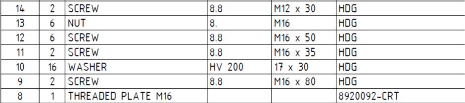
7 Safend 0 C D ( : 5 ) B D ( : 5 ) C ( : 5 ) B ( : 5 ) ( : 5 ) 3 2 Safend SID CP P / RSK750.5BL WSHR RCT. 5x40x5 HOL Ø WSHR ROUND 3x HX NUT M0 MM M SCRW M0 M0x POST SIGM PROFIL HX NUT M MM M WSHR ROUND 7x BOLT M Mx TRNSITION LMNT PROFIL- LFT.3 WSHR ROUND TBRUB 3x24x SCRW M2 M2x CONNCTOR PLT C-POST 40x (SSMBLD) 5 2 HX NUT M20 MM M WSHR ROUND 2x CRRIG BOLT M20 M20x Birsta "Nail" NCHOR TUB 2000 / / INSTLLTION DRWING Released Drawn GLN Copied Design. GLN Stand. Scale Checked ppr. Replaces Replaced by 585, kg Date Drawing no. Rev. T0 PROFIL- LFT Safend 0 SFROD BIRST B L=2000 GRVL L=500 SPHLT PROFIL- 700±20 FOR SYSTM WITH HIGHT 700 mm 720±20 FOR SYSTM WITH HIGHT 720 mm 750±20 FOR SYSTM WITH HIGHT 750 mm TRNSITION ~ 4500 POS. 2, 2., 2.2 & 2.3 PROVIDD S INSTLLTION KIT: HIGHT CC. TO CONNCTING GURD RIL Safend ~ OPTION: PLSTIC COVR MOUNTD ON SIT WITH x MURUTX SCRW 2 M5,5x20. CN B PROVIDD WITH VRIOUS TYP OF RFLX, POINTING TO RIGHT, LFT OR MIDDL X. ~ 295 RGULTIONS prn 37-7 NV 37-4 N ISO 4 (HOT DIP GVNIZING) DDITIONL INFORMTION CC. TO NV 37-4 PRFOMNC LVL: P4 IMPCT SVRITY LVL: B LTRL DISPLCMNT CLSS: D. RDIRCTION ZON: Z DDITIONL INFORMTION CC. TO prn 37-7 PRFORMNC LVL T0 IMPCT SVRITY LVL: B LTRL DISPLCMNT CLSS SO.5 ND T.0 RDIRCTION ZON Z IN PRT LIST STNDS FOR HOT DIP GLVNIZING CCORDING TO SS-N ISO 4 BOLT, SCRWS & NUTS CC. TO N ISO ±20 FOR HIGHT 700 mm 45 ±20 FOR HIGHT 720 mm POS CN B RPLCD WITH GURD RIL POST USD IN CONNCTING SYSTM. RODWY LVL ±20 FOR HIGHT 750 mm 20 5 RODWY LVL GNRL UPDTS GLN FSO No Qty Revision note Date Sign. ppr (2) ±20 mm MX. DVITON FROM VRTICL LIN FOR LL POST RODWY LVL
8 Safend 02 B D ( : 5 ) C ( : 5 ) B ( : 5 ) ( : 5 ) 3 2 Safend SID CP P / RSK750.5BL WSHR RCT. 5x40x5 HOL WSHR ROUND 3x HX NUT M0 MM M SCRW M0 M0x POST SIGM PROFIL HX NUT M MM M WSHR ROUND 7x BOLT M Mx TRNSITION LMNT PROFIL- D0UBL.3 2 WSHR ROUND TBRUB 3x24x SCRW M2 M2x CONNCTOR PLT C-POST 40x (SSMBLD) 5 2 HX NUT M20 MM M WSHR ROUND 2x CRRIG BOLT M20. M20x Birsta "Nail" NCHOR TUB / / INSTLLTION DRWING Released SFROD BIRST B L=2000 GRVL L=500 SPHLT Safend ~ TRNSITION ~ 4500 C OPTION: PLSTIC COVR MOUNTD ON SIT WITH x MURUTX SCRW 2 M5,5x20. HIGHT CC. TO CONNCTING GURD RIL PROFIL- 700±20 FOR SYSTM WITH HIGHT 700 mm 720±20 FOR SYSTM WITH HIGHT 720 mm 750±20 FOR SYSTM WITH HIGHT 750 mm D CN B PROVIDD WITH VRIOUS TYP OF RFLX, POINTING TO RIGHT, LFT OR MIDDL X POS CN B RPLCD WITH GURD RIL POST USD IN CONNCTING SYSTM. 3 ~ 295 RGULTIONS prn 37-7 NV 37-4 N ISO 4 (HOT DIP GVNIZING) DDITIONL INFORMTION CC. TO NV 37-4 PRFOMNC LVL: P4 IMPCT SVRITY LVL: B LTRL DISPLCMNT CLSS: D. RDIRCTION ZON: Z 2 DDITIONL INFORMTION CC. TO prn 37-7 PRFORMNC LVL T0 IMPCT SVRITY LVL: B LTRL DISPLCMNT CLSS SO.5 ND T.0 RDIRCTION ZON Z IN PRT LIST STNDS FOR HOT DIP GLVNIZING CCORDING TO SS-N ISO 4 BOLT, SCRWS & NUTS CC. TO N ISO 048 Drawn GLN Copied Design. GLN Stand. Scale Checked ppr. Replaces Replaced by 35,4 kg Date Drawing no. Rev. T0 PROFIL- DOUBL Safend ± ±20 FOR HIGT 700 mm 40 ±20 FOR HIGT 720 mm 440 ±20 FOR HIGT 750 mm 450 ±20 FOR HIGT 700 mm 45 ±20 FOR HIGT 720 mm 490 ±20 FOR HIGT 750 mm ( : 5 ) POS. 2, 2., 2.2 & 2.3 PROVIDD S INSTLLTION KIT: ,92 GNRL UPDTS GLN FSO No Qty Revision note Date Sign. ppr. RODWY LVL RODWY LVL (2) ±20 mm MX. DVITION FROM VRTICL LIN FOR LL POST

9 Safend 03 B C D B ( : 5 ) C ( : 5 ) D ( : 5 ) ( : 5 ) ( : 5 ) 3 2 Safend SID CP P WSHR RCT. 5x40x WSHR ROUND 2. 3 HX NUT M0 2 3 SCRW M0 3 POST SIGM PROFIL 0 HX NUT M 9 2 WSHR ROUND 8 BOLT M 7 TRNSITION LMNT PROFIL- RIGHT.3 WSHR ROUND TBRUB.2 SCRW M2. CONNCTOR PLT C-POST 40x HX NUT M WSHR ROUND 3 2 CRRIG BOLT M20 2 Birsta "Nail" NCHOR TUB INSTLLTION DRWING Released HOL Ø2 3x24 MM M0 M0x35 MM M 7x34 Mx50 3x24x4 M2x30 MM M20 2x3 M20x / / RSK750.5BL (SSMBLD) / Drawn GLN Copied Design. GLN Stand. Scale Checked ppr. Replaces Replaced by 585, kg Date Drawing no. Rev. T0 PROFIL- RIGHT Safend 03 SFROD BIRST B 250 L=2000 GRVL L=500 SPHLT ~ Safend ~ 8450 TRNSITION ~ 4500 HIGHT CC. TO CONNCTING GURD RIL PROFIL- 700±20 FOR SYSTM WITH HIGHT 700 mm 720±20 FOR SYSTM WITH HIGHT 720 mm 750±20 FOR SYSTM WITH HIGHT 750 mm RGULTIONS prn 37-7 NV 37-4 N ISO 4 (HOT DIP GVNIZING) DDITIONL INFORMTION CC. TO NV 37-4 PRFOMNC LVL: P4 IMPCT SVRITY LVL: B LTRL DISPLCMNT CLSS: D. RDIRCTION ZON: Z DDITIONL INFORMTION CC. TO prn 37-7 PRFORMNC LVL T0 IMPCT SVRITY LVL: B LTRL DISPLCMNT CLSS SO.5 ND T.0 RDIRCTION ZON Z POS. 2, 2., 2.2 & 2.3 PROVIDD S INSTLLTION KIT: IN PRT LIST STNDS FOR HOT DIP GLVNIZING CCORDING TO SS-N ISO 4 BOLT, SCRWS & NUTS CC. TO N ISO 048 OPTION: PLSTIC COVR MOUNTD ON SIT WITH x MURUTX SCRW 2 M5,5x20. CN B PROVIDD WITH VRIOUS TYP OF RFLX, POINTING TO RIGHT, LFT OR MIDDL X ±20 FOR HIGHT 700 mm RODWY LVL ±20 mm MX. DVITON FROM VRTICL LIN FOR LL POST RODWY LVL POS CN B RPLCD WITH GURD RIL POST USD IN CONNCTING SYSTM. 45 ±20 FOR HIGHT 720 mm ±20 FOR HIGHT 750 mm RODWY LVL No GNRL UPDTS GLN Fso Qty Revision note Date Sign. ppr. 9 (2)


10 Safend 04 B D ( : 5 ) C ( : 5 ) B ( : 5 ) ( : 5 ) Safend SID CP P / RSK750.5BL WSHR RCT. 5x40x5 HOL WSHR ROUND 3x HX NUT M0 MM M SCRW M0 M0x POST SIGM PROFIL HX NUT M MM M WSHR ROUND 7x BOLT M Mx TRNSITION LMNT PROFIL-B LFT.3 WSHR ROUND TBRUB 3x24x SCRW M2 M2x CONNCTOR PLT C-POST 40x (SSMBLD) 5 2 HX NUT M20 MM M WSHR ROUND 2x CRRIG BOLT M20. M20x Birsta "Nail" NCHOR TUB 2000 / / INSTLLTION DRWING Released Drawn GLN Copied Design. GLN Stand. Scale Checked ppr. Replaces Replaced by Birsta SFO Safend T0 58,7 kg Date PROFIL-B LFT Drawing no. Safend 04 Rev. SFROD BIRST B ±0-20 L=2000 GRVL L=500 SPHLT Safend ~ 8450 TRNSITION ~ 4500 C HIGHT CC. TO CONNCTING GURD RIL 7 ~ 295 RGULTIONS prn 37-7 NV 37-4 N ISO 4 (HOT DIP GVNIZING) DDITIONL INFORMTION CC. TO NV 37-4 PRFOMNC LVL: P4 IMPCT SVRITY LVL: B LTRL DISPLCMNT CLSS: D. RDIRCTION ZON: Z 2 DDITIONL INFORMTION CC. TO prn 37-7 PRFORMNC LVL T0 IMPCT SVRITY LVL: B LTRL DISPLCMNT CLSS SO.5 ND T.0 RDIRCTION ZON Z RODWY LVL RODWY LVL OPTION: PLSTIC COVR MOUNTD ON SIT WITH x MURUTX SCRW 2 M5,5x20. CN B PROVIDD WITH VRIOUS TYP OF RFLX, POINTING TO RIGHT, LFT OR MIDDL X.. IN PRT LIST STNDS FOR HOT DIP GLVNIZING CCORDING TO SS-N ISO 4 BOLT, SCRWS & NUTS CC. TO N ISO ±20 FOR HIGT 700 mm 45 ±20 FOR HIGT 720 mm 490 ±20 FOR HIGT 750 mm POS CN B RPLCD WITH GURD RIL POST USD IN CONNCTING SYSTM. 3 No PROFIL-B 700±20 FOR SYSTM WITH HIGHT 700 mm 720±20 FOR SYSTM WITH HIGHT 720 mm 750±20 FOR SYSTM WITH HIGHT 750 mm D GNRL UPDTS GLN FSO Qty Revision note Date Sign. ppr ( : 5 ) POS. 2, 2., 2.2 & 2.3 PROVIDD S INSTLLTION KIT: (2) ±20 MX. DVITION FROM VRTICL LIN FOR LL POST RODWY LVL
11 Safend 05 D C ( : 5 ) B D ( : 5 ) C ( : 5 ) B ( : 5 ) ( : 5 ) 3 2 Safend SID CP P / RSK750.5BL WSHR RCT. 5x40x5 HOL WSHR ROUND 3x HX NUT M0 MM M SCRW M0 M0x POST SIGM PROFIL HX NUT M MM M WSHR ROUND 7x BOLT M Mx TRNSITION LMNT PROFIL-B DOUBL.3 2 WSHR ROUND TBRUB 3x24x SCRW M2 M2x CONNCTOR PLT C-POST 40x (SSMBLD) 5 2 HX NUT M20 MM M WSHR ROUND 2x CRRIG BOLT M20. M20x Birsta "Nail" NCHOR TUB 2000 / / INSTLLTION DRWING Released SFROD BIRST B ±20 FOR HIGT 700 mm 45 ±20 FOR HIGT 720 mm 490 ±20 FOR HIGT 750 mm L=2000 GRVL L=500 SPHLT Safend ~ OPTION: PLSTIC COVR MOUNTD ON SIT WITH x MURUTX SCRW 2 M5,5x20. CN B PROVIDD WITH VRIOUS TYP OF RFLX, POINTING TO RIGHT, LFT OR MIDDL X. TRNSITION ~ 4500 PROFIL-B 700±20 FOR SYSTM WITH HIGHT 700 mm 720±20 FOR SYSTM WITH HIGHT 720 mm 750±20 FOR SYSTM WITH HIGHT 750 mm 2 HIGHT CC. TO CONNCTING GURD RIL RODWY LVL ~ 295 RGULTIONS prn 37-7 NV 37-4 N ISO 4 (HOT DIP GVNIZING) DDITIONL INFORMTION CC. TO NV 37-4 PRFOMNC LVL: P4 IMPCT SVRITY LVL: B LTRL DISPLCMNT CLSS: D. RDIRCTION ZON: Z DDITIONL INFORMTION CC. TO prn 37-7 PRFORMNC LVL T0 IMPCT SVRITY LVL: B LTRL DISPLCMNT CLSS SO.5 ND T.0 RDIRCTION ZON Z3 RODWY LVL POS. 2, 2., 2.2 & 2.3 PROVIDD S INSTLLTION KIT: POS CN B RPLCD WITH GURD RIL POST USD IN CONNCTING SYSTM. GNRL UPDTS GLN FSO No Qty Revision note Date Sign. ppr IN PRT LIST STNDS FOR HOT DIP GLVNIZING CCORDING TO SS-N ISO 4 BOLT, SCRWS & NUTS CC. TO N ISO 048 Design. Drawn Copied Stand. GLN GLN FSO FSO Checked ppr. Scale Replaces Replaced by T0 PROFIL-B DOUBL 33,4 kg Safend 05 Drawing no. Date Rev. ±20 mm MX DVITION FROM VRTICL LIN FOR LL POST RODWY LVL 390 ±20 FOR HIGT 700 mm 40 ±20 FOR HIGT 720 mm 440 ±20 FOR HIGT 750 mm (2)

12 Safend 0 B C D B ( : 5 ) C ( : 5 ) D ( : 5 ) (:5) ( : 5 ) 3 2 Safend SID CP P / RSK750.5BL WSHR RCT. 5x40x5 HOL Ø WSHR ROUND 3x HX NUT M0 MM M SCRW M0 M0x POST SIGM PROFIL HX NUT M MM M WSHR ROUND 7x BOLT M Mx TRNSITION LMNT PROFIL-B RIGHT.3 WSHR ROUND TBRUB 3x24x SCRW M2 M2x CONNCTOR PLT C-POST 40x (SSMBLD) 5 2 HX NUT M20 MM M WSHR ROUND 2x CRRIG BOLT M20. M20x Birsta "NIL" NCHOR TUB 2000 / / INSTLLTION DRWING Released SFROD BIRST B RODWY LVL ±20 MW. DVITION FROM VRTICL LIN FOR LL POST RODWY LVL HIGHT CC. TO CONNCTING GURD RIL PROFIL-B 700±20 FOR SYSTM WITH HIGHT 700 mm 720±20 FOR SYSTM WITH HIGHT 720 mm 750±20 FOR SYSTM WITH HIGHT 750 mm RGULTIONS prn 37-7 NV 37-4 N ISO 4 (HOT DIP GVNIZING) DDITIONL INFORMTION CC. TO NV 37-4 PRFOMNC LVL: P4 IMPCT SVRITY LVL: B LTRL DISPLCMNT CLSS: D. RDIRCTION ZON: Z DDITIONL INFORMTION CC. TO prn 37-7 PRFORMNC LVL T0 IMPCT SVRITY LVL: B LTRL DISPLCMNT CLSS SO.5 ND T.0 RDIRCTION ZON Z POS. 2, 2., 2.2 & 2.3 PROVIDD S INSTLLTION KIT: RODWY LVL POS CN B RPLCD WITH GURD RIL POST USD IN CONNCTING SYSTM.. IN PRT LIST STNDS FOR HOT DIP GLVNIZING CCORDING TO SS-N ISO 4 BOLT, SCRWS & NUTS CC. TO N ISO 048 OPTION: PLSTIC COVR MOUNTD ON SIT WITH x MURUTX SCRW 2 M5,5x20. CN B PROVIDD WITH VRIOUS TYP OF RFLX, POINTING TO RIGHT, LFT OR MIDDL X. No GNRL UPDTS GLN FSO Qty Revision note Date Sign. ppr. Design. Drawn Copied Stand. GLN GLN FSO FSO Checked ppr. Scale Replaces Replaced by T0 PROFIL-B RIGHT 58,0 kg Safend 0 Drawing no. Date Rev. 250 L=2000 GRVL L=500 SPHLT ~ 295 Safend ~ 8450 TRNSITION ~ ± ±20 FOR HIGT 700 mm 45 ±20 FOR HIGT 720 mm 490 ±20 FOR HIGT 750 mm (2)
SINGLE SIDED SAFETY BARRIER ON GROUND H2-W4-A (3n35975)
") SINGLE SIDED SAFETY BARRIER ON GROUND H2-W4-A (3n397) Performance Containment level Acceleration Severity Index ASI Working width Extreme lateral position of the vehicle Dynamic deflection H2 A W4 (1.30
SINGLE SIDED SAFETY BARRIER ON GROUND H2-W4-A (3n397) Performance Containment level Acceleration Severity Index ASI Working width Extreme lateral position of the vehicle Dynamic deflection H2 A W4 (1.30
KROFTMAN CONTAINER SHELTER TC812
 KROFTMAN CONTAINER SHELTER CONTENT FRAME P82-FR 82-0 82-02 82-03 82-0 82-05 82-06 82-07 parts list frame part numbers main frame base plan, frame plan available hight inside detail 0 detail 02, 03 Roof
End Terminals Installation and Repair Manual SMAT2 SMAT4
 End Terminals Installation and Repair Manual SMAT2 SMAT4 Industry A.M.S. s.r.l. Via Dante Giacosa snc zona ASI sud 81025 Marcianise (CE) Italy Phone: +39 0823 821 560 info@amssrl.com Rev. 04/08/2016 INDEX
Overhead transmission lines Spacers
 = SVENSKA KRAFTNÄT SWEDISH NATIONAL GRID UNIT, BUSINESS AREA AEL, Asset Management Lines OUR REFERENCE TR05-08E DATE 2016-06-09 CONSU12TATIONS TECHNICAL GUIDELINE REVISION 3 APPROVED Overhead transmission
Midwest Roadside Safety Facility
 24" 609 Asphalt Impact 3/1 [1300] upstream from upstream end of permanent barrier B 166'-10 1/1 50853 25 Plan View 3/1 1300 3 813 Free-Standing Kansas Barriers Kansas Barrier With 2 Asphalt Stakes Per
TEKNISK RIKTLINJE TR05-10E
 Notes Change notes Date 1 (A) Revision of standards and new template 09 / 07 2010 2 Template changed.clause. 10.5.1.4 support clamp inserted. Clause 10.5.4.2 creepage text revised. Clause 10.6.7 Dry inserted
Three Phase Flat Motors Three Phase Saw Arbor Motors. for sawing, milling, routing of wood, plastics and metal. type of protection IP 54
 Thr Phs Flt Motors Thr Phs Sw Arbor Motors for swing, milling, routing of wood, plstics nd mtl of protction IP 54 Thr phs flt motors with br of protction IP 54 Thr phs flt motors of protction IP 55 (possibl
Overhead transmission lines Tension clamp
 SVENSKA KRAFTNÄT T~ SWEDISH NATIONAL GRID UNIT, BUSINESS AREA AFL, Asset Management Lines OUR REFERENCE TR05-06E DATE 2016-06-09 CONSULTÅTIONS m /j(j TECHNICAL GUIDELINE REVISION 3 Td APPROVED Overhead
TO BE USED FOR MAINTENANCE MICHIGAN DEPARTMENT OF TRANSPORTATION. 2 3/16" x 2 3/16" x 10 Ga. 12" 15.5" 1 1/2" x 1 1/2" x 12 Ga.
 2 3/16" x 2 3/16" x 10 Ga. TOP VIEW 18" 1" 7/16" Hole 1 1/2" x 1 1/2" x 12 Ga. two sides only steel tubing 1 1/2" x 1 1/2" x 12 Ga. @ 18" long steel angle 15.5" 12" TRAFFIC 3/8" Hex head grade 5 steel
Installation and Maintenance Manual. End Terminals
 End Terminals Rev. 01 of the 19/3/2015 1 1.GENERAL 1.1 Foreword. The following document represents the SMA (Safety Modular Absorber) Installation and Maintenance Manual, developed from the Company Industry
1.1 EP-1 PUMP WITHOUT TIMER
 LUBRICATION SYSTMS LCTRIC PUMPS SCTION 1. LCTRIC PUMPS 1.1 P-1 PUMP WITHOUT TIMR APPLICATIONS Hydraulic hammer lubrication or for use in systems with pre-existing or remote timers. SPCIFICATIONS Voltage:
Lincoln Under-cabinet Light Installation Instructions
 Lincoln Under-cbinet Light Instlltion Instructions #1500178 Rev A Congrtultions on your new Lincoln Under-cbinet Light! Whether purchsed for its significnt energy svings nd efficiency, lower lifetime costs,
SECTION A-A
 40.08 D 8 6 5 4 3 2 1 WRNING: IF THERE RE NY DISCREPNCIES ETWEEN THE CD FILE ND THE DRWING, THE DRWING WILL TKE PRECEDENCE. IF IN DOUT, SK. D C 51.1 48 20.25 18 C 23.68 15.12 NOTE: DRWER UNIT NOT INCLUDED,
BEARINGS Ball & Socket Joints - DIN Left & Right (d 2 b )Handed : M5 - M16. Nut Supplied (ISO 4032) d1 d2 d2b d3 L a e l4 l2 L3 R
Handed : M5 - M16. Nut Supplied (ISO 4032) d1 d2 d2b d3 L a e l4 l2 L3 R") l4 RAS l3 l2 d 2 Push/Pull SW (A/F) Bll & Sockt Joints DIN 7102 Lft & Right (d 2 b )Hndd : M 15 Front to Bck d 1 R 15 15 15 L Sid to Sid Nut Supplid (ISO ) RAS Typ: RIGHT HAND THREADED Stl (Zinc Pssivtd)
l4 RAS l3 l2 d 2 Push/Pull SW (A/F) Bll & Sockt Joints DIN 7102 Lft & Right (d 2 b )Hndd : M 15 Front to Bck d 1 R 15 15 15 L Sid to Sid Nut Supplid (ISO ) RAS Typ: RIGHT HAND THREADED Stl (Zinc Pssivtd)
WARNING: IF THERE ARE ANY DISCREPANCIES BETWEEN THE CAD FILE AND THE DRAWING, THE DRAWING WILL TAKE PRECEDENCE. IF IN DOUBT, ASK.
 28.48 DJUSTLE 5.64 19.78 DJUSTLE D 8 7 6 5 4 3 2 1 20.37 WRNING: IF THERE RE NY DISCREPNCIES ETWEEN THE CD FILE ND THE DRWING, THE DRWING WILL TKE PRECEDENCE. IF IN DOUT, SK. D 51.80 48.00 9.57 C C 18.00
2/2 Solenoid Operated Seat Valve, ISO Size 03
 2/2 Solenoid Operted Set Vlve, ISO Size 03 Q mx = 40 l/min (11 gpm), p mx = 315 r (4500 psi) Sndwich design, idirectionl lek-proof shutoff, direct cting, electriclly operted 1 Description 2 echnicl dt
SECTION 14: AERIAL LIFT PROGRAM
 SECTION 14: AERIAL LIFT PROGRAM Fisher Auto Parts is committed to promoting a safe and healthy environment for all employees and customers. Protection from accidental loss of any resources, especially
제품문의 : SR Tech KALLER GAS SPRING 공식공급업체 100 ( xStroke ) K 500 x 25 mm Initial Force 500 dan 80 ( xStroke )
 K 500 x 25 mm Initial Force 500 dan 80 ( xStroke )") www.rtech.o.kr 제품문의 : R Th 01-966-7017 KAER GA PRING 공식공급업체 Ovrviw - 00 F INIT < 70 3 3 13 ( 8 + 2xtrok ) TU 00 x 2 mm 100 ( 0 + 2xtrok ) K 00 x 2 mm 82 ( 32 + trok ) K 00 x 2 mm Initil For 00 dn Initil
www.rtech.o.kr 제품문의 : R Th 01-966-7017 KAER GA PRING 공식공급업체 Ovrviw - 00 F INIT < 70 3 3 13 ( 8 + 2xtrok ) TU 00 x 2 mm 100 ( 0 + 2xtrok ) K 00 x 2 mm 82 ( 32 + trok ) K 00 x 2 mm Initil For 00 dn Initil
FS II - Mounting Instruction. 1 General 2. 2 Pile driving (Ramming) 3. 3 Mounting individual assemblies 4. 4 Components list 5
 3. 3 Mounting individual assemblies 4. 4 Components list 5") FS II Mounting Instruction CONTENTS Page 1 General 2 2 Pile driving (Ramming) 3 3 Mounting individual assemblies 4 4 Components list 5 5 Torque specifications 9 6 Module mounting 9 7 Cable mounting 10
FS II Mounting Instruction CONTENTS Page 1 General 2 2 Pile driving (Ramming) 3 3 Mounting individual assemblies 4 4 Components list 5 5 Torque specifications 9 6 Module mounting 9 7 Cable mounting 10
20T Low Headroom Hoist Date TNC 20/4 LHR DRG /02/ / 1. If In Doubt Ask REVISION HISTORY. Part Number. 890kg Weight D01-AHT35 REV0
 REVISION HISTORY REV. DTE PPROVED D-HT REV Scale not to scale Designed y Drawn y Checked y pproved y Surname T. Mikolajewski T. Mikolajewski. itken Title of Project Title of Part / Linear up to, over up
LIFTING DEVICES AND LIFTING EQUIPMENT - USE AT INOVYN
 INSTRUCTIONS 1(9) LIFTING DEVICES AND LIFTING EQUIPMENT - USE AT INOVYN Table of contents 1. Lifting devices and lifting equipment - General - Inspection and risk assessment - Equipment requirements -
A Assembly Instructions Trampoline Piccolo Art with Special Installation Frame
 A Assembly Instructions Trampoline Piccolo Art. 20.02.116 with Special Installation Frame Operator: Location: T:\PLAY\Play Installation Instructions\Installation Instructions 2012-2013\20_02_116-01-en-000.doc
Recover Light Vehicles Using Advanced Winching Techniques
 IMIRR05 Recover Light Vehicles Using Advanced Winching Techniques Overview This standard is about recovering vehicles using advanced winching techniques. For the purpose of this standard light vehicles
N2-GEN. TL SERIES Nitrogen Generators. Arc Suppression System. Transmission Line Pressurization. South-Tek
 TL SERIES Nitrogen Generators Transmission Line Pressurization N2-GEN rc Suppression System www.southteksystems.com commercialsales@southteksystems.com 888.526.6284 South-Tek Systems 2 N 2 -GEN rc Suppression
A Assembly Instructions Space Capsule, Art-No
 A Assembly Instructions Space Capsule, Art-No. 20.01.020 T:\PLAY\Play Installation Instructions\Installation Instructions 2012-2013\20_01_020-01-en-003.doc - 1 - Revision history Revision 0 2004-06-22
Service - Safety Manual
 Service - Safety Manual Mounting and maintenance instructions Linear Units LT50 series Code Unit Serial number Date by Linear Units LT50 series Table of contents 1 Safety 3 1.1 Significance of the manual
WORKING SAFELY NEXT TO WEST MIDLANDS METRO
 WORKING SAFELY NEXT TO WEST MIDLANDS METRO GUIDELINES FOR BUSINESSES, CONTRACTORS, EVENT ORGANISERS & OTHERS WORKING ON OR NEAR TO WEST MIDLANDS METRO. If you own, occupy a building or other assets near
ILLUMINATING EVERYNICHE MOMRA POLES
 ILLUMINTING EVERYNICHE MOMR POLES d ø 2 ROWS OF FIXING NUTS ** OVERLP H CONICL SHFT MOMR Poles The MOMR poles have International standard performance ensuring high functioning quality, as well as great
Driver Fatally Injured by Fall from Truck Date of Incident: March 5, 2007 Type of Incident: Fatality
 Driver Fatally Injured by Fall from Truck Date of Incident: March 5, 2007 Type of Incident: Fatality TABLE OF CONTENTS PAGE NUMBER SECTION 1.0 DATE AND TIME OF INCIDENT 3 SECTION 2.0 NAME & ADDRESS OF
ZONE 09FENCING SECTION
 ZONE FENCING De-fence is designed to comply with AS4024.1 when used as machinery guarding. Alternatively, its flexible design lends itself to many applications, including forklift separation and workplace
Screwdrivers. Ergonomically designed handles. Greater torque. Slip-proof grip. Threecomponent. handle a. TBI Screwdrivers
 Screwdrivers TBI Screwdrivers R Screwdrivers NI Screwdrivers VE Screwdrivers VE TBI Screwdrivers Bits Impct screwdrivers Other ccessories Ergonomiclly designed hndles The superior qulity of mterils used
Midwest Roadside Safety Facility
 60960 10 9 7* 6* 5* 4* 3* 2 1 Elevation View Bridge Pit 3214.3 6197.6 A 304. A 1300.2 25 TRAFFIC SIDE Sections 1 and 10 only anchored into concrete pad with 9 A36 25.4 x 394mm long unthreaded steel rods
0 /28 Standard /-24 NEW XL-TILT STANDARD RANGE 112/350. Min 49. TELESCOPIC 70/80 mm. Min 422 STANDARD RANGE STANDARD RANGE 262/
 2 28 144 28 132 2 507 144 400 2 775 135 0 12 0 /28 Standard 36 - +12 /-24 NEW XL-TILT 24 24 12 2/350 STNDRD RNGE Min 49 142 0 TELESCOPIC /80 mm 132 0 490 103 TELESCOPIC STROKE 50/100 45 95 81 65 262/600
HARDWARE WIRE BALUSTRADING FITTINGS MARINE AND ARCHITECTURAL.
 MRIN N RHITTURL HRWR WIR LUSTRING FITTINGS OPYRIGHT Y JMS GLN PTY LT *OL: Normal stocked items, ITLI: Please contact our sales team for availabilty and price 1 WIR LUSTRING FITTINGS STINLSS MRIN & RHITTUR
CAM INDEX PAGE DATE DESCRIPTION
 CM INX 8/24/7 PG T SCRIPTION C-1 8/24/7 Cam Index C-2 6/27/7 erial Cam Specifications C-3 3/23/4 erial Cam Specifications C-4 6/9/4 Standard erial Cam nvelope C-5 8/24/7 Performance Calculation, ie Mount
Accessories. Inlet nozzles 550. Guard grilles 553. Lead connections, capacitors 558. Terminal boxes, air filters 562
 Accessories Generl informtion Inlet nozzles 550 Gurd grilles 553 Led connections, cpcitors 558 Terminl boxes, ir filters 562 Speed setting, motor protection switch, third-prty ccessories 564 Technology
Kenstan. Volume 5. Knob Line of Locks. Introduction. Cam Locks. Drawer/Door Locks. Snap Bolt Lock. Plunger Lock PL40.
 Volume 5 a t a l o g L O K O M P N Y of Locks 2 S V Introduction 1 am Locks 2 3 rawer/oor Locks 4 Snap olt Lock 5 PL40 6 PL45 7 PL50 8 L O K O M P N Y List and ata Sheet Introduction 1 of Locks Standard
SHEET 1 OF 6
 REVISIONS REV DESCRIPTION CHG.NO. PP'D DTE SENSOR WELD NECK MOUNTING FLNGE & WELD FTG. (FCTORY WELDED) VILBLE IN SME B16.5 RF & RTJ, ND EN 1092-1 RF. REFER TO TBLE 1 ON SHEET 2 OR FOR S ND DIMENSIONS NEW
DUO-LOCK. Double clamping equipment DUO-LOCK HD. Set of hard jaws. Set of soft jaws. Conversion kit for single clamping. THD tower DUO-LOCK HD
 Double clamping equipment DUO-LOK HD Pag. 10.3 DUO-LOK base equipment DUO-LOK HD with wrench 10 Set of hard jaws Pag. 10.3 Set of soft jaws Pag. 10.3 onversion kit for single clamping Pag. 10.9 THD tower
VELAN COMPANY PROFILE
 VL-GPV-27 VLN COMPNY PROFIL Velan is one of the world's leading manufacturers of industrial steel valves, supplying gate, globe, check, ball, butterfly and knife gate valves for critical applications in
00083FAB-DC DRAWN BY DATE CHK SCALE SIZE
 D0D/6 THIS COPY IS PROVIDED ON RESTRICTED SIS ND IS NOT TO E USED IN NY WY DETRIMENTL TO THE INTERESTS OF PNDUIT CORP. 0 5/4/8 SPLIT SIDE PNEL JGC TOP CP CURVED PERFORTED SINGLE HINGE DOOR SPLIT SIDE PNEL
Spring hangers, spring supports
 Spring hangers, spring supports 2 spring Spring hangers, supports PRODUCT 2 GROUP Spring hangers, spring supports Contents Page Field of application...2.1 Overview of spring hangers and spring supports...2.3
A Assembly Instructions Trampoline 2012 Art
 A Assembly Instructions Trampoline 2012 Art. 20.02.108 Operator: Location: M:\Spogg\Englisch\20_02_108-01-en-001.doc\20-02-108-eng-01-001.doc - 1 - Revision history Revision 0 2012-03-21 Revision 1 2012-08-02
STANDARD CONSTRUCTION DETAILS STORM DRAINAGE REVISED - MAY 2017 DEPARTMENT OF ENGINEERING
 STNDRD CONSTRUCTION DETILS STORM DRINGE REVISED - MY 2017 DEPRTMENT OF ENGINEERING GENERL NOTES CONCRETE,SPHLT STREET REPIR,PIPE EDDING UTILITY SUPPORT,WTER MIN LOWERING,CONCRETE COLLR TYPE "" STORM SEWER
Section VIII Hydraulic Tooling
 Section VIII Hydraulic Tooling MSTRLIN CYLINR CCSSORY MTING CHRT Masterline Knuckle Masterline Clevis racket Masterline RS Masterline lignment Coupler KN-1 C-1 1/2 x 1 7/8-RS SC-5 KN-2 C-2 1/2 x 2 5/8-RS
GUIDELINES FOR OPERATING, METERING AND PROTECTIVE RELAYING FOR. NET METERED SYSTEMS UP TO 50 kw AND BELOW 750 VOLTS
 GUIDELINES FOR OPERATING, METERING AND PROTECTIVE RELAYING FOR NET METERED SYSTEMS UP TO 50 kw AND BELOW 750 VOLTS 1. INTRODUCTION... 3 1.1 POLICY ON CUSTOMER GENERATION.... 3 1.2 GENERATION SOURCES AND
Installation Instruction
 CIVCON MNIFOLD INSTLLTION MNUL REVISION 5/9/05 PETROLEUM MNIFOLD for TNK TRUCKS Installation Instruction Unit of Knappco, Inc. Phone: 86-74-6600 Fax: 86-74-06 CIVCON MNIFOLD INSTLLTION MNUL REVISION 5/9/05
Installation, Operation, and Maintenance Manual
 Intelligent Flow Measurement Your Sole Source for Badger Differential Producers Worldwide 6 Blackstone Valley Place, Lincoln RI 02865-1162 Ph: 401 334 1170 Fx: 401 334 1173 Em: solutions@wyattflow. Installation,
MANUAL ABOVE GROUND FUEL TANKS FOT HEATING MODELS MZPEB 1200 MZPEB 2500 MZPEB 3300
 MANUAL ABOVE GROUND FUEL TANKS FOT HEATING MODELS MZPEB 1200 MZPEB 2500 MZPEB 3300 PICTURE SUBJECT PAGE 2 Storage, transport, installation procedures, warranty above ground fuel tanks Watertight connection
Detroit Speed, Inc. Subframe Connector Kit Mustang P/N #
 Detroit Speed, Inc. Subframe Connector Kit 1964.5-1968 Mustang P/N # 010105 Item Component Quantity 1 Subframe Connector 2 2 Front Frame Rail Doubler LH 1 3 Front Frame Rail Doubler RH 1 4 Front Frame
NET-ACCESS S TYPE VED READY CABINET 600mm WIDE X 1200mm DEEP FAMILY 12V343ST-DC VED TOP CAP FRONT PERFORATED SINGLE HINGE DOOR SPLIT SIDE PANEL
 THIS COPY IS PROVIDED ON RESTRICTED SIS ND IS NOT TO E USED IN NY WY DETRIMENTL TO THE INTERESTS OF PNDUIT CORP. PNEL VED TOP CP PERFORTED SINGLE HINGE PNEL SOLID RER NET-CCESS S TYPE VED REDY CINET 600mm
Quadro Outdoor T2 S/D
 Quadro Outdoor T2 S/D Our solution for high demands outdoor operation no columns or any other barrier in the area of the doors Made in Germany Areas of application: private houses, residential buildings,
Arcadia ssembly Instructions. 501x363x242cm / 16 5"Lx11 103/4"x7 111/4"
 A ssemly Instructions Arcdi 5000 English_71087 501x36342cm / 16 5"Lx11 103/4"x7 111/4" Compny informtion: Plrm Americs Inc. 9735 Commerce Prkwy Kutztown, PA, USA Service Center: Toll Free: (877) 627-8476
UNEQUAL FLANGE RACK ACCESSORIES
 CUSTOM CBINETS & RCKS Products for Custom Installation Solutions www.custcab.com UNEQUL FLNGE RCK CCESSORIES Custom Cabinets & Racks offers a large range of accessories to custom tailor UEF equipment racks
Fertilizer Spreader FSP500, FSP700 & FSP P Parts Manual. Copyright 2016 Printed 03/22/16
 Fertilizer Spreader FSP500, FSP700 & FSP1000 24974 309-065P Parts Manual Read the Operator's Manual entirely. When you see this symbol, the subsequent instructions and warnings are serious - follow without
M REV. H JUNE 2015 OPERATION MANUAL MTB-25 & MTB-30
 M-00-40 REV. H JUNE 2015 OPERATION MANUAL MTB-25 & MTB-30 To find maintenance & parts information for your MTB-25 & MTB-30 Liftgate, go to www. maxonlift.com. Click the PRODUCTS, MTB- 25 & MTB-30 buttons.
PROCEDURE. Operative Date: 22/12/2016 Department: HSEC. Revision: Author: D Steel CONTENTS
 Title: Cranes - Inspection and Maintenance PROCEDURE Procedure No: P314.422 Issue: 1 Revision: 0 Operative Date: 22/12/2016 Department: HSEC Sect./Classification: Safety / Gear & Equipment Author: D Steel
Appendix C. 5% Design Plan and Profile Drawings/ Additional Design Information. South Oak Cliff Corridor Blue Line Extension
 Appendix C 5% Design Plan and Profile Drawings/ Additional Design Information The 5% plan and profile drawings were provided in a separate volume with the Draft Local EA and have not changed. Hard copies
TMH 15000/5. 15TE / 5F Air Hoist 1:5 DRG /11/ ,5 313,5 1 / 1. If In Doubt Ask REVISION HISTORY. Part Number.
 D-AH REV ITEM QTY PART NUMBER DRG 7 DRG 7 TMH PARTS LIST DESCRIPTION Top Block Bottom Block Air Hoist (with Lever Plate DRG 7 ) REV. REVISION HISTORY REV. DATE APPROVED : Scale Designed By Drawn By Checked
HIGH MAST LIGHTING. Lowering Devices
 HIGH MST LIGHTING Lowering Devices 6 I NFRSTRUCTUR Product Catalog Lowering Devices Since 970, Holophane has been the most reliable supplier of high mast systems in the world. Holophane has the largest
Installation Guide. Marking and Inspection Gauge. Marking Gauge. Inspection Gauge E 1. Marking and inspection gauges are combined into one gauge.
 Marking and Inspection Gauge Marking and inspection gauges are combined into one gauge. Marking Gauge The gauge has a pin and a slot for marking along the centerline. Position the pin with the end of the
53A SPECIFICATION SECTION NO. (COVER ONLY ONE SECTION WITH. OF SPECIFICATION SHEET, ONLY NO. (Type, size, model number, etc.)
") TRANSMITTAL OF SHOP DRAWINGS, EQUIPMENT DATA, MATERIAL SAMPLES, OR MANUFACTURER'S CERTIFICATES OF COMPLIANCE FOR APPROVAL (READ INSTRUCTION ON THE REVERSE SIDE PRIOR TO INITIATING THIS FORM) 1. REQUEST
TRANSMITTAL OF SHOP DRAWINGS, EQUIPMENT DATA, MATERIAL SAMPLES, OR MANUFACTURER'S CERTIFICATES OF COMPLIANCE FOR APPROVAL (READ INSTRUCTION ON THE REVERSE SIDE PRIOR TO INITIATING THIS FORM) 1. REQUEST
SAFETY DIRECTIVE 2.0 DEPARTMENTS AFFECTED
 SAFETY DIRECTIVE Title: Ladders Issuing Department: Town Manager s Safety Office Effective Date: July 1, 2014 Approved: Gilbert Davidson, Town Manager Type of Action: New 1.0 PURPOSE This procedure has
SE Encore Multimount Worm Gear Speed Reducers
 S ncore Worm ear Speed Reducers VILL IN 24 HOURS! Winuard lack poxy Coating System Quill Input daptor Solid Output Shaft(s) (Standard Diameter) Hollow Output Shafts (Max Standard ore) ushing Kits ase Kits
A Assembly Instructions for Trampoline 2000, Art With Installation Frame, Art
 A Assembly Instructions for Trampoline 2000, Art. 20.02.125 With Installation Frame, Art. 20.02.123 Or Special Installation Frame, Art. Nr. 20.02.128 Operator: Location: \\Fileserver\text\PLAY\Play Installation
Existing 400A Circuit Breaker For B Secondary Chill Water Pump. Existing Single 2.5 Conduit. Reuse As Much As Practical
 New A Secondary Chill / 60V /36A Fused Disconnect For A Secondary Chill and Flex New B Secondary Chill / 60V / 36A B Secondary Chill Single 2.5 Conduit. Install New Additional 2.5 R.S.G. Conduit From 00A
Isolation Valves. phone fax
 Isolation Valves 2 TL OF ONTNTS Page 2 Isolation Valves General Information Page 3 Page 4 Page 5 Why choose an Isolation Valve and ommon pplications Isolation Valve Selection Guide 038T Series Isolation
FPD220 meter 2 di Dual-chamber orifice fitting with double isolation
 Data sheet DS/FPD220 EN FPD220 meter 2 di Dual-chamber orifice fitting with double isolation Measurement made easy Safety by design Double isolation with visible proofing mechanism meets HSG253 Category
SIDE DETAIL ELEVATION DETAIL JCM VIVA VISIO SYSTEM PRODUCT DATA -
 * UCP REQUIRED IF SYSTEM DOES NOT HVE HNDRIL OPTIONL CPS ) SS 'U' CP ) SS Ø" CP 3) SS Ø" LED CP ) Ø " OR Ø" SS HNDRIL ) Ø" WOOD HNDRIL CHERRY WOOD " GP (NOM) RED OK WHITE OK MPLE WOOD 3) Ø " LED iril 3'7"
Tank Top Mounted Suction & Return Line Filters
 Suction Tank Top Mounted Suction & Return Line Filters Max 13 l/min - 1 bar Return Series Global Filtration Technology TYPICL PPLICTIONS OPRTIONL DIGRM Mobile equipment with both open and closed hydraulic
Date No ST Suspensions is a brand of KW automotive North America, Inc. - KW automotive North America, Inc.
 Page 1 INSTLLTION INSTRUCTIONS Before you start to install, please read the following instructions carefully: - The suspension components must match the suspension application specifications (springs and
Lower Extremities USER MANUAL RLSHW100. Stealth s User Manual and Maintenance Guide for Residual Limb Support
 Lower Extremities USER MANUAL RLSHW100 Stealth s User Manual and Maintenance Guide for Residual Limb Support Customer Satisfaction 1.0 Stealth Products strives for 100% customer satisfaction. Your complete
Assembly instruction Cheops-Pyramid Midi. Art B to be dug in
 HUCK GmbH Dillerberg 3 35614 Asslar-Berghausen A Assembly instruction Cheops-Pyramid Midi Art. 4643-2B to be dug in Operator: Location: \\Fileserver\text\PLAY\Play Installation Instructions\Installation
REMOVABLE MOUNT INSTALLATION FOR TRUCK BODIES For truck bodies only, not for trailers. Recommended for use with Dump Beds. See Drawing F.
 REMOVBLE MOUNT INSTLLTION FOR TRUCK BODIES For truck bodies only, not for trailers. Recommended for use with Dump Beds. See Drawing 102468F. IMPORTNT. Safe and reliable operation of Donkey mounting kits
Fertilizer Spreader PFS4000, PFS5060 & PFS P Parts Manual. Copyright 2017 Printed 02/03/17
 Fertilizer Spreader PFS4000, PFS5060 & PFS8010 30752 309-124P Parts Manual Read the Operator's Manual entirely. When you see this symbol, the subsequent instructions and warnings are serious - follow without
Amendment Sheet. Code : ADB-FR Date : Superceded : nil REFRIGERANT CIRCUIT DIAGRAM
 mendment Sheet Code : DB-FR-007-0001 Date : 18-0-008 Superceded : nil REFRIGERNT CIRCUIT DIGRM GENERL DT HETPUMP (R) NOMINL COOLING CPCITY NOMINL HETING CPCITY NOMINL TOTL INPUT POER (COOLING) NOMINL TOTL
THIS COPY IS PROVIDED ON A RESTRICTED BASIS AND IS NOT TO BE USED IN ANY WAY DETRIMENTAL TO THE INTERESTS OF PANDUIT CORP.
 THIS COPY IS PROVIDED ON RESTRICTED SIS ND IS NOT TO E USED IN NY WY DETRIMENTL TO THE INTERESTS OF PNDUIT CORP. SIDE PNEL 2 TOP CP PERFORTED SINGLE HINGE KNOCK-OUTS FOR PDU POWER CORD SIDE PNEL RER PERFORTED
Installation guide. Mb 3101, Mb Drive systems. Part number: 2910 en / p
 Installation guide Mb 30, Mb 000 Drive systems Part number: 90 en - 07.08 / p INSTALLATION - Mb 30, Mb 000 - DRIVE SYSTEMS This document complements the general instructions ref. 557 (recommendations),
15T Low Headroom Hoist TNC 15/3 LHR DRG /02/ / 1. If In Doubt Ask REVISION HISTORY. Part Number. 700kg Weight D01-AHT33 REV0
 REVISION HISTORY REV. DATE APPROVED D-AHT REV Part Number DRG Scale not to scale Designed By Title of Part Drawn By Checked By Approved By Surname T. Mikolajewski T. Mikolajewski B. Aitken Title of Project
Festival Collection. Landscape Furniture Festival Collection
 Festival Collection Landscape Furniture Festival Collection Manufactured from mild steel the versatile Festival coordinated collection has a reputation for style, quality and value in the market. Popular
Testing of Baier Plasterboard to AS/NZS (Electronic copy (PDF format) original signed by author) Materials Scientist.
 original signed by author) Materials Scientist.") DC1333 Testing of aier Plasterboard to AS/NZS 2588 (Electronic copy (PDF format) original signed by author) Author: Neil Lee Materials Scientist Reviewer: ryan Keen Senior Technician Contact: RANZ Limited
DC1333 Testing of aier Plasterboard to AS/NZS 2588 (Electronic copy (PDF format) original signed by author) Author: Neil Lee Materials Scientist Reviewer: ryan Keen Senior Technician Contact: RANZ Limited
AF General Information. Ordering. Popular Downloads. Dimensions. Technical
 AF52-30-00-13 Products Low Voltag Products and Systms Control Products Contactors Block Contactors Gnral Information Extndd Product Typ: AF52-30-00-13 Product ID: 1SBL367001R1300 EAN: 3471523132337 Catalog
7350 Series Power Transfer
 750 Series Power Transfer Installation, Maintenance and Parts Manual DORNER MFG. CORP. INSIDE THE USA OUTSIDE THE USA P.O. Box 0 975 Cottonwood Ave. TEL: -800-97-8664 TEL: 6-67-7600 Hartland, WI 509-000
Tensioning Winder 30. CS9160 Eco Solvent Printers
 Tensioning Winder 30 User s Guide For Océ CS9050, CS9060 & CS9160 Eco Solvent Printers This page is left blank intentionally 2 AP-40104 - Revision 1.2 20/06/2008 COPYRIGHT NOTICE COPYRIGHT 2008 Océ-Technologies
MTX Series. Fuel Tank Replacement
 all (for Item No. TD 1 1 and 3-7 1 2 and 3-7 14 and 16-19 15 and 16-21 7 366900100 ttach Kit ( & W Tank) 1 8 022710809 Nylon Nut M8 3 9 001220825 olt 8X25 T 3 10 030208200 Washer, Lock M8 3 11 031108160
BC Brake Caliper. (i) MEX (55) QRO (442) MTY (81) DIST. AUTORIZADO
 MEX (55) QRO (442) MTY (81) DIST. AUTORIZADO") MEX (55) 5 6 QRO (44) 95 7 60 MTY () 54 0 BC Brake Caliper (i) FORM NO. L-0066-B-040 In accordance with Nexen s established policy of constant product improvement, the specifications contained in this
MEX (55) 5 6 QRO (44) 95 7 60 MTY () 54 0 BC Brake Caliper (i) FORM NO. L-0066-B-040 In accordance with Nexen s established policy of constant product improvement, the specifications contained in this
General Purpose Ball Valves CERTIFIED TO ISO 9002 QUALITY STANDARDS
 General Purpose all Valves RTIFID TO ISO 92 QULITY STNDRDS VOP- ON-PI RDUD PORT GNRL PURPOS LL VLV 4 2 (8 mm) RON OR STINLSS STL ODY, RPTF STS FIGUR NUMR RON = S-L2-SSG F8M = S-L-SSG STNDRD MTRILS PRT
FITTINGS FOR SPECIAL APPLICATIONS ECCENTRIC JUNCTIONS AND TRANSITION PIECES
 FITTINGS FOR SPECIAL APPLICATIONS ECCENTRIC JUNCTIONS AND TRANSITION PIECES 2 Th md-to-msur solution for spil rquirmnts!.. Fittings with/without sokt.. Connting pips with/without sokt... Inflow pip sizs
Automatic Outboard Flushing System 1.5
 utomatic Flushing System 1.5 Manual Shown: Version 1.5 B with optional remote switch kit and optional inlet hose kit. Reverso Pumps, Inc. www.reversopumps.com contact@reversopumps.com Ph: (954) 522-0882
Pro 400 OPERATION MANUAL. Pro 400 Lacer Pictured.
 Pro 400 OPERATION MANUAL Pro 400 Lacer Pictured. Table of Contents OPERATING INSTRUCTIONS Machine Preparation - Pro 400...1 Belt Preparation...3 Selecting and Installing the Proper Adapter/Comb...3 Selecting
Detroit Speed, Inc. Subframe Connector Kit Mustang P/N #
 Detroit Speed, Inc. Subframe Connector Kit 1969-1970 Mustang P/N # 010108 Item Component Quantity 1 Subframe Connector 2 2 Front Frame Rail Doubler LH 1 3 Front Frame Rail Doubler RH 1 4 Front Frame Rail
Document Number: HSE May 1, 2014 LADDERS. Author: A Holland. Rev Date Rev # Description Revised By 05/01/14 1 Reformat A.
 Document Number: May 1, 2014 LADDERS Author: A Holland Rev Date Rev # Description Revised By 05/01/14 1 Reformat A. Holland A. The purpose of this standard is to ensure the safe use and proper construction,
AF General Information. Ordering. Popular Downloads. Dimensions. Technical
 AF30-30-00-13 Products Low Voltag Products and Systms Control Products Contactors Block Contactors Gnral Information Extndd Product Typ: AF30-30-00-13 Product ID: 1SBL277001R1300 EAN: 3471523111233 Catalog
RK SAFETY CLAMPS EN / DIN 2817
 STANDARD LMC's RK safety clamps are manufactured in compliance with EN 14420-3 / DIN 2817, and are used to assemble EN/DIN standardized hoses. Threaded-, quick- and flange couplings with a smooth hose
SEMITOP2,3,4 Press-Fit
 Mounting Instruction SEMITOP2,3,4 Press-Fit Revision: 03 Issue date: 2017-08-28 Prepared by: Roberto Agostini Approved by: Werner Obermaier Keyword: SEMITOP, mounting instructions, one screw mounting,
Midwest Roadside Safety Facility
 Downstream End Upstream End 28 Spaces @ 75" [05] = 175'-0" [53340] 29 28 27 26 25 24 23 22 21 20 18 17 16 15 14 13 12 11 10 9 8 7 6 5 4 3 2 1 25 75" 05 (Typ.) Impact 2270P PLAN VIEW a6 a5 a4 a3 a4 a4 a4
Important. Contents. Contact us:
 Operator's Manual Second Edition First Printing Important Read, understand and obey these safety rules and operating instructions before operating this machine. Only trained and authorized personnel shall
THIS COPY IS PROVIDED ON A RESTRICTED BASIS AND IS NOT TO BE USED IN ANY WAY DETRIMENTAL TO THE INTERESTS OF PANDUIT CORP.
 THIS COPY IS PROVIDED ON RESTRICTED SIS ND IS NOT TO E USED IN NY WY DETRIMENTL TO THE INTERESTS OF PNDUIT CORP. DUL HINGE PERFORTED FRONT SPLIT SIDE PNEL SOLID SELED RER SPLIT SIDE PNEL VED REDY INTEGRL
Instruction Manual DJG-100 and DJG
 Vestil Manufacturing Corp. 2999 North Wayne Street, P.O. Box 507, Angola, IN 46703 Telephone: (260) 665-7586 -or- Toll Free (800) 348-0868 Fax: (260) 665-1339 www.vestilmfg.com e-mail: info@vestil.com
Spare parts manual SAB 83
 Spare parts manual SAB 83 Screw compressor unit ENG Spare parts Manual SAB 83 18. Parts list for SAB 83 18. Parts list for SAB 83 0662_811_ENG.fm Relevant drawing document: 0662-810 Pos. no. Designation