DESCRIPTION. The Thomas Advantage...3 Application Guide...4, 5 Misalignment...6 Selection Procedures...7 Service Factors...8 Selection Examples...
|
|
|
- Adela Jacobs
- 6 years ago
- Views:
Transcription
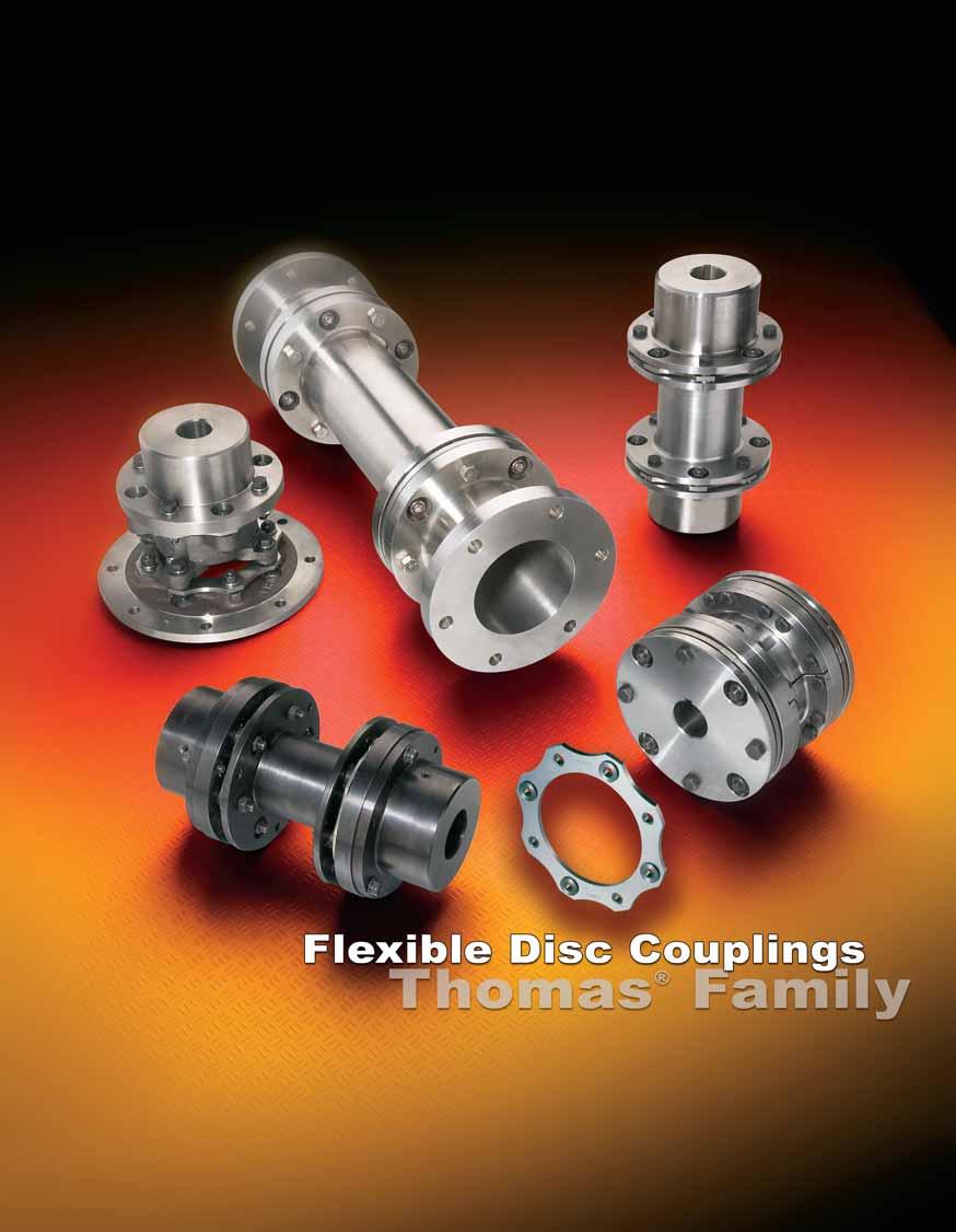
1 s
2 TALE OF CONTENTS s DESCRIPTION The Thomas Advantage Application Guide , 5 Misalignment Selection Procedures Service Factors Selection Examples ORDERING INSTRUCTIONS AND INFORMATION Ordering Instructions Tapered ore Information ore Specifications Taper Lock ushings Q.D. ushings Alignment Instructions Locknut Tightening Torques Application Data Form , 14 CLOSE COUPLED COUPLINGS Series 54RDG DZ-A, DZ SPACER COUPLINGS DZ-C Series Series , 19 CAST IRON COUPLINGS AMR CMR , 3 MR FLOATING SHAFT COUPLINGS Floating Shaft Types SN, SF, SV , 7 SN-GA SN Adjustable SINGLE FLEXING DISC COUPLINGS MR Single ST SN Single HIGH PERFORMANCE COUPLINGS Series , 33 THP MINIATURE COUPLINGS CC, CA C, CC CE PAGE SPECIAL FLEXILE DISC COUPLINGS , 38, 39

3 s THE REX THOMAS ADVANTAGE M.T. Thomas revolutionized the coupling industry by inventing the flexible disc coupling in Today Thomas engineers continue to improve the disc coupling through design innovation, modern materials and lean manufacturing processes. The Rex Thomas disc coupling is manufactured within a certified ISO 9001 quality system and is unsurpassed in its reputation for quality, reliability and easy maintenance features. The flexible disc packs are engineered for infinite life when applied within the published ratings and environmental guidelines. Our experience and dedication to conservative design standards assures maximum reliability on the most critical drive systems. DISC COUPLING ENEFITS No lubrication Visual inspection No backlash Low restoring forces Wide temperature range REX THOMAS ENEFITS High reliability road range of styles and sizes Extensive engineering support Custom design capability Global support DISC PACK Rex Thomas disc couplings are known for high reliability. The Tpack advanced technology flexible disc element makes maintenance easy and provides additional torque density. This high quality design functions with our current products and already installed Thomas disc couplings, performing in a variety of applications worldwide. Unitized pack for easy assembly and maintenance, alternating single headed bushings to provide full fastener bearing area and retrofitability into Series 5, AMR, CMR, and SN style coupling sizes Series 54RDG increased torque density and speed potential for close coupled applications. Patent Pending OTHER NEW ITEMS IN THIS CATALOGUE Series 71 eight bolt design uses our popular Series 71 design with drop out center section assembly and Tpack disc pack, we are able to provide significant increases in torque capacity allowing for a smaller coupling selection and high speed potential. * Tpack not available for size SN **Tpack used in Series 71 not interchangeable with Series 5, AMR, CMR or SN. Note: Dimensions subject to change. Certified dimensions of ordered material furnished on request. 3
4 REX THOMAS COUPLING APPLICATION GUIDE s Type Typical Applications Torque Range* (lb.-in.) RPM* Range Max.* ore (in.) Page Number Max. Ang. Misalignment Per Disc Pack Series 54RDG Close-coupled applications. Suitable as replacement for gear and grid couplings Up Up to to /3 1,74,800 10,500 DZ- Mixers, Compressors, Agitators, lowers and Fans, Centrifugal Pumps, Conveyors Up Up to to / 43,400 9,000 Series 5 Pumps & Compressors (Centrifugal, Rotary, Lobe, and Axial), Speed Increasers, Fans, Dynamometers Up Up to to /3 3,390,000 15,000 Series 71 Pumps & Compressors with popular Shaft Separation Standards. lowers, Fans, Speed Increasers Up Up to to , 19 1 / 1 /3 1,677, 0,800 DZ-C Process Pumps with ANSI, API, and other shaft separation standards. lowers, Fans, Mixers, Compressors, Conveyors Up Up to to / 50,000 9,500 AMR Reciprocating Pumps and Compressors, Fan Drives, lowers, Heavy-duty Industrial Drives, Crushers, Extruders, Hoists, Dredges, Generators, Chippers, Calender, Mill Drives, Conveyors Up Up to to /3,840,000,500 CMR Engine Drivers, Reciprocating Pumps and Reciprocating Compressors, Heavy-duty industrial drives where flywheel mounting is required Up Up to to 15.5, 3 1 /3,840,000,500 MR lowers, Fans, Crushers, Marine Drives, Dredge Pumps, Hoists, Heavy-duty Industrial Drives. Reciprocating Pumps and Compressors, Paper Mill Drives, Conveyors Up Up to to /3 61,000 1,800 SN-GA Pulp and Paper machines, Line Shafts, Pelletizers, Crushers and Mill Drives. Replacing long span gear couplings, bolting to existing rigid hubs Up Up to to N/A 5 1 /3 1,107,000 1,800 * These ratings are for cataloged coupling sizes. For special requirements, consult Rexnord Industries, Inc. 4 Note: Dimensions subject to change. Certified dimensions of ordered material furnished on request.
5 s REX THOMAS COUPLING APPLICATION GUIDE Type Typical Applications Torque Range* (lb.-in.) RPM* Range Max.* ore (in.) Page Number Max. Ang. Misalignment Per Disc Pack SN SF Turbines, Pumps, Compressors, Test Stands, Generators, Speed Increasers, Fans (Cooling Tower, Mine Ventilating, Forced and Induced Draft), Paper Mill Drives, Line Shafts, Printing Machines, Pumps. Available as a standard in corrosion-resistant materials Up Up to to , 7 1 /3 1,466,000 3, Vertical Drives such as Sewage Pumps, Printing Machines, Marine Pumps. Available as a standard in corrosionresistant materials Up Up to to , 7 1 /3 1,466,000 3, SV ST Accommodates angular misalignment only. Three-bearing applications where radial load is supported by the coupling, such as single-bearing generators, V-belt sheaves, etc. Up Up to to /3,000,500 MR Single SN Single THP Accommodates angular misalignment only. May be used with solid intermediate shafts for applications listed for MR. Not intended as a radial-load-supporting coupling Accommodates angular misalignment only. May be used with intermediate solid shaft for applications similar to MR, but with high speed capacity. Available in corrosion-resistant materials Turbines, Pumps, Compressors, Speed Increasers, Test Stands Up Up to to /3 1,040,000,500 Up Up to to /3 838,800 7,100 Up Up to to /4, 1 /3 579,000 8,500 Series 63 Turbines, Pumps, Compressors, Test Stands, Generators, Speed Increasers Up Up to to , 33 1 /4 1,150,000 36,000 Miniature s Tachometers, Encoders, Switches, all Screws, Test Stands, Pumps, Compressors, Centrifuges, Theodolites, Sonar, Radar, Scales, Carburetors Up Up to to / - 150,000 Adjustable Length SN Same applications as SN but where axial and/or angular adjustment is desired. Many sizes in stock for emergency break down replacement Up Up to to /3, 1,800 * These ratings are for cataloged coupling sizes. For special requirements, consult Rexnord Industries, Inc. Note: Dimensions subject to change. Certified dimensions of ordered material furnished on request. 5
6 REX THOMAS FLEXILE COUPLINGS s A flexible coupling is a device used to connect the ends of two shafts, transmit torque, and at the same time, accommodate slight misalignments which develop in service. The primary functions of all flexible couplings are: 1. To transmit power from one shaft to another, efficiently and effectively.. To accommodate slight shaft misalignments which develop in service. The secondary functions of flexible couplings are: 1. Protect connected equipment. a. Absorb shock, vibration and pulsations. b. Decrease cross load on bearings. c. Accept load reversals. d. Minimize backlash.. Minimize installation and maintenance difficulties. Shafts become misaligned during operation because of settling foundations, the effects of heat, vibration, etc. These misalignments take place in the form of angular misalignment, parallel misalignment, or axial movement of the shafts. Therefore, to get full service life from any flexible coupling, it is necessary to: 1. ASSURE PROPER SHAFT ALIGNMENT DURING INITIAL INSTALLATION.. OCCASIONALLY CHECK FOR AND CORRECT SHAFT MISALIGNMENTS DURING OPERATION. CAUTION All rotating power transmission products are potentially dangerous and must be properly guarded. Never operate coupling without an OSHA approved guard. What is Misalignment? VIEW FROM AOVE VIEW FROM AOVE VIEW FROM AOVE VIEW FROM FRONT VIEW FROM FRONT VIEW FROM FRONT USUAL MISALIGNMENT PARALLEL MISALIGNMENT ANGULAR MISALIGNMENT ANGULAR and PARALLEL AXIAL CAPACITY Misaligned shafts not properly coupled are subject to severe stresses which damage bearings and seals. Any or all of the misalignments shown in the above diagrams are present in all connected drives. Therefore, it is imperative that flexible couplings be used to avoid costly damage to your equipment. Initial alignment of machinery is one of the most critical factors affecting coupling performance and reliability. Each particular style of coupling has its own misalignment capabilities. The installation and alignment instructions outline the initial alignment requirements. These initial values are approximately one-third of the total coupling misalignment capacity. This means that the coupling has ample reserve to compensate for operational misalignments which develop as a result of bearing wear, foundation settling, thermal growth, pipe strain, etc. However, the closer the initial alignment, the more reserve margin a coupling has to compensate for misalignments during the life of the machine. A coupling that operates with large amounts of misalignment will have a limited life, while a coupling operating within capacity will have infinite life. The customer and coupling manufacturer must mutually select the correct size and type coupling for the application. Good service life will then become a reality if proper installation and alignment procedures are followed. The following pages show basic coupling arrangements and load classifications based on years of experience in coupling applications in all phases of power transmission. Any unusual operating or misalignment conditions should be referred to Rexnord to assure proper selection of size and type of coupling. 6
7 s REX THOMAS COUPLING SELECTION SELECTION PROCEDURES SERVICE FACTORS Service Factors are a means of classifying different equipment and applications into various load classifications. Due to variations in application of equipment, service factors are used to adjust equipment ratings to accommodate for variable loading conditions. Load Classifications Continuous service and running loads vary only slightly. Torque loading varies during operation of the equipment. Torque loading varies during operation, frequent stop/start cycles are encountered. For shock loading and substantial torque variations. For heavy shock loading or light reversing drives. Reversing torque loads do not necessarily mean reversal of rotation. Depending upon severity of torque reversal, such loads must be classified between medium and extreme. Service Factors Consult Rexnord Industries, Inc. Close Coupled s and Spacer s The need for flexible couplings in high speed applications continues to grow. Thomas couplings have been particularly successful in these applications due to their desirable qualities of being in balance and staying in balance. Thomas couplings are manufactured with an inherent high level of balance quality designed in to the product. That is, components are manufactured to close tolerances and concentricities, and fits between mating parts are carefully controlled. The balance requirements of a flexible coupling are in reality governed by the characteristics and requirements of the connected equipment; in other words, the dynamics of the system dictate the required coupling balance quality. Different systems operating at the same horsepower and speed may vary in their balance requirements, depending on the sensitivity of the system to coupling unbalance. Some of the factors affecting sensitivity are: Stiffness of bearing supports Distance between bearing supports Shaft overhang between bearing and coupling Shaft diameter relative to coupling weight The American Gear Manufacturers Association (AGMA) has developed Standard 9000-C90, entitled alancing Classification for DISC COUPLING SELECTION PROCEDURE The following procedure can be used to select Disc couplings for most applications. For applications involving other than normal loading or design, special consideration must be given to coupling selection. Rexnord application engineers are readily available for selection, advice and assistance. 1. Determine HP/100RPM: HP/100 RPM = Horsepower x 100 RPM. Determine Service Factor: Select the proper Service Factor from Table. Note, if not listed, see Load Classification Table. Note: The Service Factor Table considers the driven equipment only and assumes a normal electric motor or turbine driver. For prime movers of the reciprocating type (engines, etc.) add the following to the Service Factor: For 8 or more cylinders, add 0.5 For 6 cylinders, add 1.0 For 4 cylinders, add 1.5 For less than 4 cylinders, consult Rexnord Industries, Inc. 3. Select the : Turn to the page describing the selected coupling type and select the smallest coupling capable of transmitting the calculated HP/100 RPM at the proper Service Factor. 4. Check Limiting Conditions: a. Check maximum speed (dynamic balancing may be required see page 6) b. Check maximum bore. c. Check other dimensions such as shaft separation, overall length, O.D., etc. d. Check to be sure that the maximum torque to be transmitted, such as start-up or stall torques, do not exceed the coupling s Peak Overload Torque Rating. Note: Variable frequency and synchronous motors and certain induction motors produce transient torques several times the continuous rating of the unit. Consult motor manufacturer. 5. Refer to page for Ordering Information. Flexible s which attempt to relate the above factors, and to also define coupling balance quality as related to the system factors. Rexnord has developed recommendations for coupling balancing based on AGMA 9000-C90 and the inherent balance level of the various couplings shown in this catalog. These are shown on the data sheets as follows: Max RPM Not alanced. This is the maximum operating speed where the coupling will operate under normal conditions, and not create unacceptable vibration due to coupling unbalance. This is based on many years of operating experience on a wide variety of drive systems. Max. RPM alanced. This is the maximum operating speed where the coupling, after balancing, will still be compatible with the typical drive system. Consult Rexnord Industries, Inc. for speed requirements in excess of this value; special designs or manufacturing procedures may be required. Certain coupling types are not suitable for dynamic balancing, and should not be used if balancing is required. These types are: Type AMR Type CMR Type MR Type ST Series 63 and THP couplings are always furnished dynamically balanced in accordance with the requirements of the application. Note: A coupling is a critical component of any drive system. The basic coupling selection criteria is used to determine the size and style only. It is recommended that the system be analyzed for torsional and lateral stability using the specific coupling mass elastic data. The coupling weight, inertia, lateral stiffness, and torsional stiffness are available for this system analysis. It is the responsibility of the coupling user to assure the system, with the coupling as a component, properly functions. 7 S a g
8 s REX THOMAS COUPLING SELECTION TYPICAL SERVICE FACTORS MOTOR AND TURINE DRIVEN EQUIPMENT* AGITATORS Pure Liquids Variable Density ALTERNATOR LOWERS Centrifugal Lobe Vane RIQUETTER MACHINES CAN FILLING MACHINES CANE KNIVES CAR DUMPERS CAR PULLERS CLAY WORKING MACHINERY COMPRESSORS Centrifugal Lobe, Vane, Screw Reciprocating - Multi-Cylinder..Consult Rexnord Industries, Inc. Axial CONVEYORS - uniformly loaded or fed1.5 CONVEYORS - heavy duty - not uniformly fed CRANES AND HOISTS CRUSHERS DREDGES Cable Reels Conveyors Cutter Head Drives Jig Drives Maneuvering Winches Pumps Screen Drives Stackers Utility Winches ELEVATORS ucket Centrifugal Discharge Escalators Freight Gravity Discharge EXTRUDERS Plastic Metal FANS Centrifugal Forced Draft (Hostile Environment) 1.5 Induced Draft (Hostile Environment)1.5 Axial Forced Draft (Hostile Environment) 1.5 Induced Draft (Hostile Environment)1.5 Mine Ventilation Cooling Towers Light Duty lower & Fans FEEDERS Light Duty Heavy Duty FOOD INDUSTRY eet Slicer Cereal Cooker Dough Mixer Meat Grinders Can Filling Machine ottling Application Typical Service Factor Application Typical Service Factor GENERATORS Non-Welding Welding HAMMER MILLS LUMER INDUSTRY arkers - Drum Type Edger Feed Live Rolls Log Haul - Incline Log Haul - Well Type Off earing Rolls Planer Feed Chains Planer Floor Chains Planer Tilting Hoist Slab Conveyor Sorting Table Trimmer Feed MACHINE TOOLS ending Roll Plate Planer Punch Press - Gear Driven Tapping Machines Other Machine Tools Main Drives Auxiliary Drives METAL MILLS Draw ench - Carriage Draw ench - Main Drive Forming Machines Slitters Table Conveyors Non-Reversing Reversing Wire Drawing & Flattening Machine..0 Wire Winding Machine MILLS, ROTARY TYPE all Cement Kilns Dryers & Coolers Kilns Pebble Rod Tumbling arrels MIXERS Concrete Mixers Drum Type OIL INDUSTRY Chillers Oil Well Pumping Paraffin Filter Press Rotary Kilns PAPER MILLS arker Auxiliaries, Hydraulic arker, Mechanical arking Drum (Spur Gear Only) eater & Pulper leacher Calenders Converting Machines, except Cutters, Platers Couch Cutters, Platers Cylinders Dryers Felt Stretcher Felt Whipper Jordans Log Haul Typical Application Service Factor Presses Reel Stock Chests Suction Roll Washers and Thickeners Winders PRINTING PRESSES PULLERS arge Haul PUMPS Centrifugal General Duty (Liquid) oiler Feed Slurry (Sewage, etc.) Dredge Reciprocating Double Acting Single Acting 1 or Cylinders or more Cylinders Rotary - Gear, Lobe, Vane RUER INDUSTRY Mixer - anbury Rubber Calendar Rubber Mill ( or more) Sheeter Tire uilding Machines Tire & Tube Press Openers Tubers and Strainers SCREENS Air Washing Rotary - Stone or Gravel Traveling Water Intake Vibratory SEWAGE DISPOSAL EQUIPMENT..1.5 SEWAGE TREATMENT PUMPS TEXTILE INDUSTRY atchers Calenders Card Machines Cloth Finishing Machines (washers, pads, tenters) (dryers, calenders, etc.) Dry Cans Dryers Dyeing Machinery Looms Mangles Nappers Soapers Spinners Tenter Frames Winders (Other than atchers) WINDLASS WOODWORKING MACHINERY * Service Factors in this table are for driven equipment based on smooth prime movers such as electric motors and turbines. For reciprocating prime movers, such as diesel or gas engines, add the following to the Service Factor: For 8 or more cylinders, add 0.5 For 6 cylinders, add 1.0 For 4 cylinders, add 1.5 For less than 4 cylinders, consult Rexnord Industries, Inc.
9 s REX THOMAS FLEXILE DISC COUPLINGS SELECTION EXAMPLE A 50 HP electric motor is driving a dredge pump at 1,800 RPM. The shaft size of the motor is 3 /8 the shaft of the pump is 1 /8. The distance between the shaft ends (DSE) is 5 inches. The environment is 150 F. HP/100 RPM = 50 HP 100 = HP/100 RPM 1800 RPM OR Application Torque = 50HP 63,000 = 8,750 lb.-in 1,800 Service factor (See typical service factor on page 8) =.0 Use chart on page 17 for HP/RPM Application torque requirements Service factor 8,750 = 17,500 Excerpt of page 17 Series 5 OR ➅ Max. ore A ➁ Std. C ➁ Stocked C Min. C & & & Max Horsepower Per 100 RPM ➂ M ax. RPM Max. Peak Weight Overload Torque Service Factor ➄ Continuous Not Torque 1.0 alanced alanced (lb.-in.) (lb.-in.) ,000 15,000, 5, , 15,000 5, 10, ,50 15,000 10,500 1, ,100 14,000 17,500 35, ,900 13,000 3,830 65, , 11, 51,400 10,800 Torque requirements suggest a size ore size requirement indicates a size is required DSE requirement is met by with standard 5 inch C dimension Selection = Series 5, with standard 5" dimension 9
10 REX THOMAS FLEXILE DISC COUPLINGS ORDERING INSTRUCTIONS s PROCEDURES The following bore will be furnished when tolerance and type of fit are not specified. (Does not apply to miniature and DZ stocked bores.) Nominal ore Dia. Over Thru ore Tolerance 1 1 / / See page 11 for types of fits and shaft diameters. 1. Quantity. and Type 3. ore s 4. Keyway and Setscrew s (if non-standard) 5. Dynamic alancing if required 6. Additional Data (where applicable) (a) Disc Pack material (if other than Tomaloy). (b) Free or interference fit on shafts (if shaft diameters are given). (c) Complete details on tapered bore requirements, see below. (d) On DZ-A s (1) Identify bore of standard hub, and bore of extended hub. (e) On SN, SF, and SV s (1) Corrosion Resistance Class () L Dimension (3) Dynamic alancing if required (4) Sketch of Stub shaft (SF only) if non-standard (5) On SV, identify bore of upper hub and lower hub (6) Operating speed required (f) On MR s (1) Solid Shaft Diameter, if ordered () L Dimension (g) On CMR s (1) Adapter; 5 (a) Outside Diameter (b) olt Circle Diameter (c) olt Hole Diameter (d) Number of olts and Spacing REX THOMAS FLEXILE DISC COUPLINGS ORDERING INFORMATION TAPERED ORES INFORMATION REQUIRED 1. Drawing of HU showing complete bore and keyway details. OR. Drawing of SHAFT with dimensions shown below, allowing Rexnord to bore hubs to suit. SUPPLEMENTAL TAPER ORE INFORMATION With connected equipment in fixed position, the following additional information is necessary: Dimensions V and X must be given when one or both connected machines are fixed on their bases. Advise if dimension X is fixed, or if variable between what limits. W KEYWAY AVAILALE LENGTH OF SHAFT N E P S T (LD) Large Diameter, Specify in Decimals. (S) Length of Taper, Measure parallel to Shaft centerline. (T) Taper per Foot, Difference in Diameter in one foot length. (P) Clearance space for drawing Hub up on tapered shaft. Usually 1 /8" or 1 /4", depending on shaft size and taper. Keyway: Width, Depth. Note: Specify if keyway is parallel to Taper or if parallel to shaft center line. Specify depth at larger diameter of Taper if keyway is parallel to shaft center line. LD N E P A fixed X dimension may require altered or special coupling hubs. Often the straight bored hub can be positioned on its shaft allowing the use of a standard coupling. See illustrations below. Consult AGMA Standard 900-A86 Taper ores for Flexible s for new applications. HU COUNTERORED V C X SHAFT PROJECTS HU SHORTENED 10 Note: Dimensions subject to change. Certified dimensions of ordered material furnished on request.
11 s ORE SPECIFICATIONS s will be bored in accordance with AGMAStandard 900-A86. The type of bore fit normally supplied by Rexnord is listed below. Straight ore Class I Clearance Fit Stocked DZ Straight ore Interference Fit on ore-to-order s Taper ore To Customer Specification AMR, MR, CMR, SN, SF, Straight ore Interference Fit on All ores SV, ST, 5, Taper bore To Customer Specification 54RDG, 71 Series 63/THP All ores per Customer Specification Miniatures See page Unless specified otherwise by customer. Note: Rexnord recommends an interference fit be used whenever possible. ore REX THOMAS FLEXILE DISC COUPLINGS ORDERING INFORMATION Standard Keyways Dimensions Tolerances (inch) Nominal Keyway Keyway Tolerance Shaft Diameter Depth Width Sq. Rect. Close Side Free Side Over Thru Width ➁ ➁ Fit ➂ Fit ➃ Depth 5 / 16 7 / 16 7 / 16 9 / 16 9 / 16 7 /8 7 /8 1 1 /4 TAPER-LOCK AND QD USHING SELECTION CROSS REFERENCE In order to cross reference tapered bushing and bore sizes to a Hubs bored for Q.D. or Taper-Lock bushings will be modified for coupling selection, the following tables will cover the majority of cases. proper fit with bushing length. Consult Rexnord Industries, Inc. for * Reg. TM of others. specific dimensional data. Taper-Lock* Type If specific reference to the coupling series or type is not found in the and Type table, i.e. special designs, comparison of the shaft size with the ushing Maximum SV, SF, Series Series AMR, MR, maximum bore table only, will indicate the correct taper bushing in ore DZ SN 5 54RDG CMR, ST the left side of each table. Other flange style and compression / bushings can be used with coupling hubs /4 163 Q.D. Type /8 01 and Type /8 01 ushing Maximum SV, SF, Series Series Series AMR, MR, /8 01 ore DZ SN 5 54RDG 71 CMR, ST JA 1 1 / / 63 SH 1 5 / / 63 SDS 1 15 / SD 1 15 / SK / SF 15 / / 401 E 3 7 / N ote: C Dimension will be as listed for all couplings. F 3 15 / F Dimension will vary according to bushing selection. ➄ With shallow keyway. Key supplied with bushing where shallo w Consult Rexnord for F dimensions with bushings. keyway is furnished. Note: Dimensions subject to change. Certified dimensions of ordered material furnished on request / 3 1 /8 3 / 16 1 /4 3 / 64 1 / 16 / 64 / / /8 / 3 5 / 3 1 /8 3 / 16 1 / /4 3 / / 16 7 / 3 3 /8 1 / /4 1 3 /8 5 / /8 1 3 /4 3 / /4 1 /4 1 / /4 3 /4 / /4 3 1 /4 / /4 3 3 /4 /8 / 16 / /4 4 1 / 1 1 / 3 /8 4 1 / 5 1 / 1 1 /4 5 /8 7 / / 6 1 / 1 1 / 3 /4 1 / / 7 1 / 1 3 /4 7 /8 3 / / / ➁ Rectangular keyways recommended for shafts over 6 1 /" diameter. ➂ Close Side Fit Keyways Recommended for reversing torque drives or other drives which are vibratory in nature, or where zero backlash is required. Customers must specify if a close side fit keyway is required. ➃ AGMA 900 Fit Keyways Recommended for use on smooth, unidirectional drives where fitting of key at assembly cannot be tolerated. An AGMA 900 fit keyway will be furnished on all couplings unless specified by customer. ore s (inch) Shaft Dia. Clearance Fit Class 1 I nterference Fit Shaft Dia. Clearance Fit Class 1 Interference Fit 1 / / / / / / / / / / / / / / / / / / / / / / / / Consult Rexnord for unlisted sizes or bores over 6-inch diameter.
12 REX THOMAS FLEXILE DISC COUPLINGS GENERAL ALIGNMENT INSTRUCTIONS s Correct installation and alignment will assure long life and smooth, trouble free service. Refer to specific instruction sheet, which accompanies shipment, for style of coupling being installed. Two methods are commonly accepted: 1. Reverse Indicator Method (preferred). Face/Rim Method (angular/offset) For complete alignment information, contact Rexnord Industries, Inc. THE REVERSE INDICATOR METHOD 1. Rigidly mount a dial indicator on one hub or shaft, reading the shaft or other hub out side diameter as shown. Compensate for indicator set-up sag. Rotate both shafts together. Adjust the equipment by shimming and/or moving so that the indicator reading is within maximum allowable variations for the coupling style.. Reverse the set-up as shown and repeat #1 above. 3. When the results of #1 and # above are both within maximum allowable variations for the coupling style the shafts are in good alignment. Angular Alignment. Rigidly mount a dial indicator on one hub or shaft, reading the face of the other hub flange, as shown in Figure. Rotate both shafts together making sure the shaft axial spacing remains constant. Adjust the equipment by shimming and/or moving so that the indicator reading is within maximum allowable variations for the coupling style. Parallel Offset. Rigidly mount a dial indicator on one hub or shaft, reading the other hub flange outside diameter, as shown in Figure 3. Indicator set-up sag must be compensated for. Rotate both shafts together. Adjust the equipment by shimming and/or moving so that the indicator reading is within maximum allowable variations for the coupling style. DISTANCE ETWEEN INDICATORS Figure Figure 3 Properly tightened locknuts are essential in achieving maximum coupling torque. This table suggests the approximate locknut tightening torque values of disc couplings. Torque should be measured at the locknut while it is being turned. The tightening torques apply to locknuts as received from the factory. If plated hardware is used, tightening torque must be modified to suit. Stainless steel hardware requires special consideration. The tightening torques must be reduced to 60% of the values shown. olt and locknut threads must also be liberally coated with a Series 71 Locknut and Capscrew Tightening Torques Locknut Torque lb.-ft. (lb.-in.) Capscrew Torque lb.-ft. (lb.-in.) 150 ( 130) (113) 175 ( ) (108) ( ) (108) (108) * * * * * * 70 LOCKNUT TIGHTENING TORQUES molybdenum disulphide grease if using stainless steel hardware. olting instructions for Series 63 s are included with coupling installation procedures. Disc s Approximate Locknut Torque lb.-ft. Types Types DZ DZ-A DZ- DZ-C SN, SF, SV, AMR, MR, ST 5, 54RDG DZ DZ-A DZ- DZ-C SN, SF, SV, AMR, MR, ST 5, 54RDG * * * * * * 5 * * * * ,800 Note: 1. These torque values are approximate for steel bolts with oil lubricated threads.. olts should be held from rotating while the locknuts are torqued to the values shown. * These locknuts are cadmium plated. 1 Note: Dimensions subject to change. Certified dimensions of ordered material furnished on request.
13 s APPLICATION DATA FORM ENGINEERED PRODUCTS Rex Thomas couplings are adaptable to virtually any special drive system. Please fill out this page and the facing page and send to Rexnord Industries, Inc. Operation, Warren, PA Telephone: (814) NAME: INQUIRY NO. T: TITLE: COMPANY: ADDRESS: COUPLING OPERATION DATA DATE QUOTED: CPLG. SIZE/STYLE: PHONE: DESIGN: Std. Rm. Spec. DATE: APPLICATION DATA DRIVER: DRIVEN: NEW APPL.: Yes No REPLACING: SERVICE: Cont. Intermit. TEMP.: Norm. F Max. F SERVICE FACTOR: CORROSION PROTECTION: Yes No PLATE/COAT.: THERMAL GROWTH: SE (Cold): SE (Hot): AXIAL FLOAT REQ D.±: CUSTOMER REQUIREMENTS WT: Solo Plate WR: WT/ CG Simulator KT: Puller Holes CG: Sketch NCR: Dwg. FN: Quote ALANCE CPLG.: Yes No ORDER NO.: DWG. NO.: QTY.: PRICE: DELIVERY: TORQUE DATA NOR. MAX. START TRIP H.P.: kw: RPM: Torque (In-Lbs): SPECIFICATION APPLICALE API-671: Yes No EDITION API-610: Yes No EDITION OTHER: DESIGN LIMITS WEIGHT: Yes No lbs. WR: Yes No lbs.-in. KT: Yes No x 10 6 in.-lb./rad. O.D.: Yes No in. MISALIGNMENT: Yes No ANG.: Deg./Element PARA.: in. Offset Axial ±: in. ALANCE HUS: No OTHER: DR.: DN. FIELD AL. TAPS: Yes No OTHER: SPECIAL NOTES: 13
14 APPLICATION DATA FORM ENGINEERED PRODUCTS s DIMENSIONAL DATA ORE/KWY DATA Driver: Driven: ore Dia: Straight: Taper (L.D.): Keyway : W. x Dp. W. x Dp. Depth From Opp. Side of ore at LD Depth From Opp. Side of ore at LD Kwy. Parallel To: C L Taper C L Taper Hydraulic Fit: Yes No Inter. Yes No Inter. Spine (Provide Details): P.D. Lg. P.D. Lg. Fig. Adapter: No. Holes No. Hole * Provide Sketch CD CD Spacing Spacing Pilot Dia. Pilot Dia. Pilot Hgt. Pilot Hgt. Other: SHAFT DATA Driver: Driven: LD S T (In/Ft Taper) THD SD P E N W Locknut LD SD S E P T (In/Ft) W N THD RH LH SE V SKETCH AREA SE (etween Shaft Ends) V (Available Shaft Length) 14

15 s REX THOMAS FLEXILE DISC COUPLINGS CLOSE-COUPLED SERIES 54RDG Series 54RDG couplings are reduced diameter gear and grid replacement couplings. Applications include any situation where the overall shaft to shaft spacing is minimal. The center member of the 54RDG is split axially, which permits maintenance of the couplings without moving the hubs or the connected equipment. Center member is piloted into the adapter providing high speed potential at high torque density. Construction Hubs and Center members: Carbon Steel olts: Alloy Steel Disc Packs: Stainless Steel Coatings Available: lack Oxide, Zinc, Cadmium When Specified, Series 54RDG couplings meet all requirements of API 610, or API 671. If application requires API specification, please consult Rexnord Industries, Inc. Other materials such as Tomaloy, Monel and Inconel are available; please consult Rexnord Industries, Inc. Misalignment: 1 /3 per disc pack **NEW DESIGN** **INCREASED TORQUE RATINGS** General Dimensions (inch) M ax ore* M ax ore* Interna l External A C C1* * F F1* * H N G C ** * F** * * Non-bored hubs available upon request. ** Hubs may be reversed for alternate shaft spacing *** oth hubs reversed A MAX. ORE EXTERNAL H C C F F C1 N F1 Patent Pending MAX. ORE INTERNAL G Engineering Data Max Horsepower Per 100 RPM Maximum RPM Maximum Peak Service Continuous Overload ➁ ➄ Factor Torque Torque W eight WR Axial Capacity 1 Not alanced alanced (lb.-in.) (lb.-in.) (lb.) ( lb.-in. ) (in.) , 10,500, 5, ± , 9, 5, 10, ± ,800 8, 10,500 1, ± , 8,400 17,500 35, ± , 7,400 3,830 65, ± ,000 6, 51,400 10, ± ,800 6, 66, , ± ,500 4, ,300, 88 1,160 ± ,300 5, ,300 68, 117 1,780 ± , 5, , , ,690 ± ,000 4, 46,400 49, ,970 ± ,900 4, 330, , ,970 ± ,800 3, , , ,900 ±0.10 1, 071 1, 3, 674,800 1,349, 657 9,000 ± , 331 1,550 3, ,800 1,677, ,400 ± , 71 1, 3, 1,078,,157,400 1,040 63,900 ± , 00 1, 3,000 1,73,000,546,000 1,60 88,900 ± , 735 1,300,800 1,74,000 3,448,000 1, ,000 ±0.156 F or ordering instructions, see Page See page 7 for explanation of RPM limits and balancing recommendations. ➁ Weight and WR with standard length hubs, maximum bore and standard "C". ➂ Extended hub length is designed longer in order to include a counter-bore for the threaded extension on a tapered shaft. ➃ Large hub length. For sizes not shown, consult Rexnord. ➄ All Thomas disc couplings meet NEMA frame sleeve bearing motor specifications without modifications or the addition of end-float restricting devices. Note: Dimensions subject to change. Certified dimensions of ordered material furnished on request. 15
16 REX THOMAS FLEXILE DISC COUPLINGS s CLOSE-COUPLED TYPES DZ, DZ-A, DZ- The standard DZ coupling has two hubs inverted inside the disc pack and is used where overall shaft to shaft spacing is minimal. DZ style has both hubs with inverted orientation. DZ-A style has one hub extended to permit taper boring. DZ- style has both hubs extended to allow for greater spacing where required. Construction Other materials such as Stainless Steel, Monel Hubs and Center Assembly: Carbon Steel and Inconel are available; please consult olts: Alloy Steel Rexnord Industries, Inc. Disc Packs: Tomaloy Misalignment: 1 / per disc pack Coatings Available: lack Oxide, Zinc, Cadmium A G P1 STD. HU STD. HU Axial Capacity A G STD. HU EXTENDED HU P Axial Capacity A G P EXTENDED HU EXTENDED HU Axial Capacity 1 T E C1 F1 DZ 1 1 T E C F DZ-A (one standard and one extended hub)* DZ- (two extended hubs)* General Dimensions (inch) ➁ ➄ A ➁ ➄ Standard Hub Maximum ore Extended Hub Maxmum ore 1 C1 C C3 E F1 F F3 G P1 P T Engineering Data Max. Horsepower Per 100 RPM ➂ Max. RPM Max. Peak Continous Overload ➃ Weight ➃ WR Axial Service Factor Not Torque Torque (lb.) (lb.-in.) Capacity 1.0 alanced alanced (lb.-in.) (lb.-in.) DZ DZ-A DZ- DZ DZ-A DZ- (in.) ,000 9, ± ,000 8, ± ,000 7, ± ,000 7, , ± ,500 6,500 1,60 1, ± ,000 6,000 1,, ± , 5,500 3,00 4, ± ,100 5, 5,500 8, ± , 4,800 8, 1, ± ,300 4,500 1,900 19, ± ,900 4,100, 33, ± , 3,900 33, 49, ,705 1,710 1,710 ± , 3, 43,400 65, ,168 3,170 3,70 ±0.154 For ordering instructions, see Page All Thomas disc couplings meet NEMA frame sleeve bearing motor specifications without modification or the addition of end-float restricting devices. ➁ Popular sized standard hubs bore with keyway and setscrew are stocked. See page 11 for stocked bore sizes. ➂ See Page 7 for explanation of RPM limits and balancing recommendations. ➃ Weight and WR at maximum bore. ➄ Hubs furnished without a finished bore will be solid. * Extended hubs can be supplied with straight bores or taper bores. 16 Note: Dimensions subject to change. Certified dimensions of ordered material furnished on request. T C3 F3

17 s REX THOMAS FLEXILE DISC COUPLINGS SPACER TYPE SERIES 5 Series 5 couplings are all purpose high speed, high torque couplings used where minimum coupling weight is desirable. They are commonly used on motor and turbine driven pumps, compressors and fans. Design modifications may be made to further reduce the coupling weight, making it an economic alternative to high performance disc and diaphragm couplings. Construction Hubs and Center Assembly: Carbon Steel olts: Alloy Steel Disc Packs: Tomaloy Tpack (-750 ) Coatings Available: lack Oxide, Zinc, Cadmium When Specified, Series 5 couplings meet all requirements of API 610, or API 671. If application requires API specification, please consult Rexnord Industries, Inc. General Dimensions (inch) ➅ Max. ➁ Std. ➁ Stocked Min. ore A C C C F G N & & & & & Other materials such as Stainless Steel, Monel and Inconel are available; please consult Rexnord Industries, Inc. Misalignment: 1 /3 per disc pack **INCREASED TORQUE RATINGS** Series 5 Engineering Data Max Horsepower Weight Per 100 RPM ➂ Maximum RPM Maximum Peak Change WR ➄ Continuous Overload ➃ Per inch ➃ Change Per Axial Service Factor Not Torque Torque W eight of C WR Inch of C Capacity 1 alanced alanced (lb.-in.) (lb.-in.) (lb.) (lb.) ( lb.-in. ) ( lb.-in. ) (in.) ,000 15,000, 5, ± , 15,000 5, 10, ± ,50 15,000 10,500 1, ± ,100 14,000 17,500 35, ± ,900 13,000 3,830 65, ± , 11, 51,400 10, ± , 10,500 66, , ± ,000 9, ,300, ± ,800 8, 134,300 68, , ± , 8, , , , ± ,500 7,100 46,400 49, , ± ,300 6, , , , ± ,150 5, 433, , , 61. ±0.10 1,071 1,950 5, ,800 1,349, , ± ,331 1,850 4, 838,800 1,677, , ± ,71 1,750 4,300 1,078,,157, ,. 0 ± ,00 1, 3,900 1,73,000,546,000 1,109 71,. 0 ± ,735 1,500 3, 1,74,000 3,448,000 1, , ± ,094 3,50 1,950,000 3,900,000 1, , ± ,689 3,100,35,000 4,650,000, , ± ,498,800,835,000 5,670,000 3, ,500 1, ± ,379, 3,390,000 6,780,000 3, , 1,. 0 ±0.18 All Thomas disc couplings meet NEMA frame sleeve bearing motor specifications without modification or the addition of end-float restricting devices. ➁ Additional C dimensions available. Consult Rexnord. ➂ Series 5 couplings meet AGMA Class 9 balance requirements as manufactured with interference fit bore and close fit keyway. If clearance fit and/or setscrews are required, please consult Rexnord. Seep age 7for explanation of RPM limits and balancing recommendations. ➃ Weight and WR at maximum bore and standard C dimension listed. ➄ alance recommendations based on AGMA Specification 9000-C90 Average Sensitivity. ➅ Consult Rexnord for minimum rough bore sizes. Note: Dimensions subject to change. Certified dimensions of ordered material furnished on request. 17 A G N Series 5 TAPER ORES ALSO AVAILALE C F


18 REX THOMAS FLEXILE DISC COUPLINGS s SPACER TYPE SERIES 71 Series 71 couplings are designed for applications requiring a spacer-type coupling such as ANSI, API and other process pumps. Series 71 couplings are most commonly applied on motor, turbine, and gear driven pumps, compressors and blowers. Series 71 is a simple three piece design. Hubs are piloted fit to the factory assembled center member. The piloting provides repeatable assembly of components for better dynamic balance characteristics. The center assembly simply drops out for fast installation or removal without special tools. The disc design allows for low flexing forces and high overload capacity. Construction Hubs and Center Assembly: Carbon Steel olts: Alloy Steel Disc Packs: Stainless Steel for 4 & 6 bolt designs Stainless Steel Tpack for 8 bolt design Coatings Available: lack Oxide, Zinc, Cadmium When Specified, Series 71 couplings meet all requirements of API 610, or API 671. If application requires API specification, please consult Rexnord Industries, Inc. enefits Three piece design features unitized center member assembly and two piloted hubs Unique jacking bolt feature compresses coupling for easy installation and removal of center section assembly. Other materials such as Monel and Inconel are available; please consult Rexnord Industries, Inc. Misalignment: 1 / per disc pack for 4 and 6 bolt designs, 1 /3 per disc pack for 8 bolt design A G MAX. ORE STANDARD HU EXTENDED HU E MIN. LARGE HU MAX. ORE A G MAX. ORE STANDARD HU EXTENDED HU E MAX. LARGE HU MAX. ORE C 1 C 1 ➂ ➃ 8 olt Design 4 & 6 olt Design Series 71 alance Recommendations 1038 Common surface for coupling pilot, alignment and field rebore Unique jacking bolt feature for removing center member assembly Factory assembled center member assembly AGMA CLASS 10 AGMA CLASS 11 CONSULT REXNORD Piloted hubs and center member assembly COUPLING SIZE AGMA CLASS 9 STANDARD Oversize bore capacity Self-locking, flanged hex head capscrews Note: 175 These recommendations and balance classes are based on AGMA Specifications 9000-C90, high sensitivity. If conditions exist other than as defined in 9000-C90, for sensitivity, consult Rexnord Industries, Inc.. The above information should be 150 used as a guide only. AGMA Class 9 balance is furnished as standard when Series 71 couplings are finished bored with interference fits. OPERATING SPEED (x 1000 RPM) 18 Note: Dimensions subject to change. Certified dimensions of ordered material furnished on request.
19 s REX THOMAS FLEXILE DISC COUPLINGS SPACER TYPE SERIES 71 4 & 6 OLT General Dimensions (inch) ➆ ➆ & 1Hub Hub ➂ ➃ Std. Std. Min. Max. ore Max. ore A 1 C C E G Engineering Data Max Horsepower Per 100 RPM M ax. RPM Max. Peak Continuous Overload Service Factor ➅ Torque Torque 1 Not alanced alanced (lb.-in.) (lb.-in.) ,000 0, , ,300 17,000 1,630 3, , 16,000 3,060 6, ,800 14,000 7,60 14, , 13,500 13,400 6, ,650 1,000 19,300 38, , 11,000,500 45, ,000 10,000 40,400 80, , 9, 55, , , 8,300 84, , 145 4,150 7,800 91, 183,400 General Dimensions (inch) ➆ ➆ & 1Hub Hub ➂ ➃ Std. Std. Min. Max. ore Max. ore A 1 C C E G SPACER TYPE SERIES 71 8 OLT Stocked C Dimensions C Dimensions Weight Change WR ➁ Per inch ➄ Change Per Axial W eight of C WR Inch of C Capacity (lb.) (lb.) ( lb.-in. ) ( lb.-in. ) (in.) ± ± ± ± ± ± ± , ± , ± , ± , ±0.160 Stocked C Dimensions C Dimensions Engineering Data Max Horsepower Weight Per 100 RPM Maximum RPM Max. Peak Change WR Continuous Overload ➁ Per inch ➄ Change Per Axial Service Factor ➅ Torque Torque W eight of C WR Inch of C Capacity 1 Not alanced alanced (lb.-in.) (lb.-in.) (lb.) (lb.) ( lb.-in. ) ( lb.-in. ) (in.) ,500 14,000 17,500 35, ± ,800 1,500 3,830 65, ± , 11,500 51,400 10, ± , 10,500 66, , , ± , 9, ,300, , ± ,000 9, ,300 68, , ± , 8, 150, , , ± , 7,900 46,400 49, , ± ,900 7, , , , ± , 6, , , , ±0.10 1,071 3,300 6, 674,800 1,349, , ± ,331 3,100 5, ,800 1,677, 1, ,0 17 ±0.15 For ordering instructions, seep ages See page 7 for explanation of RPM limits and balancing recommendations. ➁ Weight and WR with standard length hubs, maximum bore and standard C. ➂ Extended hub length is designed longer in order to include a counter-bore for the threaded extension on a tapered shaft. ➃ Large hub length. For sizes not shown, consult Rexnord. ➄ All Thomas disc couplings meet NEMA frame sleeve bearing motor specifications without modifications or the addition of end-float restricting devices. ➅ Series 71 assembly meets AGMA Class 9 alance when finish bored with interference fits. ➆ Consult Rexnord for minimum rough bore sizes.. ➇ I f a block hub is supplied, extra capscrews will be provided for center member jacking featu re. Note: Dimensions subject to change. Certified dimensions of ordered material furnished on request. 19

20 REX THOMAS FLEXILE DISC COUPLINGS s SPACER TYPE DZ-C DZ-C couplings use the same disc pack and materials as the DZ. The center member is available in a variety of lengths and is recommended for ANSI and API process pumps. The drop out center member feature of this coupling allows for coupling maintenance and pump seal replacement with out disturbing the connected equipment. Construction Hubs and Center Assembly: Carbon Steel olts: Alloy Steel Disc Packs: Tomaloy Coatings Available: lack Oxide, Zinc, Cadmium Other materials such as Stainless Steel, Monel and Inconel are available; please consult Rexnord Industries, Inc. Misalignment: 1 / per disc pack 101 Stocked C Dimensions C Dimensions General Dimensions (inch) ➁➄ Cplg. Max ore A Std. C Min. C F G N Engineering Data Max Horsepower ➂ Per 100 RPM M ax. RPM Weight Max. Peak Change WR Service Continuous Overload ➁ Per inch ➄ Change Per Axial Factor Not Torque Torque Weight of C WR Inch of C Capacity 1 alanced alanced (lb.-in.) (lb.-in.) (lb.) (lbs.) ( lb.-in. ) ( lb.-in. ) (in.) ,000 9, ± ,000 8, ± ,000 8, ± ,000 7, , ± ,500 6,800 1,400, ± ,000 6,300 1,950 3, ± , 5, 3,530 7, ± ,100 5,500 6,300 1, ± , 5,000 9,900 19, ± ,300 4, 14,800 9, ± ,900 4,400 6,000 5, ± , 4,100 38,000 76, ,860 6 ± , 3,800 50, , ,40 36 ±0.154 For ordering instructions, see Page All Thomas disc couplings meet NEMA frame sleeve bearing motor specifications without modification or the addition of end-float restrictin g devices. ➁ Popular sized bores with keyway and setscrew are stocked. Consult your Rexnord representative for stock bore size availability. ➂ See page 7 for explanation of RPM limits and balancing recommendations. ➃ Weight and WR as shown are for maximum bores and standard. C. ➄ Consult Rexnord for minimum rough bore sizes. 0 Note: Dimensions subject to change. Certified dimensions of ordered material furnished on request. A G N N C F ALSO AVAILALE WITH TAPERED-ORE HUS AXIAL CAPACITY

21 s REX THOMAS FLEXILE DISC COUPLINGS TYPE AMR AMR couplings are used in heavy duty slow to medium speed applications, where high starting torque, shock loads, torque reversals or continuous alternating torque is present. The open lug type center member provides ample clearance for assembly while minimizing the space required for coupling installation. Construction Hubs: Cast Alloy Iron Center Section: s 750 are Cast Alloy Iron, s 800 and above are Cast Steel olts: Alloy Steel Disc Packs: Tomaloy Tpack (-750 ) Coatings Available: lack Oxide, Zinc, Cadmium General Dimensions (inch) Other materials such as Stainless Steel, Monel and Inconel are available; please consult Rexnord Industries, Inc. Misalignment: 1 /3 per disc pack **INCREASED TORQUE RATINGS** ➃ ➅ Cplg. Rough Max ore ore A C F G A G C F AXIAL CAPACITY Engineering Data Max Horsepower ➆ Per 100 RPM Max. Continuous Peak Overload ➁ ➄ Axial Service Factor ➂ Torque Torque W eight WR Capacity 1 Max. RPM (lb.-in.) (lb.-in.) (lb.) ( lb.-in. ) (in.) 9. 1,500 5,740 6, ± ,500 11,030 13, ± ,500 15,575 18, ± ,500 1,038 5,45 3 ± ,500 3,650 8, ± ,300 5,800 63, ± , 79,44 95, ,05 ± ,000 88, , 117 1,590 ± , ,15 163, 144,50 ± ,800,750 40, ,40 ± ,800 75, , ,0 ± , , , ,000 ± , , , ,800 ± ,03 1, , , ,900 ± ,91 1, 813, , , ± ,46 1, , 1,078,440 1,150 75, ± ,033 1,000 1,81,80 1,537,536 1,400 10,000 ± , ,487, 1,784,640 1,900 17,000 ± ,46 800,046,000,455,,80 45,000 ± , ,0,,64,640, ,000 ± ,787,387,000,864,400 3, ,000 ± ,957 3,14,000 3,748,800 5, ,000 ±0.4 For larger sizes, consult Rexnord. For ordering instructions, see Page All Thomas disc couplings meet NEMA frame sleeve bearing motor specifications without modification or the addition of end-float restricting devices. ➁ Weight and WR at maximum bore. ➂ Consult Rexnord if balancing is required. ➃ Consult Rexnord for minimum rough bore on sizes -. ➄ Special hub available for size with 6 /4 m ax. bore. Consult Rexno rd. ➅ Straight bores with no keyway require a steel hub. Consult Rexnord. ➆ The Peak Overload Torque is not an alternating torque limit. Note: Dimensions subject to change. Certified dimensions of ordered material furnished on request. 1


22 REX THOMAS FLEXILE DISC COUPLINGS s FLYWHEEL ADAPTER TYPE CMR CMR couplings are used in heavy duty slow to medium speed applications, where high starting torque, shock loads, torque reversals or continuous alternating torque is present. The open lug type center member provides ample clearance for assembly while minimizing the space required for coupling installation. The CMR couplings are designed with a flywheel adapter plate which bolts directly to the flywheel of an engine or compressor. The adapters are made to fit accurately into the recess in the flywheel, and external strains on the crankshaft resulting from the misalignment of the driven equipment is minimized. Construction Hubs: Cast Alloy Iron Center Section: s 750 are Cast Alloy Iron, s 800 and above are Cast Steel olts: Alloy Steel Disc Packs: Tomaloy Tpack (-750 ) Coatings Available: lack Oxide, Zinc, Cadmium **INCREASED TORQUE RATINGS** Other materials such as Stainless Steel, Monel and Inconel are available; please consult Rexnord Industries, Inc. Misalignment: 1 /3 per disc pack CMR coupling between engine and reciprocating compressor. FLYWHEEL ADAPTER INFORMATION Adapters can be furnished to accommodate virtually any flange design. Where possible, the user should select dimensions from the tables below, as these represent industry standards and thus are the most economical selection. Note that most sizes are available either with SAE bolting or Thomas heavy duty bolting. Available Adapters olting Light Duty Heavy Duty S ize Adapters Available in Shaded s (inch) Standard SAE olting Thomas olting A Adapter Diameter olt No. olt No. Tolerance (in.) Circle Holes (Dia.) Circle Holes (Dia.) S izes 95 to 1550 Adapting dimensions on request. Note: Dimensions subject to change. Certified dimensions of ordered material furnished on request. AVAILALE IN THESE SIZES
23 s REX THOMAS FLEXILE DISC COUPLINGS FLYWHEEL ADAPTER TYPE CMR General Dimensions (inch) ➃ ➅ Min. Rough Max A ore ore Dia. C D E F G FLYWHEEL OLT ➃ A E C F AXIAL CAPACITY G D Engineering Data Max Horsepower Per 100 RPM ➆ Max. Continuous Peak Overload ➁ ➄ Axial Service Factor ➂ Torque Torque W eight WR Capacity 1 Max. RPM (lb.-in.) (lb.-in.) ( lb. ) ( lb.-in. ) (in.) 9. 1,500 5,740 6, ± ,500 11,030 13, ± ,500 15,575 18, ± ,500 1,038 5, ± ,500 3,650 8, ± ,300 5,800 63, ± , 79,44 95, ,040 ± , 88, , 101 1,780 ± , ,15 163, 16,470 ± ,800,750 40, ,310 ± ,800 75, , , ± , , , ,50 0 ± , , , , ± ,03 1, , , ,300 ± ,91 1, 813, , , ± ,46 1, , 1,078, ,300 ± ,033 1,000 1,81,80 1,537,536 1, ,000 ± , ,487, 1,784,640 1, ,000 ± ,46 800,046,000,455, 1,950 47,000 ± , ,0,,64,640, ,000 ± ,787,387,000,864,400 3,30 567,000 ± ,957 3,14,000 3,748,800 4, ,000 ±0.4 For larger sizes, consult Rexnord. For ordering instructions, see pages All Thomas disc couplings meet NEMA frame sleeve bearing motor specifications without modification or the addition of end-float restricting devices. ➁ Straight bores with no keyway require a steel hub. Consult Rexnord. ➂ Maximum speeds are based on smallest available adapter O.D. For higher speeds, consult Rexnord. ➃ Flywheel bolts are not supplied with coupling. ➄ Weight and WR at maximum bore and minimum adapter diameter. ➅ Special hub available for size with 6 /4 max. bore. Consult Rexnord. ➆ C onsult Rexnord for minimum rough bore on sizes ➇ The Peak Overload Torque is not an alternating torque limit. Note: Dimensions subject to change. Certified dimensions of ordered material furnished on request. 3

24 REX THOMAS FLEXILE DISC COUPLINGS TYPE MR s Type MR couplings are recommended for heavy duty motor and engine driven service such as paper machines, grinding mills, dredges, and marine propulsion. The MR uses a solid intermediate shaft which can be furnished complete by Rexnord or fabricated by the user. Hubs are cast alloy iron, shafting is hot or cold-rolled steel, and disc packs are Tomaloy Tpack (-750 sizes) (stainless steel also available). Misalignment: 1 /3 per disc pack ➃ Cplg ➂ Rough ore General Dimensions (inch) Max ore A C F G A G C SPAN AXIAL CAPACITY F Max Horsepower Per 100 RPM ➃ Service Factor 1 Max. RPM , , , , , , , , , , , , 00 Engineering Data Max. Continuous Torque (lb.-in.) Peak Overload Torque (lb.-in.) 8 5,740 6, , , ,575 18, ,038 5, ,650 8, ,800 63, ,44 95, , , ,15 163, 3 5,750 40, , , , ,650 0 ➁ ➁ Weight WR (lb.) ( lb.-in. ) ,470 17,30 1,085 9,500 4, , Axial Capacity (in.) ±0.03 ±0.03 ±0.03 ±0.04 ±0.05 ±0.05 ±0.06 ±0.06 ±0.07 ±0.08 ±0.09 ± MR Shafting Selection Table ➃ Max Allowable Max Span (in.) at Max. Span (in.) Cplg. Shaft Dia. Max HP/100 For shaft Wt. Max. Allow Shaft For Various RPM (in.) Given Shaft Dia. (lb.) Wt , , For ordering instructions, see pages All Thomas disc couplings meet NEMA frame sleeve bearing motor specifications without modifications or the addition of end-float restricting devices. ➁ Weight and WR at maximum bore and minimum L. ➂ Consult Rexnord for minimum rough bore onsizes -. ➃ Consult Rexnord for larger sizes. 4 Note: Dimensions subject to change. Certified dimensions of ordered material furnished on request.

25 s REX THOMAS FLEXILE DISC COUPLINGS TYPE SN-GA Replaces troublesome gear couplings on pulp and paper applications. The Thomas one-piece, factory-torqued assembly is easy to install. This coupling is designed to bolt directly to existing rigid hubs using the gear coupling bolts. Axial shims are supplied for minor axial positioning adjustment. Construction Hubs and Center Assembly: Carbon Steel olts: Alloy Steel Disc Packs: Stainless Tpack Coatings Available: lack Oxide, Zinc, Cadmium Other materials such as Tomaloy, Stainless Steel, Monel and Inconel are available; please consult Rexnord Industries, Inc. Misalignment: 1 /3 per disc pack Gear (Falk) Thomas 6 500T 550T T T 750T 800T 850T Available Adapters # 1 1 / # # 1 / # 3 # 3 1 / # 4 # 4 1 / # 5 # 5 1 / # 6 #7 ( 1015) (100) ( 105) (1030) ( 1035) (1040) ( 1045) (1050) ( 1055) (1060) (1070) Other sizes available consult Rexnord. L (Typical) MD N (Typical) A Engineering Data Max Horsepower Per 100 RPM ➁ Max. Continuous Peak Overload Axial Service Factor Torque Torque Min. Capacity 1.0 (lb.-in.) ( lb.-in.) A L MD (3) N (in.) ,60 8, ,000 44, , 56, ,100 70, , , ,850 35, ➂ ,000 7, T 369 3, , T 47 69, 538, T ,000 8, T ,000 1,098, T 1, ,000 1,, T 1, ,000 1,816, T 1,756 1,107,000,14, For larger sizes, consult Rexnord. For ordering instructions, see Page All Thomas disc couplings meet NEMA frame sleeve bearing motor specifications without modification or the addition of end-float restricting devices. ➁ The Peak Overload Torque is not an alternating torque limit. ➂ Available with Tpackfor new couplings, not retrofittable in size. Note: Dimensions subject to change. Certified dimensions of ordered material furnished on request. 5


26 REX THOMAS FLEXILE DISC COUPLINGS FLOATING SHAFT TYPES SN, SF, SV s Floating shaft couplings are used to connect units which are relatively far apart. Such arrangements are particularly suited to transmit power into areas where moisture, dust or corrosive conditions would adversely affect the driving machinery. Floating shaft couplings operating speeds are dependent upon the length of span required. Refer to the speed/span table for speed recommendations. In addition, special balancing may be required for high speed service or for extended shaft lengths. Consult Rexnord Industries, Inc. for intended applications at speeds not covered in the table. The SN, SF and SV type couplings are furnished with stainless steel disc packs unless otherwise specified. TYPE SN Full-Floating Shaft Type SN couplings use a tubular center shaft, fabricated complete by Rexnord. Typical applications include cooling tower fan drives, paper machinery, printing presses, pumps and compressors. Connected shafts should be rigidly supported and long shaft overhang should be avoided. The tubular coupling shaft MUST NOT be supported with a bearing. They may be operated vertically if length does not exceed 36 inches. TYPE SF Semi-Floating Shaft Type SF couplings are a tubular shaft design with a stub shaft and bearing journal replacing the half-coupling on one end. They are typically used in tandem with the Type SN or Type SV where spans are too long for a single section of shafting. TYPE SV Vertical Floating Shaft s Type SV couplings are similar to the Type SN except that the lower half-coupling is modified to support the weight of the floating shaft. Typical applications include freshwater pumps, sewage pumps, and marine cargo pumps. They may be used in tandem with the Type SF where spans are too long for a single shaft. Corrosion Resistant Materials Types SN, SV and SF couplings are particularly suited to applications involving wet or corrosive conditions, for this reason they are all furnished with 300 series stainless steel disc packs. For extremely corrosive environments 316 stainless steel, Inconel 65 or Monel disc pack materials are available on request. As standard, these couplings are available in the following material classes. CLASS A All steel D Stainless steel except for zinc plated hubs All Steel zinc plated E All 300 series stainless steel Floating Shaft s C All Steel zinc plated w/stainless steel hardware Types SN, SV and SF center members are of Note: tubular construction, requiring special considerations for the operating speed and span 1. The stub shaft on the SF coupling is always furnished as unplated carbon steel in classes A,, C and D. length. The graph to the right may be used as a. s may be painted with acid and alkali resistant paints or coating besides the corrosion resistant classes listed. guide when determining whether it is desirable to balance the center member. Engineering Data The standard procedure for balancing of SN, SV Maximum Span (L) in Inches for Various Speeds - For SN & SV Maximum Span (X) in Inches for Various Speeds for SF and SF couplings includes straightening of the ➂ 3 3 ➁ tubular shaft prior to balancing. Many couplings RPM RPM RPM RPM RPM RPM RPM RPM RPM RPM RPM of this type operate relatively near to the lateral 50 See See resonant frequency of the coupling center 65 Footnote Footnote ➂ ➂ member, and special balancing techniques are often required Consult Rexnord Industries, Inc. for any application with speed in excess of RPM Types SF, SN and SV ,500 ➇ , T See See DYNAMIC ALANCING T Footnote Footnote REQUIRED T ➂ ➂ , T 800T See See , T Footnote Footnote See 95T ➂ ➂ See Footnote Footnote ➂ ➂ Do not use floating shaft couplings on equipment having long overhung shafts. 500 ALANCING ➁ Speeds 1800 rpm and under see page 1 for balancing recommendations. Consult NOT REQUIRED Rexnord on speeds in excess of 1800 rpm. Advise operating speed when ordering. ➂ F or spans not shown, consult Rexnord with application data for "span/speed" review. 10" 0" 30" 40" 50" 60" 70" 80" 10" Consult Rexnord for speeds in excess of 3 rpm. Advise speed when ordering. SPAN L IN INCHES 6 Note: Dimensions subject to change. Certified dimensions of ordered material furnished on request. SPEED IN RPM ALANCING MAY E REQUIRED DEPENDING ON APPLICATION
27 s REX THOMAS FLOATING SHAFT COUPLING TYPES SN, SF, SV A G AXIAL CAPACITY SN N A G AXIAL CAPACITY ➅ N L SPAN N F X SPAN SF SV L U T AXIAL CAPACITY ➅ G A NL E D L N General Dimensions (inch) ➄ oupling Max. ➂ ➂ ➁ Min. L SN SV SF ore A D E T U F G N NL SN SF ➇ ➇ T T T T T T T T Engineering Data Weight WR ➅ Max. Peak Weight Change ➃ WR Change Type SN ➄ Continuous Overload ( lb.) ➃ Per Inch ( lb.-in. ) Per Inch Axial Torque Torque of L of L Capacity (lb.-in.) (lb.-in.) SN, SV SF (lb.) SN, SV SF ( lb.-in. ) (in.) ± ± ± , ± ,30 4, ± ,50 8, ± , 17, ± ,60 8, ±0.036,000 44, ± , 56, ± ,100 70, ± , , , ± ,850 35, , ±0.067 ➇ 136,000 7, , ± T 3, , , ± T 69, 538, , ±0.09 T 411,000 8, , ±0.10 T 549,000 1,098, , ± T 631,000 1,, ,70 10 ± T 908,000 1,816,000 1, , ± T 1,107,000,14,000 1,40 91, ± T 1,466,000,93,000 1, , ±0.156 For larger sizes and longer spans, consult Rexnord. For ordering instructions, see pages All Thomas disc couplings meet NEMA frame sleeve bearing motor specifications without modification or the addition of end-float restricting devices. ➁ Shorter L requires special construction. Consult Rexnord. ➂ Shaft tolerances : 5 / 16 to 1 1 / /8 to 3 1 / Key furnished with standard keyway in SF stub shaft. ➃ Weight and WR at max. bore and min. L dimension. ➄ T suffix to coupling size indicates thin flange design. Consult Rexnord for larger sizes. ➅ Types SF and SV end-float is one half ± value shown for type SN. ➆ Consult Rexnord for minimum rough bore sizes. ➇ Not available with Tpack Note: Dimensions subject to change. Certified dimensions of ordered material furnished on request. 7

28 REX THOMAS SINGLE-FLEXING DISC COUPLINGS s TYPE ST ST couplings are designed for applications which require the coupling to support a substantial radial load while accommodating angular misalignment. Typical installations include units where one shaft is fully supported in its own bearings, and the other shaft is single-bearing supported. The radial load is transmitted through the coupling to the inner bearing of the other shaft. elt drives can be designed to utilize this type of coupling to eliminate a jack shaft bearing and transfer radial loading directly to a machine bearing. Such arrangements are economical and space saving. See the sketches below. Construction Hubs: Cast Alloy Iron olts: Alloy Steel Disc Packs: Tomaloy Tpack (-750 s) Coatings Available: lack Oxide, Zinc, Cadmium Other materials such as Stainless Steel, Monel and Inconel are available; please consult Rexnord Industries, Inc. Note: Single-flexing couplings cannot accommodate parallel misalignment. They are not suitable for connecting equipment where both shafts are held rigidly in their own bearings. SINGLE EARING MULTIPLE V-ELT DRIVE X MOTOR Y EARINGS COMPRESSOR GENERATOR General Dimensions (inch) 1 EARING ➆ Rough ore Max ore A F G N A G N F AXIAL CAPACITY Engineering Data Max Horsepower Per 100 RPM ➅ ➅ Max. Max. Peak Radial Smooth Pulsating Continuous Overload ➁ ➁ Axial L oad ➂ ➃ ➄ ➂ ➃ ➄ Torque Torque W eight WR Capacity (lb.) Col. 1 Col. Col. 3 Col. 4 Col. 5 Col. 6 Max. RPM (lb.-in.) (lb.-in.) ( lb. ) ( lb.-in. ) (in.) , , ± ,500 1,, ± ,500,400 3, ± ,500 4,80 6, ± ,500 6,740 10, ± ,300 9,640 14, ±0.08 1, , 14,900, ± , ,900 19,300 9, ,300 ± , ,500 4, 36, , ± , ,500 38,000 57, ,100 ± , ,500 54,800 8, 30 5, ± , , 77, , ,400 ± , ,100 10, , ,000 ± , , ,000 37, ,000 ± , , ,000 39,000 ±0.068 F or ordering instructions, see pages All Thomas disc couplings meet NEMA frame sleeve bearing motor specifications without modification or the addition of end-float restricting devices. ➁ Weight and WR at maximum bore. ➂ Col. 1 gives maximum HP/100 RPM permitted when combined with maximum radial load. ➃ Col. gives maximum HP/100 RPM permitted when combined with /3 maximum radial load. ➄ Col. 3 gives maximum HP/100 RPM permitted when combined with /3 maximum radial load. ➅ Maximum torque and peak overload torque are based on /3 maximum radial load. ➆ C onsult Rexnord for minimum rough bore on sizes -. 8 Note: Dimensions subject to change. Certified dimensions of ordered material furnished on request.

29 s REX THOMAS SINGLE-FLEXING DISC COUPLINGS TYPE MR SINGLE MR single couplings are used for single flex applications for light to moderate load. MR is also available in a double flexing design. Construction Other materials such as Stainless Steel, Monel Hubs: Cast Alloy Iron and Inconel are available; please consult Center Section: s 750 are Cast Alloy Iron, s 800 and above are Cast Steel Rexnord Industries, Inc. olts: Alloy Steel Misalignment: 1 /3 per disc pack Disc Packs: Stainless Tpack (-750 s) Coatings Available: lack Oxide, Zinc, Cadmium Note: Single-flexing couplings cannot accommodate parallel misalignment. They are not suitable for connecting equipment where both shafts are held rigidly in their own bearings. General Dimensions (inch) Rough ore Max ore A F G N A G TYPE MR SINGLE N AXIAL CAPACITY F Engineering Data Max Horsepower Per 100 RPM ➁ Max. Continuous Peak Overload ➂ ➂ Axial Service Factor Torque Torque Weight WR Capacity 1 Max. RPM (lb.-in.) (lb.-in.) (lb.) ( lb.-in. ) (in.) 9. 1,500 5,740 6, ± ,500 11,030 13, ± ,500 15,575 18, ± ,500 1,038 5, ± ,500 3,650 8, ± ,300 5,800 63, ± , 79,44 95, ± ,000 88, , 87 1,160 ± , ,15 163, 107 1,540 ± ,800,750 40, ,750 ± ,800 75, , ,930 ± , , , ,850 ± ,50 456, , ,300 ± , 03 1, , , , ± , 91 1, , , ,50 ± , 46 1, , 1,078, ,080 ± , 033 1,000 1,81,80 1,537,536 1,010 70, ±0.078 C onsult Rexnord for minimum rough bore on sizes -. ➁ All Thomas disc couplings meet NEMA frame sleeve bearing motor specifications without modification or the addition of end-float restricting devices. ➂ Weight and WR shown at maximum bore. Note: Dimensions subject to change. Certified dimensions of ordered material furnished on request. 9

30 REX THOMAS SINGLE-FLEXING DISC COUPLINGS s TYPE SN SINGLE Type SN single couplings are used for floating shaft applications where the user wishes to supply his own intermediate solid shaft, or for single-flexing applications where light-to-moderate radial loads occur. They are generally more economical than ST couplings. Construction Other materials such as Stainless Steel, Monel Hubs: Carbon Steel and Inconel are available; please consult olts: Alloy Steel Rexnord Industries, Inc. Disc Packs: Tomaloy Tpack Misalignment: 1 /3 per disc pack Coatings Available: lack Oxide, Zinc, Cadmium Note: Single-flexing couplings cannot accommodate parallel misalignment. They are not suitable for connecting equipment where both shafts are held rigidly in their own bearings. General Dimensions (inch) Max ore A F G N T T T T T A G TYPE SN SINGLE AXIAL CAPACITY N F Engineering Data Max Horsepower Per 100 RPM ➁ Max. Continuous Peak Overload ➂ Axial Service Factor ➂ Torque Torque W eight ➂WR Capacity 1 Max. RPM (lb.-in.) (lb.-in.) (lb.) ( lb.-in. ) (in.) , , ± ,500,30 4, ± ,000 4, 8, ± ,500 8, 17, ± , 14,60 8, ± ,800 3,830 65, ± ,500 51,400 10, ± ,100 66, , ± , ,300, ± , 134,300 68, 89 1,160 ± , 150, , ,580 ± T 391,800 46,400 49, ± T 54, , , ,130 ±0.046 T 688, , , 57 7,010 ±0.051 T 1,071, ,800 1,349, 390 1,100 ± T 1,331 1, ,800 1,677, 534 4,650 ±0.06 For larger sizes, consult Rexnord. For ordering instructions, see pages C onsult Rexnord for minimum rough bore on sizes -. ➁ All Thomas disc couplings meet NEMA frame sleeve bearing motor specifications without modification or the addition of end-float restricting devices. ➂ Weight and WR at maximum bore. 30 Note: Dimensions subject to change. Certified dimensions of ordered material furnished on request.

31 s REX THOMAS FLEXILE DISC COUPLINGS HIGH PERFORMANCE THP THP couplings are designed for use on high speed equipment where coupling size and weight must be kept to a minimum. Typically, these couplings connect prime movers such as motors, steam and gas turbines, rotary engines and gas expanders, to centrifugal and rotary compressors, generators, process and boiler feed pumps. Test stand and marine propulsion drives also benefit from this unique coupling design. The flexing elements are precision-stamped from a high strength 300 series stainless steel. This material has been used successfully for many years in Thomas couplings manufactured for helicopter drive shaft applications. Special materials for hubs, spacers and/or flexing elements are available to meet unique application requirements. Construction Hubs and Center Member: Heat Treated 4140 and 4340 Alloy Steel olts: Aircraft quality Alloy Steel with twelve point wrenching pattern Disc Packs: High Strength 300 Series Stainless Steel Coatings Available: lack Oxide, Zinc, Cadmium, other coatings available per customer specifications System Analysis A coupling is a critical component of any drive system. The basic coupling selection criteria is used to determine the size and style only. It is recommended that the system be analyzed for torsional and lateral stability using the specific coupling mass elastic data. The coupling weight, inertia, lateral stiffness, and torsional stiffness are available for this system analysis. It is the responsibility of the coupling user to assure the system, with the coupling as a component, properly functions. General Dimensions (inch) Other materials such as, Monel and Inconel are available; please consult Rexnord Industries, Inc. A C D E F Max ore ➁ Hydraulic G H L M N A G H L D E C F M CG N Engineering Data ➂➃ Max. ➄ ➄ 6 Max. Cont. Half Torsional Spacer Tube Per Inch Axial Standard Torque Max. ➄ ➄ Stiffness Capacity Cont. ore Rating Speed W t. WR C.G. Kt x 106 Kt x 106 Weight WR (Continuous) (in.) ( l b.-in. ) RPM (lb.) ( lb-in. ) (in.) (lb.-in./rad.) (lb.-in./rad.) (lb.) ( lb-in. ) (in.) ,000 8, ± ,000 4, ± ,000 3, ± ,000 19, ± ,000 19, ± ,500 17, ± ,50 17, ± ,000 15, , ± ,000 15, , ± ,000 13, , ± ,500 13, , ± ,000 1, , ± ,000 1, , ±0.05 For larger bores, consult Rexnord. ➁ May be reduced for smaller shaft sizes. Consult Rexnord. ➂ Minimum application factor to be applied = 1.5. ➃ Max. peak overload torque = 1.33 x max. cont. torque ➄ Information based on standard dimensional data shown. 6 Max. transient axial misalignment = 10% of values shown above. Consult Rexnord with specific application requirements. Note: Catalog dimensions subject to change. Note: Dimensions subject to change. Certified dimensions of ordered material furnished on request. 31

32 REX THOMAS FLEXILE DISC COUPLINGS s HIGH PERFORMANCE SERIES 63 Series 63 couplings incorporate a patented* one-piece disc/diaphragm flexing element for positive torque transmission with low restoring forces. This unitized assembly accommodates misalignment and transmits torque through a multiple disc arrangement which provides redundancy in construction with a high degree of reliability. Pilot plates on the sides of each flexing element give accurate, repeatable registration of coupling components, and retain original dynamic balance repeatability while protecting the flexing members from damage. Series 63 couplings are ideal for the most demanding drive requirements. Prime movers include motor, steam and gas turbines, rotary engines, and gas expanders. Driven equipment applications include centrifugal and rotary compressors, generators, test stands, boiler feed pumps and other multi-stage pumps, and marine propulsion drives. Special designs available for torsional tuning and reduced moment. * U.S. Patent Construction Hubs and Center Member: Heat Treated 4140 Steel olts: Alloy Steel Disc Packs: High Strength 300 Series Stainless Steel Coatings Available: lack Oxide, Zinc, Cadmium, other coatings available per customer specifications Other materials such as Stainless Steel, Monel and Inconel are available; please consult Rexnord Industries, Inc. A G H E D K N C 1 F 6 3 SERIES 63 COUPLINGS MAY E FURNISHED TO MEET REQUIREMENTS OF API 671 Max. ore Hydraulic H Keyed K A 1 General Dimensions (inch) 1 Std. C Min. C D E F G Max. Note: Dimensions subject to change. Certified dimensions of ordered material furnished on request. N Axial Capacity (in.) ± ± ± ± ± ± ± ± ± ± ± ± ± ±0.190 For Complete Selection, Dimensions And Mass-Elastic Data, Refer To Rexnord High Performance Catalog Or Contact Rexnord. Larger sizes are available. Consult Rexnord with specific application requirements. Standard dimension - may be modified as necessary. ➁ G dimension at listed maximum bore. Dimension G will vary depending on bore size.
 ( lb.-in. ) (lb.-in./rad.) (in.) (lb.) ( lb.-in. ) (lb.-in./rad.) Speed (RPM) Torque (lb.-in.) Torque (lb.-in.) 36,000 5,890 14, 7.76 16. 5 0.50 0.37 0.19 0.6 10. 5 8, 13, 34,000 16. 4 59. 8 1.78 0.")

33 s REX THOMAS FLEXILE DISC COUPLINGS HIGH PERFORMANCE SERIES 63 Engineering Data Standard Mass-Elastic Data ➂ Max. Peak Max. Continuous Overload Change Per Inch of C Cplg. Weight WR Kt x 106 C.G. Weight WR Kt x 106 (lb.) ( lb.-in. ) (lb.-in./rad.) (in.) (lb.) ( lb.-in. ) (lb.-in./rad.) Speed (RPM) Torque (lb.-in.) Torque (lb.-in.) 36,000 5,890 14, , 13, 34, , 1,100 5, ,500 37,800 94, ,100 64, , , 81,900 05, , 16, , , , ,000 43, , ,300 13, , , , 316, , , , , ,000 1,135, , ,850 9, ,000 1,575, , ,610 8, 903,000,58, , , ,500 1,150,000,875, , , Weight and C.G. data based on standard C dimension, maximum hydraulic bores (H) and hydraulic hub lengths (). Torsional stiffness (Kt) assumes a one-third shaft penetration factor. To determine Kt for a coupling with longer than standard "C" dimension, use the following formula Kt = where L = additional C dimension required Kt = torsional stiffnes s L Kt Kt change per inch of C dimension and 1/Kt - inverse of catalog value. For Complete Selection, Dimensions And Mass-Elastic Data, Refer To Rexnord High Performance Catalog Or Contact Rexnord. Larger sizes are available. Consult Rexnord with specific application requirements. ➂ Consult Rexnord with higher speed requirements. SERIES 63 UNITIZED FLEXING ELEMENT Features and enefits One-piece assembly no loose parts Replaceable in the field Individually balanced Assures repeatable coupling dynamic balance Piloted fit between hubs and spacer Complies with API 671 Visual inspection without coupling disassembly Compact and lightweight Easy to use UNITIZED FLEXING ELEMENT NOTE: A coupling is a critical component of any drive system. The basic coupling selection criteria is used to determine the size and style only. It is recommended that the system be analyzed for torsional and lateral stability using the specific coupling mass elastic data. The coupling weight, inertia, lateral stiffness, and torsional stiffness are available for this system analysis. It is the responsibility of the coupling user to assure the system, with the coupling as a component, properly functions. 33

 1 Torque A C F T Capacity (lb.-in.) 1 1 / 1 /4 1 / 3 1 7/ 3 0.")
34 REX THOMAS MINIATURE COUPLINGS THOMAS MINIATURE FLEXILE DISC COUPLINGS s GUIDE TO PROPER DESIGNATION OF HUS HU INSIDE OF CENTER MEMER CENTER MEMER STYLE CC HU OUTSIDE OF CENTER MEMER This coupling has both hubs inverted and is designed to fit shafts normally encountered at a given torque range. Ideal for use where space limitations require close coupling of the shafts. MATERIAL SPECIFICATIONS FOR STANDARD COUPLINGS: Hubs and Center Member: Aluminum Alloy, Anodized Rivets: rass Washers: rass Discs: Stainless Steel. eryllium Set screws: 18-8 Stainless Steel, Passivated Available with electronically insulated phenolic material General Dimensions (inch) 1 Torque A C F T Capacity (lb.-in.) 1 1 / 1 /4 1 / 3 1 7/ /4 3 /8 1 / / / 1 / / / 16 1 / 16 1 /8 1 1 / /4 1 5/ 16 1 / /4 1 1 / 16 1 /8 1 / / 1 3 / 16 1 /8 1 / /8 1 / Torque capacities are based on smooth drives with moderate torque fluctuations. Reduc e ratings to /3 the value shown for severe applications such as indexing drives where torque reversals occur. All Thomas disc couplings meet NEMA frame sleeve bearing motor specifications without modification or the addition of end-float restricting devices. A T C F AXIAL CAPACITY ➁ STYLE CA This design of our miniature coupling has one inverted hub to accept a normal shaft and one extended hub to accommodate oversize shafts. It also accommodates a larger shaft gap than the Style CC. A T C F AXIAL CAPACITY ➁ G General Dimensions (inch) 1 Torque A C F G T Capacity (lb.-in.) 1 1 / 1 /4 1 5/ / 64 5 / /4 3 /8 3 /8 1 1 /8 1 5/ / 1 5/ 3 1 / 3 5 / / 16 1 / 16 1 / 16 1 / 16 7 / /4 1 5/ 16 9/ 3 / / /4 1 1 / /8 1 3 / / 1 3 / /8 3 1 / 1 5 / /8 1 3 /8 4 1 /8 1 7 / Torque capacities are based on smooth drives with moderate torque fluctuations. Reduc e ratings to /3 the value shown for severe applications such as indexing drives where torque reversals occur. All Thomas disc couplings meet NEMA frame sleeve bearing motor specifications without modification or the addition of end-float restricting devices. 34

 1 Torque A C F G Capacity (lb.-in.) 1 1 / 1 /4 7 / 16 1 5/ 16 5 / 16 1.")
35 s REX THOMAS MINIATURE COUPLINGS STYLE C & CC This coupling design has both hubs extended to accept two oversized shafts. Shaft gap is larger than that of the Style CA or CC couplings. Style CC is the newest addition to our miniature coupling line. It offers clamping hubs that are an integral part of the coupling. The clamping hubs assure positive fit on the shafts. There are no loose parts to handle during installation. The Style CC coupling has the same dimensions and torque capacities as the Style C. Consult Rexnord Industries, Inc. for additional design and engineering data. AXIAL CAPACITY ➁ A G C F General Dimensions (inch) 1 Torque A C F G Capacity (lb.-in.) 1 1 / 1 /4 7 / / 16 5 / /4 3 /8 1 / / / / 7 /8 1 7 /8 5 / / 16 1 / /4 5 /8 7 / /4 1 5/ 16 1 / / / /4 1 1 / / / / 1 3 / 16 1 / / /8 1 / /8 1 Weight and WR at maximum bore. All Thomas disc couplings meet NEMA frame sleeve bearing motor specifications without modification or the addition of end-float restricting devices. STYLES CC, CA, C & CC RATINGS AND MASS ELASTIC DATA 1 1 Approx. Torsional Rigidity Max. Angular Misalignment, Max. Parallel Misalignment, ➁ Axial No. Max. RPM Approx. WR Kt x 106 Continuous Per Continuous Capacity Weight (oz.) ( oz.-in. ) (oz.-in./rad.) Flexing Element (in) (in.) 1 150, ± , ± , ± , ± , ± , ± , ± , ± Weight and WR at maximum bore. All Thomas disc couplings meet NEMA frame sleeve bearing motor specifications without modification or the addition of end-float restricting devices. Note: Dimensions subject to change. Certified dimensions of ordered material furnished on request. 35

36 REX THOMAS MINIATURE COUPLINGS s STYLE CE Two single-flexing units are connected by a tubular shaft in this type of miniature coupling. It s designed to span large distances between shafts. Ideal for those applications where a large amount of parallel misalignment is anticipated. AXIAL CAPACITY ➂ A G L F General Dimensions (inch) Weight Change ➁ Torque Capacity 1 W eight per inch of L A F G L (lb.-in.) (oz) (oz.) 1 1 / 1 /4 5 / /4 3 /8 1 5/ / Varies /8 Variable / 16 / 16 W ith /8 To Suit /4 5/ 16 L 1 1 / 16 Requirements Specified /4 1 1 / / / 1 3 / / /8 1 7 /8 1 Weight calculated at maximum bore and L = 1 inches. ➁ Torque capacities are based on smooth drives with moderate torque fluctuations. Reduce ratings to /3 the value shown for severe applications such as indexing drives where torque reversals occur. ➂ A ll Thomas disc couplings meet NEMA frame sleeve bearing motor specifications without modification or the addition of end-float restricting devices. ➃ For WR, misalignment capacities, and torsional rigidity, consult Rexnord. MINIATURE COUPLINGS STANDARD ORE SIZES CC, CA, C, CC & CE s ores ➁ ➂ (in.) ores ➁ ➂ (in.) Hub Inside Center Member Hub Outside Center Member Hub Inside Center Member Hub Outside Center Member , , , , , , , , , , , , , , , , , , , , , , , , , , , , , , , , , not available with rough bore. Other bore sizes can be furnished. Consult Rexnord. ➁ Tolerances. s 1 and 18, ±0.0003". Other sizes, ±0.0005". ➂ The largest bore shown for each hub is maximum allowable bore. If larger bore is required, consult Rexnord. 36 Note: Dimensions subject to change. Certified dimensions of ordered material furnished on request.
37 s SPECIAL FLEXILE DISC COUPLINGS REX THOMAS COUPLINGS The following pages illustrate a sampling of the special disc coupling products designed and manufactured by Rexnord Industries, Inc. For applications requiring special coupling designs, please contact your Rexnord Industries, Inc. representative. SN-EL - Extra Long Span Semi-Reduced Movement olt On Hub TORQUE-METER Torsionally Tuned Center Members Torque Meter Electrically Insulated s High Speed-Composite Tube reaker Pin -earing Style reaker Pin -ushing Style 37
38 REX THOMAS COUPLINGS s SPECIAL FLEXILE DISC COUPLINGS rake Drum Hub Motor-Tachometer Double Disc Packs Provide High Axial Capacity Hydraulic Hub Mounting Axial Limiting Stops Shrink Disc Hub Mounting Slide For Axial Positioning Clamp Hub Mounting 38
39 s TYPE SN ADJUSTALE REX THOMAS COUPLINGS Type SN adjustable couplings were developed as emergency replacements for standard Type SN couplings and are available from stock in most sizes required for cooling tower applications. Each shaft may be adjusted thru a four-inch length range, using a special compression bushing to lock the shaft in place once the length is set. A G N L N General Dimensions (inch) & Engineering Data Weight WR Change Change ➁ Per Inch of ➁ per inch of Axial Min. Adjustment W eight L WR L Capacity Max ore A G H L Range (lb.) ( lb. ) ( lb.-in. ) ( lb.-in. ) (in.) ± ± ± ± All Thomas disc couplings meet NEMA frame sleeve bearing motor specifications without modification or the addition of end-float restricting devices. ➁ Weight and WR at maximum bore. Note: See page 7 for selection data. REX THOMAS ACKSTOP W CW - OPERATION ➁ CCW - ACKSTOP A MATE-UP OLTING SUPPLIED WITH ACKSTOP ASSEMLY olts Directly to Thomas SN & TSN- CT Hubs Prevents reverse shaft rotation of Cooling Tower Fans All Stainless Steel Construction Available from Stock For non-corrosive environments this can be supplied in carbon steel. MAX. ORE OD COMPRESSED PAWL DIAMETER (RUNNING) SPRUNG PAWL DIAMETER (NO OPERATION) SECTION A-A A.C. DIAMETER olt-on ackstop Tabulation (inch) Mating Hub bckstop olting Info Pawl Dia. (Ref) Compressed Max ore.c. Dia. Capscrew Min Tap DP Tight Torque ( lb.-in.) O D W (Ref) Compressed Sprung Speed (RPM Ref) /4-0 NC /4-0 NC RPM Ref /4-0 NC /8-16 NC /16-14 NX RPM Ref / / - 13 NC Special integral hub/backstop can be supplied. & size supplied with (4) socket head capscrews. All other sizes supplied with (4) hex head capscrews. ➁ ackstop may be inversely mounted for opposite rotation. Note: Dimensions subject to change. Certified dimensions of ordered material furnished on request. 39
40 40 s
41 s 41
42 4 s

43 s ADDITIONAL COUPLING PRODUCTS THE REXNORD FAMILY OF COUPLING SOLUTIONS In the past 80 years of coupling manufacturing, Rexnord has seen and solved virtually every problem a coupling application can present. Today s buyer gets the benefit of that experience in a broad line of coupling products: Rex Viva s Rexnord has again revolutionized the flexible coupling industry with this truly global coupling designed for easy maintenance. The new Rex Viva coupling is a unique general purpose coupling ideal for use in industrial applications such as pumps, compressors, blowers, mixers and many other drive applications. Rex Omega Elastomer s Rexnord has revolutionized the elastomer coupling industry with the Omega split-in-half flexible polyurethane coupling design. Consisting of only four components, two hubs and two half elements, the Omega coupling is designed for easy maintenance. The flex element can easily be replaced without disturbing the hubs or moving and realigning connected equipment. The polyurethane-to-metal flex element bond design and radial bolting make assembly and disassembly very quick and efficient. The Omega coupling is ideal for use in industrial applications such as pumps, screws compressors, blowers, mixers, crushers and miscellaneous drive. Thomas Disc s It has been over 80 years since M.T. Thomas revolutionized the coupling industry by inventing the flexible disc coupling. Today, Thomas engineers continue to improve the disc coupling through design innovation and modern material. The Thomas Disc coupling is manufactured within a certified ISO 9001 quality system and is unsurpassed in its reputation for quality, reliability and easy maintenance features. Addax s Addax pioneered and introduced the first advanced composite couplings to the cooling tower industry in Since then, Addax advanced composite coupling systems have been installed around the world for any number of applications including fans, pumps and marine propulsion. Addax is uniquely qualified to assist you in developing application solutions. Rexnord also offers a combination of Addax and Thomas products to cover even a broader range of applications. Put the Addax advantage to work for you. You ll be satisfied with the results. 43

44 World Class Customer Service For over 100 years the dedicated people of Rexnord have delivered excellence in quality and service to our customers around the globe. Rexnord is a trusted name when it comes to providing skillfully engineered products that improve productivity and efficiency for industrial applications worldwide. We are committed to exceeding customer expectations in every area of our business: product design, application engineering, operations and customer service. ecause of our customer focus, we are able to more thoroughly understand the needs of your business and have the resources available to work closely with you to reduce maintenance costs, eliminate redundant inventories and prevent equipment down time. Rexnord represents the most comprehensive portfolio of power transmission and conveying components in the world with the brands you know and trust. The Power of Rexnord FLATTOP EARINGS GEARED PRODUCTS INDUSTRIAL CHAIN COUPLINGS AEROSPACE SPECIAL COMPONENTS WORLDWIDE CUSTOMER SERVICE AUSTRALIA Rexnord Australia Pty. Ltd. Picton, New South Wales Phone: Fax: CANADA Rexnord Canada Ltd. Scarborough, Ontario Phone: Fax: EUROPE Rexnord NV/SA Mechelen, elgium Phone: Fax: LATIN AMERICA Rexnord International, Inc. Milwaukee, Wisconsin Phone: Fax: UNITED STATES Eastern Service Center Atlanta, Georgia Phone: Fax: RAZIL Rexnord Correntes Ltda. Sao Leopoldo - RS Phone: Fax: CHINA Rexnord China Shanghai, China Phone: Fax: Rexnord Kette GmbH etzdorf, Germany Phone: Fax: MEXICO Rexnord S.A. de C.V. Queretaro, Qro. Phone: Fax: SINGAPORE Rexnord International, Inc. Singapore City, Singapore Phone: Fax: Central Service Center Grove City, Ohio Phone: Fax: Southern Service Center Arlington, Texas Phone: Fax: Copyright 5 Rexnord Industries, Inc. 07/05 5M - Sells Printed in the U.S.A.
Thomas Flexible Disc Couplings (Metric)
") Disc Catalog Download most up-to-date versions at www.rexnord.com Thomas Flexible Disc s (Metric) Table Of Contents DESCRIPTION PAGE Application Guide................................................................................................................
Disc Catalog Download most up-to-date versions at www.rexnord.com Thomas Flexible Disc s (Metric) Table Of Contents DESCRIPTION PAGE Application Guide................................................................................................................
Thomas Flexible Disc Couplings (Inch)
") Disc Catalog Download the most up-to-date version at www.rexnord.com/documentation Thomas Flexible Disc s (Inch) Table Of Contents DESCRIPTION PAGE Application Guide................................................................................................................
Disc Catalog Download the most up-to-date version at www.rexnord.com/documentation Thomas Flexible Disc s (Inch) Table Of Contents DESCRIPTION PAGE Application Guide................................................................................................................
Thomas Flexible Disc Couplings (Metric)
") Disc Catalog Download the most up-to-date version at www.rexnord.com/documentation Thomas Flexible Disc s (Metric) Table Of Contents DESCRIPTION PAGE Application Guide................................................................................................................
Disc Catalog Download the most up-to-date version at www.rexnord.com/documentation Thomas Flexible Disc s (Metric) Table Of Contents DESCRIPTION PAGE Application Guide................................................................................................................
Specialty Couplings. Overview. Deltaflex Coupling Design Lovejoy offers maximum misalignment capacity with the Deltaflex coupling! SP-3.
 Overview Deltaflex Coupling Design Lovejoy offers maximum misalignment capacity with the Deltaflex coupling! The Deltaflex coupling is the real solution to installation, misalignment, and performance problems.
Power Transmission Products. Maurey Couplings. Hi-Flex Tire Couplings Hi-Q Jaw Couplings Finished Bore Sleeve Couplings Rigid Bushed Sleeve Couplings
 Power Transmission Products Maurey Couplings Hi-Flex Tire Couplings Hi-Q Jaw Couplings Finished Bore Sleeve Couplings Rigid Bushed Sleeve Couplings Hi-Q Flexible Couplings R to enable full power transmission
Gear Coupling. Applications
 Gear Coupling Applications Power Transformation Print & Paper Industries Gear Boxes Textile Industries Conveyors Pumps Compressors Process, Chemical & Pharmaceutical Industries Nylon Gear Couplings Nylon
Size 1120, Bore Ø0.75" Size 1320, Bore Ø1.25" Size 1420, Bore Ø1.375" 3/4HP. Size 1320, Bore Ø1.25" Size 1320, Bore Ø1.25" Size 1633, Bore Ø2.
 Product Range Hollow Shaft Type Selections shaded in blue offer an increased service factor. Please refer to the gearmotor selection tables for specific unit service factor details. Nominal Ratio (:1)
Speed Reducers and Gearmotors
 and Gearmotors Table of Contents 1. General Information 2. How to Select...2.2 Configure a Model Number (Nomenclature)...2.4 AGMA Load Classifications...2.6...2.8 Single Reduction,,, Y3, Y5,...2.8 Single
AUTOFLEX DISC COUPLINGS
 AUTOFLEX DISC COUPLINGS Contents & Coupling Application Configurations Coupling Type Typical Application Series Page No Introduction - Disc Configuration 2 Coupling Selection 3 & 4 Service Factors High
Dura-Flex Couplings FEATURES
 Dura-Flex Couplings F2 Patent No. 5,611,732 The specially designed split-in-half element can be easily replaced without moving any connected equipment. FETURES Designed from the ground up using finite
Universal Joints. In This Section: D Type HD Type D Type Stainless NB (Needle Bearing) Type LOJ Type DD and DDX Type Universal Joint Boots
 Type LOJ Type DD and DDX Type Universal Joint Boots") JW Universal Joints In This Section: D Type HD Type D Type Stainless NB (Needle Bearing) Type LOJ Type DD and DDX Type Universal Joint Boots www.lovejoy-inc.com 329-1 JW Universal Joints Safety Warning
JW Universal Joints In This Section: D Type HD Type D Type Stainless NB (Needle Bearing) Type LOJ Type DD and DDX Type Universal Joint Boots www.lovejoy-inc.com 329-1 JW Universal Joints Safety Warning
SURE-FLEX ELASTOMERIC COUPLINGS
 SECTION F1 SURE-FLEX ELASTOMERIC COUPLINGS Need No Lubrication, No Maintenance Quick, Easy Installation Clean, Quiet Performance TB WOOD S INCORPORATED Chambersburg, Pennsylvania 17201 T.B. WOOD S CANADA
SURE-FLEX ELASTOMERIC COUPLINGS
 SECTION F1 SURE-FLEX ELASTOMERIC COUPLINGS Need No Lubrication, No Maintenance Quick, Easy Installation Clean, Quiet Performance TB WOOD S INCORPORATED Chambersburg, Pennsylvania 17201 T.B. WOOD S CANADA
Mechanical. Flexible Couplings. Lowest Cost TOTAL Solution
 Mechanical FC Flexible Couplings Lowest Cost TOTAL Solution SECTION F1 SURE-FLEX ELASTOMERIC COUPLINGS Need No Lubrication, No Maintenance Quick, Easy Installation Clean, Quiet Performance TB WOOD S INCORPORATED
Clutch Couplings FW/FWW. Overrunning Ball Bearing Supported, Sprag Clutch Couplings. FW Series. FWW Series. Typical Applications
 s Overrunning Ball Bearing Supported, Sprag s Series For in-line shaft applications Outer race overrunning intermediate speed Inner race overrunning high speed clutch couplings are comprised of an FSO
U-DISC 6-BOLT UNITIZED SPACER DISC COUPLING
 U-DISC 6-BOLT UNITIZED SPACER DISC COUPLING THE U-DISC 6-BOLT UNITIZED SPACER DISC COUPLING Same Day Shipping Stocked in Two Convenient Locations Simple 3-Piece Spacer Disc Coupling Factory Pre-Assembled
TYPE TSC/TLC T SERIES FLEXIBLE DISC COUPLINGS
 TYPE TSC/TLC A Stainless steel flexible discs B Overload collars C Cartridge transmission unit D Anti-fly feature E Anti-corrosion treatment F Hubs with API puller holes G Robust hub bolt H Large shaft
FORM-FLEX FLEXIBLE DISC COUPLINGS
 SECTION F5 FORM-FLEX FLEXIBLE DISC COUPLINGS Long Life Low Maintenance Design Flexibility F5 1 FORM-FLEX METAL DISC FLEXIBLE COUPLINGS Form-Flex couplings transmit torque while compensating for angular,
Series 54 and S54 Resilient Couplings
 Series 54 and S54 Resilient s Bibby Transmissions Resilient s Bibby are the world originator of the resilient grid type shaft coupling, which is universally accepted by engineers to be one of the most
Eflex and Powerpin Flexible Couplings
 Eflex and Powerpin Flexible s Accepts parallel, angular and axial misalignment Torsionally flexible Simple assembly Wide range of standard designs No lubrication 80 or 90 shore hardness close fitting elements
TYPE TSC/TLC T SERIES METAL MEMBRANE COUPLINGS
 A Stainless Steel Flexible Discs B Overload Collars C Cartridge Transmission Unit D Anti-Fly Feature E Anti-Corrosion Treatment F Hubs with Puller Holes G Externally Wrenched Bolts H Large Shaft Diameters
FLEXIBLE JAW COUPLINGS
 To order this part, call Lifco Hydraulics USA Toll Free at -800-92-849 Jaw Type Couplings USA Standard The Jaw Type Couplings from Vescor are offered in the industry s largest variety of stock bore/keyway
CONTENTS Sprockets for Roller Chain
 CONTENTS Sprockets for Roller Chain Features/enefits.................................................... PT14-2 Specification: TAPER-LOCK, A, #35 Pitch......................................................
L-Jaw Elastomeric Couplings
 L-Jaw Elastomeric Couplings F3 100% interchangeable with industry standard 3 Insert materials available 3 Hub materials available Large selection of sizes P-1686-TBW 4/16... TB Wood s 888-829-6637 F3-1
Series P Planetary. Technical Up to - 90kW / 65000Nm. Planetary CP-2.00GB0 1
 VARIMAX AG, Antriebstechnik, Normannenstrasse 14, Postfach 762, CH-3018 Bern Tel. +41 (0)31 990 00 70 e-mail info@varimax.ch Fax +41 (0)31 990 00 71 web www.varimax.ch Series P Planetary Technical Up to
Falk Steelflex Grid Couplings (Metric)
") Grid Coupling Catalog Download the most up-to-date versions at www.rexnord.com Falk Steelflex Grid Couplings (Metric) Table Of Contents DESCRIPTION PAGE Falk Steelflex Grid Coupling Application Guide...3
Grid Coupling Catalog Download the most up-to-date versions at www.rexnord.com Falk Steelflex Grid Couplings (Metric) Table Of Contents DESCRIPTION PAGE Falk Steelflex Grid Coupling Application Guide...3
S-Flex. Overview. Elastomer in Shear Type Couplings
 -1 Elastomer in Shear Type Couplings Protection from misalignment, shock, and vibration: Overview The simple design of the S Flex coupling ensures ease of assembly and reliable performance. No special
A L T R A I N D U S T R I A L M O T I O N Flexible Couplings
 A L T R A I N D U S T R I A L M O T I O N Flexible Couplings SECTION F1 SURE-FLEX ELASTOMERIC COUPLINGS Need No Lubrication, No Maintenance Quick, Easy Installation Clean, Quiet Performance TB WOOD S
Specialty Couplings SP SP SP-1
 -1 Overview Unique Coupling Families Deltaflex The patented Deltaflex series of couplings offer maximum misalignment capabilities with negligible reactionary load, for longer equipment life. This all-metal
Jaw. In This Section:
 Jaw In This Section: L Type LC Type Al Type - Aluminum SS Type - Stainless RRS and RRSC Types - Spacer C and H Type - Medium / Heavy Duty RRC Type - Spacer www.lovejoy-inc.com 13-1 Jaw Safety Warning When
ROTARY PRODUCTS. Abssac Form-Flex Shaft Coupling. Disc Couplings - Industrial. Call: Web:
 ROTARY PRODUCTS Abssac Form-Flex Shaft Coupling Disc Couplings - Industrial Call: 01386 421 005 Email: sales@abssac.co.uk Web: www.abssac.co.uk FORM-FLEX METAL DISC FLEXIBLE COUPLINGS Form-Flex couplings
Viking Helical Gear Reducers
 Page 610.1 Issue J Gear Ratio Range: (varies by reducer size) 1.87:1 to 7.95:1 Output Speeds (with 1750 rpm input) Reducer Horsepower Range: 950 to 220 rpm 1.4 HP (.1 kw) to 49.8 HP (37.2 kw) THREE SIZES
TLC. T Series Couplings. Product Description. Design Features
 TLC A Stainless Steel, Flexible Membranes B Overload Collars C Cartridge Transmission Unit D Anti-Fly Feature E Anti-Corrosion Treatment F Hubs with Puller Holes G Externally Wrenched Bolts H Large Shaft
Flange Flexible Couplings.
 Flange Flexible Couplings Coupling Selection Coupling Selection How to Select Standard Selection The Standard Selection may be used for engine driven, motor, or turbine applications. The following information
Jaw Type JW JW-1. Polígono Indutrial O Rebullón s/n Mos - España -
 -1 Overview Couplings USA Standard Elastomer-in-Compression The couplings from Lovejoy are offered in the industry s largest variety of stock bore/keyway combinations. These couplings require no lubrication
Series F Shaft Mounted Helical
 Series F Shaft ounted Helical Technical Up to - 110 kw / 16,500 Nm Geared otors CF-2.01GB1 ATEX Compliance Assured Total compliance with the ATEX Directive safeguarding the use of industrial equipment
Cyclo Speed Reducers CATALOG
 Cyclo 6000 CATALOG 03.601.50.005 Cyclo 6000 Superior design, powerful performance The Cyclo 6000 is also available as an inline Gearmotor To request a catalog, or for more information on any of our high
QUADRA-FLEX. Quadra-Flex FLEXIBLE COUPLINGS. Stocked Nationwide In Sizes 3 Through 16. Styles J, S, B, and SC Spacers C-4
 QUADRA-FLEX 4-Way Flexing Quadra-Flex FLEXIBLE Stocked Nationwide In Sizes Through 6 Styles J, S, B, and SC Spacers C-4 QUADRA-FLEX 4-Way Flexing Martin QUADRA-FLEX Couplings, Non Lubricated, Maintenance
Viking s helical gear reducers are available in three basic sizes, each size offering several gear ratios.
 PARTS & ACCESSORIES: SIZES A, B & C Section 610 Page 610.1 Issue L Gear Ratio Range: (varies by reducer size) 1.87:1 to 7.95:1 Output Speeds (with 1750 rpm input) 950 to 220 rpm Reducer Horsepower Range:
Speed Reducers. Speed Reducers. Speed Reducers. How to. Select. Cyclo HBB. Speed Reducers 2.1
 2 How to Select 2.1 How to select a Reducer Step 1: Step 2: Step 3: Collect data about your application Before starting you need to know the: Application (e.g. Conveyor, Mixer, etc.) Hours of Operation
Jaw Type. Overview. Jaw Type Couplings USA Standard Elastomer-in-Compression
 -1 Overview Jaw Type Couplings USA Standard Elastomer-in-Compression The Jaw Type couplings from Lovejoy are offered in the industry s largest variety of stock bore/keyway combinations. These couplings
(d) Bore Size Check from Dimensions table (page 112) that chosen flanges can accommodate required bores.
 Bore Size Check from Dimensions table (page 112) that chosen flanges can accommodate required bores.") Fenaflex Couplings The Fenaflex coupling is a highly flexible, torsionally elastic coupling offering versatility to designers and engineers with a choice of flange combinations to suit most applications.
Fenaflex Couplings The Fenaflex coupling is a highly flexible, torsionally elastic coupling offering versatility to designers and engineers with a choice of flange combinations to suit most applications.
Specialty Products. In This Section: Deltaflex Uniflex Saga Rigid Sleeve Shaft Collars. SP-1
 JW Specialty Products In This Section: Deltaflex Uniflex Saga Rigid Sleeve Shaft Collars www.lovejoy-inc.com 301-1 JW Specialty Products Safety Warning When using Lovejoy products, you must follow these
QUADRA-FLEX 4-Way Flexing
 QUADRA-FLEX 4-Way Flexing Quadra-flex FLEXIBLE COUPLINGS Stocked Nationwide In Sizes 3 Through 16 Styles J, S, B, and SC Spacers C-4 QUADRA-FLEX 4-Way Flexing Martin QUADRA-FLEX Couplings, Non Lubricated,
Flexible grid coupling
 lexible grid coupling Winflex couplings: the best cost-effective and reliable solution, years of use to achieve and to prove this fully optimised coupling! Normal load The hub Thanks to the very special
Catalog April Metric Motorized Torque-Arm II Technical catalog
 Catalog April 2015 Metric Motorized Torque-Arm II Technical catalog With expertise, and a comprehensive portfolio of products and life-cycle services, we help value-minded industrial customers improve
CYCLO 6000 Gearmotors. How to Select. How to. Select. Cyclo 6000 Series. How to Select 2.1
 2 How to Select How to Select Cyclo 6000 Series How to Select 2.1 How to Select a Gearmotor Step 1: Step 2: Collect data about your application Before starting you need to know the: (e.g. Conveyor, Mixer,
Hyponic. Hypoid Right Angle Gearmotor and Reducer CATALOG
 Hypoid Right Angle Gearmotor and Reducer CATALOG 12.001.50.005 Hypoid Right Angle Patented, High-Performance Gearmotors and Reducers Featuring All-Steel Hypoid Gearing U. S. PAT. NO. 5,203,231; U.S. PAT.
A SERIES ELASTOMER COUPLINGS
 A Retaining ring with locking feature B Wrap-around elastomeric insert C Hubs (blank or bored) D Anti-corrosion treatment A B C C D Spacer Arrangement Shown Product Description A Series elastomer couplings
Series C Helical Worm
 Series C Helical Worm Technical p to - 45 Kw / 10,000 Nm Geared otors CC-2.01GB0914 PRODCTS IN THE RANGE Series A Worm Gear units and geared motors in single & double reduction types Series BD Screwjack
Flexible Disc Couplings TB Wood s Form-Flex
 A L T R A I N D U S T R I A L M O T I O N lexible Disc Couplings TB Wood s orm-lex Table of Contents Introduction Product eatures and Options... Page 1 Disc Coupling Advantages... Page 1 Typical Applications...
Thomas Disc Couplings Installation and Maintenance Series 52 Sizes with classical disc pack TM (Page 1 of 10) DANGER!
 DANGER!") Thomas Disc Couplings Installation and Maintenance Series 52 Sizes 125-925 with classical disc pack TM (Page 1 of 10) This is the Original Document in English Language Figure 1-1. General Information Thomas
Thomas Disc Couplings Installation and Maintenance Series 52 Sizes 125-925 with classical disc pack TM (Page 1 of 10) This is the Original Document in English Language Figure 1-1. General Information Thomas
Thomas Series Precision. Power. Performance. Rexnord Thomas Disc Couplings Series Applications include:
 Thomas Series 71-8 Precision. Power. Performance. You want a trusted name when it comes to providing engineered power transmission products that improve productivity and efficiency. Rexnord provides superior
PRODUCT MANUAL TYRE-FLEX COUPLING (T,TO & RST)
") RATHI TRANSPOWER PVT. LTD. PUNE - INDIA PRODUCT MANUAL TYRE-FLEX COUPLING (T,TO & RST) R-PM-T-1/3-1/14 Page 1 INDEX CONTENTS PAGE Standard Features 3 At a Glance 3 TYRE-FLEX Family 3 Elastomer Information
RATHI TRANSPOWER PVT. LTD. PUNE - INDIA PRODUCT MANUAL TYRE-FLEX COUPLING (T,TO & RST) R-PM-T-1/3-1/14 Page 1 INDEX CONTENTS PAGE Standard Features 3 At a Glance 3 TYRE-FLEX Family 3 Elastomer Information
QT Power Chain Sprockets & Belts
 QT Power Chain Sprockets & Belts C2 Requires little retensioning Abrasion resistant Less drive maintenance P-1686-TBW 3/18... TB Wood s 888-829-6637 C2-1 QT Power Chain Sprocket 8M Dimensions SPROCKET
Selection Procedure, Example... PT13-16 Basic Horsepower Ratings... PT13-20
 CONTENTS Sprockets for Roller Chain V-Drives Features/Benefits.......................................... PT13-2 Specification: TAPER-LOCK, A, B #35 Pitch...............................................
INDEX SECTION : M GRID COUPLING SECTION : N GEAR COUPLING SECTION :OJAWCOUPLING
 INDEX PAGE # SECTION : M GRID COUPLING GRID COUPLING Selection Procedure M 1 Coupling Selection based on Equivalent hp Ratings M 2-3 Service Factor M 4 Grid Coupling Type T-10 M 5 Grid Coupling Type T-20
Sure-Flex Plus couplings are selected as component parts. 1. Determine SLEEVE material and type. Refer to pages 4 & 5
 Sure-Flex Plus 4-Way flexing action absorbs all types of shock, vibration and misalignment Torsional Sure-Flex Plus coupling sleeves have an exceptional ability to absorb torsional shock and dampen torsional
Speed Reducers and Gearmotors featuring Keyless Taper-Grip Bushing
 Cyclo BBB BEVEL BUDDYBOX Speed Reducers and Gearmotors featuring Keyless Taper-Grip Bushing CATALOG 13.601.50.006 Cyclo BBB Bevel Buddybox Rugged Spiral Bevel Output Modular Cyclo Input Compact Size Ring
Falk Ultramite UC Helical Concentric Gear Drives
 Gear Catalog Download the most up-to-date versions at www.rexnord.com Falk Ultramite UC Helical Concentric Gear s (Inch) Falk Ultramite UC Helical Concentric Gear To learn more about the Falk Ultramite
CONTENTS MAXUM Concentric Reducers
 CONTENTS s Features/Benefits.............................................. G3-2 Specifications................................................. G3-4 How to Order.................................................
Shaft Couplings Tru-Line Flange-Couplings Rigid Shaft Couplings Flexible Couplings
 Shaft Couplings Tru-Line Flange-Couplings Rigid Shaft Couplings Flexible Couplings Edition 2015/2016 RINGSPANN Registered Trademark of RINGSPANN GmbH, Bad Homburg Table of Contents Tru-Line Flange-Couplings
The American Standard
 Team Up with rowning and get a year warranty on Shaft Mounts and elt Drives. Team rowning will keep you in play, not sidelined by poor performance. The American Standard 4 SMTP rowning TorqTaper Plus Shaft
Crossflex Disc Couplings
 Crossflex Disc flexible shaft couplings provide reliable and accurate transmission of mechanical power for applications requiring low maintenance and no lubrication. The couplings are particularly suited
LMI Product Catalog. Premium Shaft Mount Gear Reducers Built For The Long Haul
 LMI Product Catalog Premium Shaft Mount Gear Reducers Built For The Long Haul Featuring Shaft Mount Models DIR1 through DIR10, Accessories, and Rebuild Kits The Better Alternative! January 2004 LMI Shaft
Shaft Couplings Flange-Couplings Rigid Shaft Couplings Flexible Couplings
 Shaft Couplings Flange-Couplings Rigid Shaft Couplings Flexible Couplings 44 Edition 2013/2014 RINGSPANN Registered Trademark of RINGSPANN GmbH, Bad Homburg 2 Table of Contents Flange-Couplings Page Flange-Couplings
RXC. traction drives. When an ordinary drive falls short... Featuring an all metal power train and optional advanced electronic control capabilities
 RXC traction drives Featuring an all metal power train and optional advanced electronic control capabilities When an ordinary drive falls short... Ring Cone Adjustable Speed Traction Drives Control Ring
PRODUCT MANUAL B-FLEX COUPLING
 RATHI TRANSPOWER PVT. LTD. PUNE - INDIA PRODUCT MANUAL B-FLEX COUPLING R-PM-B-01/02-01/14 Page 1 INDEX CONTENTS PAGE Features of B-FLEX Coupling 3 At a glance 3 Components of B-FLEX Coupling 3 How B-FLEX
Specifications. Trantorque GT CALL FAX
 GT Specifications The following pages contain engineering data and product specifications for GT. For CAD drawings of GT, please click on the part number to download the drawing. All drawings are in AutoCAD
NLS Centrifugal Clutches
 Centrifugal Clutches Section Contents Centric Centrifugal Clutches CCC Series FEATURES... 76 OPERATING PRINCIPLES... 77 SELECTION... 77 Type A Standard... 79 Type AVL Vertical Lift Out... 80 Type H Pulley
A L T R A I N D U S T R I A L M O T I O N Flexible Couplings
 A L T R A I N D U S T R I A L M O T I O N Flexible Couplings TB Wood s is an industry leading designer and manufacturer of mechanical power transmission equipment for industrial control. Our mechanical
A L T R A I N D U S T R I A L M O T I O N Flexible Couplings
 A L T R A I N D U S T R I A L M O T I O N Flexible Couplings TB Wood s is an industry leading designer and manufacturer of mechanical power transmission equipment for industrial control. Our mechanical
A l t r A I N d U S t r I A l M o t I o N Flexible Couplings
 A l t r a I n d u s t r i a l M o t i o n Flexible Couplings TB Wood s is an industry leading designer and manufacturer of mechanical power transmission equipment for industrial control. Our mechanical
Amerigear Standard Gear Couplings Flanged and Continuous Sleeve Designs
 A L T R A I N D U S T R I A L M O T I O N Amerigear Standard Gear Couplings Flanged and Continuous Sleeve Designs Fully-Crowned Teeth The Basis For Gear Tooth Design Amerigear... the first, the finest...
Why Choose Rexnord? 866-REXNORD/ (Within the U.S.) (Outside the U.S.)
 (Outside the U.S.)") 866-REXNORD/866-739-6673 (Within the U.S.) 44-643-366 (Outside the U.S.) www.rexnord.com Why Choose Rexnord? When it comes to providing highly engineered products that improve productivity and efficiency
866-REXNORD/866-739-6673 (Within the U.S.) 44-643-366 (Outside the U.S.) www.rexnord.com Why Choose Rexnord? When it comes to providing highly engineered products that improve productivity and efficiency
Premium Flexible Drive Couplings
 Premium Flexible Drive Couplings agnaloy is the original lightweight, heavy-duty flexible drive coupling. Light weight magnesium construction makes agnaloy couplings 76% lighter than cast iron and 36%
50 years of Reliable Field History
 Coupling Comments The No Maintenance, Easy Assembly, Resilient Coupling with High Angular Misalignment up to 10 degrees Center Assembly 70 Deg. Neoprene Rubber in Compression Grade 5 Bolts Steel Flanges
24 Sizes of entire steel coupling from to Nm.
 Fasteners class 12.9 allow torque transmission by adhesion. Special gear teeth realized in order to increase the contact surface and to limit the superficial pressure. Tightness with standard o-rings that
Flexible Couplings 44
 Flexible Couplings 44 RINGSPANN Registered Trademark of RINGSPANN GmbH, Bad Homburg MTY (81) 83 54 10 18 Why RINGSPANN Flexible Couplings? No connection of shafts without clutches It is a well-known fact
Maxum XTR Concentric reducers catalog
 MECHANICAL POWER TRANSMISSION Maxum XTR Concentric reducers catalog Maxum XTR Concentric reducers catalog To receive a copy of the Dodge Maxum XTR Catalog, Dodge Bearing Engineering Catalog, Dodge Gearing
Falk Type YB & GHB Horizontal Right Angle Gear Drives
 Falk Series YB & GHB Gear Drives Proven Performance for Thermal Capacity Applications (English Inch) Falk Type YB & GHB Horizontal Right Angle Gear Drives Since 1897, Falk gear drives have benefitted from
Jaw. In This Section:
 Jaw In This Section: L Type LC Type Al Type - Aluminum SS Type - Stainless RRS and RRSC Types - Spacer C and H Type - Medium / Heavy Duty RRC Type - Spacer www.lovejoy-inc.com 13-1 Jaw Safety Warning When
Cyclo BBBBEVEL BUDDYBOX
 Cyclo BBBBEVEL BUDDYBOX Speed Reducers and Gearmotors featuring Keyless Taper-Grip Bushing CATALOG 13.601.50.003 Cyclo BBB BEVEL BUDDYBOX Speed Reducers and Gearmotors featuring Keyless Taper-Grip Bushing
RIGIFLEX -N RADEX -N. Steel laminae coupling. Steel laminae coupling. You will find continuously updated data in our online catalogue at
 117 Table of contents 117 Coupling selection steel laminae coupling 119 Description of coupling 121 General information 122 Types and applications 123 Technical data 124 Standard types 126 Special types
Installation and Maintenance Instructions Falk Wrapflex (Page 1 of 7) 1. General Information. 2. Safety and Advice Hints DANGER! Type 10R.
 1. General Information. 2. Safety and Advice Hints DANGER! Type 10R.") (Page 1 of 7) This is the Original Document in English Language Type 10R Type 31R Type 35R Figure 1 - Wrapflex coupling range 1. General Information 1.1. Falk Wrapflex Couplings are designed to provide
(Page 1 of 7) This is the Original Document in English Language Type 10R Type 31R Type 35R Figure 1 - Wrapflex coupling range 1. General Information 1.1. Falk Wrapflex Couplings are designed to provide
MORFLEX COUPLINGS Double MORFLEX Series CC Hub and Block Assemblies Round steel flanges
 MORFLEX COUPLINGS The MORFLEX coupling should be installed where considerable dimensional misalignment may result, or is expected. It also cushions shock loads and absorbs vibration. The MORFLEX coupling
RING-flex. Torsionally Rigid Disc Couplings US Partner for performance 1. RINGFEDER Products are available from MARYLAND METRICS
 RINGFEDER Products are available from MARYLAND METRICS RING-flex Torsionally Rigid Disc Couplings US 008 Partner for performance RINGFEDER Products are available from MARYLAND METRICS P.O. Box 6 Owings
XL Right Angle and Parallel Reducers and Gearmotors
 CONTENTS XL Right Angle and Parallel Reducers and Gearmotors Contents Updated 11-7-2016 Features / Benefits XL Right Angle Reducers and Gearmotors...XL-2 XL Parallel Reducers and Gearmotors...XL-3 Specification
Falk Series Y & YF Gear Drives. Proven Performance for High Thermal Capacity Applications (English Inch)
") Falk Series Y & YF Gear Drives Proven Performance for High Thermal Capacity Applications (English Inch) Falk Series Y&YFParallel Gear Drives Since 1897, Falk gear drives have benefitted from specialized
Falk Series Y & YF Gear Drives Proven Performance for High Thermal Capacity Applications (English Inch) Falk Series Y&YFParallel Gear Drives Since 1897, Falk gear drives have benefitted from specialized
SKF Disc Couplings. Selection
 SK Disc Couplings The SK disc coupling is the ideal solution in medium to high applications that require torsional rigidity, offer some allowance for misalignment, and do not require lubrication. These
Hyponic. Hypoid Right Angle Gearmotor and Reducer CATALOG
 Hypoid Right Angle Gearmotor and Reducer CATALOG 12.001.50.007 Hypoid Right Angle Patented, High-Performance Gearmotors and Reducers Featuring All-Steel Hypoid Gearing U. S. PAT. NO. 5,203,231; U.S. PAT.
Return to SEARCH Print this page Table of Contents Gear Couplings G-1
 ear Couplings -1 ear Couplings Overview Lovejoy/Sier-Bath Flanged Sleeve Series Standard Type Double engagement (Flex-Flex) provides standard engagement for parallel misalignment, angular misalignment,
Flexible Jaw Couplings
 Flexible Jaw Martin Offers The Martin Universal Completely Interchangeable No Lubrication asy Installation No Metal to Metal Contact asy inspection of load carrying Spider Flexibility of angular or parallel
Shaft Mounted Speed Reducer Selection
 GEARBOX SELECTION PROCEDURE (a) Service Factor From Table 1 select the service factor applicable to the drive. (b) Design Power Multiply the absorbed power (or motor power if absorbed power not known)
A L T R A I N D U S T R I A L M O T I O N. Flexible Couplings
 A L T R A I N D U S T R I A L M O T I O N Flexible Couplings DURA-FLEX METRIC COUPLINGS Patent No. 5,611,732 FEATURES Metric Hardware Designed from the ground up using finite element analysis to maximize
GEARED TO EXCEL SMSR GEAR BOX PLUMMER BLOCK HELICAL GEAR PUMP V BELT PULLEY
 www.nisukaindustries.com GEARED TO EXCEL SMSR GEAR BOX PLUMMER BLOCK HELICAL GEAR PUMP V BELT PULLEY COMPANY PROFILE The Industries Private Limited was established in 994 for manufacturing High Quality
Amerigear Gear Couplings Standard and Modified Designs
 A L T R A I N D U S T R I A L M O T I O N Amerigear Gear Couplings Standard and Modified Designs Table of Contents Page Amerigear Design Advantages...4-5 Amerigear Ordering Information...6-7 Amerigear
SYNCHRONOUS BELT DRIVES
 Experience The PTH-98 SYNCHRONOUS BELT DRIVES EMERSON POWER TRANSMISSION MORE HORSEPOWER PER DOLLAR... For Positive Performance, Choose... BROWNING Panther Synchronous Drive Systems. Todays Choice For:
SPECIFICATION HOW TO ORDER QUANTIS QUANTIS
 The DODGE speed reducer is suitable for c-face, separate, or integral gearmotor construction in either foot or output flange mountings, and available in single, double or triple ratios. The DODGE RHB and
The Strong Silent Type
 The Strong Silent Type Shaft Mount Speed Reducers SMR-15 Vortex Shaft Mount Reducers Engineering Guide VORTEX www.vortexreducer.com 2 Shaft Mount Speed Reducers What do you want to do? Understand an Engineering