Specialty Couplings SP SP SP-1
|
|
|
- Teresa Mathews
- 6 years ago
- Views:
Transcription
1 -1

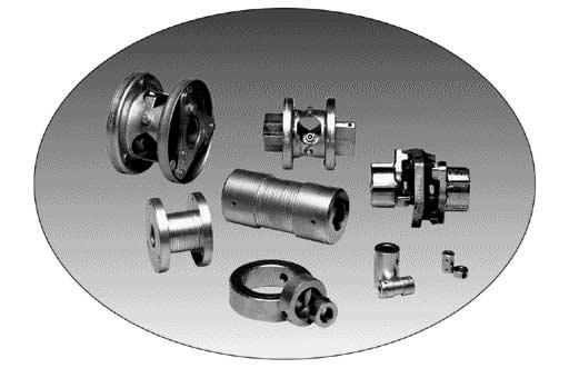
2 Overview Unique Coupling Families Deltaflex The patented Deltaflex series of couplings offer maximum misalignment capabilities with negligible reactionary load, for longer equipment life. This all-metal flex-link coupling requires no lubrication or other maintenance. Typical applications include: compressors, pumps, fans, positioning devices, indexing tables, mixers, papermill roll drives, drive line shafts, turbine drives, wind tunnels, cooling towers, and single bearing generator drives. Uniflex This single piece coupling series solves a variety of application concerns, including high misalignment, space limitations, high temperature and exceptionally low backlash/windup. Typical applications include textile equipment, printing and binding registration, robotics/positioning, conveyors, carton folding and gluing equipment, machine tools, centrifugal pumps, agricultural machinery, blowers, winding machines, and steering mechanisms. Saga The Saga series of couplings offer lower torsional stiffness than any other rubber-in-compression coupling. There is no equal for high shock start/stop applications such as many piston-driven devices, compressors, violent pounding, or crushing units. DELTAFLEX COUPLING UNIFLEX COUPLING Shaft Collars A shaft collar limits the range of travel allowed along the shaft by motor bases, machine tools, and other such items. The precision-machined collars offer ease of installation and the best possible holding strength. Rigid Sleeve Our Rigid Sleeve couplings are suitable for use in joining any two shafts when flexibility is not required. Consisting of a one piece sleeve, the coupling slips onto the ends of the two shafts and is held in place by two set screws. This coupling is best suited for light- to medium-duty applications. SAGA COUPLING SHAFT COLLARS! WARNING You must refer to page iv for Important Safety Instructions and Precautions for the selection and use of these products. Failure to follow the instructions and precautions can result in severe injury or death. RIGID SLEEVE COUPLING -2
3 Overview Deltaflex Coupling Design Lovejoy offers maximum misalignment capacity with the Deltaflex coupling! The Deltaflex coupling is the real solution to installation, misalignment, and performance problems. Conventional couplings even when carefully aligned to the manufacturer s specifications cannot match the low level of vibration, moment of inertia, and additional cushion for future misalignment of a visually aligned Deltaflex coupling. In addition, the Deltaflex coupling gives longer life to equipment shaft bearings. That means longer operating time and reduced maintenance cost. The Deltaflex can handle greater shaft misalignment without generating heavy reaction loads on the equipment shaft bearings. A properly applied and installed Deltaflex coupling offers more equipment protection compared to conventional couplings. Other benefits of the Deltaflex coupling include: n Maximum misalignment capabilities, with negligible reactionary load, for longer equipment bearing life. (see illustrations A, B and C). n Operates as smoothly when misaligned as when perfectly aligned. n No lubrication and no maintenance required. n Equipment can be visually aligned. No special tools are required, which saves on installation time and cost. n Eliminates premature equipment bearing and seal failure resulting from misalignment forces. This means greater equipment productivity. n Torsionally stiff coupling with no backlash means it is capable of high speed applications, within catalog ratings. n Provides long-term performance and economy. n Available in 5 basic sizes, from 10HP to 900HP. n Standard all-metal and stainless steel versions are both available from stock. n Many configurations are available, including shaft-to-shaft, spacer, floating shaft, and special assemblies. TYPE 1 DELTAFLEX COUPLING ILLUSTRATION A MISALIGNMENT CAPABILITY (SIZE 60 ILLUSTRATED) ILLUSTRATION B STANDARD SERIES ILLUSTRATION C HT SERIES Note: 1. Illustrations B and C assume no axial displacement. -3
4 Deltaflex Coupling Design As graphs A and B clearly illustrate, radial load placed on the shaft bearings of the connected equipment by conventional couplings can substantially reduce bearing life and induce detrimental vibration. If the misaligned coupling creates a radial load as can be the case with conventional couplings then nearly 75% of B-10 bearing design life is sacrificed. By using the Deltaflex coupling, B-10 life remains close to 100% of design life, even at maximum misalignment. Because the Deltaflex coupling is designed for infinite fatigue life at maximum angular misalignment at rated torque inadvertent misalignment caused by temperature expansion, equipment frame flexing, foundation movement, environment, etc. will not shorten the life of the coupling or life of the connected equipment. Overview Patented Design Concept*** The concept of the Deltaflex coupling and its misalignment capabilities can be illustrated best when compared to conventional coupling design (see Graphs C and D). Most conventional couplings torque and misalignment capabilities are dependent upon a single flexing member. Soft elastomers are limited by the compressive or tensile strengths of the material. Misalignment is a function and limitation of the material properties and method of connection to the hubs. While other all-metal flexible couplings share the advantage of high torque transmission and better temperature and corrosion resistance, they are typically limited to less than 1 / 2 degree angular with less than inch parallel misalignment. Approaching or exceeding these limits will exert undesired radial loads and vibration on the connected equipment. *** U.S. Patent Number: GRAPH A GRAPH B MAX. (See illustrations B & C on the previous page for specific sizes) GRAPH C GRAPH D -4


5 Overview Deltaflex Coupling Design The Deltaflex Difference In contrast to most conventional coupling designs (see illustration D), the patented Deltaflex coupling is typically arranged in this manner: a hub, a flex-link at each end of a torque sleeve, and a hub (see illustration E). While most conventional coupling designs use a central flexing element, the Deltaflex uses two, making it a double engaging coupling. The patented concept, along with the method of connecting the hubs to the flexible links, permits the tremendous misalignment capabilities without exerting harmful radial loads. The Deltaflex coupling consists of four major components: two delta hubs, an inner flange, and an outer flange. The flex-links, as well as the delta mounting plates, are integral to each flange and are factory assembled. The hub is field-assembled to the flange with three axial cap screws. The two flanges are fastened together radially as the two coupling halves are joined to make a complete coupling. Axial Cap Screws Attaching Hub To Flange Radial Cap Screws (3) Firmly Securing Flanges Into A Rigid Torque Sleeve. In understanding the design of the Deltaflex it is important to note that the inner and outer flanges, once firmly fastened together with three cap screws, become a rigid torque sleeve. The flex links at each end of the torque sleeve accommodate the misalignment generated by the equipment shaft hubs. Typical Deltaflex Applications Use Deltaflex couplings to simplify installation and minimize fabrication costs of structural frames. With the large misalignment capability of Deltaflex, extremely close tolerances will be unnecessary. Typical applications include: compressors, pumps, fans, mixers (vertical and horizontal), turbine drives, wind tunnels, and single bearing generator drives. Some other applications include: 1. Drive-Line Connecting long shaft lines with Deltaflex takes advantage of angular and parallel misalignment capabilities. Permits ease of installation and reduces radial bearing loads to a minimum. 2. Indexing Table or Work Positioning Drive Takes advantage of zero backlash, instant response and constant velocity. Coupling may be between drive motor and gear reduction or on output side of reducer. 3. Cooling Tower Drive The Deltaflex floating shaft coupling permits greater ease of installation with its generous axial misalignment capabilities. Also available in stainless steel. ILLUSTRATION D CONVENTIONAL COUPLING ILLUSTRATION E DELTAFLEX COUPLING INDEXING TABLE COOLING TOWER DRIVE DRIVE-LINE -5
6 Overview Deltaflex Coupling Types The unique design, misalignment capability and simple installation methods make Deltaflex easily adaptable to special applications. Contact Lovejoy Engineering for assistance. Type 1 Shaft to Shaft Hubs Mounted Internally This is the standard arrangement for most shaft to shaft applications. There are five basic coupling sizes in all types, each with a Standard and a High Torque (HT) Series. Both the Standard and the HT Series are dimensionally interchangeable. TYPE 1 ARRANGEMENT Type 2 Shaft to Shaft Hubs Mounted Externally This arrangement is similar to Type 1 in that all components are the same, except the delta hubs are mounted outside the flanges. Type 2A Shaft to Shaft One Hub Mounted Externally, One Hub Mounted Internally One hub mounted on the inside of the flange and one hub mounted on the outside. TYPE 2 ARRANGEMENT Type 3 Spacer Type This arrangement is specifically designed for the pump industry. It is available in a variety of industry standard shaft separations. The shaft center spacer drops out to facilitate easier maintenance of pump parts without disturbing the alignment of pump and motor. Type 4 Floating Shaft Type Type 4 coupling components are the same as Type 3, except that the floating shaft design uses a longer spacer tube to span distances up to 12 feet. Deltaflex floating shaft couplings are light weight, dynamically balanced (as required) and corrosion resistant, which makes them ideal for applications in cooling towers and petrochemical service. TYPE 2A ARRANGEMENT TYPE 3 ARRANGEMENT TYPE 4 ARRANGEMENT -6
7 Selection Process Deltaflex Coupling Selection Step 1: Determine the proper service factor (SF) for the application. This may involve 2 steps: A. Driven equipment service factor (SFa): Select the proper service factor from Chart 1 on page -8. If the application is not listed in Chart 1, use Chart 2. B. When using Chart 1, add the following service factors (SFb) to the values in Chart 1 as required. Add 0.5 for above average torque load variations or start/stop conditions of not more than once per hour. Add 1.0 for reversing loads, start/stop conditions more than once per hour, severe torque load variations or high inertia starting conditions. The additional service factor is added to the Chart 1 service factors to obtain the total service factor. SF = SFa + SFb Step 2: Calculate the equivalent HP/100 RPM. HP/100 RPM = HP* x 100 x SF RPM* * HP and RPM of prime mover. Step 3: Select the Deltaflex size. Method 1: From the coupling selection data (Chart 3 on page -9) select the smallest coupling which is rated equal to or higher than the calculated HP/100 RPM. Method 2: For couplings driven by standard electric motors, you can multiply the HP of the motor by the service factor (SF) and then refer to the electric motor driven chart for selection. Selection Example: A centrifugal fan requires 20 HP, 1,150 RPM motor, direct coupled from the motor to the fan. The motor frame is 286T (1.875 shaft) and the fan shaft is Step 1: Referring to Chart 1, the driven equipment service factor for a centrifugal fan is 1.5 = SFa. The load is uniform and the driver is smooth, therefore SFb is 0. The total service factor SF is = 1.5 Step 2: HP/100 RPM = 20 x 100 x 1.5 = 2.6 HP/100 RPM 1,150 Referring to Chart 3, under the column of HP/100RPM, the smallest coupling you can select is #50 which is rated for 3.0 HP/100 RPM. NOTE: You can also find the coupling size by multiplying SF x 20: SF x 20 = 1.5 x 20 = 30 HP In Chart 3 for motor drives the coupling to select is, again, #50 under 1,150 RPM motors. The size is rated at 34 1,150 RPM. Step 4: Determine the type of Deltaflex needed, e.g., Type 1, Type 2, etc. Step 5: Check limiting conditions. A. Check to be sure that the coupling s Peak Overload Torque Rating is sufficient to accommodate the maximum torque to be transmitted, such as the starting and stall torques of the motor, braking torques and cyclic peak torques, if any. If starting or braking cycles are frequent, the brake torque should be checked against the maximum continuous torque rating of the coupling. T = Tp x SF T = Maximum torque transmitted Tp = Brake torque, starting torque or peak torque SF = Service Factor (determined previously) B. Check the maximum hub bore. If bore size is too large, the next larger size Deltaflex can be specified. C. Check other dimensions such as the limits on shaft sep-aration, hub spacings, space required for the coupling, etc. D. Check maximum speed. If operating speed exceeds 60% of listed maximum speed, the coupling should be dynamically balanced. Step 6. Ordering Information A. Quantity, size, style of couplings. B. Bore and Keyway sizes. C. Dynamic balancing specification, if required. D. Additional non-standard data. 1) Custom mounting dimensions. 2) Between shaft ends (BE) dimension for spacer and floating shaft types. 3) Maximum operating speed for floating shaft couplings. Step 3: In this case, the maximum bore for size #50 coupling is ; therefore, the selection size stands. Step 4: Since this is a shaft-to-shaft application, you will be using the standard Deltaflex coupling Type 1. Determine if any other selection factors apply as described in steps 4 and 5 of the selection guide. Floating Shaft Type Coupling Selection Example Using the preceding data, assume that the shaft spacing from end of shaft to end of shaft is 36(. A floating shaft coupling is then required. The 36 is specified as BE (Between Ends) = 36. Refer to the Type 3 and 4 Chart to find the overall length of the coupling; add dimension 2 x LTB to BE. For a size #50 type 3, the overall length will be x 1.69 = Note that the length of the spacer tube assembly will be 36-2R = = This is the amount of space, or dropout section, between the fixed portions of the coupling. -7
8 Selection Process Deltaflex Coupling Service Factors Chart 1 Typical Service Factors Electric Motor and Turbine Driven Equipment Agitators Liquids Variable Density Blowers Centrifugal Lobe Vane Car Dumpers Car Pullers Clay Working Machinery Compressors Centrifugal Lobe, Vane, Screw Reciprocating Multi-cylinder...Not Recommended Conveyors Uniformly Loaded Or Fed Conveyors Heavy Duty Not Uniformly Fed Conveyors Vibratory Cranes and Hoists...Not Recommended Crushers Extruders Plastic Metal Fans Centrifugal Axial Mine Ventilation Cooling Towers Light Duty Blowers & Fans Feeders Light Duty Heavy Duty Food Industry Cereal Cooker Dough Mixer Meat Grinder Can Filling Machine Bottling Generators Non-Welding Welding Hammer Mills Lumber Industry Barkers Drum Type Edgar Feed Live Rolls Log Haul Incline Log Haul Well Type Planer Feed Chains Planer Floor Chains Planer Tilting Hoist Slab Conveyor Sorting Table Trimmer Feed Machine Tools Bending Roll Punch Press Gear Driven Tapping Machines Auxiliary Drives Metal Mills Draw Bench Carriage Draw Bench Main Drive Forming Machines Slitters Table Conveyors Non-Reversing Reversing Wire Drawing & Flattening Machine Wire Winding Machine Mills, Rotary Type Ball Cement Kilns Dryers & Coolers Kilns Pebble Rod Tumbling Barrels Mixers Concrete Mixers Drum Type Oil Industry Chillers Oil Well Pumping Rotary Kilns Paper Mills Barker Auxiliaries, Hydraulic Barker Mechanical Barker Drum (Spur Gear Only) Beater & Pulper Bleacher Calenders Cylinders Dryers Jordans Log Haul Presses Suction Roll Washers and Thickeners Winders Printing Presses Pumps Centrifugal General Duty (Liquid) Boiler Feed Slurry (Sewage, etc.) Dredge Reciprocating... Double Acting...Not Recommended Single Acting...Not Recommended Rotary Gear, Lobe, Vane Rubber Industry Mixer Banbury Rubber Calender Rubber Mill (2 or more) Sheeter Tire Building Machines Tubers and Strainers Screens Rotary Stone or Gravel Traveling Water Intake Vibratory Sewage Disposal Equipment Textile Industry Batchers Calenders Card Machines Dry Cans Dryers Dyeing Machinery Looms Mangles Soapers Spinners Windlass Chart 2 Service Factors for Driven Equipment Load Classifications Note: -8 * indicates that torque load reversal can exist without reversing rotation and can be caused by overrunning the load with inertia or shifting of the load. Consult Lovejoy Engineering.
9 Performance Data Deltaflex Coupling Ratings Chart 3 HP and Torque Ratings Size Maximum Bore Delta Hub Round Hub inch mm inch mm Maximum Continuous Torque Peak Overload Torque in-lbs Nm in-lbs Nm HP Rating 1 Motor RPM RPM 875 1,150 1,750 3, , HT , , , , HT , , , , HT , ,000 1, ,500 1,073 14,250 1, HT ,000 1,695 22,500 2, ,900 2,587 34,500 3, , HT ,000 3,728 49,500 5, ,832 Note: 1. The HP ratings listed are for drives with a Service Factor of 1.0 (refer to Chart 1 for Service Factors). Further, the ratings are based on prime movers such as electric motors or turbines. HP/100RPM = HP x 100 RPM T(Torque) = HP x 63,025 RPM HP = Tx RPM 63,025 Internal Combustion Engines Deltaflex couplings are not recommended for direct connection to internal combustion engine drives. -9
10 Deltaflex Coupling Data Type 1 Shaft to Shaft Hubs Mounted Internally This is the standard arrangement for most shaft to shaft applications. There are five basic coupling sizes in all types, each with a Standard and a High Torque (HT) Series. Both the Standard and the HT Series are dimensionally interchangeable. Type 1 features the standard inner and outer flanges and delta hubs, which are triangular in shape to accommodate the delta flex-link pattern. The standard flanges are stamped steel, while the flex links in all Deltaflex couplings are precipitation-hardened (PH 17-7) stainless steel. Delta hubs are ductile iron, zinc clear dichromate-plated and available from stock in a variety of bore sizes. Every Deltaflex hub is standard with two set screws at 120º. Hub to flange (axial) and flange to flange (radial) hardware is SAE Grade 5. Stainless steel flanges with standard ductile iron delta hubs are available from stock as an option. Delta style hubs are not available in stainless steel. Type 1 Shaft to Shaft Hubs Mounted Internally Max. Min. RSB 1 Size inch mm inch mm Notes: Bores OD OAL C G inch inch inch inch HP/100 RPM Max. Cont. Torque in-lbs Nm 1. RSB hubs are furnished with two set screws at 120º, no keyway. 2. Peak Overload Torque = Torque that can be applied for short periods, such as shock loads, start up, etc. 3. See illustrations B & C on page -3 for combined maximum misalignment. 4. Axial Freedom is provided only for the purpose of system expansion or due to temperature changes or shaft flotation (such as with sleeve bearing motors). 5. Balancing is not required below 60% of Maximum RPM. Peak Overload Torque 2 Axial in-lbs Nm Angular 3 Parallel 3 Freedom 4 WR 2 lbs-in , º ,000 40HT , , º , , , º ,000 50HT , , º , , , º ,000 60HT , ,000 1,017 5º , ,500 1,073 14,250 1,610 6º ,000 80HT ,000 1,692 22,500 2,542 5º , ,900 2,587 34,500 3,898 6º , HT ,000 3,728 49,500 5,593 5º ,000 LTB OAL2 Max. RPM Type 2 Shaft to Shaft Hubs Mounted Externally This arrangement is similar to Type 1 in that all components are the same, except the delta hubs are mounted outside the flanges. An optional version of the Type 2 uses round hubs mounted externally on both ends or on one end to accommodate larger bore requirements. Type 2 is available as a stock option with stainless steel flanges and stainless steel round hubs. Delta style hubs are not available in stainless steel. See next page for dimensions. HD OD -10
11 Deltaflex Coupling Data Type 2A Shaft to Shaft One Hub Mounted Externally, One Hub Mounted Internally One hub is mounted on the inside of the flange and one hub is mounted on the outside. Round hubs cannot be mounted on the inside of the coupling. Type 2A is available as a stock option with stainless steel flanges. The internal hub would be ductile iron, while the external hub would be a stainless steel round hub. Delta hubs are not available in stainless steel. Type 2 and 2A Shaft to Shaft Hub(s) Mounted Externally Min. Bore 1 Delta Hub Round Hub Delta Hub inch mm inch mm inch mm Max. Cont. Torque Peak Overload Torque Size inch inch inch inch inch inch inch RPM in-lbs Nm in-lbs Nm RPM , ,000 40HT , , , , , ,000 50HT , , , , , ,000 60HT , ,000 1,017 5, ,500 1,073 14,250 1,610 4,000 80HT ,000 1,695 22,500 2,542 4, ,900 2,587 34,500 3,898 3, HT ,000 3,728 49,500 5,593 3,000 Notes: Max. Bore OD OAL1 2 OAL2 2 G1 3 G2 3 HD LTB HP/ Min. bore hubs are furnished with two set screws at 120º, no keyway. 2. OAL1 is overall length with one hub mounted externally; OAL2 is with both hubs mounted externally. 3. G1 is hub gap with one hub mounted externally; G2 is with both hubs mounted externally. 4. For misalignment capabilities, see illustrations B and C on page -3, or Type 1 data on previous page. See page -9 for Performance Data. Max. Type 3 Spacer Type This arrangement is specifically designed for the pump industry and is available in a variety of industry standard shaft separations. The shaft center spacer drops out to facilitate easier maintenance of pump parts without disturbing the alignment of pump and motor. Spacer type couplings utilize either standard delta hubs or optional round hubs. The center member of the Deltaflex is captured by the construction of the spacer flanges for greater safety. Standard spacer drop out lengths are available to accommodate shaft separations of 3.50, 4.38, 5, 7, 10, 12 and 15 inches. Special spacer lengths and stainless steel spacer couplings are available as an option. Type 4 Floating Shaft Type The Type 4 coupling components are identical to Type 3, except the floating shaft design uses a longer spacer tube to span distances up to 12 feet. Deltaflex floating shaft couplings are lightweight, dynamically balanced (as required) and corrosion resistant. The center member of the Deltaflex is captured by the construction of the spacer flanges for greater safety. Floating shaft couplings are also available in stainless steel. See next page for dimensions. Floating Shaft Coupling Maximum Parallel Misalignment Dimensions in Inches at Max. RPM Size 1, HT HT HT HT HT
12 Deltaflex Coupling Data 2500 Speed In RPM Balancing May Be Required Depending On Application Dynamic Balancing Of Center Member Required, Consult Lovejoy. Type 3 and 4 Spacer and Floating Shaft BE < 18" = Spacer coupling (Type 3); BE > 18" = Floating Shaft coupling (Type 4) 500 Balancing Not Required Floating Shaft Couplings Balancing Requirements Max. Bore Min. Bore 1 Delta Hub Round Hub Delta Hub OD HD LTB 4 D R S 3 HP/100 Torque Torque Size inch mm inch mm inch mm inch inch inch inch inch inch RPM in-lbs Nm in-lbs Nm See , HT Chart 2.0 1, , for 3.0 1, , HT Type , , Below 6.5 4, , HT , ,000 1, ,500 1,073 14,250 1,610 80HT ,000 1,695 22,500 2, ,900 2,587 34,500 3, HT ,000 3,728 49,500 5,593 Max. Cont Peak Overload Notes: 1. Minimum bore hubs are furnished with 2 set screws at 120º, no keyway. 2. BE is the distance between the ends of equipment shafts please supply this dimension when placing orders, BE = OAL-2 (LTB), BE = S + 2 (R) 3. S is the Spacer drop out or floating shaft length, S = BE-2(R). 4. LTB is the length through the hub bore. OAL is the overall length, OAL = BE + 2(LTB) Type 3 Standard Spacer Drop Out Assemblies BE S OAL Size inch mm inch mm inch mm Type 4 Floating Shaft Coupling Maximum Span Inch Max. Span - BE Size 1,750 RPM 1,150 RPM 875 RPM 40/40HT /50HT /60HT /80HT /100HT Note: 40/40HT /50HT /60HT /80HT /100HT Consult Lovejoy Engineering for other RPM/Span applications. -12
13 Deltaflex Coupling Data DELTA HUB ROUND HUB Delta Hub and Round Hub Max. Bore Min. Bore Axial Cap Delta Hub Round Hub Delta Hub HD LTB BC Q P Screw Tap Size inch mm inch mm inch mm inch inch inch inch inch TH Set Screw 40/40HT / /4-20 x.62 1 / /50HT / /16-18 x.75 1 /4-20* 60/60HT / /8-16 x.88 3 / /80HT / /2-13 x / /100HT / /8-11 x /2-13 Notes: 1. * indicates in some bore sizes the tap is 5 / Maximum Bores are provided with standard keyway. RSB hubs do not have a keyway. Both Delta hubs and Round hubs are provided with two set screws at 120º. Deltaflex Standard Bore Availability Chart Size /40HT D S S S S S S S R R N/A N/A N/A 50/50HT D S S S S S S S S S S S R 60/60HT N/A N/A D S S S S S S S S S S 80/80HT N/A N/A N/A N/A N/A N/A N/A D N/A S S S S 100/100HT N/A N/A N/A N/A N/A N/A N/A N/A N/A N/A D S S Size /40HT N/A N/A N/A N/A N/A N/A N/A N/A N/A N/A N/A N/A 50/50HT R R N/A N/A N/A N/A N/A N/A N/A N/A N/A N/A 60/60HT S S S S R R R R N/A N/A N/A N/A 80/80HT S S S S S S S S S S S S 100/100HT S S S S S S S S S S S S Size /40HT N/A N/A N/A N/A N/A N/A N/A N/A N/A N/A N/A N/A 50/50HT N/A N/A N/A N/A N/A N/A N/A N/A N/A N/A N/A N/A 60/60HT N/A N/A N/A N/A N/A N/A N/A N/A N/A N/A N/A N/A 80/80HT R R R R N/A N/A N/A N/A N/A N/A N/A N/A 100/100HT S S S S S S R R R R R R Notes: 1. S indicates Standard hub, finished bores available from stock, two set 120º and standard keyway. 2. R indicates Round hub, finished bores available from stock, two set 120º and standard keyway. 3. D indicates Delta hubs, rough stock bores available from stock, two set 120º, no keyway. 4. N/A indicates not available -13
14 Overview Uniflex Coupling Design Flexible Spring Type Coupling with Exclusive Triple Wound Spring Design The Uniflex Coupling is an all steel, single piece coupling that solves a variety of application concerns including: high misalignment, space limitations, high temperature, and exceptionally low backlash/windup. The unique flexing center of the Uniflex consists of three opposingly wound square wire springs for forward or reverse operation. Two steel hubs are then brazed to the steel spring pack to create a durable one-piece flexible coupling. Benefits of this coupling include: UNIFLEX TRIPLE RING COUPLING n n n n n This designed flexibility compensates for high degrees of shaft misalignment (up to 4.5º angular, up to.045" parallel). The one piece Uniflex is simple to install nothing to replace, no wearing parts, and no lubrication needed. The compact design provides a coupling that is smaller and lighter than most couplings of comparable torque ratings. It is also well suited for applications with inaccessible mounting locations. All metal design means that the Uniflex can be used in applications where severe environmental concerns are a factor. Standard couplings withstand temperatures to +250º F (due to soldering); special designs to +600º F (stainless steel w/electron beam weld). The Uniflex is unaffected by oil, grease, dirt and most industrial chemicals. The Uniflex is designed for applications up to 30,000 RPM such as textile equipment, conveyors, machine tools, centrifugal pumps, blowers, winding machines, and steering mechanisms. In addition, most sizes can be supplied in stainless steel for applications requiring frequent washdowns (food processing), additional chemical resistance (salt water handling), non-magnetic properties (military), or sterile/vacuum usage (pharmaceutical). Uniflex Coupling Types Four styles of Uniflex couplings are available: shaft-to-shaft, drop out, flange-to-flange and flange-to-shaft. U Type This is a durable one-piece flexible coupling for general purpose shaft-toshaft applications. It is the basis for all Uniflex coupling types. U TYPE RRU Type This design offers quick disconnect for drop out requirements. It can also accomodate a slightly larger shaft diameter than the standard U type. UF Type This flange-to-flange type is designed to connect flange mounted equipment to another flange while compensating for misalignment. It is also the center drop out section of the RRU type. UFH Type A flange-to-shaft configuration, this couples flange mounted equipment to a shaft with all the benefits of Uniflex versatility. The stock flange plate is the same as used on the UF type. RRU TYPE UF TYPE -14 UFH TYPE
15 Selection Process Uniflex Coupling Selection Once it is determined that the unique features of Uniflex meet your application, selection of the proper coupling depends on three factors: torque transmission, bore requirements, and RPM. When selecting a Uniflex coupling, the torque capability shown as maximum must not be exceeded. Nominal torque adjusted by an application service factor, start up torque, braking torque and any cyclic shock or peak torques inherent in the application must be considered. Determine the correct Uniflex coupling size by working out the following calculations: Step 1: Determine the Uniflex type or configuration from page -14. Step 2: Calculate the nominal torque as T or nominal HP/100RPM T = (HP* x 63,025) HP/100RPM = HP* x 100 (in-lbs) RPM* RPM* Step 3: Determine the application service factor from page JW-6. Multiply the nominal torque by the application service factor to determine the total required torque. Step 4: Select the size. Step 5: Check to be sure the peak torque or maximum torque from starting, braking or cyclic peaks does not exceed the coupling maximum capability. For applications involving frequent starts and stops, refer to Lovejoy Engineering. NOTE: Diesel and gasoline engine drives usually require special considerations. Refer to Lovejoy Engineering. Step 6: a.check the coupling maximum bore capability versus the shaft to be used. If necessary, pick a larger size coupling to get the needed bore capacity. b.check the maximum speed. c. Check any limiting dimensions. T = (KW* x 9,550) (Nm) RPM * Usually HP (KW) & RPM of prime mover, if the coupling is to be attached to the prime mover or if no speed or torque devices are between the driver and driven equipment. Selection Example A rolling device operates at 6,000 RPM and requires 15 HP. The driving shaft is diameter and the roll shaft is diameter. Select the proper U type shaft-to-shaft coupling. Occasional emergency stops impose 675 in-lbs of torque, otherwise the operation has no cyclic loading. Start up torque is 1 / 3 of emergency stopping torque. Rolls of various types typically have a application service factor. Determine the nominal torque or HP/100RPM: Step 3: The U-125 has a maximum bore capability of 1.250, which covers the application driver shaft of the same size. The roll shaft is 1.125, which is less than maximum. Note: Uniflex maximum bore sizes includes a standard keyway allowance. Step 1: T= 15 x 63,025 = 158 in-lbs 6,000 HP/100 RPM = 15 x 100 = 0.25 HP/100 RPM 6,000 Step 2: Determine the Total Rated Torque: Tr = 158 x 2.0 = 316 in-lbs Maximum stopping torque = 675 in-lbs Start up torque = 225 in-lbs The U-125 coupling meets all the above requirements with the key item as the maximum stopping torque. -15
16 Performance Data Uniflex Coupling Technical Data Selection Chart Misalignment Capability Wind Up Maximum Maximum At Max. Maximum Parallel Recommended Maximum Maximum Size Torque 1 Angular Offset End Play Torque HP Speed Offset in mm in mm in-lbs Nm 100RPM RPM 18 Reg. 1.80º 3.0º , Reg. 1.80º 4.5º , Reg. 1.78º 4.5º , Reg. 1.82º 4.5º , Reg. 0.85º 3.0º , Reg. 1.82º 4.5º , Reg. 1.68º 4.5º , Reg. 1.03º 3.0º , Reg. 1.85º 4.5º , Reg. 1.85º 3.0º , , Reg. 0.85º 3.0º , , Short 1.07º 3.0º , Short 1.09º 3.0º , Short 1.05º 3.0º , Short 0.85º 3.0º , Short 1.12º 3.0º , Short 1.17º 3.0º , Short 1.03º 3.0º , Short 1.22º 3.0º , Short 1.35º 3.0º , , Short 0.85º 3.0º , ,000 Notes: 1. Total backlash is approximately 1 / 3 of windup at maximum torque consult Lovejoy Engineering for more information. 2. See Lovejoy list pricebook for UPC numbers. -16
17 Uniflex Coupling Data U Type Shaft-to-Shaft The U type is the basis for all Uniflex couplings. It is a shaft-to-shaft flexible coupling with a simple one piece design, making it ideal for indexing, robotic or positioning applications. The U type consists of a triple-wound flexible steel spring brazed to a steel hub at each end. This all steel design ensures optimum equipment protection in severe environments and/or high temperature applications. U TYPE Regular and short versions are available for most sizes to accommodate different overall length requirements. Special hub or bore modifications are also possible. These units can be supplied with either pin holes or with keyways and set screws. Lovejoy does not recommend the reboring of uniflex couplings by customers due to potential damage to the brazed joint. U Type Pin Min. Max. LTB OAL 1 Location (SL) Pin Set Screw Size HD Bore Bore Reg Short Reg Short Reg Short Size Qty Per Weight in in mm in mm in in in in in in in Hub Size lbs. kg. U / U / U / U /8 1 1 / U /8 1 1 / U /8 1 1 / U / / U / / U / / U /8 1 3 / U /8 1 3 / Note: 1. OAL Tolerance + 1 / 8 inch. Stainless Steel U Series Max. Pin Bore LTB OAL 1 Location (SL) Pin Set Screw Weight Size HD in mm Reg Short Reg Short Reg Short Size Qty Per lbs kg. in in in in in in in Hub Size U / U / U / U /8 1 1 / U /8 1 1 / U /8 1 1 / U / / U / / U / / Note: 1. OAL Tolerance + 1 / 8 inch. -17
18 Uniflex Coupling Data RRU Type Dropout Style The RRU type Uniflex coupling is designed for fast, easy installation and removal without disrupting the connected shafts. This is ideal when servicing impellers, bearings and seals. The design consists of two steel hubs fastened with cap screws to a Uniflex double flange coupling (UF type). The RRU is easily disassembled by simply removing the cap screws and sliding out the UF center spring section. RRU TYPE UF Type Flange-to-Flange This coupling is actually the center dropout section of the RRU type, but it can be purchased separately for direct flange-to-flange mounting of the driving unit to the driven. The UF type coupling compensates for high misalignment to protect connected equipment, yet it is also well-suited for applications which require negligible backlash or windup and reliability under high temperature conditions. Stock flange sizes are shown in the table below, but other sizes can be provided to meet special mounting requirements. UF TYPE RRU and UF Types Min. Max. Pin Loc. Pin HD Bore Bore HL FL FL1 OAL 1 D FD SL Size S 2 BC Mtg. Screw 3 Set Screw Size in in. mm in. mm in in in in in in in in in in Qty. Size Qty. Size RRU / / /4-20 RRU / / /4-20 RRU / / /4-20 RRU / / /4-20 RRU / / /8-16 RRU / / /8-16 RRU / / /8-16 Notes: OAL Tolerance +.19 inch. 2. UF Center Drop out Length Tolerance +.12 inch. 3. Screws not supplied for UF. 4. When ordering specify prefix RRU or UF; dimensions remain the same for either. 5. See page -16 for Performance Data.

19 Uniflex Coupling Data UFH Type Flange-to-Shaft The one-piece UFH type coupling is similar to the U type, except that one hub is replaced by a flange plate. Stock flange sizes are shown in the table below but other sizes can be made to order. As with the other Uniflex styles, this coupling compensates for high degrees of angular and parallel misalignment with very little backlash or windup and is reliable in harsh or severe environments. Regular and short versions are available for each size to accommodate different overall length requirements. For increased versatility, the hub can be modified with a tapered, spline, hex or square bore. The standard hub is furnished with either a pre-drilled pin hole or with a keyway and set screw. Specify when ordering. UFH TYPE UFH Series Min. Max. LTB OAL 1 Pin Loc. Pin Size HD Bore Bore Reg Short FL1 Reg Short FD D SL Size BC Mtg. Screw 2 Set Screw in in mm in mm in in in in in in in in in in Qty. Size Qty. Size UFH / / /4-20 UFH / / /4-20 UFH / / /4-20 UFH / / /4-20 UFH / / /8-16 UFH / / /8-16 UFH / / /8-16 Notes: 1. OAL Tolerance +.12 inch. 2. Screws not supplied. 3. See page -16 for Performance Data. -19


20 Overview Saga Coupling Design Elastomeric Pre-compression Type Saga is a general purpose, torsionally soft coupling with high tolerance to all forms of misalignment. The design features hexagonal or octagonal rubber donut-shaped elements with metal inserts positioned at each apex during the vulcanization process. These metal inserts carry actual bolts which fix the element to tines on cast, cylindrical hubs. Embedded inserts also have tines which connect with mating surfaces on hubs so that axial bolts can be easily torqued during assembly without twisting the rubber beyond the limits of its elasticity. The rubber between each apex is precompressed, so it is much more durable to the stresses arising from the various forms of misalignment and torsional vibrations. While the Saga coupling is normally associated with shaft-to-shaft applications, adaptations for flange and flywheel mountings can be made. In addition, a floating shaft version for use in lieu of a u-joint drive shaft with separate torsional coupling is available. Its elements can also be stacked in series for use in applications with extreme transient or permanent parallel misalignment, or where torsional dynamics demand an extremely soft element for proper damping and/or vibratory decoupling. The rubber s stiffness of 60 as measured against Shore A by durometer, covers the majority of such situations. Performance benefits of this coupling include: n No end thrust in misalignment position. n Absorbs misalignment and shock. n No axial reaction force to damage or accelerate wear in system bearings. n Accepts constant angular misalignment of up to 3º n Parallel tolerance of 0.060( (1.5mm), while reaction force remains low. n Lateral softness without complication, or sacrifice of performance or durability. n Natural rubber can operate in temperatures from -60º to +200º F (-51º to 93º C). Note: For applications requiring simultaneous angular and parallel misalignment, consult Lovejoy Engineering to ensure that heat generated from all three forms of stress do not exceed the coupling s ability to dissipate heat. Selection Process Step 1: Establish torque or HP rating of the driver and operating and maximum RPM (for electric motors, these are essentially the same). Step 2: Determine the horsepower 100RPM: HP x 100 = HP per 100 RPM RPM or establish driver torque at operating RPM. SAGA TYPE ANGULAR OFFSET (EXAGGERATED) PARALLEL OFFSET (EXAGGERATED) Step 3: Using the service factor selected from the table on JW-6, multiply torque or HP/100 RPM by the factor. Using the result, select a coupling from the Performance Data chart on the next page. The coupling s rating must be equal to or greater than adjusted HP/100RPM or torque. Step 4: Compare the maximum driver RPM to the Performance Data chart on the next page to insure that the coupling s speed limit is not exceeded. Step 5: Finally, determine shaft diameters of both driving and driven equipment and check them against maximum bore diameters from the chart on the next page to ensure that these values are not exceeded. -20
21 Saga Coupling Data Performance Data Dynamic HP/100 RPM Rated Torque Max. Torsional Specific Max. Approx. Moment of for 1.0 for 1.0 S.F. Shock Load Stiffness Torsional Speed Weight Inertia WR 2 Size service factor in-lbs Nm in-lbs Nm in-lbs/deg in-lbs/rad Stiffness RPM 1 lbs kg. lb in 2 S , , , S , , , S , , , , S , , , , S , , , , S , , , , S , , , , S , , , , , S , , , , , ,200.0 Note: 1. For higher speeds, balancing may be necessary. Bolt Data Bolt Rec. Tightening Grade No. 5 Torque of Bolts Size T Wet Dry Qty. Size ft-lb Nm ft-lb Nm S-11 6 ⁵ ₁₆ - 18 x 1³ ₄ S-13 6 ³ ₈ - 16 x S-15 6 ³ ₈ - 16 x 2 ¹ ₂ S-18 6 ¹ ₂ - 13 x S-22 6 ⁵ ₈ - 11 x 3 ¹ ₄ S-26 6 ³ ₄ - 10 x S-30 6 ³ ₄ - 10 x 4 - ¹ ₂ S-34 8 ³ ₄ - 10 x 4- ¹ ₂ S x 5 - ¹ ₂ Rough Max Stock Bore 2 Bore B B OAL OD HD W LTB BC Dia. D L Size in mm in. mm in in in in in in in in S S S S S S S S S Note: 2. Standard bores available by 1 / 16 increments. Some metric sizes also available as standard. -21
22 Rigid Sleeve Couplings Lovejoy Rigid Sleeve couplings fit the standards of the industry. These couplings, the simplest type, provide a fixed union between two shafts which are precisely aligned. They are suitable for use in joining any two shafts when flexibility is not required, shaft alignment is maintained and proper bearing support is provided. Bore tolerances are -.000/ RIGID SLEEVE COUPLING Rigid Sleeve Couplings Set Screw Item OD OAL SL T Bore Size (UPC) No. in in in in in SC x 1 / * SC x 1 / * SC x 3 / * SC /4-20 x 3 / SC /16-18 x 1 / SC /16-18 x 5 / SC /16-18 x 5 / SC /8-16 x 3 / SC /8-16 x 3 / SC /8-16 x 3 / SC /8-16 x 3 / Note: * indicates that these sizes do not have keyways -22

23 Shaft Collars Zinc Plated and Stainless Steel Lovejoy shaft collars are precision machined for the best possible fit. Standard steel collars are made from highest quality cold finished steel bar stock and zinc plated for corrosion resistance and outstanding appearance. Stainless steel collars are made from type 303 stainless and include a stainless steel set screw. All Lovejoy shaft collars use socket cup point set screws for ease of installation and best possible holding strength. Made in USA. Selection & Item (UPC) numbers Bore 2 Size Zinc Plated Stainless OD W Set Screw 1 /8 LSC x 1 / 8 3 /16 LSC x 1 / 8 1 /4 LSC x 1 / 8 5 /16 LSC x 3 / 16 3 /8 LSC /4-20 x 3 / 16 7 /16 LSC /4-20 x 1 / 4 1 /2 LSC /4-20 x 1 / 4 9 /16 LSC /4-20 x 1 / 4 5 /8 LSC /16-18 x 1 / 4 11 /16 LSC /16-18 x 1 / 4 3 /4 LSC /16-18 x 1 / 4 13 /16 LSC /16-18 x 1 / 4 7 /8 LSC /16-18 x 5 / /16 LSC /16-24 x 1 / 4 1 LSC /16-24 x 1 / / 16 LSC /16-18 x 5 / / 8 LSC /16-18 x 5 / / 16 LSC /8-16 x 3 / / 4 LSC /8-16 x 3 / / 16 LSC /8-16 x 3 / / 8 LSC /8-16 x 3 / / 16 LSC /8-16 x 3 / / 2 LSC /8-16 x 3 / / 16 LSC /8-16 x 3 / / 8 LSC /8-16 x 3 / / 16 LSC /8-16 x 3 / / 4 LSC /2-13 x 1 / / 16 LSC /2-13 x 1 / / 8 LSC /2-13 x 1 / / 16 LSC /2-13 x 1 / 2 2 LSC /2-13 x 1 / / 16 LSC /2-13 x 1 / / 8 LSC /2-13 x 1 / / 16 LSC /2-13 x 1 / / 4 LSC /2-13 x 1 / / 16 LSC /2-13 x 1 / / 8 LSC /2-13 x 1 / / 16 LSC /2-13 x 1 / / 2 LSC /2-13 x 1 / / 16 LSC /2-13 x 1 / / 8 LSC /2-13 x 1 / / 16 LSC /2-13 x 1 / / 4 LSC /2-13 x 1 / / 16 LSC /2-13 x 1 / / 8 LSC /2-13 x 1 / / 16 LSC /2-13 x 1 / 2 3 LSC /2-13 x 1 / 2 Notes: 1. When referencing the Lovejoy UPC number, include as a prefix to the number shown in the chart above. 2. Bore Tolerance LSC-2 through LSC-16, Bore Tolerance LSC-17 through LSC-48,
Specialty Couplings. Overview. Deltaflex Coupling Design Lovejoy offers maximum misalignment capacity with the Deltaflex coupling! SP-3.
 Overview Deltaflex Coupling Design Lovejoy offers maximum misalignment capacity with the Deltaflex coupling! The Deltaflex coupling is the real solution to installation, misalignment, and performance problems.
Specialty Products. In This Section: Deltaflex Uniflex Saga Rigid Sleeve Shaft Collars. SP-1
 JW Specialty Products In This Section: Deltaflex Uniflex Saga Rigid Sleeve Shaft Collars www.lovejoy-inc.com 301-1 JW Specialty Products Safety Warning When using Lovejoy products, you must follow these
Gear Coupling. Applications
 Gear Coupling Applications Power Transformation Print & Paper Industries Gear Boxes Textile Industries Conveyors Pumps Compressors Process, Chemical & Pharmaceutical Industries Nylon Gear Couplings Nylon
Universal Joints. In This Section: D Type HD Type D Type Stainless NB (Needle Bearing) Type LOJ Type DD and DDX Type Universal Joint Boots
 Type LOJ Type DD and DDX Type Universal Joint Boots") JW Universal Joints In This Section: D Type HD Type D Type Stainless NB (Needle Bearing) Type LOJ Type DD and DDX Type Universal Joint Boots www.lovejoy-inc.com 329-1 JW Universal Joints Safety Warning
JW Universal Joints In This Section: D Type HD Type D Type Stainless NB (Needle Bearing) Type LOJ Type DD and DDX Type Universal Joint Boots www.lovejoy-inc.com 329-1 JW Universal Joints Safety Warning
Power Transmission Products. Maurey Couplings. Hi-Flex Tire Couplings Hi-Q Jaw Couplings Finished Bore Sleeve Couplings Rigid Bushed Sleeve Couplings
 Power Transmission Products Maurey Couplings Hi-Flex Tire Couplings Hi-Q Jaw Couplings Finished Bore Sleeve Couplings Rigid Bushed Sleeve Couplings Hi-Q Flexible Couplings R to enable full power transmission
FLEXIBLE JAW COUPLINGS
 To order this part, call Lifco Hydraulics USA Toll Free at -800-92-849 Jaw Type Couplings USA Standard The Jaw Type Couplings from Vescor are offered in the industry s largest variety of stock bore/keyway
Jaw Type. Overview. Jaw Type Couplings USA Standard Elastomer-in-Compression
 -1 Overview Jaw Type Couplings USA Standard Elastomer-in-Compression The Jaw Type couplings from Lovejoy are offered in the industry s largest variety of stock bore/keyway combinations. These couplings
Jaw. In This Section:
 Jaw In This Section: L Type LC Type Al Type - Aluminum SS Type - Stainless RRS and RRSC Types - Spacer C and H Type - Medium / Heavy Duty RRC Type - Spacer www.lovejoy-inc.com 13-1 Jaw Safety Warning When
Jaw Type JW JW-1. Polígono Indutrial O Rebullón s/n Mos - España -
 -1 Overview Couplings USA Standard Elastomer-in-Compression The couplings from Lovejoy are offered in the industry s largest variety of stock bore/keyway combinations. These couplings require no lubrication
L-Jaw Elastomeric Couplings
 L-Jaw Elastomeric Couplings F3 100% interchangeable with industry standard 3 Insert materials available 3 Hub materials available Large selection of sizes P-1686-TBW 4/16... TB Wood s 888-829-6637 F3-1
Jaw In-Shear Type JIS JIS-1
 -1 Overview 6 Pin Saves Great Amounts Of Time, Maintenance, And Inventory Costs Lovejoy s commitment to continual product improvement is demonstrated in the next generation of the Jaw In-Shear () coupling
Jaw. In This Section:
 Jaw In This Section: L Type LC Type Al Type - Aluminum SS Type - Stainless RRS and RRSC Types - Spacer C and H Type - Medium / Heavy Duty RRC Type - Spacer www.lovejoy-inc.com 13-1 Jaw Safety Warning When
Size 1120, Bore Ø0.75" Size 1320, Bore Ø1.25" Size 1420, Bore Ø1.375" 3/4HP. Size 1320, Bore Ø1.25" Size 1320, Bore Ø1.25" Size 1633, Bore Ø2.
 Product Range Hollow Shaft Type Selections shaded in blue offer an increased service factor. Please refer to the gearmotor selection tables for specific unit service factor details. Nominal Ratio (:1)
Jaw In-Shear 6 Pin Reduces Downtime, Maintenance, And Inventory Costs
 Jaw In-Shear 6 Pin Reduces Downtime, Maintenance, And Inventory Costs Lovejoy's commitment to continual product improvement is demonstrated in the next generation of the Jaw In-Shear (JIS) coupling - the
Thomas Flexible Disc Couplings (Metric)
") Disc Catalog Download most up-to-date versions at www.rexnord.com Thomas Flexible Disc s (Metric) Table Of Contents DESCRIPTION PAGE Application Guide................................................................................................................
Disc Catalog Download most up-to-date versions at www.rexnord.com Thomas Flexible Disc s (Metric) Table Of Contents DESCRIPTION PAGE Application Guide................................................................................................................
(d) Bore Size Check from Dimensions table (page 112) that chosen flanges can accommodate required bores.
 Bore Size Check from Dimensions table (page 112) that chosen flanges can accommodate required bores.") Fenaflex Couplings The Fenaflex coupling is a highly flexible, torsionally elastic coupling offering versatility to designers and engineers with a choice of flange combinations to suit most applications.
Fenaflex Couplings The Fenaflex coupling is a highly flexible, torsionally elastic coupling offering versatility to designers and engineers with a choice of flange combinations to suit most applications.
Clutch Couplings FW/FWW. Overrunning Ball Bearing Supported, Sprag Clutch Couplings. FW Series. FWW Series. Typical Applications
 s Overrunning Ball Bearing Supported, Sprag s Series For in-line shaft applications Outer race overrunning intermediate speed Inner race overrunning high speed clutch couplings are comprised of an FSO
Thomas Flexible Disc Couplings (Inch)
") Disc Catalog Download the most up-to-date version at www.rexnord.com/documentation Thomas Flexible Disc s (Inch) Table Of Contents DESCRIPTION PAGE Application Guide................................................................................................................
Disc Catalog Download the most up-to-date version at www.rexnord.com/documentation Thomas Flexible Disc s (Inch) Table Of Contents DESCRIPTION PAGE Application Guide................................................................................................................
PRODUCT MANUAL TYRE-FLEX COUPLING (T,TO & RST)
") RATHI TRANSPOWER PVT. LTD. PUNE - INDIA PRODUCT MANUAL TYRE-FLEX COUPLING (T,TO & RST) R-PM-T-1/3-1/14 Page 1 INDEX CONTENTS PAGE Standard Features 3 At a Glance 3 TYRE-FLEX Family 3 Elastomer Information
RATHI TRANSPOWER PVT. LTD. PUNE - INDIA PRODUCT MANUAL TYRE-FLEX COUPLING (T,TO & RST) R-PM-T-1/3-1/14 Page 1 INDEX CONTENTS PAGE Standard Features 3 At a Glance 3 TYRE-FLEX Family 3 Elastomer Information
Curved Jaw. In This Section: CJ Series GS Series. CJ-1
 In This Section: Series GS Series www.lovejoy-inc.com 49-1 Curved Jaw Safety Warning When using Lovejoy products, you must follow these instructions and take the following precautions. Failure to do so
Thomas Flexible Disc Couplings (Metric)
") Disc Catalog Download the most up-to-date version at www.rexnord.com/documentation Thomas Flexible Disc s (Metric) Table Of Contents DESCRIPTION PAGE Application Guide................................................................................................................
Disc Catalog Download the most up-to-date version at www.rexnord.com/documentation Thomas Flexible Disc s (Metric) Table Of Contents DESCRIPTION PAGE Application Guide................................................................................................................
Series 54 and S54 Resilient Couplings
 Series 54 and S54 Resilient s Bibby Transmissions Resilient s Bibby are the world originator of the resilient grid type shaft coupling, which is universally accepted by engineers to be one of the most
Specifications. Trantorque GT CALL FAX
 GT Specifications The following pages contain engineering data and product specifications for GT. For CAD drawings of GT, please click on the part number to download the drawing. All drawings are in AutoCAD
U-DISC 6-BOLT UNITIZED SPACER DISC COUPLING
 U-DISC 6-BOLT UNITIZED SPACER DISC COUPLING THE U-DISC 6-BOLT UNITIZED SPACER DISC COUPLING Same Day Shipping Stocked in Two Convenient Locations Simple 3-Piece Spacer Disc Coupling Factory Pre-Assembled
Speed Reducers and Gearmotors
 and Gearmotors Table of Contents 1. General Information 2. How to Select...2.2 Configure a Model Number (Nomenclature)...2.4 AGMA Load Classifications...2.6...2.8 Single Reduction,,, Y3, Y5,...2.8 Single
PRODUCT MANUAL B-FLEX COUPLING
 RATHI TRANSPOWER PVT. LTD. PUNE - INDIA PRODUCT MANUAL B-FLEX COUPLING R-PM-B-01/02-01/14 Page 1 INDEX CONTENTS PAGE Features of B-FLEX Coupling 3 At a glance 3 Components of B-FLEX Coupling 3 How B-FLEX
RING-flex. Torsionally Rigid Disc Couplings US Partner for performance 1. RINGFEDER Products are available from MARYLAND METRICS
 RINGFEDER Products are available from MARYLAND METRICS RING-flex Torsionally Rigid Disc Couplings US 008 Partner for performance RINGFEDER Products are available from MARYLAND METRICS P.O. Box 6 Owings
L Jaw Type Couplings. Coupling Selection Example
 Coupling Selection Example A coupling is required to drive a pulp grinder from a 0 RPM, 20HP, 26TC motor approximately 6 hours per day. Motor shaft is 8 diameter with a 8 key and grinder shaft is 8 diameter
Shaft Couplings Flange-Couplings Rigid Shaft Couplings Flexible Couplings
 Shaft Couplings Flange-Couplings Rigid Shaft Couplings Flexible Couplings 44 Edition 2013/2014 RINGSPANN Registered Trademark of RINGSPANN GmbH, Bad Homburg 2 Table of Contents Flange-Couplings Page Flange-Couplings
S-Flex. Overview. Elastomer in Shear Type Couplings
 -1 Elastomer in Shear Type Couplings Protection from misalignment, shock, and vibration: Overview The simple design of the S Flex coupling ensures ease of assembly and reliable performance. No special
FLEXIBLE SHAFT COUPLINGS
 FLEXIBLE JAW - SPIDER PERFORMANCE DATA Four types of elastomer designs and materials are offered to allow for flexibility in addressing specific application requirements. Standard Materials: SOX (NBR)
SURE-FLEX ELASTOMERIC COUPLINGS
 SECTION F1 SURE-FLEX ELASTOMERIC COUPLINGS Need No Lubrication, No Maintenance Quick, Easy Installation Clean, Quiet Performance TB WOOD S INCORPORATED Chambersburg, Pennsylvania 17201 T.B. WOOD S CANADA
Dura-Flex Couplings FEATURES
 Dura-Flex Couplings F2 Patent No. 5,611,732 The specially designed split-in-half element can be easily replaced without moving any connected equipment. FETURES Designed from the ground up using finite
Flexible Jaw Couplings
 Flexible Jaw Martin Offers The Martin Universal Completely Interchangeable No Lubrication asy Installation No Metal to Metal Contact asy inspection of load carrying Spider Flexibility of angular or parallel
Series P Planetary. Technical Up to - 90kW / 65000Nm. Planetary CP-2.00GB0 1
 VARIMAX AG, Antriebstechnik, Normannenstrasse 14, Postfach 762, CH-3018 Bern Tel. +41 (0)31 990 00 70 e-mail info@varimax.ch Fax +41 (0)31 990 00 71 web www.varimax.ch Series P Planetary Technical Up to
Eflex and Powerpin Flexible Couplings
 Eflex and Powerpin Flexible s Accepts parallel, angular and axial misalignment Torsionally flexible Simple assembly Wide range of standard designs No lubrication 80 or 90 shore hardness close fitting elements
High Performance Gear Couplings
 Overview -1 Overview Lovejoy High Speed and Engineered Special Gear Couplings The High Performance group of gear couplings consists of coupling designs that require additional engineering. While standard
Mechanical. Flexible Couplings. Lowest Cost TOTAL Solution
 Mechanical FC Flexible Couplings Lowest Cost TOTAL Solution SECTION F1 SURE-FLEX ELASTOMERIC COUPLINGS Need No Lubrication, No Maintenance Quick, Easy Installation Clean, Quiet Performance TB WOOD S INCORPORATED
High Performance Gear
 JW High Performance Gear In This Section: FHS Type - High Speed Close Coupled FHSA Type - High Speed Standard FHSAA Type - High Speed Precision FHSPAA Type - High Speed Ultra Precision FHSMA Type - High
SURE-FLEX ELASTOMERIC COUPLINGS
 SECTION F1 SURE-FLEX ELASTOMERIC COUPLINGS Need No Lubrication, No Maintenance Quick, Easy Installation Clean, Quiet Performance TB WOOD S INCORPORATED Chambersburg, Pennsylvania 17201 T.B. WOOD S CANADA
Flexible Couplings 44
 Flexible Couplings 44 RINGSPANN Registered Trademark of RINGSPANN GmbH, Bad Homburg MTY (81) 83 54 10 18 Why RINGSPANN Flexible Couplings? No connection of shafts without clutches It is a well-known fact
Viking Helical Gear Reducers
 Page 610.1 Issue J Gear Ratio Range: (varies by reducer size) 1.87:1 to 7.95:1 Output Speeds (with 1750 rpm input) Reducer Horsepower Range: 950 to 220 rpm 1.4 HP (.1 kw) to 49.8 HP (37.2 kw) THREE SIZES
Cyclo Speed Reducers CATALOG
 Cyclo 6000 CATALOG 03.601.50.005 Cyclo 6000 Superior design, powerful performance The Cyclo 6000 is also available as an inline Gearmotor To request a catalog, or for more information on any of our high
Selection Procedure, Example... PT13-16 Basic Horsepower Ratings... PT13-20
 CONTENTS Sprockets for Roller Chain V-Drives Features/Benefits.......................................... PT13-2 Specification: TAPER-LOCK, A, B #35 Pitch...............................................
Catalog April Metric Motorized Torque-Arm II Technical catalog
 Catalog April 2015 Metric Motorized Torque-Arm II Technical catalog With expertise, and a comprehensive portfolio of products and life-cycle services, we help value-minded industrial customers improve
A L T R A I N D U S T R I A L M O T I O N Flexible Couplings
 A L T R A I N D U S T R I A L M O T I O N Flexible Couplings SECTION F1 SURE-FLEX ELASTOMERIC COUPLINGS Need No Lubrication, No Maintenance Quick, Easy Installation Clean, Quiet Performance TB WOOD S
Viking s helical gear reducers are available in three basic sizes, each size offering several gear ratios.
 PARTS & ACCESSORIES: SIZES A, B & C Section 610 Page 610.1 Issue L Gear Ratio Range: (varies by reducer size) 1.87:1 to 7.95:1 Output Speeds (with 1750 rpm input) 950 to 220 rpm Reducer Horsepower Range:
TRADITIONAL SHAFT HUB CONNECTIONS
 TABLE OF CONTENTS MAV locking devices.... Pg. 2 Traditional shaft hub connections...pg. 3 Advantages of MAV locking devices...pg. 4 The wedge principle..... Pg. 5 Installation removal...pg. 6 Characteristics....
M.H INDUSTRIAL EQUIPMENTS
 M.H INDUSTRIAL EQUIPMENTS Tyre Flexible Cushion Coupling Highly flexible & resilient Absorbs Large Misalignment Low Torsional Stiffness Dampens shock & Vibration Flexible element easily replaceable insitu
Shaft Couplings Tru-Line Flange-Couplings Rigid Shaft Couplings Flexible Couplings
 Shaft Couplings Tru-Line Flange-Couplings Rigid Shaft Couplings Flexible Couplings Edition 2015/2016 RINGSPANN Registered Trademark of RINGSPANN GmbH, Bad Homburg Table of Contents Tru-Line Flange-Couplings
Hyponic. Hypoid Right Angle Gearmotor and Reducer CATALOG
 Hypoid Right Angle Gearmotor and Reducer CATALOG 12.001.50.005 Hypoid Right Angle Patented, High-Performance Gearmotors and Reducers Featuring All-Steel Hypoid Gearing U. S. PAT. NO. 5,203,231; U.S. PAT.
AUTOFLEX DISC COUPLINGS
 AUTOFLEX DISC COUPLINGS Contents & Coupling Application Configurations Coupling Type Typical Application Series Page No Introduction - Disc Configuration 2 Coupling Selection 3 & 4 Service Factors High
FORM-FLEX FLEXIBLE DISC COUPLINGS
 SECTION F5 FORM-FLEX FLEXIBLE DISC COUPLINGS Long Life Low Maintenance Design Flexibility F5 1 FORM-FLEX METAL DISC FLEXIBLE COUPLINGS Form-Flex couplings transmit torque while compensating for angular,
Comparison Chart. extremely difficult. Finally, separated components can rarely be re-used.
 JAN 2014 Traditional Connections Why Go Keyless Keyed Bushing Systems Both QD and Taper-Lock bushing and weld-on hub systems are popular component mounting technologies. Yet both are ultimately keyed connections
A SERIES ELASTOMER COUPLINGS
 A Retaining ring with locking feature B Wrap-around elastomeric insert C Hubs (blank or bored) D Anti-corrosion treatment A B C C D Spacer Arrangement Shown Product Description A Series elastomer couplings
MULTI CROSS RILLO. Highly flexible tyre coupling with taper bushings
 MULTI CROSS RILLO Highly flexible tyre coupling with taper bushings Maschinenfabrik Dipl.-Ing. Herwarth Reich GmbH Vierhausstr. 53 D-44807 Bochum P.O. Box 10 20 66 D-44720 Bochum Tel.: +49 / (0)234 / 959
GASKETS O-RING SEALS FINISHED BORE AND KEYWAY ON REQUEST DETACHABLE SEAL HOLDERS FOR EASY ASSEMBLY & DISASSEMBLY SELF - LOCKING SCREWS FORGED STEEL
 escogear FLEXIBLE GEAR COUPLINGS SERIES C and C... M The most compact solution Maximum torque: up to 174 000 Nm Bores: up to 290 mm O-RING SEALS GASKETS FORGED STEEL CONTINUOUS SLEEVE WITH INTERNAL STRAIGHT
CONTENTS Sprockets for Roller Chain
 CONTENTS Sprockets for Roller Chain Features/enefits.................................................... PT14-2 Specification: TAPER-LOCK, A, #35 Pitch......................................................
Grid. In This Section: FOR MORE INFORMATION CALL CLARK VISIT OUR WEB SITE AT
 JW In This Section: Horizontal Cover Style Vertical Cover Style Full Spacer Style Half Spacer Style www.lovejoy-inc.com 213-1 JW Safety Warning When using Lovejoy products, you must follow these instructions
Group 078
 1-078-080111 Group 078 EUROTEC TIRE COUPLINGS American Metric s eurotec tire couplings provide all the desirable features of an ideal flexible coupling, including Taper Lock installation. The eurotec tire
CYCLO 6000 Gearmotors. How to Select. How to. Select. Cyclo 6000 Series. How to Select 2.1
 2 How to Select How to Select Cyclo 6000 Series How to Select 2.1 How to Select a Gearmotor Step 1: Step 2: Collect data about your application Before starting you need to know the: (e.g. Conveyor, Mixer,
TYPE TSC/TLC T SERIES FLEXIBLE DISC COUPLINGS
 TYPE TSC/TLC A Stainless steel flexible discs B Overload collars C Cartridge transmission unit D Anti-fly feature E Anti-corrosion treatment F Hubs with API puller holes G Robust hub bolt H Large shaft
TYPE TSC/TLC T SERIES METAL MEMBRANE COUPLINGS
 A Stainless Steel Flexible Discs B Overload Collars C Cartridge Transmission Unit D Anti-Fly Feature E Anti-Corrosion Treatment F Hubs with Puller Holes G Externally Wrenched Bolts H Large Shaft Diameters
Premium Flexible Drive Couplings
 Premium Flexible Drive Couplings agnaloy is the original lightweight, heavy-duty flexible drive coupling. Light weight magnesium construction makes agnaloy couplings 76% lighter than cast iron and 36%
QUADRA-FLEX 4-Way Flexing
 QUADRA-FLEX 4-Way Flexing Quadra-flex FLEXIBLE COUPLINGS Stocked Nationwide In Sizes 3 Through 16 Styles J, S, B, and SC Spacers C-4 QUADRA-FLEX 4-Way Flexing Martin QUADRA-FLEX Couplings, Non Lubricated,
4 Fenner Torque Drive Plus 3
 Fenner Torque Drive Plus 3 offers; State of the art power ratings. Compact drive package - reduced weight. Quiet operation. Accuracy of positioning. Anti-static as standard. Runs on standard HTD pulleys.
RIGIFLEX -N RADEX -N. Steel laminae coupling. Steel laminae coupling. You will find continuously updated data in our online catalogue at
 117 Table of contents 117 Coupling selection steel laminae coupling 119 Description of coupling 121 General information 122 Types and applications 123 Technical data 124 Standard types 126 Special types
Series C Helical Worm
 Series C Helical Worm Technical p to - 45 Kw / 10,000 Nm Geared otors CC-2.01GB0914 PRODCTS IN THE RANGE Series A Worm Gear units and geared motors in single & double reduction types Series BD Screwjack
Falk Steelflex Grid Couplings (Metric)
") Grid Coupling Catalog Download the most up-to-date versions at www.rexnord.com Falk Steelflex Grid Couplings (Metric) Table Of Contents DESCRIPTION PAGE Falk Steelflex Grid Coupling Application Guide...3
Grid Coupling Catalog Download the most up-to-date versions at www.rexnord.com Falk Steelflex Grid Couplings (Metric) Table Of Contents DESCRIPTION PAGE Falk Steelflex Grid Coupling Application Guide...3
TLC. T Series Couplings. Product Description. Design Features
 TLC A Stainless Steel, Flexible Membranes B Overload Collars C Cartridge Transmission Unit D Anti-Fly Feature E Anti-Corrosion Treatment F Hubs with Puller Holes G Externally Wrenched Bolts H Large Shaft
A L T R A I N D U S T R I A L M O T I O N. Flexible Couplings
 A L T R A I N D U S T R I A L M O T I O N Flexible Couplings DURA-FLEX METRIC COUPLINGS Patent No. 5,611,732 FEATURES Metric Hardware Designed from the ground up using finite element analysis to maximize
Crossflex Disc Couplings
 Crossflex Disc flexible shaft couplings provide reliable and accurate transmission of mechanical power for applications requiring low maintenance and no lubrication. The couplings are particularly suited
Return to SEARCH Print this page Table of Contents Gear Couplings G-1
 ear Couplings -1 ear Couplings Overview Lovejoy/Sier-Bath Flanged Sleeve Series Standard Type Double engagement (Flex-Flex) provides standard engagement for parallel misalignment, angular misalignment,
SKF Disc Couplings. Selection
 SK Disc Couplings The SK disc coupling is the ideal solution in medium to high applications that require torsional rigidity, offer some allowance for misalignment, and do not require lubrication. These
Shaft Mounted Speed Reducer. Technical Catalogue
 Shaft Mounted Speed Reducer Technical Catalogue Where others fit, We perform Contents The Challenge SMSR stands tall amongst the crowd. Packed full of attention to detail, the Challenge SMSR delivers performance
SHAFT MOUNTED HELICAL GEAR REDUCER
 Shaft Mounted Helical Gear Assembly INTRODUCTION The VIGNESSH Shaft Mounted Helical Gear Units are the result of experience in design and production, taking advantage of the most recent relevent research
MTY (81) General Purpose Clutches
 General Purpose Clutches") Formsprag and Stieber facilities design and manufacture the largest variety of overrunning, indexing and backstopping clutches in the world. To select the model that would best meet your application requirements,
Formsprag and Stieber facilities design and manufacture the largest variety of overrunning, indexing and backstopping clutches in the world. To select the model that would best meet your application requirements,
NLS Centrifugal Clutches
 Centrifugal Clutches Section Contents Centric Centrifugal Clutches CCC Series FEATURES... 76 OPERATING PRINCIPLES... 77 SELECTION... 77 Type A Standard... 79 Type AVL Vertical Lift Out... 80 Type H Pulley
Section 9: Gearboxes: Series F
 GEARBOXES Section 9: Gearboxes: Series F The new Fenner Series F geared motor range is primarily designed as a compact shaft mounted unit incorporating an integral torque reaction bracket. ew range now
Variable Speed Drives
 -1 Why Vary Speed? Variable speed drives are needed because many applications are not run at the same speed all of the time, due to the surrounding conditions. Revolutions per minute (RPM) of the driven
QUADRA-FLEX. Quadra-Flex FLEXIBLE COUPLINGS. Stocked Nationwide In Sizes 3 Through 16. Styles J, S, B, and SC Spacers C-4
 QUADRA-FLEX 4-Way Flexing Quadra-Flex FLEXIBLE Stocked Nationwide In Sizes Through 6 Styles J, S, B, and SC Spacers C-4 QUADRA-FLEX 4-Way Flexing Martin QUADRA-FLEX Couplings, Non Lubricated, Maintenance
Flange Flexible Couplings.
 Flange Flexible Couplings Coupling Selection Coupling Selection How to Select Standard Selection The Standard Selection may be used for engine driven, motor, or turbine applications. The following information
Amerigear Standard Gear Couplings Flanged and Continuous Sleeve Designs
 A L T R A I N D U S T R I A L M O T I O N Amerigear Standard Gear Couplings Flanged and Continuous Sleeve Designs Fully-Crowned Teeth The Basis For Gear Tooth Design Amerigear... the first, the finest...
Series F Shaft Mounted Helical
 Series F Shaft ounted Helical Technical Up to - 110 kw / 16,500 Nm Geared otors CF-2.01GB1 ATEX Compliance Assured Total compliance with the ATEX Directive safeguarding the use of industrial equipment
GÝROL FLUID DRIVES GÝROL FLUID DRIVES SAVE ENERGY HOW GÝROL FLUID DRIVES WORK
 GÝROL FLUID DRIVES Gýrol Fluid Drives are used to control speed and to absorb shock and torsional vibration. These extremely robust variable speed hydraulic drives provide a reliable, low maintenance,
MORFLEX COUPLINGS Double MORFLEX Series CC Hub and Block Assemblies Round steel flanges
 MORFLEX COUPLINGS The MORFLEX coupling should be installed where considerable dimensional misalignment may result, or is expected. It also cushions shock loads and absorbs vibration. The MORFLEX coupling
Grid. In This Section: Horizontal Cover Style Vertical Cover Style Full Spacer Style Half Spacer Style. GD-1
 JW Grid In This Section: Horizontal Cover Style Vertical Cover Style Full Spacer Style Half Spacer Style 213-1 JW Grid Safety Warning When using Lovejoy products, you must follow these instructions and
Coupling description. Disc pack with bolts
 Coupling description RADEX -N couplings are designed to transmit torque between drive and driven components via steel hubs and flexible metallic elements commonly known as discs. The combination of these
Section 9: Gearboxes: Series K
 GEARBOXES Section : 9 Section 9: Gearboxes: Series K The Fenner Series K incorporates all the core design features in a highly efficient yet flexible bevel helical drive. Drives up to 90 Highly efficient
Falk Ultramite UC Helical Concentric Gear Drives
 Gear Catalog Download the most up-to-date versions at www.rexnord.com Falk Ultramite UC Helical Concentric Gear s (Inch) Falk Ultramite UC Helical Concentric Gear To learn more about the Falk Ultramite
Ribbed Belts FRICTION BELT DRIVES FRICTION BELT DRIVES. Drive Design & Maintenance Manual
 BELT DIMENSIONS & PHYSICAL PROPERTIES Belt Section PJ PK PL PM Rib pitch E (mm) 2.4.56 4.70 9.40 Belt thickness H (mm).50 5.00 7.00 12.00 Mass/unit length/rib (g/m/rib) 8.20 19.50 2.00 110.00 Maximum belt*
Shaft Mounted Speed Reducer Selection
 GEARBOX SELECTION PROCEDURE (a) Service Factor From Table 1 select the service factor applicable to the drive. (b) Design Power Multiply the absorbed power (or motor power if absorbed power not known)
Couplings Technical Catalogue
 Couplings Technical Catalogue CHAINS Contents CHAINS GBC Couplings Selection & Service Factors Selection from Power to I.E.C Motor frames 4 Power Ratings & Dimensions 5 Physical Characteristics 6 JAW Couplings
DIST. AUTORIZADO MEX (55) QRO (442) MTY (81)
 QRO (442) MTY (81)") The Coupling For Today s Most Difficult Applications. The CD Coupling is a unique hybrid coupling, combining the best features found in both steel disc and elastomeric couplings. Through its new open arm
The Coupling For Today s Most Difficult Applications. The CD Coupling is a unique hybrid coupling, combining the best features found in both steel disc and elastomeric couplings. Through its new open arm
SPIDERFLEX SPIDERJAW/WRAP PINFLEX CROWNPIN TYREFLEX DISCFLEX CHAINFLEX RBI GEARFLEX HYDRASTART FREEWHEELS. Industrial Couplings & Freewheel Clutches
 SPIDERFLEX SPIDERJAW/WRAP PINFLEX CROWNPIN TYREFLEX DISCFLEX CHAINFLEX RBI GEARFLEX HYDRASTART FREEWHEELS Industrial Couplings & Freewheel Clutches Couplings Crownpin Heavy duty pin and buffer 249 kn.m
Flexible Disc Couplings TB Wood s Form-Flex
 A L T R A I N D U S T R I A L M O T I O N lexible Disc Couplings TB Wood s orm-lex Table of Contents Introduction Product eatures and Options... Page 1 Disc Coupling Advantages... Page 1 Typical Applications...
GEARED TO EXCEL SMSR GEAR BOX PLUMMER BLOCK HELICAL GEAR PUMP V BELT PULLEY
 www.nisukaindustries.com GEARED TO EXCEL SMSR GEAR BOX PLUMMER BLOCK HELICAL GEAR PUMP V BELT PULLEY COMPANY PROFILE The Industries Private Limited was established in 994 for manufacturing High Quality
Shaft Mounted Speed Reducers
 s Metric Range Features The Challenge SMSR stands tall amongst the crowd. Packed full of attention to detail, the Challenge SMSR delivers performance in the harshest of applications. Shaft mounted drives
Viking In-Line Helical Gear Reducers
 Page 615.1 Gear Ratio Range: (varies by reducer size) Output Speeds (with 1750 rpm input) Reducer Horsepower Range: From 2.63:1 to 38.0:1 (Varies by reducer size) 46 665 rpm.5 HP (.37 kw) to 350 HP (261
Highly Flexible Couplings ELPEX Series
 Siemens AG 2015 Highly Flexible Couplings ELPEX Series /2 Overview /2 Benefits /2 Application /2 Design /4 Configuration /5 Technical data /6 Types ENG/ENGS /6 Selection and ordering data /7 Types EFG/EFGS