Contactors and Overload Relays
|
|
|
- Egbert Sharp
- 6 years ago
- Views:
Transcription

1 Contactors and Overload Relays Catalogue 2011
2 2
3 CONTENT Contactor Introduction...4 Range over view...8 Technical information - CN Series...10 Add on accessories - CN Series...12 Accessory fitment over view - CN Series...14 Technical information - CH Series...16 Add on accessories - CH Series...18 Accessory fitment over view - CH Series...20 Electrical life plot...22 Operational current & power rating...23 Standardized utilization categories...24 Motor current details...25 Ordering information 3P AC contactor with AC coil P AC contactor with AC coil P AC contactor with DC coil P AC contactor with DC coil...31 Add on accessories...33 Pneumatic timer & Mechanical interlock...33 Spare coil AC...34 Spare coil DC...35 Dimension details 3P / 4P AC Contactor (9A to 95A) P / 4P DC Contactor (9A to 95A) P / 4P AC / DC Contactor (115A to 630A)...38 Thermal Overload Relay Introduction...42 Principle of operation...42 Parts identification Thermal overload relay...43 Electronic overload relay...43 Technical information Thermal overload relay...44 Electronic overload relay...45 Time current characteristics...46 Relay selection chart...47 Ordering information Auto / manual reset type...48 Manual reset type...49 Electronic manual reset type...49 Dimension details...50 Capacitor Duty Contactor Introduction...56 Technical information...57 Ordering information...58 Dimension details...58


4 The Cosmic Star series of contactor and thermal overload relay are designed and manufactured to world class standards. A perfect blend of aesthetics, features and performance. The Cosmic Star Series covers contactor range from 9A 630A in 3P & 4P execution and overload relays 0.1A 93A in direct version and 30A 630A in electronic version. These fully conform to both national & international standards namely IS/IEC The contactors provide reliable and safe switching and the thermal relays offer close & accurate protection against overload The user friendly series comes with a wide range of add-on / optional accessories to meet varied application needs in motor, distribution circuits and automation systems. Controlgear - a new generation range. Optimum size for system design & application - a versatile range. Selection & Choice of Contactors, O/L relays, MPCBs,Accessories. Maintenance free, ease of fitment -- More reliable. Innovative, geometrical, precision & aesthetics. Complete, Range for worldwide, Replacement & Usage.. a Star product line from HAVELLS 4


5 Features Latest : Fully application oriented conforming to IS/ IEC Wide Range System Design Execution Control : CR, 9A 630A (4kW- 375kW) in 13 frame sizes : For a compact system building built in aux. contact 1NO / 1NC upto 32A and 1NO + 1NC from 40A to 95A : 3P / 4P / 3P capacitor duty : AC / DC Utilization Category : 12 AC Duty Categories Flexible Options Indian Conditions Safety Facility Modular design Conservation 4 DC Duty Categories : Common add-on, side & Front mounted aux. contact & Accessories : Diagonal or same side wiring on coils upto 95A : Liberal creepage distance & superior material grade : Shrouded terminals to prevent accidental contact : Din Rail mounting upto 95A & direct mounting with O/L Relays upto 95A : All accessories snap fitted : Low coil consumption 5


6 CONTACTOR 6


7 7


8 CN / CD Series 3 Pole / 4 Pole Power Contactor Frame Size - 1 Current Rating - 9A, 12A Power Rating - 4kW, 5.5kW Frame Size - 2 Current Rating - 18A Power Rating - 9kW Frame Size - 3 Current Rating - 25A Power Rating - 11kW CN Series : AC contactor with AC coil CD Series : AC contactor with DC coil CH Series 3 Pole / 4 Pole Power Contactor Frame Size - 1 Current Rating - 115A, 150A Power Rating - 59kW, 80kW Frame Size - 2 Current Rating - 185A, 225A Power Rating - 100kW, 110kW Frame Size - 3 Current Rating - 265A Power Rating - 132kW CH Series : AC contactor with AC / DC coil 8


9 Frame Size - 4 Current Rating - 32A Power Rating - 15kW Frame Size - 5 Current Rating - 40A, 50A, 65A Power Rating - 22kW, 25kW, 37kW Frame Size - 6 Current Rating - 80A, 95A Power Rating - 45kW Frame Size - 4 Frame Size - 5 Frame Size - 6 Frame Size - 7 Current Rating - 330A Current Rating - 400A Current Rating - 500A Current Rating - 630A Power Rating - 180kW Power Rating - 220kW Power Rating - 280kW Power Rating - 375kW 9
10 Standard conformity : IS/IEC Insulation voltage Ui : 750 V Operation voltage Ue : 690 V Ambient Temperature Range : -5 ºC to +55 ºC Operating Altitude : 3000 m Mounting Position : ±30º (Vertical Plane) Contactor Type CN* / CD* CRN1 04 CN1 09 CN1 12 Current Rating at 415V 50Hz AC3 -Ie A CR 9 12 No. of poles 2NO+2NC, 3NO+1NC, 4NO 3P+1NO/1NC, 4P 3P+1NO/1NC, 4P Impulse withstand voltage Uimp kv Making Capacity A Breaking Capacity at 415V A AC1 Duty : Rated Operational Current I th A Max. Power Rating at 415V AC2 / AC3 Duty Rated Operational Current I e KW A Control Relay (AC-15 / Max. Power Rating at 415V 4 / / 7.5 KW/HP DC-13 Duty) For Electrical Life (Refer. electrical life plot) AC4 Duty : Rated Operational Current I e A 9 12 Max. Power Rating at 415V For Electrical Life (Refer. electrical life plot) KW/HP 4 / / 7.5 Mechanical Life (Million Ops.) Switching Frequency (No load) Ops. / Hr Impedence Per Pole m.ohm Short Time Current at 40 0 C (1sec.) A NA Short Circuit Back Up Fuse Rating A NA Max. Cable Size Sq. mm Tightening torque Nm Weight Over all Dimension (W x H x D) 3P Kg P Kg P mm 45 x 74 x x 74 x x 74 x 82 4P mm 45 x 74 x x 74 x x 74 x 82 Control Circuit (AC Coil) Operating Voltage Range V Power Consumption (inrush / hold ) 50 Hz VA 70/8 70/8 70/8 Power Consumption (inrush / hold ) 60 Hz VA 80/8 80/8 80/8 Heat Dissipation 50/60Hz W Coil pickup time Coil drop out time ms * CN : AC contactor with AC coil, * CD : AC contactor with DC coil. Note: For dimension detail of CD series refer page no. 37 : Weight of CN5 40 to CN6 95 is provided on request 10

11 CN2 18 CN3 25 CN4 32 CN5 40 CN5 50 CN5 65 CN6 80 CN P+1NO/1NC, 4P 3P+1NO/1NC, 4P 3P+1NO/1NC, 4P 3P+1NO+1NC, 4P 3P+1NO+1NC, 4P 3P+1NO+1NC, 4P 3P+1NO+1NC, 4P 3P+1NO+1NC, 4P / / / / / / / / / / / / / / / / x 76 x x 83 x x 83 x x 120 x x 120 x x 120 x x 120 x x 120 x x 83 x x 120 x x 120 x x 120 x x 120 x x 120 x /11 110/11 110/11 200/20 200/20 200/20 200/20 200/20 115/11 115/11 115/11 200/20 200/20 200/20 200/20 200/

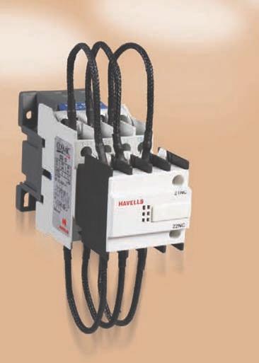
12 Add-on Accessories CN Series : AC (3 Pole / 4 Pole) CD Series : DC (3 Pole / 4 Pole) Contactor (IS / IEC ) Type * CRN1 04 CN1 09 CN1 12 Current Rating at 415V 50Hz AC3 -Ie A Common Add-on Accessories Add-on Side / Front Mounted Aux. Contact Block Rated operational curent at 240V / 415V - 6A / 4A Rated thermal current I th - 10A Rated insulation voltage - 750V Duty - AC 15 Contact Configuration 1NO+1NC 2NO Type CAS11 CAS20 Add-on Pneumatic Timer Block Type (ON Delay / OFF Delay) Time A - (0.1-3s) / B - (0.1-30s) / C - (10-180s) Timer type CPT1A / CPT1B / CPT1C Mechanical interlock Mechanical interlock Type MN1234 Thermal Overload Relay Overload Relay Type RT21 RT11 For Mounting with 3P / 4P Contactor Type : CN1 09 to CN4 32 Current Range in Amp. (Suffix Code No.) Features Protection against overload & single phasing Potential free trip contacts (1NO & 1NC) Ambient temperature compensated (-5ºC to +55 ºC) Auto - Manual reset / Manual reset facility Test mode facility Contactor mounting / Individual mounting with adaptor A H A H B 4-6 J B 4-6 J C K C K D 7-10 L D 7-10 L E 9-13 M E M F N F N G P G P * Side mounted aux. contact not applicable for 3P / 4P contactors with DC coil * Mechanical interlock not applicable for 3P / 4P contactors with DC coil (9A - 95A) 12


13 CN2 18 CN3 25 CN4 32 CN5 40 CN5 50 CN5 65 CN6 80 CN NO+1NC 2NO+2NC 3NO+1NC 4NO CAF11 CAF22 CAF31 CAF40 CPT2A / CPT2B / CPT2C MN56 RT22 RT12 RT23 RT13 CN4 32 to CN5 65 CN5 40 to CN6 95 CN5 40 to CN Q Q T V R R U W V X W Y X Y Z 13


14 Ease of accessibility and maintenance Step 2 Step 1 Step 3 Untighten the screws of top housing block Removal of shroud Removal of top housing block Coil of the contactor Separation of top housing block from contactor base Step 4 Removal of coil Step 6 Step 5 14


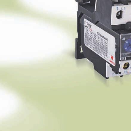
15 CN Series Contactors & Accessories Contactor Side mount aux. Side mount aux. Contactor Mechanical interlock CN109 T10 CN109 T10 Pneumatic timer block ON / OFF delay Front mount aux. Front mount aux. Manual reset thermal relay Auto / manual reset thermal relay 15
16 Standard conformity : IS/ IEC Insulation voltage Ui : 1000 V Operation voltage Ue : 1000 V Ambient Temperature Range : -5 ºC to +55 ºC Operating Altitude : 3000 m Mounting Position : ±30º (Vertical Plane) Contactor Type * CH1 115 CH1 150 CH2 185 Current Rating at 415V 50Hz AC3 -Ie A No. of poles 3P, 4P 3P, 4P 3P, 4P Impulse withstand voltage Uimp kv Making Capacity A Breaking Capacity at 415V A AC1 Duty : Rated Operational Current I th A Max. Power Rating at 415V KW AC2 / AC3 Duty Rated Operational Current I e A Max. Power Rating at 415V For Electrical Life (Refer. electrical life plot) KW/HP 59 / / / 125 AC4 Duty : Rated Operational Current I e A Max. Power Rating at 415V For Electrical Life (Refer. electrical life plot) KW/HP 59 / / / 125 Mechanical Life (Million Ops.) Switching Frequency (No load) Ops. / Hr Impedence Per Pole m.ohm Short Time Current at 40 0 C (1sec.) A Short Circuit Back Up Fuse Rating A Max. Cable Size Sq. mm Tightening Torque Nm Weight Over all Dimension (W x H x D) 3P Kg P Kg P mm 164 x 162 x x 170 x x 174 x 181 4P mm 200 x 162 x x 170 x x 174 x 181 Control Circuit (AC Coil) Operating Voltage Range V Power Consumption (inrush / hold ) 50 Hz VA 550 / / / 55 Power Consumption (inrush / hold ) 60 Hz VA 660 / / / 66 Heat Dissipation 50/60Hz W Coil pickup time Coil drop out time ms * CH Series, AC contactor suitable for both AC & DC coil. 16
17 CH2 225 CH3 265 CH4 330 CH5 400 CH6 500 CH P, 4P 3P, 4P 3P, 4P 3P, 4P 3P, 4P 3P, 4P / / / / / / / / / / / / X150 2X240 2(60X5) Busbar x 197 x x 203 x x 206 x x 206 x x 238 x x 304 x x 197 x x 203 x x 206 x x 206 x x 238 x x 304 x / / / / / / / / / / / /

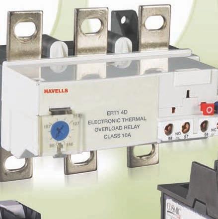
18 Add-on Accessories CH Series - AC / DC : (3 Pole / 4 Pole) Contactor (IS / IEC : ) Type CH1 115 CH1 150 CH2 185 Current Rating at 415V 50Hz AC3 -Ie A Common Add-on Accessories Add-on Front Mounted Aux. Contact Block Rated operational curent at 240V / 415V - 6A / 4A Rated thermal current I th - 10A Rated insulation voltage - 750V Duty - AC 15 Contact Configuration Type 1NO+1NC CAF11 Add-on Pneumatic Timer Block Type (ON Delay / OFF Delay) Time A - (0.1-3s) / B - (0.1-30s) / C - (10-180s) Timer Type CPT1A / CPT1B / CPT1C Mechanical interlock type No. Mechanical interlock type No. MH 1 Electronic Overload Relay Overload Relay Type ERT1 (Individual mounting) For Mounting with 3P / 4P Contactor Type : CH1 115 to CH2 185 Current Range in Amp. (Suffix Code No.) ERT1 4 A Features Electronic Version Protection against overload & single phasing Potential free trip contacts (1NO & 1NC) Ambient temperature compensated ( -5 C to +55 C) Manual reset facility Test mode facility Individual mounting ERT1 4 B ERT1 4 C ERT1 4 D 18
 CH2 185 to CH7 630 132-220 ERT1 5 E 200-330 ERT1 6 F 300-500 ERT1 6 G 380-630 ERT1 6 H 19")
19 CH2 225 CH3 265 CH4 330 CH5 400 CH6 500 CH NO+2NC 3NO+1NC 4NO CAF22 CAF31 CAF40 CPT2A / CPT2B / CPT2C MH 2 MH MH 6 7 ERT1 (Individual mounting) CH2 185 to CH ERT1 5 E ERT1 6 F ERT1 6 G ERT1 6 H 19
20 Ease of accessibility and maintenance 20


21 CH Series Contactors & Accessories Contactor Mechanical interlock Contactor Pneumatic timer block ON / OFF delay Front mount aux. Front mount aux. Manual reset electronic relay 21
22 Contactor Electrical Life CN-Series CH-Series
23 Operational Current & Power Rating CN Frame Contactor Type CN1 09 CN1 12 CN2 18 CN3 25 CN4 32 CN5 40 CN5 50 CN5 65 CN6 80 CN6 95 Max. Operational Current AC-3 9A 12A 18A 25A 32A 40A 50A 65A 80A 95A U e 220/240V kw HP U e 380/400V kw HP U e 415V kw HP U e 440V kw HP U e 500V kw HP U e 660/690V kw HP CH Frame Contactor Type CH1 115 CH1 150 CH2 185 CH2 225 CH3 265 CH4 330 CH5 400 CH6 500 CH7 630 Max. Operational Current AC-3 115A 150A 185A 225A 265A 330A 400A 500A 630A U e 220/240V kw HP U e 380/400V kw HP U e 415V kw HP U e 440V kw HP U e 500V kw HP U e 660/690V kw HP Note : For Ue = 1000 V - operational current and power rating provided on request. 23
24 Standardized Utilization Categories Utilization Category Alternate Current AC-1 Non inductive or slightly inductive loads, resistance furnaces AC-2 Slip-ring motors starting, switching off Standardized Utilization Categories according to IEC Specification Ie Normal Duty Occasional Duty Make Break Ie Make Break l/le u/ue Cosφ l/le u/ue Cosφ l/le u/ue Cosφ l/le u/ue Cosφ All values All values All values All values 4(3) (3) 4(3) (3) AC-3 Squirrel-cage motors: starting, le < 17A le <= 100A Switching off motors during running le > 17A Ie >100A AC-4 Squirrel-cage motors: starting, Ie < 17A Ie <=100A plugging (1), inching (1) Ie > 17A Ie > 100A AC-5a Switching of electric discharge lamp controls AC-5b Switching of incandescent lamps All values All values All values 1 1 (4) 1 1 (4) All values (4) (4) AC-6a Switching of transformers All values under examination All values Ac-6b Switching of capacitor banks All values under examination All values Refer table 7b of IEC Direct Current Ie u/ue L/R(ms) Ie u/ue L/R(ms) Ie u/ue L/R(ms) Ie u/ue L/R(ms) DC-1 Non-inductive or slightly inductive loads, resistance furnaces. DC-3 Shunt-motors : starting, plugging (1) inching(2), dynamic breaking of DC motors DC-5 Series-motors: starting, plugging(1) inching(1), dynamic braking of DC motors DC-6 Switching of incandescent lamps. Control Circuit Devices (IEC ) AC-14 Control of small electromagnetic loads (<=72VA) AC-15 control of electromagnetic loads (> 72 VA) All values All values All values All values All values All values All values 1 1 (4) 1 1 (4) All values (4) (4) I/Ie u/ue Cos φ I/Ie u/ue Cos φ I/Ie u/ue Cos φ I/Ie u/ue Cos φ All values All values All values All values Direct Current I/Ie u/ue To.95 I/Ie u/ue To.95 I/Ie u/ue To.95 I/Ie u/ue To.95 DC-13 Control of electromagnets All values 1 1 6P(5) 1 1 6P(5) All values P(5) P(5) Each utilization category is characterized by the values of the current to be made and switched (expressed as multiples of the rated operational current) and by the relevant voltages, power factor (AC duties) or time constant (DC duties) under normal or occasional conditions. I - Applied current U - applied voltage Cos φ - Power factor Ie - rated operational current Ue - Rated operational voltage L/R - time constant Note: 1. Plugging is understood to be stopping or reversing the motor rapidly by reversing motor primary connections while the motor is running. 2. Inching (jogging) is referred to energizing a motor once or repeated by short periods to obtain small movements of the driven mechanism. 3. Values indicated apply to stator contactors. For rotor contactors, a test will be carried out with a current value equivalent to 4 times the rotor rated current & with Cos φ = Test carried out with a load of incandescent lamps 5. The value 6P(W) is obtained from an empirical formula & represents the significant part of the D.C. magnetic loads upto the top limit of P=50W or 6P=300ms. Loads having an energy consumption over 50W are constituted by parallel lower wattage loads, consequently, 300ms must be considered a top limit whatever is the value of Power consumption. 24
25 Motor Currents Average full-load currents of 3-phase squirrel cage motors, 3-phase 4-pole motors, 50/60 Hz Power 200 / 208 V 220 V 230 V (1) Motor Currents 380 V 400 V 415 V These values are given as a guide. They may vary depending on the type of motor and manufacturer. (1) values conforming to the NEC (National Electrical Code) / 440 V 460 V (1) 500 / 525 V 575 V (1) 660 V 690 V 750 V kw HP A A A A A A A A A A A A A

26 Ordering Information Control Relay with AC Coil Frame size I th Contact arrangement NO NC Type Cat. No 2 2 CRN1-22* IHACR 22* 1 10A 3 1 CRN1-31* IHACR 31* 4 0 CRN1-40* IHACR 40* Control Relay with DC Coil Frame size I th 1 10A Contact arrangement NO NC Type Cat. No 2 2 CRD1-22* IHDCR 22* 3 1 CRD1-31* IHDCR 31* 4 0 CRD1-40* IHDCR 40* Contactor 3-Pole with AC Coil (9A to 95A) Frame Size AC-3 Duty Rating at 415V, 50 Hz AC-1 Duty Rating at 415V, 50 Hz Power Poles I e Amp. Kw. HP I th Amp. NO NC Auxilliary Contact Arrangement Type Cat. No CN1 09 T10* IHPAA009110* CN1 09 T01* IHPAA009101* CN1 12 T10* IHPAA012110* CN1 12 T01* IHPAA012101* CN2 18 T10* IHPAA018210* CN2 18 T01* IHPAA018201* CN3 25 T10* IHPAA025310* CN3 25 T01* IHPAA025301* CN4 32 T10* IHPAA032410* CN4 32 T01* IHPAA032401* CN5 40 T11* IHPAA040511* CN5 50 T11* IHPAA050511* CN5 65 T11* IHPAA065511* CN6 80 T11* IHPAA080611* CN6 95 T11* IHPAA095611* 26


27 Contactor 3-Pole with AC coil (115A to 630A) Frame Size AC-3 Duty Rating at 415V, 50 Hz I e Amp. Kw. HP I th Amp. AC-1 Duty Rating at 415V, 50 Hz Power Poles Type Cat. No CH1 115 T* IHPAA115100* CH1 150 T* IHPAA150100* CH2 185 T* IHPAA185200* CH2 225 T* IHPAA225200* CH3 265 T* IHPAA265300* CH4 330 T* IHPAA330400* CH5 400 T* IHPAA400500* CH6 500 T* IHPAA500600* CH7 630 T* IHPAA630700* *To complete the Cat no. suffix the coil voltage from the coil voltage table Note: 1. For additional aux. contacts front/side mounted and mechanical interlock refer add-on accessories table. 2. Non standard coil voltages are supplied on request. AC Coils Code* A C E G H J K AC Voltage 24V 48V 110V 220V 240V 380V 415V 27
28 Contactor 4-Pole with AC Coil (9A to 95A) Frame Size AC-1 Duty Rating at 415V, 50 Hz AC-3 Duty Rating at 415V, 50 Hz Power Poles I th Amp. I e Amp. Kw. HP Type Cat. No CN1 09 F* IHPAC009100* CN1 12 F* IHPAC012100* CN3 25 F* IHPAC025300* CN5 40 F* IHPAC040500* CN5 50 F* IHPAC050500* CN5 65 F* IHPAC065500* CN6 80 F* IHPAC080600* CN6 95 F* IHPAC095600* Frame Size 1 2 AC-1 Duty Rating at 415V, 50 Hz Contactor 4-Pole with AC coil (115A to 630A) AC-3 Duty Rating at 415V, 50 Hz Power Poles I th Amp. I e Amp. Kw. HP Type Cat. No CH1 115 F* IHPAC115100* CH1 150 F* IHPAC150100* CH2 185 F* IHPAC185200* CH2 225 F* IHPAC225200* CH3 265 F* IHPAC265300* CH4 330 F* IHPAC330400* CH5 400 F* IHPAC400500* CH6 500 F* IHPAC500600* CH7 630 F* IHPAC630700* *To complete the Cat no. suffix the coil voltage from the coil voltage table Note: 1. For additional aux. contacts front/side mounted and mechanical interlock refer add-on accessories table. 2. Non standard coil voltages are supplied on request. 28


29 AC Coils Code* A C E G H J K AC Voltage 24V 48V 110V 220V 240V 380V 415V Contactor 3 Pole with DC Coil (9A to 95A) Frame Size AC-3 Duty Rating at 415V, 50 Hz AC-1 Duty Rating at 415V, 50 Hz Power Poles I e Amp. Kw. HP I th Amp. NO NC Auxilliary Contact Arrangement Type Cat. No CD1 09 T10* IHPAB009110* CD1 09 T01* IHPAB009101* CD1 12 T10* IHPAB012110* CD1 12 T01* IHPAB012101* CD2 18 T10* IHPAB018210* CD2 18 T01* IHPAB018201* CD3 25 T10* IHPAB025310* CD3 25 T01* IHPAB025301* CD4 32 T10* IHPAB032410* CD4 32 T01* IHPAB032401* CD5 40 T11* IHPAB040511* CD5 50 T11* IHPAB050511* CD5 65 T11* IHPAB065511* CD6 80 T11* IHPAB080611* CD6 95 T11* IHPAB095611* 29
30 Frame Size AC-3 Duty Rating at 415V, 50 Hz Contactor 3 Pole with DC coil (115A to 630A) AC-1 Duty Rating at 415V, 50 Hz I e Amp. Kw. HP I th Amp. Power Poles Type Cat. No CH1 115 T* IHPAB115100* CH1 150 T* IHPAB150100* CH2 185 T* IHPAB185200* CH2 225 T* IHPAB225200* CH3 265 T* IHPAB265300* CH4 330 T* IHPAB330400* CH5 400 T* IHPAB400500* CH6 500 T* IHPAB500600* CH7 630 T* IHPAB630700* *To complete the Cat no. suffix the coil voltage from the coil voltage table Note: 1. For additional aux. contacts, front mounted refer add-on accessories table. 2. Non standard coil voltages are supplied on request. DC Coils Code* A C E G DC Voltage 24V 48V 110V 220V 30
31 Contactor 4-Pole with DC Coil (9A to 95A) Frame Size AC-1 Duty Rating at 415V, 50 Hz AC-3 Duty Rating at 415V, 50 Hz Power Poles I th Amp. I e Amp. Kw. HP Type Cat. No CD1 09 F* IHPAD009100* CD1 12 F* IHPAD012100* CD3 25 F* IHPAD025300* CD5 40 F* IHPAD040500* CD5 50 F* IHPAD050500* CD5 65 F* IHPAD065500* CD6 80 F* IHPAD080600* CD6 95 F* IHPAD095600* *To complete the Cat no. suffix the coil voltage from the coil voltage table Note: 1. For additional aux. contacts, front mounted refer add-on accessories table. 2. Non standard coil voltages are supplied on request. DC Coils Code* A C E G DC Voltage 24V 48V 110V 220V 31


32 Frame Size AC-1 Duty Rating at 415V, 50 Hz Contactors 4-Pole with DC coil (115A to 630A) AC-3 Duty Rating at 415V, 50 Hz Power Poles I th Amp. I e Amp. Kw. HP Type Cat. No CH1 115 F* IHPAD115100* CH1 150 F* IHPAD150100* CH2 185 F* IHPAD185200* CH2 225 F* IHPAD225200* CH3 265 F* IHPAD265300* CH4 330 F* IHPAD330400* CH5 400 F* IHPAD400500* CH6 500 F* IHPAD500600* CH7 630 F* IHPAD630700* *To complete the Cat no. suffix the coil voltage from the coil voltage table Note: 1. For additional aux. contacts, front mounted refer add-on accessories table. 2. Non standard coil voltages are supplied on request. DC Coils Code* A C E G DC Voltage 24V 48V 110V 220V 32

33 Add on Accessories: Auxilliary Contact Block Description Suitable for Mounting on Contactors Contact Configuration NO NC Type Cat No. Side Block Front Block CN Frame size 1-6 9A-95A 3P/4P CN/CD Frame size 1-6 9A-95A 3P/4P & CH Frame Size A-630A 3P / 4P 1 1 CAS11 ISPNASM CAS20 ISPNASM CAF11 ISPNAFM CAF22 ISPNAFM CAF31 ISPNAFM CAF40 ISPNAFM740 ON Delay Add on Accessories: Pneumatic Timer Block Suitable for Mounting on Contactors Type Cat No s CPT1A IHNN s CN/CD/CH 9A-630A CPT1B IHNN s CPT1C IHNN6000 OFF Delay Add on Accessories: Pneumatic Timer Block Suitable for Mounting on Contactors Type Cat No s CPT2A IHNF s CN/CD/CH 9A-630A CPT2B IHNF s CPT2C IHNF6000 Mechanical Interlock Site Fitment Type Suitable for Mounting on Contactors Type Cat No. CN1 to CN4 MN ISPNM4SV CN5 to CN6 MN 5 6 ISPNM6SV CH1 MH 1 ISPHM1SV CH2 MH 2 ISPHM2SV CH3, CH4, CH5 MH ISPHM5SV CH6, CH7 MH 6 7 ISPHM7SV 33
34 Spare Coils (AC) For use of Contactor type (3 Pole) Type Cat. No. CRN1, CN1 09, CN1 12, CN2 18 CX1-2* ISPNCN2* CN3 25, CN4 32 CX1-4* ISPNCN4* CN5 40, CN5 50, CN5 65, CN6 80, CN6 95 CX1-6* ISPNCN6* CH1 115, CH1 150 CY1-1* ISPNCH1* CH2 185, CH2 225 CY1-2* ISPNCH2* CH3 265 CY1-3* ISPNCH3* CH4 330 CY1-4* ISPNCH4* CH5 400 CY1-5* ISPNCH5* CH6 500 CY1-6* ISPNCH6* CH7 630 CY1-7* ISPNCH7* *To complete the type/ cat no. suffix the coil voltage from the coil voltage table Spare Coils (AC) For use of Contactor type (4 Pole) Type Cat. No. CRN1, CN1 09, CN1 12 CX1-2* ISPNCN2* CN3 25 CX1-4* ISPNCN4* CN5 40, CN5 50, CN5 65, CN6 80, CN6 95 CX1-6* ISPNCN6* CH1 115, CH1 150 CY1-1* ISPNCH1* CH2 185, CH2 225 CY1-2* ISPNCH2* CH3 265 CY1-3* ISPNCH3* CH4 330 CY1-4* ISPNCH4* CH5 400 CY1-5* ISPNCH5* CH6 500 CY1-6* ISPNCH6* CH7 630 CY1-7* ISPNCH7* *To complete the type/ cat no. suffix the coil voltage from the coil voltage table AC Coils Code* A C E G H J K AC Voltage 24V 48V 110V 220V 240V 380V 415V 34
35 Spare Coils (DC) For use of Contactor type (3 Pole) Type Cat. No. CRD1, CD1 09, CD1 12, CD2 18 CX4-2* ISPNDN2* CD3 25, CD4 32 CX4-4* ISPNDN4* CD5 40, CD5 50, CD5 65, CD6 80, CD6 95 CX4-6* ISPNDN6* CH1 115, CH1 150 CY4-1* ISPNDH1* CH2 185, CH2 225 CY4-2* ISPNDH2* CH3 265, CH4 330 CY4-34* ISPNDH34* CH5 400 CY4-5* ISPNDH5* CH6 500 CY4-6* ISPNDH6* CH7 630 CY4-7* ISPNDH7* *To complete the type/ cat no. suffix the coil voltage from the coil voltage table Spare Coils (DC) For use of Contactor type (4 Pole) Type Cat. No. CRD1, CD1 09, CD1 12 CX4-2* ISPNDN2* CD3 25 CX4-4* ISPNDN4* CD5 40, CD5 50, CD5 65, CD6 80, CD6 95 CX4-6* ISPNDN6* CH1 115, CH1 150 CY4-1* ISPNDH1* CH2 185, CH2 225 CY4-2* ISPNDH2* CH3 265 CY4-3* ISPNDH3* CH4 330 CY4-4* ISPNDH4* CH5 400 CY4-5* ISPNDH5* CH6 500 CY4-6* ISPNDH6* CH7 630 CY4-7* ISPNDH7* *To complete the type/ cat no. suffix the coil voltage from the coil voltage table DC Coils Code* A C E G DC Voltage 24V 48V 110V 220V 35
36 Dimension (in mm) CN series AC contactor with AC coil - 3 Pole / 4 Pole CN CN4 32 CN CN6 95 D/E C A φ D/E φ B b B b a C a A Dimension Detail Type No A B C D E a b F CN P /35 50/ P /35 50/ CN2 18 3P /35 50/ CN3 25 3P P CN4 32 3P CN P / P / CN P / P / D: With front add on block E: With pneumatic timer block Note: Dimension of CRN1 same as CN
37 Dimension (in mm) CD series DC contactor with DC coil - 3 Pole / 4 Pole CD1 9 - CD4 32 CD CD6 95 D 4 Φ D 6 Φ B 50/60 B 100/ C a A G 53 C a a E E 12.5 A G Dimension, in mm Type No A B C D E a F G CD P P CD2 18 3P CD3 25 3P P CD4 32 3P CD P P CD P P D: With front add on block E: With pneumatic timer block G: Interlocking mechanism Note: Dimension of CRD1 same as CD
38 Dimension (in mm) CH series AC contactor with AC / DC coil - 3 Pole / 4 Pole CH CH4 330 II S S1 CH115 - M6 X 25 CH150 - M8 X 25 CH185 - M8 X 25 CH225 - M10 X 35 CH265 - M10 X 35 CH330 - M10 X 35 4 x φ 6.5 X1 X1 b b2 M b1 J J1 II G1 c L Q P P Q1 a f Z G Y Dimension, in mm Type No a b b1 b2 c f G G1 J J1 L M P Q Q1 S S1 Y Z CH1 115 CH1 150 CH2 185 CH2 225 CH3 265 CH P P P P P P P P P P P P f : Minimum distance required for coil removal 38
39 CH CH S x M10 x 35 8X φ 8.5 Dimension, in mm Type No a b b2 c f G* Gmin Gmax G1 G1min G1max J L M P Q Q1 S CH5 400 CH P P P P x M12 x X1 X1 209 b b2 M X1 II 23.5 G G1 J L Q P P Q1 c a f CH7 630 X1 4 x ø G J Q Q1 a 181* Dimension, in mm Type No a G Gmin Gmax J1 Q Q1 CH P CH P * Minimum distance required for coil removal 39


40 THERMAL OVERLOAD RELAY


41


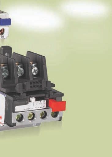
42 Contactors Contactors and and Overload Relays Introduction A wide range of bimetal thermal overload relays are offered for close protection of motors & other inductive loads against overload, single phasing & unbalanced system voltages. Thermal Overload Relays are ambient temperature compensated and are independent of variation in ambient temperature. Protection against single phasing & unbalanced voltages has been provided by means of differential tripping mechanism which ensures positive protection of motors / loads. They are provided with 1NO + 1NC potentially free contacts which can be used for signalling. The relay can be used in either Auto or Manual reset mode. Standards : IS / IEC : Type : Auto / manual reset Manual reset Range : Contactor Mounting - 0.1A - 93A in 24 direct reading version (Auto / manual). Contactor Mounting - 0.1A - 80A in 20 direct reading version (Manual). Individual Mounting - 0.1A - 93A in 24 direct reading version (Auto / manual & Manual). Electronic Individual Mounting - 30A - 630A in 8 direct reading version (Manual). Features : Protection against overload & single phasing Auto manual / manual reset facility Ambient temperature compensated Potential free trip contacts Test mode facility Contactor mounting / Individual mounting with adaptor Matching to contactor rating upto 95A Principle of Operation The heating elements in the main circuit heat the bimetal tripping elements corresponding to the motor load current. The heating elements are calibrated such that the set trip point is achieved in accordance with the standards. By means of trip bar, the movement / deflection of the bimetal is transmitted to plunger which in turn operates the trip mechanism and thus the contacts are separated. The trip point can be easily set on a scale in accordance with the nominal motor rated current. Bimetal elements for compensating the trip point in case of different ambient temperature is fitted on the trip lever. Buttons are used for testing the circuit to be protected, for resetting by hand and for conversion from manual to auto reset mode. Differential Mechanism The relay operates on the differential system of protection provided by the double slide mechanism. Under single phasing and unbalanced voltage conditions, the two slides of the relay undergo differential deflection. One slide senses the movement of the bimetal that deflects the maximum, while the other senses the minimum deflection. The slides are linked in such a way that the difference in movements of the two slides is amplified for actuation of the trip lever. This leads to accelerated tripping under single phasing. 42


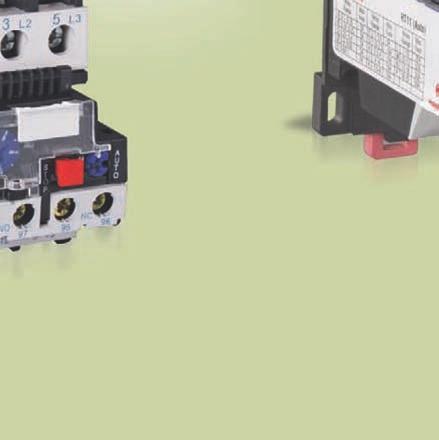
43 Contactors and and Overload Relays Relays Thermal Overload Relay Parts Identification Adjustable prongs (for mounting on contactor) Dial cover Range setting dial Test button Potential free contacts OFF button Auto / manual mode knob Potential free contacts Motor terminal Electronic Overload Relay The ERT1 4 overload relays are specifically made suitable for operating conditions of motors. They provide protection against Thermal overload of three phase or single phase balanced or unbalanced circuits Phase failure and large phase unbalance Protracted starting times Prolonged stalled rotor condition These electronic overload relays are ambient temperature compensated and based on differential principle & provided with adjustable current setting dial, trip indicator, manual reset & test facility. The current setting can be locked by sealing the transparent protective dial cover. Parts Identification Terminal Marking Reset E NC NO Trip indicator Test button Range setting dial OFF button Manual reset E Test NC NO Dial cover Potential free contacts 43
44 Technical Information Conformity of Standard : IS / IEC Ambient temperature range : -5 C C Operating Altitude : 2000 meters Pollution degree : 3 Degree of protection : IP 20 Trip Class : 10A Thermal Overload Relay Over Load Relay Thermal Type Type of Reset Auto / Manual Manual Current Range Contactor Mounting A Individual Mounting (with adaptor) A Rated Insulation Voltage ( Ui ) V Rated Operational Voltage ( Ue ) V Switching Frequency OPS. / Hr Terminal Capacity Contactor Mounting (RT 21) / (RT 11) Sq. mm Contactor Mounting (RT 22) / (RT 12) Sq. mm Contactor Mounting (RT 23) / (RT 13) Sq. mm Auxilliary Circuit Insulation Voltage V Rated Thermal Current A 6 6 Rated Current (AC-15) at 220V AC A at 415 V AC A (DC-13) at 220 V DC A Auxilliay Terminal Sq. mm 2 x x 2.5 Weight / Dimension O / L relay auto / manual reset O / L relay manual reset Type kg W x H x D Type kg W x H x D RT x 66 x 94 RT x 56 x 91 RT x 78 x 94 RT x 73 x 118 RT x 83 x 114 RT x 73 x
 V 1000 Rated Operational Voltage ( Ue ) V 415")
45 Technical Information Conformity of Standard : IS / IEC Ambient temperature range : -5 0 C C Operating Altitude : 2000 meters Pollution degree : 3 Degree of protection : IP 20 Trip Class : 10A Electronic Overload Relay 45 Over Load Relay Electronic Type Type of Reset Manual Current Range A Rated Insulation Voltage ( Ui ) V 1000 Rated Operational Voltage ( Ue ) V 415 Rated Frequency Hz 50 / 60 Power Terminal Connection Width of Terminal lug mm 20 Clamping Screw M8 Tightening torque Nm 18 Trip Indication On relay front Test Function On relay front Stop Function Through stop push button Tripping limit No Trip 1.05 In Trip 1.2 In Sensitivity to Single Phasing Yes Current Adjustment Setting dial on relay front Security Sealing Yes Weight / Dimension Manual reset Type kg W x H x D ERT1 4A x 96 x ERT1 4B x 96 x ERT1 4C x 96 x ERT1 4D x 96 x ERT1 5E x 101 x ERT1 6F x x ERT1 6G x x ERT1 6H x x


46 Time / Current Characteristics Average operating time related to multiples of the tripping current Thermal overload relay Time in Seconds Time in Seconds Current multiples Electronic overload relay Cold state Hot state Current multiples
47 Relay Selection Chart DOL Starting 3φ Motor Rating at 415V 50Hz. Approx. Full Load Current Relay Range Backup Fuse Rating KW HP Amp. Amp. Amp / / Star Delta Starting 3φ Motor Rating at 415V 50Hz. Full Load Line current Full Load phase Current Relay Range Backup Fuse Rating KW HP Amp Amp Amp Amp


48 Ordering Information Thermal Over Load Relay (Auto / Manual Reset) Relay Frame size Relay Range Suitable for Contactor Frame size Type Cat. No. Individual Mounting Block RT21A IHNR 11AA RT21B IHNR 11AB RT21C IHNR 11AC RT21D IHNR 11AD RT21E IHNR 11AE RT21F IHNR 11AF RT21G IHNR 11AG CN1to CN RT21H IHNR 11AH 4-6 RT21J IHNR 11AJ Type RTA2-25 Cat No. ISSTRX RT21K IHNR11AK 7-10 RT21L IHNR 11AL 9-13 RT21M IHNR 11AM RT21N IHNR 11AN RT21P IHNR 11AP RT22Q IHNR22AQ Type RTA2-36 Cat CN4 to CN5 No RT22R IHNR22AR ISSTRX RT23T IHNR33AT RT23U IHNR33AU RT23V IHNR33AV CN5 to CN6 RT23W IHNR33AW RT23X IHNR33AX RT23Y IHNR33AY RT23Z IHNR33AZ Type RTA2-93 Cat No. ISSTRX


49 "Relay Frame size" 1 2 Relay Range Thermal Over Load Relay (Manual Reset) Suitable for Contactor Frame size Type RT11A Cat. No IHNR11MA RT11B IHNR11MB RT11C IHNR11MC RT11D IHNR11MD RT11E IHNR11ME RT11F IHNR11MF RT11G IHNR11MG CN 1 to CN RT11H IHNR11MH 4-6 RT11J IHNR11MJ RT11K IHNR11MK 7-10 RT11L IHNR11ML RT11M IHNR11MM RT11N IHNR11MN RT11P IHNR11MP RT12Q IHNR22MQ CN 5 to CN RT12R IHNR22MR Individual Mounting Block Type RTA1-25 Cat No. ISSTRX RT13V IHNR33MV RT13W IHNR33MW CN 5 to CN RT13X IHNR33MX RT13Y IHNR33MY Type RTA1-80 Cat No. ISSTRX Relay Frame size 4 Relay Range Electronic Overload Relay (Manual Reset) Suitable for Contactor Frame size Type ERT1 4A Cat. No IHETR ERT1 4B IHETR080 CH 1 to CH ERT1 4C IHETR ERT1 4D IHETR CH 2 to CH 5 ERT1 5E IHETR ERT1 6F IHETR CH 2 to CH 7 ERT1 6G IHETR ERT1 6H IHETR630 49
50 Dimension (in mm) Thermal Overload Relay (Auto / Manual reset) RT max max 94max 46max Without adapter block R max With adapter block RT max 94max 90max max Without adapter block max 55max With adapter block 50
51 RT max 6 117max 72max Without adapter block 125max max max With adapter block Thermal Overload Relay (Manual Reset) RT R2.4 56max ± max 91max Without adapter block 50 R max ± max 93max With adapter block 51
52 RT max max 63.5max Without adapter block max 39 78max 76max With adapter block RT max max 63.5max Without adapter block max 39 78max 76max With adapter block 52
53 Electronic Overload Relay (Manual reset) ERT1 4D a xØ a 6.5 x ERT1 4A 8.5 x ERT1 4B, ERT1 4C, & ERT1 4D ERT1 5E Ø xØ5.5 ERT1 6H b 30 b Ø11 4xØ b 48 - ERT1 6F 55 - ERT1 6G, ERT1 6H


54 CAPACITOR DUTY CONTACTOR


55 I
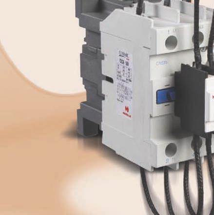
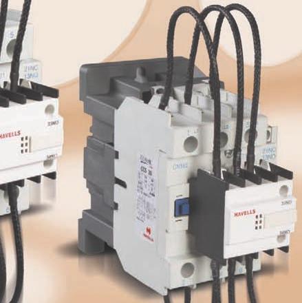
56 Introduction Normal contactor when used for capacitor switching is unable to meet the operational requirements. In fact, at the time of switching, a capacitor effectively appears as a short circuit. The magnitude of capacitor in-rush or charging current will depend upon value of AC voltage level alongwith impedence of feeder cables and supply transformers. When switching individual capacitor bank the charging current peaks upto 30 times the rated capacitor current can occur and incase of multi stage capacitors the in-rush current peaks of more than 180 times the rated capacitor current can occur. Current Current <30 In >180 In In t In t I Single-step capacitor bank Multi-step capacitor banks These large current can flow through contactor since initial in-rush current is taken from both main supply and capacitor already connected. Such in-rush current of high magnitude is undesirable & can weld the main contacts of normal contactors. It is therefore, essential to: (a) Limit the current peak by inserting quick discharge series damping resistance. (b) Use specific Capacitor Duty Contactors. Hence, special Capacitor Duty Contactors are designed to meet Capacitor switching application. Principle of Operation Contactor is fitted with block of three early make auxilliary contacts in series with quick discharge damping six - resistors - 2 per phase to limit peak current to value within contactor making capacity such that normal rated capacitor current is carried by main contacts which, after closing effectively short out the resistors. Standards IS / IEC : Range 12KVAr - 50KVAr in 5 frames Execution 3 Pole Features : High electrical life Low watt loss & conservation of energy Cost saving & less maintenance Safety against high voltage 56
57 Technical Information Standard conformity : IS / IEC : Utilisation category : AC-6b Ambient temperature range : 5 C C Contactor for capacitor switching Contactor Type CC2-12 CC3-18 CC4-20 CC5-30 CC6-50 Rated Current at 415V 50Hz, AC3 - ( le ) A No. of Poles Rated Insulation Voltage ( Ui ) V Rated Operational Voltage ( Ue ) V Maximum Switching Capacity ( 40 C ) Mechanical Life No. of Ops. (Million) Electrical Life at Rated Load No. of Ops. (Million) at 220V/240V KVAr at 415V/440V Maximum operating rate Ops./Hr Terminal Capacity No. of Cables Flexible / Solid Max. Cable Size Sq. mm 2.5 / 4 4 / 6 4 / 10 6 /16 16 / 25 Weight Kg Overall Dimension (W x H x D) mm 56x140x130 58x140x136 58x140x137 75x180x150 85x200x160 Control Circuit (AC coil) Operating Voltage Range (50/ 60 Hz) V Power Consumption 50Hz - Inrush VA Sealed VA Hz - Inrush VA Sealed VA Heat dissipation (50/ 60 Hz) W Coil pick up time ms Coil drop out time ms Auxilliary Contact Rated Thermal Current A Rated Insulation Voltage V Terminal Capacity No. of Cables Max. Size Sq. mm

58 Ordering Information KVAR Rating at 50/60Hz q 55 0 C Capacitor Duty Contactor 3-Pole with AC Coil Inst. Aux. Contact 220/240V 415/440V NO NC Type Cat. No CC2 1210* IHPAE012210* CC3 1810* IHPAE018310* CC4 2010* IHPAE020410* CC5 3011* IHPAE030511* CC6 5011* IHPAE050611* * To Complete Cat. No. Suffix Voltage Code From Coil Voltage Table Note : 1. For additional aux. contacts block (side mounted type) can be mounted if required. Refer accessories table. For use of Capacitor Duty Contactor type Spare Coils (AC) Type Cat. No. CC2 12 CX1-2* ISPNCN2* CC3 18 & CC4 20 CX1-4* ISPNCN4* CC5 30 & CC6 40 CX1-6* ISPNCN6* *To complete the type/ cat no. suffix the coil voltage from the coil voltage table AC Coils Code* A C E G H J K AC Voltage 24V 48V 110V 220V 240V 380V 415V Dimension (in mm) C B a 1- b A D Type External dimension Dimension, in mm 58 Mounting dimension A B C D a b Ø Din Rail CC / 60 CC / 60 CC / 60 CC / 110 CC / mm mm or 75mm
59 REGIONAL BRANCH OFFICES NORTH - REGIONAL OFFICE : Delhi : QRG Towers, 2D, Sector-126, Expressway, Noida Noida : Tel: , Fax: Chandigarh : Tel: , Fax: , Dehradun : Tel: , Haryana : Tel: / 853, Fax: Noida : Tel: / , Fax: Ludhiana : Tel: / 6024, Fax: Jammu : Tel: , Fax: Jaipur : Tel: , Fax: Lucknow : Tel: , Kanpur : Tel: Airtel: /52/53, /129/130, Fax: EAST - REGIONAL OFFICE : Kolkata : ICC Tower, 5th Floor, 4 India Exchange Place, Kolkata Kolkata : Tel: /52, Fax: Bhubaneshwar : Tel: , , , Fax: Guwahati : Tel: , , Fax: Siliguri : Tel: (RIM) Jamshedpur : Tel: , Patna : Tel: , , Telefax: WEST - REGIONAL OFFICE : Mumbai : 302, Boston House, 3rd Floor Suren Road, CTS No. 260/261, Andheri (E), Mumbai Mumbai : Tel: Ahmedabad : Tel: , , Fax: Indore : Tel: , (Airtel), Fax: Rajkot : Tel: / Nagpur : Tel: , , Pune : Tel: /14 Raipur : Tel: / 01, Telefax: Surat : Telefax: SOUTH - REGIONAL OFFICE : Chennai : Block 1, A & D Wing, Shakthi Towers, 7th Floor, 766, Annna Salai, Chennai Chennai : Tel: , Fax: Bangalore : Tel: , / 2 / 3 /4, Fax: Coimbatore : Telefax: , , Hyderabad : Tel: , , , /0408/6401/6402, Fax: Kochi : Tel: , , , Fax: Vishakapatnam : Tel: , Fax: REPRESENTATIVE OFFICES Goa Solapur Gwalior Jabalpur Hubli Davanagere Gulbarga Mysore Trichy Kathmandu Sambalpur Jalandhar Bhopal Calicut Madurai Trivandrum


60 ACB MCCB Digital MCCB MCCB Panel Board Euroload Change Over Switch Submersible & Motor Starter Switch Disconnector Fuse Load Changeover Switch Camlock fuse holder HRC Fuse Motor Low Voltage Capacitor Although every effort has been made to ensure accuracy in the compilation of the technical detail within this publication. Specifications and performance data are constantly changing. Current details should therefore be checked with Havells Group. ZHIMC00007/FEB2011/APR2011 Havells India Ltd. Corp Office: QRG Towers, 2D, Sector-126, Expressway, Noida (U.P), Ph , Consumer Care No.: (Tollfree), (Landline) (All Connections) Join us on Facebook at and share your ways to save the planet!
Industrial Circuit Protection
 Industrial Circuit Protection Catalogue 2011 Content Contactor... 2-31 Thermal Overload Relay... 32-45 Capacitor Duty Contactor... 46-51 Motor Protection Circuit Breaker... 52-59 Titania Air Circuit
Contactor TECHNICAL INFORMATION - FRAME 1
 TECHNICL INFORMTION - FRME 1 CONTCTOR Type No. Nominal Current Rating at 415v 50Hz C3 - Ie Contact Configuration* Rated Insulation oltage Ui Maximum Operational oltage Overall Dimensions (WxHxD) mbient
Technical Information
 C5 C5- C5- C5- C5- C5-550 ➊ 700 860 1000 1200 Rated Insulation Voltage U i to IEC 947-1 [V] 1000V 1000V 1000V 690V 690V UL/CS [V] 600V Rated Impulse Voltage U imp C5-550 / 700 / 860 [kv] 3.5 C5-1000 /
Approved Standards. Motor Contactor. Main contactor. Accessoires. 21 Motor Contactor J7KN
 Motor Contactor Main contactor AC & DC operated Integrated auxiliary contacts Screw fixing and snap fitting (35 mm DIN rail) up to 45 kw Range from 4 to 110 kw (AC 3, 380/415V) Finger proof ( VBG 4) Accessoires
Ktec Contactors and thermal overloads
 Contactors and thermal overloads Techna KTEC series contactors provide a complete solution for your ac contactor requirements.the range carries TUV, UL & CSA certification, for use in Europe, North America
Essential equipment for all your requirements
 NEW CTX CONTACTORS Essential equipment for all your requirements 9 A TO 310 A THREE-POLE INDUSTRIAL CONTACTORS CTX three-pole industrial contactors, a sense of family The new range of CTX contactors provides
AF09... AF30 3-pole Contactors up to 25 HP / 600 VAC
 AF09... AF0 -pole Contactors up to 25 HP / 600 VAC Contactors and Overload Relays Overview.../0 AF09... AF0 -pole Contactors.../2 Main Technical Data.../8 Main Accessory Fitting Details.../2 Main Accessory.../24
Latch for Contactors 4-pole see page 36. Ratings Rated Aux. Contacts Type Coil voltage 2) AC2 Current Built-in Additional 24 24V= DC 5
 AC2 Current Built-in Additional 24 24V= DC 5") 3-pole DC Operated Ratings Rated Aux. Contacts Type Coil voltage 1) AC2 Current Built-in Additional 24 24V= DC 5 AC3 see 48 60V= DC 6 380V AC1 page 34 110 110V= DC 7 400V 660V 220 220V= DC 8 415V 690V
3-pole DC Operated Ratings Rated Aux. Contacts Type Coil voltage 1) AC2 Current Built-in Additional 24 24V= DC 5 AC3 see 48 60V= DC 6 380V AC1 page 34 110 110V= DC 7 400V 660V 220 220V= DC 8 415V 690V
AF series contactors (9 2650)
") R E32527 R E39322 contactors General purpose and motor applications AF series contactors (9 2650) 3- & 4-pole contactors General purpose up to 2700 A Motor applications up to 50 hp, 900 kw NEMA Sizes 00
R E32527 R E39322 contactors General purpose and motor applications AF series contactors (9 2650) 3- & 4-pole contactors General purpose up to 2700 A Motor applications up to 50 hp, 900 kw NEMA Sizes 00
Controls. CONTACTORS CWB Line (up to 40A)
") Controls CONTACTORS CWB Line (up to 40A) 0800 367 934 Contactors CWB Line (up to 40A) CONTACTORS CWB Line (up to 40A) Summary New WEG CWB Contactors 4 The Technology Within 6 Energy Savings 7 Easy Panel
Controls CONTACTORS CWB Line (up to 40A) 0800 367 934 Contactors CWB Line (up to 40A) CONTACTORS CWB Line (up to 40A) Summary New WEG CWB Contactors 4 The Technology Within 6 Energy Savings 7 Easy Panel
AF09... AF30 3-pole Contactors up to 20 HP / 480 VAC
 AF0... AF0 -pole Contactors up to 20 HP / 480 VAC Contactors and Overload Relays Overview...2 AF0... AF0 -pole Contactors Ordering Details...4 Main Technical Data...20 DC Circuit switching...2 Main Accessory
AF series contactors (9 2650)
") R E32527 R E39322 contactors General purpose and motor applications AF series contactors (9 2650) 3- & 4-pole contactors General purpose up to 2700 A Motor applications up to 50 hp, 900 kw NEMA Sizes 00
R E32527 R E39322 contactors General purpose and motor applications AF series contactors (9 2650) 3- & 4-pole contactors General purpose up to 2700 A Motor applications up to 50 hp, 900 kw NEMA Sizes 00
Model Number Legend. Motor Contactor J7KN. Motor Contactor J7KN 1
 Motor Contactor J7KN Range from 4 to 500 kw (AC 3, 380/415 V) AC and DC operated Integrated auxiliary contacts; integrated aux. contact of J7KN contactors up to 11kW suitable for electronic circuits Screw
TeSys contactors. Use in category DC-1 (resistive loads; time constant L/R y 1 ms) Rated operational current Ie. to be wired in series
 Rated operational current Ie. to be wired in series") Selection 3-pole shockproof contactors FG d.c. supply Selection guide for utilisation categories DC-1 to DC-5 Use in category DC-1 (resistive loads; time constant L/R y 1 ms) Rated operational current
Selection 3-pole shockproof contactors FG d.c. supply Selection guide for utilisation categories DC-1 to DC-5 Use in category DC-1 (resistive loads; time constant L/R y 1 ms) Rated operational current
C -5 to +55 (0.8 to 1.1Uc) Permissible o
 Permissible o") T - Line Contactors 3 & 4 Pole Contactors with C operating coils General Characteristics Type Unit TC1-D09 ~ TC1-D95 Rated insulation voltage (Ui) (Conforming to IEC 158-1) V 750 VDEO 110grC/IEC 60947-4
T - Line Contactors 3 & 4 Pole Contactors with C operating coils General Characteristics Type Unit TC1-D09 ~ TC1-D95 Rated insulation voltage (Ui) (Conforming to IEC 158-1) V 750 VDEO 110grC/IEC 60947-4
Industrial Contactors CTX 3 3P 185A - 800A
 87045 LIMOGES Cedex Telephone: +33 5 55 06 87 87 FAX: +33 5 55 06 88 88 Industrial Contactors CONTENTS PAGES 1. Description - Use... 1 2. Range... 1 3. Overall dimensions... 1 4. Installation - Connection...
A Contactors. Technical Information. CA4 Miniature Contactors. Technical Information A94 CA4. Switching Motor Loads.
 C4 Miniature Contactors Contactors C4 Rated Insulation Voltage U i to IEC 947-1 [V] 500V UL/CS [V] 600V Rated Impulse Voltage U imp [kv] 8 Rated Voltage U e Main Contacts C 50/60Hz [V] 230, 240, 400, 415,
The contactor for large horsepower applications
 Series The complete contactor for heavy industrial applications from 500HP to 900HP R Series contactors provide large horsepower performance with a design that is up to 40% smaller than traditional contactors
AF40... AF96 3-pole contactors Technical data
 Main pole - Utilization characteristics according to IEC Standards IEC 60947- / 60947-4- and EN 60947- / 60947-4- Rated operational voltage Ue max. 690 V Rated frequency (without derating) 50 / 60 Hz Conventional
Meta Solution. Contactors and Overload relays
 Meta Solution Contactors and Overload relays Meta Solution New generation of Contactors from LSIS Contactors and Overload Relays Metasol Contactors Designed to show superior technology: The Metasol series
Meta Solution. Contactors and Overload relays
 Meta Solution Contactors and Overload relays New generation of Contactors from LS Industrial Systems Contactors and Overload Relays Metasol Contactors Designed to show superior technology: The Metasol
Short form catalogue. Motor protection & control
 Short form catalogue Star Series Motor protection & control Motor Protection and Control up to 25 HP / 600 VAC Overview...2 Contactors and Overload Relays...11 4-pole Contactors...41 Control Relays...59
AF09... AF38 4-pole Contactors AC / DC Operated - with Screw Terminals
 AF09... AF38 4-pole Contactors AC / DC Operated - with Screw Terminals 25 to 55 A culus CE Application AF09... AF38 4-pole contactors are used for controlling power circuits up to 600 V AC and 240 V DC.
Essential Loads also use stand by generator systems mostly in process industries as they relate to high restarting times or high down times.
 The need for continuous power supply and its reliability has increased rapidly over the years, especially in all those areas where uninterrupted power supply is a must. Modern systems are power dependent.
Series CA5 Contactors
 Series C5 Contactors The contactor for heavy industrial applications from 500HP to 900HP DISCONTINUED This series is being replaced by the C9 Series of contactors C5 Series contactors provide large horsepower
About us. Switchgear Factory, Mumbai
 About us Larsen & Toubro is a technologydriven USD 8.5 billion company that infuses engineering with imagination. The Company offers a wide range of advanced solutions in the field of Engineering, Construction,
LR9 F OVERLOAD RELAYS
 Issued November 2009 DATA SHEET LR9 F OVERLOAD RELAYS Based on Schneider MKTED2050EN Catalogue General 6 Motor protection Operating conditions There are many possible causes of electric motor failure.
CI-TI Contactors and motor starters Types CI 61 - CI 98
 Data sheet CI-TI Contactors and motor starters s CI 6 - CI 98 Contactors CI 6, CI 7, CI 86 and CI 98 switch powers of up to 0 kw, 7 kw, 45 kw and 55 kw respectively under 80 V - loads. Accessories include
AF40... AF96 3-pole contactors 30 to 60 hp at 480 V AC AC / DC operated with 1 N.O. + 1 N.C. auxiliary contacts
 AF4... AF96 -pole contactors to 6 hp at 48 V AC AC / DC operated with N.O. N.C. auxiliary contacts Description AF4... AF96 contactors are mainly used for controlling -phase motors and power circuits up
3 - Protection components Motor circuit-breakers
 Contents 0 - Protection components Motor circuit-breakers protection components for the motor protection Thermal-magnetic motor circuit-breakers Selection guide..............................................page
 15 16 MCCBs for Power Distribution Technical Specification Frame 100A 250A 250A 400A 400A 630A 800 / 1000 / 1250 Type C DN0-100 D DN1-250 N DN2-250 D N S H DN3B-400 DN3-400 D N D N S V DN3-630 DN4-1250
SICOP. Bimetal Overload Relays Type 3UA5/6 & 3UC5/6. Introduction. Application
 s SICOP Bimetal Overload Relays Type 3UA5/6 & 3UC5/6 Introduction The bimetal overload relays type 3UA5/6 & 3UC5/6 relays are indigenously manufactured and bring to the users a whole range of benefits,
Star Series Motor protection & control
 Contact us ABB Inc. Low Voltage Control Products 16250 W. Glendale Drive New Berlin, WI 53151 Phone: 888-385-1221 Fax: 800-726-41 USA Technical support & Customer Service: 888-385-1221, Option 4 7:30AM
Contactor Catalogue. According to CE, IEC 947, EN Pole & 4 Pole Contactors 4kW - 160kW Thermal Overload
 According to CE, IEC 947, EN 60947 Contactor Catalogue 3 Pole & 4 Pole Contactors 4kW - 160kW Thermal Overload Mini-Contactors 4kW - 5.5kW DC Contactors Mini-Relays 10A Motor Starter DOL, Star-Delta Capacitor
Other Devices. Installation Contactors Z-SCH. Connection diagrams Z-SCH NO 3 NO / 1 NC. Permitted Installation Positions
 Installation Contactors Z-SCH These switching devices have been designed and rated particularly for modular installation in modular distribution boxes for electrical installation or cabinets with device
ASL09..S 3-pole Contactors - Spring Terminals
 4 kw 5 hp ASL09..S 3-pole Contactors - Spring DC Operated Description - 3-pole contactors with spring terminals, - N.C. or N.O. built-in auxiliary contact, - Low coil consumption, - Polarity on the coil
CI-TI Contactors and Motor Starters Type CI 6-50
 Data sheet CI-TI Contactors and Motor Starters CI 6-50 CI-TI contactors and motor starters provide trouble-free switching and maximum protection for costly motors and other electrical equipment. The components
AF / AF12Z pole Contactors AC / DC Operated - with Screw Terminals
 Technical Datasheet 1SBC101404D0201 24/03/11-30-10-.. / Z-30-10-.. 3-pole Contactors AC / DC Operated - with Screw Terminals (Z) contactors are used for controlling power circuits up to 690 V AC and 220
Micro Contactor MA Series
 Relay-sized contactor, making it the world s smallest >3mm contact clearance acc. to IEC 60335-1 for Safety Applications Reversing contactor with mechanical interlock 3 Pole and 1 Aux. Contact NO or NC
Motor Protection Circuit Breakers 3VU13 and 3VU16
 Motor Protection Circuit Breakers 3VU13 and 3VU16 3VU13/3VU16 is suitable for use in fuseless motor feeders upto 11KW/22KW (25A/63A) respectively. 3VU motor protection circuit breakers are used for protection
Motor Protection Circuit Breaker
 Motor Protection Circuit Breaker Catalogue 2011 CONTENT Introduction...4 Features...4 Parts Identification...5 Technical information (MPCB)...5 Technical information (Aux. contact, Fault signalling contact)...6
3VU13, 3VU16 Circuit-Breakers
 3VU3, 3VU6 Circuit-Breakers Description The 3VU3, 3VU6 circuit-breakers are compact circuit-breakers for currents up to 80 A which operate according to the current limiting principle. The devices are used
Technical Information
 Contactors Contactors 95(-EI) 110(-EI) 140(-EI) 180(-EI) 210-EI 250-EI 300-EI 420-EI 630-EI 860-EI Rated Insulation Voltage U i IEC, S, BS, SEV, VDE 0660 [V] 1000V UL; CS [V] 600V Rated Impulse Voltage
The need for continuous power supply and its reliability has increased rapidly over the years, especially in all those areas where uninterrupted
 110 The need for continuous power supply and its reliability has increased rapidly over the years, especially in all those areas where uninterrupted power supply is a must. Modern systems are power dependent.
Selection Guide Motor Control Device Solutions
 Selection Guide Motor Control Device Solutions Expect more and get it from c3controls. Our portfolio of Motor Control Devices consists of worldclass products designed and manufactured to meet your requirements
Manual Motor Starters. Meta-MEC
 Manual Motor Starters Meta-MEC Manual Motor Starters LS Meta-MEC Manual Motor Starters provide completed ranges up to 100A 45 mm 55 mm 32AF 2 2 45 mm 70 mm 63AF 100AF 3 3 Manual LS Meta-MEC Motor Starters
TC Series Contactors Contactors A (AC1) 83 Overload Relays 84 DOL Starters 84 Accessories 85
 83 Overload Relays 84 DOL Starters 84 Accessories 85") 2 - Contactors & Overloads CONTACTORS & OVERLOADS 2 Contactor Selection 82 TC Contactors TC Series Contactors Contactors 20-110A (AC1) 83 Overload Relays 84 DOL Starters 84 Accessories 85 Minicontactors
2 - Contactors & Overloads CONTACTORS & OVERLOADS 2 Contactor Selection 82 TC Contactors TC Series Contactors Contactors 20-110A (AC1) 83 Overload Relays 84 DOL Starters 84 Accessories 85 Minicontactors
Motors Automation Energy Transmission & Distribution Coatings. Automation Contactors - CWM Line
 Motors Automation Energy Transmission & Distribution Coatings Automation Contactors - CWM Line 2 Contactores Compactos CWC0 Contactors - CWM Line Sumary Presentation Accessories Overview 5 Three-Pole Contactors
RSC09 RSC16 RSC22 RSC38 RSC43 RSC63 RSC-AUX
 IEC-Contactor RSC 1 Features Rated operational current 9 63 (C-3) Coil voltages C 24, 230V 3 main contacts and auxiliary contact Extendable with auxiliary contact block Mounting position any 2 Description
Low Voltage Industrial Controls. CWB and RW27-2D. IEC Contactors and Thermal Overload Relays
 CWB and RW27-2D IEC Contactors and Thermal Overload Contactors Overload A-2-800-ASK4WEG www.weg.net/us Contactors CWB CWB Features A-4 Catalog Number Format A-7 Accessories Overview A-8 Part Number List
Contact us. ABB France Electrification Products Division Low Voltage Products and Systems 3, rue Jean Perrin F Chassieu cedex / France
 Contact us ABB France Electrification Products Division Low Voltage Products and Systems 3, rue Jean Perrin F-69687 Chassieu cedex / France You can find the address of your local sales organisation on
FMotor Circuit Controllers
 Technical Information Motor Circuit Controller IEC Performance Data Catalog Number KTA7-25S...32S 0.16A 0.25A 0.4A 0.63A 1A 1.6A 2.5A 4A 6.3A 10A 16A 20A 25A 29A 32A Rated Operational Current, I e [A]
 6300A 15 Optibreak B1 & B2 Optibreak B1 & B2 50/60 Hz Ue Icu [v] [ka] 415 65 690 40 4h 4i 1. Open / close Indication 2. Charge and Discharge Indicator 3. Release the reset button 4. Laser Nameplate
MAKING MODERN LIVING POSSIBLE. Technical brochure. Minicontactors CI 5-
 MKING MODERN LIVING POSSIBLE Technical brochure Minicontactors CI 5- www.danfoss.com 2 IC.PD.C10.F3.02-520B4167 Danfoss /S, C-SMC, mr, 07-2010 Contents Page Minicontactor CI 5- Introduction...............................................................................4
TeSys contactors 5. Characteristics 5. Mini-contactors TeSys LC1 SK and LP1 SK. Environment Rated insulation voltage (Ui) 5/30
 5/30") Characteristics TeSys contactors Mini-contactors TeSys LC SK and LP SK Environment Rated insulation voltage (Ui) Conforming to 0, VDE 00 gr C,BS, CSA - n, UL 0 V 0 Conforming to standards IEC 0, NF C -0,
Characteristics TeSys contactors Mini-contactors TeSys LC SK and LP SK Environment Rated insulation voltage (Ui) Conforming to 0, VDE 00 gr C,BS, CSA - n, UL 0 V 0 Conforming to standards IEC 0, NF C -0,
Technical Information
 Miniature Technical Information -09-12 Rated Insulation Voltage U i to IEC947-1 [V] 690V UL/CS [V] 600V Rated Impulse Voltage Withstand U imp [kv] 6 Rated Voltage Ue-Main Contacts C 50/60Hz [V] 230, 240,
FUJI Magnetic Contactors and Motor Starters
 FUJI Magnetic Contactors and Motor Starters Technical Information AEH28a CONTENTS Chapter Contactors and Starters - International standards... 4-2 Ratings and specifications... 8-3 Performance and characteristics...
Motor Protection Circuit Breakers
 Motor Protection Circuit Breakers About us Larsen & Toubro is a technologydriven USD 9.8 billion company that infuses engineering with imagination. The Company offers a wide range of advanced solutions
THREE-POLE CONTACTORS series HR09-HR13 up to 6 kw
 THREE-POLE CONTACTORS series HR09-HR3 up 6 kw USE Series HR contacrs are particularly suitable for controlling mors, heating elements and three-phase and single-phase loads in general. OPERATION AND INSTALLATION
GV2, GV3, and GV7 Manual Motor Starters, Controllers, and Protectors Standard Features
 Standard Features Table : Standard Features GV2ME GV2P GV3P GV7RE/GV7RS 0. to 32 A Up to 20 hp @ 460 V 0 SCCR @ 480 V Push Button Operator 0. to 30 A Up to 5 hp @ 460 V 50 SCCR @ 480 V Rotary Handle Operator
Characteristics TeSys contactors 0 TeSys k contactors and reversing contactors
 90 Characteristics TeSys contactors 0 TeSys k contactors and reversing contactors Environment characteristics Conforming to standards IEC 60947, NF C 63-110, VDE 0660, BS 5424 Product certifications LCp
Miniature Circuit Breaker
 Introduction - Miniature Circuit Breaker (MCB) SALIENT FEATURES SALIENT FEATURES Standards MCBs conform to the latest standard IS 8828: 1996/IEC: 898 1995 Mid-Trip Position The Mid trip position of the
Contactors. Mini-contactors type LC1-SKGC for use in modular panels. Conforming to standards IEC/EN , IEC/EN , NF C , VDE 0660
 Characteristics Environment Rated insulation voltage (Ui) Conforming to IEC/EN 60947-1, V 690 IEC/EN 60947-4-1, VDE 0110 gr C, CSA - n 14, UL 508.1 Conforming to standards IEC/EN 60947-1, IEC/EN 60947-4-1,
Motor Starting Solutions Open Type Version, in Kit Form
 Motor Starting Solutions Open Version, in Kit Form Starters Protected by Manual Motor Starters Direct-On-Line Starters I> Reversing Starters I> MS... Manual motor starter MS... Manual motor starter BEA...
Controls. THERMAL OVERLOAD RELAYS RW..D (up to 40A)
") Controls THERMAL OVERLOAD RELAYS RW..D (up to 0A) 0800 7 9 Thermal Overload Relays RW..D (up to 0A) THERMAL OVERLOAD RELAYS RW..D (up to 0A) Summary Introduction RW7-D Thermal Overload Relay from 0.8 up
Controls THERMAL OVERLOAD RELAYS RW..D (up to 0A) 0800 7 9 Thermal Overload Relays RW..D (up to 0A) THERMAL OVERLOAD RELAYS RW..D (up to 0A) Summary Introduction RW7-D Thermal Overload Relay from 0.8 up
AF / AF38Z pole Contactors AC / DC Operated - with Screw Terminals
 Technical Datasheet 1SBC101412D0201 25/03/11-30-00-.. / Z-30-00-.. 3-pole Contactors AC / DC Operated - with Screw Terminals (Z) contactors are used for controlling power circuits up to 690 V AC and 220
CTX 3 Control relays Cat. N (s) : /06/09..14/16/19..24/26/29
 : /06/09..14/16/19..24/26/29") 87045 LIMOGES Cedex Telephone: +33 5 55 06 87 87 FAX: +33 5 55 06 88 88 CTX 3 Control relays Cat. N (s) : 4 168 00..04/06/09..14/16/19..24/26/29 CONTENTS PAGES 1. Description - Use... 1 2. Range... 1 3.
87045 LIMOGES Cedex Telephone: +33 5 55 06 87 87 FAX: +33 5 55 06 88 88 CTX 3 Control relays Cat. N (s) : 4 168 00..04/06/09..14/16/19..24/26/29 CONTENTS PAGES 1. Description - Use... 1 2. Range... 1 3.
TAE pole Contactors
 TAE9...26 3-pole Contactors d.c. operated with double-winding coil SB8033C3 Utilisation TAE9 to TAE26 contactors are a compliment to the DC control contactor range. The coils have large voltage ranges
Bimetal Overload Relays 3UA and 3UC
 32 Bimetal Overload Relays 3UA and 3UC The 3UA / 3UC thermal overload relays are suitable for customers from all industries, who want guaranteed optimum inverse time delayed protection of their electrical
AF / AF16Z pole Contactors AC / DC Operated - with Screw Terminals
 Technical Datasheet 1SBC101408D0201 25/03/11-30-01-.. / Z-30-01-.. 3-pole Contactors AC / DC Operated - with Screw Terminals (Z) contactors are used for controlling power circuits up to 690 V AC and 220
General + Definite Purpose Contactors
 General + Definite Purpose General Information... 2 Horse Power Rating Charts... 4 Contact Life... 8 Contactor Number Structure... Series C8 Miniature and Starters... 3 ccessories... 2 Contactor Cross
xxx.1xx xxx.4xx0. AgNi contacts, specifically intended for resistive and slightly inductive loads as well as for motor loads
 22 Series - Modular contactors 25-40 - 63 22 SERIES Features 22.32.0.xxx.1xx0 22.32.0.xxx.4xx0 25 modular contactor - 2 pole 17.5 mm wide NO contact gap 3 mm, double break Continuous duty for the coil
SIDERMAT Load break switches for power distribution from 250 to 1800 A with tripping function
 The solution for Load break switches sdmat_066_a cat > Main switchboard > Distribution panel > Motor load break unction SIDERMT 4 x 630 External front operation SIDERMT are manually operated 3 or 4 pole
Capacitor Switching Contactors Type K3...-A, K3...-K
 Type K3...-A, K3...-K Features that matter: Patented design with significant damping on inrush-current Long-life contactors tested by FRAKO up to 100,000 switching operations Suitable for unchoked and
AF / AF30Z stack 3-pole Contactors AC / DC Operated - with Screw Terminals
 Technical Datasheet 1SBC101415D0201 25/03/11 AF30-30-11-.. / AF30Z-30-11-.. 2-stack 3-pole Contactors AC / DC Operated - with Screw Terminals AF30(Z) contactors are used for controlling power circuits
FUSOMAT Visible breaking and tripping fuse switches from 250 to 1250 A
 Fuse protection The solution for > Motor load break > Protection of industrial cabinet > Electrical distribution fusom_063_b_1_cat Strong points > Tripping upon overload > High breaking capacity > Improved
UL & CSA Technical data A/AE9 A/AE/AF110, AL9 AL40 AC & DC operated
 11Across the line UL & CSA Technical data A/AE9 A/AE/AF110, AL9 AL40 AC & DC operated contactor frame size A/AE/AL A/AE/AL A/AE/AL A/AE/AL A/AE/AL A/AE/AL A/AE/AF A/AE/AF A/AE/AF A/AE/AF A/AE/AF A/AE/AF
B115...B180 RF200 RFN200 B250...B400 RF400 RFN400
 Page -2 Page -4 Page -6 FOR BG SERIES MINI-CONTACTORS Type RF9, phase failure sensitive, manual resetting Type RFA9, phase failure sensitive, automatic resetting Type RFN9, non-phase failure sensitive,
(Miniature Circuit Breaker)
") (Miniature Circuit Breaker) Features : l Uniform 10KA breaking capacity for B and C Curve l Low power consumption, thus cost effective & energy saving l Suitable for DC and for a wide frequency range of
(Miniature Circuit Breaker) Features : l Uniform 10KA breaking capacity for B and C Curve l Low power consumption, thus cost effective & energy saving l Suitable for DC and for a wide frequency range of
Industrial contactors CTX-1
 87045 LIMOGES Cedex Telephone number: +33 5 55 06 87 87 Fax: +33 5 55 06 88 88 Industrial contactors /04/05/10/12/14/15/20/22/24/25/30/32/34/35/40/42/44/45 CONTENTS PAGE 1. Use... 1 2. Range... 1 3. Electrical
Command and signalling E 250, E 259 selection table
 E 250, E 259 selection table Latching relays E250 Installation relays E259 Contacts switching on each impulse sent to the control coil. Contacts maintained in switched position only while the control coil
DPX Thermal magnetic and trip-free switches DPX 3 -I 160
 87045 LIMOGES Cedex Phone :+33 05 55 06 87 87 Fax :+33 05 55 06 88 88 DPX 3 160 CONTENTS PAGES 1. USE 1 2. RANGE 1 3. DIMENSIONS 1 4. OVERVIEW 2 5. ELECTRICAL AND MECHANICAL CHARACTERISTICS 3 6. CONFORMITY
Technical Information
 -100 Controller IEC Performance Data (CSA C22.2, UL 508 No. 14 in connection with a short-circuit protection device Catalog No. -100... 25A 40A 63A 90A Maximum Short-Circuit Current 480V [ka] 65 65 42
AF / AF09Z pole Contactors AC / DC Operated - with Screw Terminals
 Technical Datasheet 1SBC101419D0201 06/04/11-40-00-.. / Z-40-00-.. 4-pole Contactors AC / DC Operated - with Screw Terminals (Z) contactors are used for controlling power circuits up to 690 V AC and 440
AF / AF09Z pole Contactors AC / DC Operated - with Screw Terminals
 Technical Datasheet SBC042D020 06/04/ -22-00-.. / Z-22-00-.. 4-pole Contactors AC / DC Operated - with Screw Terminals (Z) contactors are used for controlling power circuits up to 690 V AC and 440 V DC.
General information about motor protection
 Application guide General information about motor protection Typical construction of a motor starter Disconnect Switch UL 98 - UL489 CSA C22.2 # 4 CSA C22.2 # 5 Fuses SIRCO Non-Fusible Disconnect Switch
Page. Circuit-Breakers M4 2 for motor protection. Auxiliary contacts 3 Signalling switch Auxiliary releases
 Circuit Breakers M4 Page Circuit-Breakers M4 2 for motor protection Auxiliary contacts 3 Signalling switch Auxiliary releases Insulated 3-pole busbar system 4 Terminal block DIN-rail adapters 5 Busbar
Contactor Types CI 61-98
 MKING MODERN LIVING POSSIBLE Data sheet Contactor s CI 6-98 Contactors CI 6, CI 73, CI 86 and CI 98 switch powers of up to 30 kw, 37 kw, 45 kw and 55 kw respectively under 3 380 V C-3 loads. ccessories
Contactors KNL A 68 KNL6, KNL9, KNL12, KNL16, KNL18, KNL22, KNL30. Dimensional drawing of KNL KNL6, KNL9, KNL12, KNL16, KNL18 KNL22, KNL30
 Contactors KNL KNL6, KNL9, KNL12, KNL16, KNL18, KNL22, KNL30 Adaptable to various control requirements with ability of mounting from one to four additional auxiliary contacts. Versatile product capable
MITSUBISHI ELECTRIC. Low Voltage Switchgears Magnetic Contactors Thermal Overload Relays Contactor Relays MS-N. Technical Catalogue
 Low Voltage Switchgears Magnetic Contactors Thermal Overload Relays Contactor Relays Technical Catalogue 2003/2004 Contactors Contactors The Magnetic Contactors series from : Designed with ease of use
3RV1011-0DA15 CIRCUIT-BREAKER, SIZE S00,
 Low-Voltage Controls and Distribution > Industrial Controls > Protection Equipment > Circuit Breakers/Motor Starter Protectors > Motor Starter Protectors SIRIUS RV up to 00 A RV0-0DA5 CIRCUIT-BREAKER,
DPX moulded case circuit breakers
 BREAKING AND PROTECTION DEVICES 10 / 2011 DPX moulded case circuit breakers DPX moulded case circuit breakers offer optimum solutions for the protection requirements of commercial and industrial installations.
KD LV Motor Protection Relay
 1. Protection Features KD LV Motor Protection Relay Overload (for both cyclic and sustained overload conditions) Locked rotor by vectorial stall Running stall / jam Single phasing / Unbalance Earth leakage
Description. Positive safety relays
 Type N & KC Positive safety Description A.C. or D.C. operated DIN rail or panel mounting 600 volt heavy duty design, A600-10 amp, Q300-5 amp Snap-on accessories available: 1 & 4 pole adder deck Pneumatic
For Info: Phone: Fax:
 Page -2 TWO POLES IEC rated current Ith: 20A (AC1) IEC operational power: 1.3kW (AC3 230V) Ideal for domestic applications. Page -2 THREE AND FOUR POLES IEC rated current Ith: 25A, 40A and 63A (AC1) IEC
Features. Applications. Commercial Industrial Mining. New CBI range additional to existing range DILM7 SN10 DILM9 SN11 DILM12
 GLOBAL RANGE Global Range Thermal Contactors Contactors Contactor Product Comparison Features Competitively priced Comprehensive range (AC & DC) Fitted with Auxiliary/s as standard Type coordination Applications
MINIATURE CIRCUIT BREAKER
 Technical Article MINIATURE CIRCUIT BREAKER T 146 PURCHASE he Spaceage MCB protects wires and cables automatically against overload and short-circuits in domestic, commercial and industrial installations.
CI-TI TM Contactors and Motor Starters Contactors CI 6-50
 Data sheet CI-TI TM Contactors and Motor Starters Contactors CI 6-50 Description Danfoss contactors CI 6-50 cover the power range 2.2-25 kw. CI 6 is built up as a combined contactor/control relay. CI 9
Low Voltage. EasyPact TVS. Motor starters from 6A to 630A. Catalog 2015
 Low Voltage EasyPact TVS Motor starters from 6A to 630A Catalog 2015 Designed for the essential EasyPact TVS General contents EasyPact TVS contactors, 6 A to 630 A A-1 EasyPact TVS thermal overload relays
VB6, VB7 3-pole mini reversing contactors with screw terminals 4 to 5.5 kw AC operated
 VB6, VB7 -pole mini reversing contactors with screw terminals 4 to 5.5 kw AC operated VB7-0-10 2CDC211006F0011 Description VB6, VB7 -pole compact design reversing contactors are space optimized control