MULTI-LINK/UNI-LINK INSTALLATION MANUAL. October 2016
|
|
|
- Milton Clark
- 5 years ago
- Views:
Transcription


1 MULTI-LINK/UNI-LINK INSTALLATION MANUAL October 2016
2 CONTENTS October 2016 This manual is to be read in conjunction with the Product Specifications & Assembly manual SECTION NO. DESCRIPTION PAGE NO. SECTION 1 ITEMS REQUIRED 1.1 SECTION 2 MULTI-LINK INSTALLATION 2.1 PART A INSTALL INTERMEDIATE BRACKET 2.1 PART B INSTALL MULTI-LINK PARTS INTO BLIND 2.2 PART C INSTALL BLIND 2.3 PART D LEVELING BOTTOM RAIL (REQUIRED WHEN FABRIC LENGTH NOT EVEN) 2.5 SECTION 3 UNI-LINK INSTALLATION 3.7 PART A CALCULATE BLIND SIZE BASED ON INSTALLATION SPACE 3.7 PART B PREPARE BLINDS 3.12 PART C PREPARE INSTALLATION SPACE 3.13 PART D INSTALL BLIND 3.14 PART E LEVELING BOTTOM RAIL (REQUIRED WHEN FABRIC LENGTH NOT EVEN) 3.15 DISCLAIMER INTRODUCTION This Installation manual has been produced by Rollease Acmeda to supply the necessary information for safe and correct installation of this system. INSTALLERS RESPONSIBILITY Before installing, please read & ensure you understand the safety information and installation instructions as defined in this installation manual. If you do not fully understand these instructions, contact Rollease Acmeda for clarification before installing. The Installer is responsible to ensure that all installation personnel have been adequately trained on the safe & correct installation and operation. The Installer is responsible to ensure that a Job Safety Analysis or Safe Work Method Statement is completed prior to installation to identify hazards, to determine appropriate risk control measures and to implement the control measures. The Installer is responsible to ensure that supporting structures are sound and can adequately support the load. When installing Chain Tensioning devices you must refer to the Chain Tensioning Devices Installation manual. The Installer is responsible to ensure that the devises used to anchor the product to the supporting structure are suitable for the application. SAFETY INFORMATION Ensure Job Safety Analysis/Safe Work Method Statement is completed and actions to reduce risks are implemented. Ensure that electrical works are done only by a LICENSED ELECTRICIAN. DO NOT modify any of the components of this system. PERSONNEL REQUIREMENTS Only suitably trained/qualified personnel should undertake installation. DISCLAIMER Rollease Acmeda has used reasonable care in preparing the information included in this document, but makes no representations or warranties as to the completeness or accuracy of the information. Information is supplied upon the condition that the persons receiving the information will make their own determination as to its suitability for their purposes prior to use. Rollease Acmeda assumes no liability whatsoever for any damages incurred by you resulting from errors in or omissions from the information included herein. Rollease Acmeda reserves the right to make changes without further notice to any products to improve reliability, function or design. COPYRIGHT COPYRIGHT ROLLEASE ACMEDA Choose a year All rights reserved. No part of this document may be reproduced or utilised in any means, by any means, electronic or mechanical including photocopying, recordings, or by any information storage or retrieval system, without the express permission from Rollease Acmeda.
3 SECTION 1 ITEMS REQUIRED TOOLS REQUIRED Screw Driver Philips Head Measuring Tape Pencil Hacksaw Drill Spirit Level Calculator BLIND ITEMS REQUIRED MULTI-LINK 1. Aluminium Tube 2. RB xxx0xx - Multi-Link Intermediate Receiver 3. RB xxx060 - Intermediate Bracket - Top Fit 4. RB xxx0xx - Multi-Link Intermediate Drive G Page 1.1
4 BLIND ITEMS REQUIRED UNI-LINK 1. Aluminium Tube 2. RB Uni-Link Receiver S60 a. Distance Tube b. Intermediate Receiver 3. RB /2-xxx060 Uni-Link Intermediate Bracket Adjustable S60 1 2b 3 2a 2a 2b 1 Page 1.2
5 SECTION 2 MULTI-LINK INSTALLATION PART A INSTALL INTERMEDIATE BRACKET STEP 1 MEASURE AND MARK OUT INSTALLATION SPACE STEP 2 FIX INTERMEDIATE BRACKET TOP/CEILING FIX FACE FIX Page 2.1
6 PART B INSTALL MULTI-LINK PARTS INTO BLIND STEP 1 INSTALL MULTI-LINK INTERMEDIATE DRIVE INTO TUBE OF BLIND 1 STEP 2 INSTALL MULTI-LINK INTERMEDIATE RECEIVER INTO TUBE OF BLIND 2 Page 2.2
7 PART C INSTALL BLIND STEP 1 RETRACT HEXAGONAL SHAFT OF INTERMEDIATE DRIVE Rotate Adjuster Tool towards ceiling to fully retract the Hexagonal Shaft inside the Multi-Link Intermediate Drive, Remove Adjuster STEP 2 MOUNT BLIND 1 TO CONTROL BRACKET & SWING INTO INTERMEDIATE BRACKET Page 2.3

8 STEP 3 EXTEND HEXAGONAL SHAFT OF INTERMEDIATE DRIVE Rotate Adjuster Tool towards ground to extend the Hexagonal Shaft from within the Multi-Link Intermediate Drive into the Intermediate Bracket. The Hexagonal Shaft will 'STOP' extending at about halfway. The Hexagonal Shaft will be fully engaged with the Intermediate Bracket and will protrude out approximately 5mm STEP 4 MOUNT BLIND 2 TO INTERMEDIATE BRACKET THEN SWING IN IDLER END NOTE: AT THIS STEP TRY TO ENSURE BOTH BLINDS FABRIC LINE UP (WEIGHTBARS AT THE SAME LEVEL) STEP 5 FULLY ENGAGE SHAFT INTO RECEIVER Rotate Adjuster Tool towards ground to further extend the Hexagonal Shaft from within the Multi-Link Intermediate Drive into the Multi-Link Intermediate Receiver. The Hexagonal Shaft will 'STOP' extending when it is fully released. The Hexagonal Shaft will be engaged with the Multi-Link Intermediate Receiver. Page 2.4
9 PART D LEVELING BOTTOM RAIL (REQUIRED WHEN FABRIC LENGTH NOT EVEN) STEP 1 UNLOCK THE LOCKING RING Attach Adjuster Tool onto Locking Ring of Multi-Link Intermediate Receiver Rotate Adjuster Tool towards ground to unlock the Locking Ring NOTE: The locking ring will feel loose STEP 2 OPEN CLUTCH AND ROTATE FABRIC Push Blind 2 against Intermediate Bracket, allowing the clutch too open, a click will be heard Page 2.5
10 Rotate Blind 2 and align Fabric STEP 3 RE-LOCK RECEIVER Rotate Adjuster Tool towards ceiling to lock the Locking Ring of the Multi-Link Intermediate Receiver, the Locking Ring will feel firm. Page 2.6
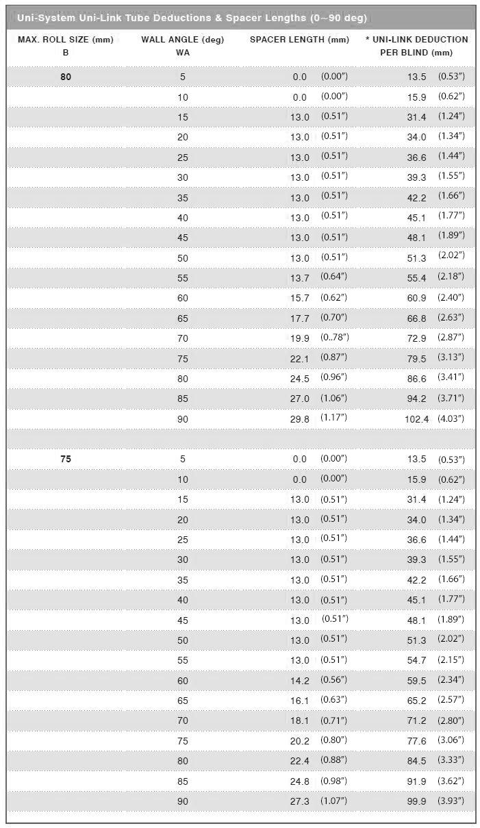
11 SECTION 3 UNI-LINK INSTALLATION PART A CALCULATE BLIND SIZE BASED ON INSTALLATION SPACE UNI LINK DEDUCTIONS ROLLEASE ACMEDA recommends the distance between the wall & foot of Uni-System brackets (C) to be 15mm (0.59 ) The table specifing the Tube Deductions (A) is based on C = 15mm (0.59 ) If C is other than 15mm (0.59 ) please use the electronic calculations to retrieve the accurate Tube Deduction (A). 1. Measure the Wall Lengths (W1 & W2) & the Wall Angle (WA) where the Uni-Link Joint will be used. 2. Calculate the Maximum Roll Size (B) required. Maximum Roll Size is determined by the maximum drop desired and the fabrics thickness. (Refer to Blind Drop Calculations for further information). 3. Calculate the Tube Deduction (A) & Spacer Length required. (Refer to Uni-System Uni-Link Tube Deductions & Spacer Lengths for further information). 4. Taking into consideration the deductions at the other end of the tubes for the Motor End / Idler End / Intermediate Joint / Uni-Link Joint, cut tubes to desired length. 5. Using the foot of the Uni-System brackets as a guide, mark on the ceiling where the bracket will be installed. Where D = 80mm (3.15 ) 2mm (0.08mm) + C. The centre hole in the foot of the bracket & the knuckle centre of the uni-joint is 14mm (0.55 ) from the centre line of the bracket. 6. Follow the relevant steps in the Instruction Manual to install the Uni-Link System. Page 3.7

12 DISTANCE TUBES DEDUCTIONS CHARTS Page 3.8
13 Page 3.9
14 Page 3.10
15 Page 3.11
16 PART B PREPARE BLINDS STEP 1 CUT BOTH UNI-LINK DISTANCE TUBES TO REQUIRED LENGTH (REFER TO DEDUCTIONS CHARTS) STEP 2 INSTALL UNI-LINK DISTANCE TUBES INSIDE CORRESPONDING UNI-LINK INTERMEDIATE RECEIVERS STEP 3 INSTALL UNI-LINK INTERMEDIATE RECEIVER 1 INTO TUBE OF BLIND 1. Page 3.12
17 STEP 4 INSTALL UNI-LINK INTERMEDIATE RECEIVER 2 INTO TUBE OF BLIND 2. PART C PREPARE INSTALLATION SPACE STEP 1 MEASURE AND MARK OUT INSTALLATION SPACE STEP 2 CALCULATE CORRECT ANGLE TO INSTALL INTERMEDIATE BRACKET STEP 3 CALCULATE MAXIMUM BLIND ROLL REQUIRED Page 3.13
18 PART D INSTALL BLIND STEP 1 INSERT HEXAGONAL SHAFT OF UNI-LINK INTERMEDIATE BRACKET INSIDE UNI-LINK INTERMEDIATE RECEIVER 1 STEP 2 WITH BLIND 1 FIXED TO ANOTHER FIXED BRACKET, MOUNT UNI-LINK INTERMEDIATE BRACKET TO CEILING WITH SCREWS. STEP 3 MOUNT BLIND 2 ONTO UNI-LINK INTERMEDIATE BRACKET Page 3.14

19 STEP 4 WITH BLIND 2 STILL ATTACHED TO UNI-LINK INTERMEDIATE BRACKET, ATTATCH BLIND 2 TO THE IDLER BRACKET PART E LEVELING BOTTOM RAIL (REQUIRED WHEN FABRIC LENGTH NOT EVEN) STEP 1 UNLOCK THE LOCKING RING Attach Adjuster Tool onto Locking Ring of Uni-Link Intermediate Receiver Rotate Adjuster Tool towards ceiling to unlock the Locking Ring NOTE: The locking ring will feel loose Page 3.15
20 STEP 2 OPEN CLUTCH AND ROTATE FABRIC Push Blind 2 against Intermediate Bracket, allowing the clutch too open, a click will be heard Rotate Blind 2 and align Fabric STEP 3 RE-LOCK RECEIVER ONTO DRIVE Rotate Adjuster Tool towards ground to lock the Locking Ring of the Uni-Link Intermediate Receiver, the Locking Ring will feel firm. Remove Adjuster. Page 3.16
EASY SPRING WAND INSTALLATION MANUAL. April 2018
 EASY SPRING WAND INSTALLATION MANUAL April 2018 CONTENTS April 2018 This manual is to be read in conjunction with the Product Specifications & Assembly manual SECTION NO. DESCRIPTION PAGE NO. SECTION 1
RB12 AERO - DUAL INSTALLATION MANUAL. February 2017
 RB12 AERO - DUAL INSTALLATION MANUAL February 2017 CONTENTS February 2016 This manual is to be read in conjunction with the Product Specifications & Assembly manual SECTION NO. DESCRIPTION PAGE NO. SECTION
INSTALL GUIDE AMBIENT BLINDS WINDSOR WIRE GUIDED SEMI RESTRAINED
 AMBIENT BLINDS WINDSOR WIRE GUIDED SEMI RESTRAINED INSTALL GUIDE CONTENTS September 2013 This manual is to be read in conjunction with the Product Specifications & Assembly manual SECTION NO. DESCRIPTION
R-SERIES FASCIA - 3&4 inch Chain Control PRODUCT SPECIFICATIONS
 R-SERIES FASCIA - 3&4 inch Chain Control PRODUCT SPECIFICATIONS CONTENTS SECTION A OVERVIEW 01 GENERAL SCHEMATICS...01 SYSTEM OPTIONS....02 COLOR OPTIONS......02 SECTION B SPECIFICATION IMAGES 03 ARCHITECTURAL
ZIPSCREEN EXTREME INSTALLATION MANUAL. February 2017
 ZIPSCREEN EXTREME INSTALLATION MANUAL February 2017 CONTENTS February 2017 This manual is to be read in conjunction with the Product Specifications & Assembly manual SECTION NO. DESCRIPTION PAGE NO. SECTION
Cassette Systems Fabrication & Installation Instructions Cassette 80, 100, 120
 Cassette Systems Fabrication & Installation Instructions Cassette 80, 100, 120 All Cassette Components 2 Cassette Systems Tools Needed page 4 Cassette 80 page 5-12 System Diagram- page 5 System Diagram-
LINK-BELT. These charts are not to be used for any other purpose. LOAD CHARTS for Use in CCO Written Examinations
 LOAD CHARTS for Use in CCO Written Examinations LINK-BELT TELESCOPIC BOOM CRANE SWING CAB (TLL) These charts have been adapted from the original manufacturer s charts for use in NCCCO Written Examinations.
LINK-BELT (Rough Terrain) LOAD CHART
 LOAD CHART") For Use in CCO Written Examinations LINK-BELT (Rough Terrain) LOAD CHART TELESCOPIC BOOM CRANE SWING CAB (TLL) These charts have been adapted from the original manufacturer s charts for use in CCO Written
For Use in CCO Written Examinations LINK-BELT (Rough Terrain) LOAD CHART TELESCOPIC BOOM CRANE SWING CAB (TLL) These charts have been adapted from the original manufacturer s charts for use in CCO Written
R-Series R-Series Fabrication
 R-Series R-Series Fabrication 1. CALCULATE THE EXACT WIDTH OF A SHADE - DIMENSION C a. Measure dimension ( A ), the distance between the outside of the brackets. INSIDE MOUNT Measure inside the frame.
PARTS BOOK CATALOG 3PT HITCH MOUNT HEADS SWING FLAIL-HEAVY DUTY MOWERS
 PARTS BOOK CATALOG 3PT HITCH MOUNT HEADS SWING FLAIL-HEAVY DUTY MOWERS DIAMOND MOWERS, Inc. 350 E 60 th St. North Sioux Falls, SD 57104 FOR WARRANTY CALL DIAMOND MOWERS DIRECT: 888-960-0364 OUR TECHNICIANS
User s guide M B
 User s guide M-9531-0297-04-B RGA22 RSLM scale high accuracy applicator linear encoder TABLE OF CONTENTS Page Introduction 1 RGA22 Applicator Kit 2 Section 1 Kit contents 2 1.1 Applicator body 2 1.2 Adaptors
AUTOMATE FT MOTOR INSTRUCTIONS
 AUTOMATE FT MOTOR INSTRUCTIONS AUTOMATE FT MOTOR [Ø45/5Nm/5rpm] P/N: RB24-6005-069005 DESCRIPTION AUTOMATE FT MOTOR is a multifunction tubular motor offering three different modes of operation; E-type
Installation Instructions Studio Makeup Station
 Installation Instructions Studio Makeup Station 30" and 36" Models 5-light 30" Studio Makeup Station 8-light 30" Studio Makeup Station 6-light 36" Studio Makeup Station 9-light 36" Studio Makeup Station
Clutch Operated Roller Shade with Fascia Installation Instructions
 Clutch Operated Roller Shade with Fascia Installation Instructions Tools Required for Installation: Power Drill & Drill Bits Installation Screws Level Pliers Measuring Tape Step #1 Bracket Installation
PARTS BOOK FLAIL HEADS 75 CUT 3PT HITCH SWING ARM
 PARTS BOOK FLAIL HEADS 75 CUT 3PT HITCH SWING ARM 5.10.18 DIAMOND MOWERS, LLC 350 E 60 th St. North Sioux Falls, SD 57104 FOR WARRANTY CALL DIAMOND MOWERS DIRECT: 888-960-0364 OUR TECHNICIANS WILL DIAGNOSE
Flushing Instruction
 Copyright WinGD. All rights reserved. By taking possession of the drawing, the recipient recognizes and honors these rights. Neither the who le nor any part of this drawing may be used in any way for construction,
ZF 6HP19X / 6HP21X 6HP19X 6HP21X. Automatic Transmission Spare Parts Catalog
 ZF 6HP19X / 6HP21X 6HP19X 6HP21X Automatic Transmission Spare Parts Catalog Warranty Information Warranty coverage for ZF passenger car transmission spare parts and kits covers the first 12 months after
MANITOWOC (Crawler Mount) LOAD CHART
 LOAD CHART") For Use in CCO Written Examinations MANITOWOC (Crawler Mount) LOAD CHART LATTICE BOOM CRAWLER CRANE (LBC) These charts have been adapted from the original manufacturer s charts for use in CCO Written Examinations.
For Use in CCO Written Examinations MANITOWOC (Crawler Mount) LOAD CHART LATTICE BOOM CRAWLER CRANE (LBC) These charts have been adapted from the original manufacturer s charts for use in CCO Written Examinations.
ZF 6HP26 / 6HP28 6HP26 6HP28. Automatic Transmission Spare Parts Catalog
 ZF 6HP26 / 6HP28 6HP26 6HP28 Automatic Transmission Spare Parts Catalog Warranty Information Warranty coverage for ZF passenger car transmission spare parts and kits covers the first 12 months after installation
Solar-Powered Battery Bank
 Solar-Powered Battery Bank 1 Page D I S C L A I M E R O F L I A B I L I T Y A N D W A R R A N T Y This publication describes the author s opinions regarding the subject matter herein. The author and publisher
ZF 6HP26X / 6HP28X 6HP26X 6HP28X. Automatic Transmission Spare Parts Catalog
 ZF 6HP26X / 6HP28X 6HP26X 6HP28X Automatic Transmission Spare Parts Catalog Warranty Information Warranty coverage for ZF passenger car transmission spare parts and kits covers the first 12 months after
PARTS BOOK FLAIL HEADS 75 CUT 3PT HITCH SWING ARM
 PARTS BOOK FLAIL HEADS 75 CUT 3PT HITCH SWING ARM 5.0.8 DIAMOND MOWERS, LLC 350 E 60 th St. North Sioux Falls, SD 5704 FOR WARRANTY CALL DIAMOND MOWERS DIRECT: 888-960-0364 OUR TECHNICIANS WILL DIAGNOSE
Spectralink 6000 Portfolio. Outdoor Base Station. Installation Guide. For Spectralink 6000 System
 Spectralink 6000 Portfolio Outdoor Base Station Installation Guide For Spectralink 6000 System 1725-86127-100 Rev: G Spectralink 6000 Portfolio Outdoor Base Station: Installation Guide Copyright Notice
600 SERIES STANDARD DUTY STRAIGHT TRACK INSTALLATION INSTRUCTIONS
 600 SERIES STANDARD DUTY STRAIGHT TRACK INSTALLATION INSTRUCTIONS PLEASE READ INSTRUCTIONS THOROUGHLY BEFORE BEGINNING. A. BI-PARTING TRAVEL 1. Before raising track into position, determine location of
Nota Conductor s Chair
 Assembly and Operation Instructions Nota Conductor s Chair CONTENTS Important User Information...........................2 General......................................2 Manufacturer.................................2
Mecho /5. An Installation Guide
 An Installation Guide Mecho /5 Special Order T:+1 (718) 729-2020 F:+1 (718) 729-2941 E: marketing@mechoshade.com Copyright 2011 MechoShade Systems, Inc. All rights reserved. All trademarks herein are owned
Probe Driver for Visual Plus 3. (c) , Saryna Technologies LLC/Advanced Inspection Technology
 , Saryna Technologies LLC/Advanced Inspection Technology") Probe Driver for Visual Plus 3 IMPORTANT Eddy Current Inspection VisualPlus 3 is an eddy current inspection tool to be used in conjunction with visual cylinder inspection. Eddy current inspection IS NOT
Probe Driver for Visual Plus 3 IMPORTANT Eddy Current Inspection VisualPlus 3 is an eddy current inspection tool to be used in conjunction with visual cylinder inspection. Eddy current inspection IS NOT
Use and Care Instructions: Youngman Telescopic Loft Ladder. Models: 2.6m and 2.9m. Safety
 Use and Care Instructions: Youngman Telescopic Loft Ladder Models: 2.6m and 2.9m Safety Please ensure you read the Safety section in this manual starting on page 4 before installing or using the equipment.
Clutch Operated FlexShade NEXD Window shade with heavy duty clutch and 3 hardware profile. Cassette option.
 INSTRUCTIONS INSTALLATION & OPERATION Overview - FlexShade Components Idler 1¼ Roller with Spline Atachment Clutch TOOLS REQUIRED Clutch PENCIL POWER DRILL Idler 1 Eliptical Hem Bar TAPE MEASURE LEVEL
Do-It-Yourself Battery Pack
 Do-It-Yourself Battery Pack 1 Page D I S C L A I M E R O F L I A B I L I T Y A N D W A R R A N T Y This publication describes the author s opinions regarding the subject matter herein. The author and publisher
RECHARGE STATION OPERATION MANUAL. Version
 RECHARGE STATION OPERATION MANUAL Version 1.0-0712 2014 by VirTra Inc. All Rights Reserved. VirTra, the VirTra logo are either registered trademarks or trademarks of VirTra in the United States and/or
VAG-ID.RU Ремонт АКПП ZF 5HP19. Automatic Transmission Spare Parts Catalog
 ZF 5HP19 Automatic Transmission Spare Parts Catalog Warranty Information Warranty coverage for ZF passenger car transmission spare parts and kits covers the first 12 months after installation in the vehicle,
62 Deck Idler Kit High Speed
 Part No. 00 FORM NO. -899 6 Deck Idler Kit High Speed For Model 70 Serial No. 99000 to 99000 For Model 7 Serial No. 9900 to 99000 INSTALLATION INSTRUCTIONS Loose Parts Note: Use the chart below to identify
Trackstar Motorized Folding Shade Installation Instructions
 Trackstar Motorized Folding Shade Installation Instructions Thank you for purchasing your new Trackstar folding shade. It has been custom-made from the highest quality materials to the dimensions you specified.
Installation InstructionS RB 500 Manual Roller Shades Heavy Duty Clutch Coupled Fascia Series-Coupled Unit...
 Installation InstructionS RB 500 Manual Roller Shades Heavy Duty Clutch Coupled Fascia 5-37 Series-Coupled Unit... Installation b a c Install the clutch bracket and intermediate bracket first. a) recess
MicroGuard 510 Retrofit Rated Capacity Indicator System. Calibration and Testing for:
 Greer Company Page 1 of 27 MicroGuard 510 Retrofit Rated Capacity Indicator System Calibration and Testing for: Machine Model Serial Number Tester Date Greer Company Page 2 of 27 Notice This document and
How to Install a Garage Door Opener
 How to Install a Garage Door Opener While installing a garage door opener is a relatively straightforward project, the installation process is too detailed - and too manufacturer-specific - to be covered
PARTS BOOK ROTARY HEADS 40 CUT EXCAVATOR MOUNT
 PARTS BOOK ROTARY HEADS 40 CUT EXCAVATOR MOUNT 5.10.18 DIAMOND MOWERS, LLC 350 E 60 th St. North Sioux Falls, SD 57104 FOR WARRANTY CALL DIAMOND MOWERS DIRECT: 888-960-0364 OUR TECHNICIANS WILL DIAGNOSE
Installation Instructions
 Roller & Roman Shades Lifting Systems Cassette and Sure-Lift EZ Lift Cordless EZ Pull Standard and Cassette R-Series Clutch SL-Series Clutch Spring Roller Fascias and Valances 3, 4 Flat and 4 Curved Fascia
TABLE OF CONTENTS 10.0 LIMITED WARRANTY
 10.0 LIMITED WARRANTY ELECTROMATIC Equipment Co., Inc. (ELECTROMATIC) warrants to the original purchaser that this product is of merchantable quality and confirms in kind and quality with the descriptions
PM - Projector Mount System
 Installation Instructions PM - Projector Mount System Design Highlights -Beautiful Anodised Aluminium Finish -Complete Lead-Screw Adjustment of All Pitches of Angle -Range of Fixed and Telescopic Poles
Installation, Operating and Maintenance Instructions Retractable Door / Art.-Nr.:
 Installation, Operating and Maintenance Instructions Retractable Door 06.2008 / Art.-Nr.: 1 818 024 ENGLISH CONTENTS PAGE 1 SAFETY REQUIREMENTS 3 1.1 Symbols and key words used 3 1.2 Designated use 3 1.3
Skyline 4 Fascia Fabrication & Installation Instructions
 Components Needed Page 2 Tools Needed Page 2 System Diagram Page 3 Instructions Step 1: Install Brackets Page 4 Step 2: Install Pre-assembled Shade Page 4 Step 3: Install Fascia Clip Page 4 Step 4: Cut
VW Arc-Weldable Strain Gauge
 VW Arc-Weldable Strain Gauge 52640399 Copyright 2002 Slope Indicator Company. All Rights Reserved. This equipment should be installed, maintained, and operated by technically qualified personnel. Any errors
QUANTUM LIGHT LIFT ROLLER BLIND SYSTEM
 QUANTUM LIGHT LIFT ROLLER BLIND SYSTEM Product Information QUANTUM LIGHT LIFT OPERATING SYSTEM An Innovative Chainless Operating Roller Blind System Designed for optimum Child Safety 1. UNIQUE LIGHT LIFT
Soil Strainmeter. Copyright O 1996 Slope lndicator Company All Rights Rese~ved.
 Soil Strainmeter This equipment should be installed. maintained. and operated by technically-qualified personnel. Any errors or omissions in data, or its interpretations, are not the responsibility of
Digital Remote Wheels DRW-1
 Digital Remote Wheels DRW-1 USER MANUAL Date 01.12.2018 2 Imprint Imprint Copyright 2018 Arnold & Richter Cine Technik GmbH & Co. Betriebs KG. All rights reserved. No parts of this document may be reproduced
MODEL PS-4 DIGITAL PORTION SCALE
 MODEL PS-4 DIGITAL PORTION SCALE OWNER S MANUAL CARDINAL SCALE MFG. CO. 8528-M317-O1 Rev A 203 E. Daugherty, Webb City, MO 64870 USA 07/05 Ph: 417-673-4631 Fax: 417-673-2153 www.detectoscale.com Technical
FRAME - REAR PARTS AND YEAR GUIDE
 & FRAME - REAR PARTS AND YEAR GUIDE IDENTIFING PARTS 12 th September 2010 BY John Ready CONTENTS 1.1. ABBREVIATIONS... Error! Bookmark not defined. 1.2. DISCLAIMER... Error! Bookmark not defined. 1.3.
Mechanical Spiral Sensor
 Installation Manual Model 6005-1 Mechanical Spiral Sensor No part of this instruction manual may be reproduced, by any means, without the written consent of Geokon, Inc. The information contained herein
PARTS BOOK CATALOG 3PT HITCH MOUNT HEADS ROTARY MOWERS PTO DRIVE
 PARTS BOOK CATALOG 3PT HITCH MOUNT HEADS ROTARY MOWERS PTO DRIVE DIAMOND MOWERS, Inc. 350 E 60 th St. North Sioux Falls, SD 57104 FOR WARRANTY CALL DIAMOND MOWERS DIRECT: 888-960-0364 OUR TECHNICIANS WILL
ZF 6HP26A 61 6HP26A 61. Automatic Transmission Spare Parts Catalog
 ZF 6HP26A 61 6HP26A 61 Automatic Transmission Spare Parts Catalog Warranty Information Warranty coverage for ZF passenger car transmission spare parts and kits covers the first 12 months after installation
Wenger Corporation 2011 Printed in USA 08/11 Part #158E006-02
 Owner s Manual Conductor s Podium COntents Warranty.......................................... 2 Important User Information............................ 2 General....................................... 2
Assembly instructions PRORUNNER mk1 2
 Assembly instructions PRORUNNER mk1 Version 0.1 / 01-JUN-2013 Copyright Qimarox B.V. All rights reserved. No part of this document may be copied, stored in a database and/or published by means of printing,
Pre-Installation Guide Performer
 Pre-Installation Guide Performer Contents Structural Requirements... 1 Dental Patient Chair Interface Requirement... 1 Utility Requirements... 1 Utility Specifications... 2 Electrical Ratings... 3 Shipping
Rollstar Shade Installation Instructions
 Rollstar Shade Installation Instructions All Lifting Systems Inside or Outside Mount Thank you for purchasing your new Rollstar shade. It has been custom-made from the highest quality materials to the
Installation Manual uniflow Gen. Budget Connector for ibos
 uniflow Gen. Budget Connector for ibos Installation Manual uniflow Gen. Budget Connector for ibos Product Version: 1.0 Version of this manual: 1.0.8 2016 Inepro B.V. All rights reserved uniflow Gen. Budget
Overhead Twin Line Irrigation Installation Guide COM 2 Copyright First Tunnels Ltd 2012.
 www.firsttunnels.co.uk/quality Overhead Twin Line Irrigation Installation Guide COM 2 Copyright First Tunnels Ltd 2012. Warnings General Please keep children and pets away from the work area. If any holes
OnBoard Drum Major Podium
 Assembly and Owner s Manual OnBoard Drum Major Podium CONTENTS CONTENTS................................................................................. 1 SAFETY...................................................................................
PARTS BOOK FLAIL HEADS 90 SIDE MID-MOUNT
 PARTS BOOK FLAIL HEADS 90 SIDE MID-MOUNT 5.0.8 DIAMOND MOWERS, LLC 350 E 60 th St. North Sioux Falls, SD 5704 FOR WARRANTY CALL DIAMOND MOWERS DIRECT: 888-960-0364 OUR TECHNICIANS WILL DIAGNOSE YOUR SITUATION
Mobile TV Mount Stand with Hydraulic Height Adjustment Model: DMS-172
 Mobile TV Mount Stand with Hydraulic Height Adjustment Model: DMS-172 Instruction Manual Images may be different from actual product Disclaimer It is Dyconn s intention to have all the correct information
Fuller Mid-Range Transmissions TRDR0100
 Driver Instructions Video Instruction Available Instructional videos are available for download at no charge at roadranger.com Videos are also available for purchase. To order, call 1-888-386-4636. Ask
Yamaha Viking Rackzilla Install/Removal
 2014-15 Yamaha Viking Rackzilla Install/Removal Kit Numbers: 8001850, 8001790 Full refund will NOT be granted to any kits that are damaged, scratched, or altered in any fashion. Kit Contents: Part Number
AMERICAN. These charts are not to be used for any other purpose. LOAD CHARTS for Use in CCO Written Examinations
 LOAD CHARTS for Use in CCO Written Examinations AMERICAN LATTICE CRAWLER CRANE (LBC) These charts have been adapted from the original manufacturer s charts for use in NCCCO Written Examinations. These
ECE 44 Seat Cushions (O.K) User Manual
 User Manual") ECE 44 Seat Cushions (O.K) User Manual O.KC User Manual, ECE 44 Seat Cushions (O.K), Rev A Page 1 of 8 For information on Humanetics products, please visit our web site at www.humaneticsatd.com or contact:
ECE 44 Seat Cushions (O.K) User Manual O.KC User Manual, ECE 44 Seat Cushions (O.K), Rev A Page 1 of 8 For information on Humanetics products, please visit our web site at www.humaneticsatd.com or contact:
PARTS BOOK ROTARY HEADS 50 CUT, INDIRECT DRIVE BOOM MOUNT
 PARTS BOOK ROTARY HEADS 50 CUT, INDIRECT DRIVE BOOM MOUNT 5.10.18 DIAMOND MOWERS, LLC 350 E 60 th St. North Sioux Falls, SD 57104 FOR WARRANTY CALL DIAMOND MOWERS DIRECT: 888-960-0364 OUR TECHNICIANS WILL
Operating Instructions
 DuroSite & SafeSite Area Light with Adapters Important Information: These instructions contain safety information, read and follow them carefully. Dialight will not accept any responsibility for injury,
Installation Instructions Lockey TB 250/450/650 Plus Hydraulic Pedestrian Gate Closer (with hydraulically adjustable closing speed)
") Installation Instructions Lockey TB 250/450/650 Plus Hydraulic Pedestrian Gate Closer (with hydraulically adjustable closing speed) The Lockey TB 250/450/650 Plus Pedestrian Gate Closer is a fully featured
Installation Instructions Lockey TB 250/450/650 Plus Hydraulic Pedestrian Gate Closer (with hydraulically adjustable closing speed) The Lockey TB 250/450/650 Plus Pedestrian Gate Closer is a fully featured
Holley A/C Bracket System Part Number
 Holley A/C Bracket System Part Number 20-141 Table of Contents: Introduction:... 2 Crank Pulley Belt Alignment Determination:... 3 Overview of Parts Required (but NOT included with 20-141 accessory drive
PARTS BOOK ROTARY HEADS 60 BOOM MOUNT SERIAL #XXXXX+ DIAMOND MOWERS, LLC 350 E 60 th St. North Sioux Falls, SD 57104
 PARTS BOOK ROTARY HEADS 60 BOOM MOUNT SERIAL #XXXXX+ DIAMOND MOWERS, LLC 350 E 60 th St. North Sioux Falls, SD 57104 FOR WARRANTY CALL DIAMOND MOWERS DIRECT: 888-960-0364 OUR TECHNICIANS WILL DIAGNOSE
ROMANS. SS38 Chain Control
 ROMANS SS8 Chain Control JULY 2015 ROLLEASE ACMEDA EUROPE ROMANS SS8 CHAIN CONTROL SYSTEM SYSTEM OVERVIEW SS8 5 5 1 4 2 2 COLOUR RANGE pure white PRODUCT OPTIONS SS8 SLIM SPOOL 2b SS8 SPRING LOADED MOUNTING
IMPORTANT INSTRUCTIONS FOR OPERATION & MAINTENANCE OF
 IMPORTANT INSTRUCTIONS FOR OPERATION & MAINTENANCE OF CONVEYORS EASIKIT 300 EASIKIT 450 EASIKIT 600, 900, 1200 & 1500 The manufacturer does not accept responsibility for any loss, damage to other equipment,
Declaration of Conformity
 Declaration of Conformity We, Manufacturer: Spartanics Ltd. 3605 Edison Place Rolling Meadows, Illinois 60008 Phone: 847-394-5700 Fax: 847-394-0409 USA ENGLISH declare under our sole responsibility that
PARTS BOOK ROTARY HEADS 60 CUT COMBO MID-MOUNT
 PARTS BOOK ROTARY HEADS 60 CUT COMBO MID-MOUNT 5.0.8 DIAMOND MOWERS, LLC 350 E 60 th St. North Sioux Falls, SD 5704 FOR WARRANTY CALL DIAMOND MOWERS DIRECT: 888-960-0364 OUR TECHNICIANS WILL DIAGNOSE YOUR
Content Page passtptest.com
 All rights reserved. No part of this book shall be reproduced, stored in a retrieval system, or transmitted by any means, electronic, mechanical, photocopying, recording, or otherwise, without written
CHAPTER 10 PARKING AND MOORING
 CHAPTER 10 PARKING AND MOORING P/N 135A-970-100 Chapter 10 REVISION ~ Page 1 of 12 Copyright 2009 All rights reserved. The information contained herein is proprietary to Liberty Aerospace, Incorporated.
APRICUS PUMP STATION TECHNICAL GUIDE
 APRICUS PUMP STATION TECHNICAL GUIDE A technical reference for the Apricus Pump Station for installers Version 1.1 The customer agrees to and accepts all related charges incurred as a result of a warranty
Mazda North American Operations Irvine, CA
 Service Bulletin Mazda North American Operations Irvine, CA 92618-2922 Subject: VARIABLE VALVE TIMING (VVT) NOISE AND/OR TIMING CHAIN NOISE Bulletin No: 01-012/12 MULTI-MODEL (L3 TURBO) - VARIABLE VALVE
Holley Accessory Drive System Part Number Table of Contents
 Holley Accessory Drive System Part Number 20-136 Table of Contents Introduction:... 2 Crank Pulley Belt Alignment Determination:... 3 Overview of Parts Required (but NOT included with 20-136 accessory
Assembly Instructions Signature Choral Riser 3-Step Model
 Assembly Instructions Signature Choral Riser 3-Step Model Contents Important User Information...........................2 General...2 Manufacturer...2 Intended Use...2 Warranty...2 Safety Precautions.................................3
CALMETRIX INC. PHESO CONCRETE RHEOMETER
 PHESO USER MANUAL CALMETRIX INC. PHESO CONCRETE RHEOMETER USER MANUAL 2 Calmetrix Pheso User Manual 2018 Calmetrix Inc. All rights reserved IMPORTANT SAFETY RULES Exercise caution when handling the Pheso
5-Slot and 2-Slot Panels Installation Guide
 5-Slot and 2-Slot Panels Installation Guide Disclaimer Control4 makes no representations or warranties with respect to this publication, and specifically disclaims any express or implied warranties of
Holley Accessory Drive Kit Part Number
 Assembly Instructions Holley Accessory Drive Kit Part Number 20-133 Table of Contents Parts List:... 2 Passenger s Side Bracket Installation:... 3 A/C Compressor Installation:... 4 Idler & Tensioner Installation:...
)LUHQ]H installation manual
![)LUHQ]H installation manual](/thumbs/87/96494264.jpg ")LUHQ]H installation manual") installation manual All information contained in this document was provided by the manufacturer of the components for this model. As a fabricator, Retractableawnings.com claims no liability with respect
installation manual All information contained in this document was provided by the manufacturer of the components for this model. As a fabricator, Retractableawnings.com claims no liability with respect
Holley Accessory Drive Kit Part Number &
 Holley Accessory Drive Kit Part Number 20-156 & 20-162 Table of Contents A/C side not included with 20-156 Introduction:... 2 Crank Pulley Belt Alignment Determination:... 3 Overview of Parts Needed (but
B- and C- Series Ranges
 INSTALLATION INSTRUCTIONS for An AUTOMATIC OVEN PILOT LIGHT & GAS VALVE SHUTOFF SYSTEM for INCLUDING MODELS: B- and C- Series Ranges Models B & BZ Model 90-C Model 61-C Model 41-C Every effort to assure
We ve doubled our technology.
 U N I V E R S A L We ve doubled our technology. The modularity of the new RollEase Universal 5 Fascia System TM accommodates one or two roller shades and offers a variety of different configurations. Enjoy
Assembly Instructions. Holley Accessory Drive Kit Part Number
 Assembly Instructions Holley Accessory Drive Kit Part Number 20-131 Table of Contents Parts List:... 2 Driver s Side Bracket Installation:... 3 Power Steering Pump Installation:... 4 Idler Pulley Installation
SEALING DIP CAP INSTALLATION GUIDE
 SEALING DIP CAP INSTALLATION GUIDE The information in this publication is provided for reference only. While every effort has been made to ensure the reliability and accuracy of the information contained
PARTS BOOK ROTARY HEADS 60, INDIRECT DRIVE CABLE MID-MOUNT
 PARTS BOOK ROTARY HEADS 60, INDIRECT DRIVE CABLE MID-MOUNT DIAMOND MOWERS, LLC. 350 E 60 th St. North Sioux Falls, SD 57104 FOR WARRANTY CALL DIAMOND MOWERS DIRECT: 888-960-0364 OUR TECHNICIANS WILL DIAGNOSE
PARTS BOOK ROTARY HEADS 72 CUT SKID-STEER MOUNT
 PARTS BOOK ROTARY HEADS 72 CUT SKID-STEER MOUNT DIAMOND MOWERS, LLC 350 E 60 th St. North Sioux Falls, SD 57104 FOR WARRANTY CALL DIAMOND MOWERS DIRECT: 888-960-0364 OUR TECHNICIANS WILL DIAGNOSE YOUR
INSTRUCTION MANUAL. Pacific Self-locking Beam Trolleys Pacific Adjustable Angle Clamps Pacific Top Girder Clamps
 INSTRUCTION MANUAL Pacific Self-locking Beam Trolleys Pacific Adjustable Angle Clamps Pacific Top Girder Clamps IMPORTANT Please read this instruction manual before using these products. This manual contains
Installation Instructions Roller Shades. 451 N. Cota St, Corona, CA
 Installation Instructions Roller Shades 451 N. Cota St, Corona, CA 92880 800-281-3013 Installing the Shade: Installing Your New Roller Shades Please take a moment to review the contents of your parts package.
FLEX CONNECTOR HEAT SHRINK SLEEVE INSTALLATION GUIDE
 FLEX CONNECTOR HEAT SHRINK SLEEVE INSTALLATION GUIDE The information in this publication is provided for reference only. While every effort has been made to ensure the reliability and accuracy of the information
3540 Series Short Backset Mortice Locks. ASSA ABLOY, the global leader in door opening solutions 2
 Short Backset Mortice Locks ASSA ABLOY, the global leader in door opening solutions 2 Contents 3540 Series Short Backset Motice Locks 1 3540 Series General Information 2 3540 Short Backset Mortice Deadlock
 D I S C L A I M E R O F L I A B I L I T Y A N D W A R R A N T Y This publication describes the author s opinions regarding the subject matter herein. The author and publisher are not rendering advice or
Installation Operation Care
 Installation Operation Care Standard Clutch CONTENTS Getting Started: Product View... 1 Tools and Fasteners Needed... Installation: Mounting Types and Window Terminology... Mount the Installation Brackets
Door Restrictor Assembly. Model R2
 Door Restrictor Assembly Model R2 Every attempt has been made to ensure that this documentation is as accurate and up-to-date as possible. However, Vertical Express assumes no liability for consequences,
Fiberglass Rod Extensometer
 Fiberglass Rod Extensometer 51836499 Copyright 2002 Slope Indicator Company. All Rights Reserved. This equipment should be installed, maintained, and operated by technically qualified personnel. Any errors
Standard Roller Shades
 Standard Roller Shades Dual Link System Multi Link System Double Bracket System Installation & Operating Instructions New pictures TC01-06.2011 TABLE OF CONTENTS Getting Started: Mounting Types...1 Installation