IMPORTANT INSTRUCTIONS FOR OPERATION & MAINTENANCE OF
|
|
|
- Edith Lawrence
- 5 years ago
- Views:
Transcription


1 IMPORTANT INSTRUCTIONS FOR OPERATION & MAINTENANCE OF CONVEYORS

2 EASIKIT 300 EASIKIT 450 EASIKIT 600, 900, 1200 & 1500 The manufacturer does not accept responsibility for any loss, damage to other equipment, injury to personnel or any other circumstance resulting from the use of our equipment. All rights reserved. No part of this publication may be reproduced, stored in a retrieval system, or transmitted in any form or by any means - electronic, mechanical, photocopying, recording or otherwise - unless the permission of the publisher has been given beforehand. All specifications are subject to change without notice Page 2
3 OPERATING INSTRUCTIONS WARNING! ISOLATE AND LOCK-OFF SUPPLY BEFORE INSPECTION If you cannot lock off the power supply, unplug the conveyor from the starter or transformer. Visually inspect all external electrical connections. Check for materials jammed between the belt and conveyor structure. Check for material build up on any of the rollers or side guides. Ensure area under and adjacent to, the loading/tail section is clear of debris. Check external belt scraper for tension (if fitted). Inspect belt & clip joints for damage and wear, also check the tension of the belt, if you find any damage to the belt or joints, inform our service department immediately so it can be dealt with ASAP to avoid unnecessary & expensive damage. If the conveyor is on stands or scaffolding, check the tightness of all bolts or scaffold clips. Clear out any debris or build-up of material from the back and underside of the loading area (under the tail section). Inspect the condition of the loading boot rubber skirts. Check E-stops are operating (if fitted). Check head guard is fitted securely (if applicable). Check all safety hoarding is in place. (where applicable) Conveyor must be hoarded/guarded off over any public access for its entire length; access to any ramps/gantries should be closed during this operation. Any hoarding fitted should be cut to give access to the motor and head tracking points so any necessary maintenance work can be carried out, the underside of the hoarding should be made removable, to allow for any clearing of material build up. Visually check on all nuts & bolts on rollers and feed hoppers ANY DEFECTS SHOULD BE REPORTED IMMEDIATELY Page 3
4 Start-up procedure Switch on electrical supply (Either by switching on the transformer or by plugging in the power lead). Give audible warning and check the discharge area of the conveyor before turning on the conveyor. Press the green start button. Observe the operation and tracking of the belt. (For adjusting points, see diagrams on page 5 for the type of conveyor you are using) Load conveyor steadily and commence operations. Loading REMEMBER! YOU ARE FEEDING A MOVING BELT, SO FEED ACCORDINGLY AND THE CONVEYOR WILL WORK VERY WELL. OVERLOAD AND YOU WILL CAUSE BREAKDOWNS WHICH IN TURN WILL COST YOU MONEY. Conveyor only to be loaded at the feed hopper or at designated loading points. Loading only to commence once the conveyor has been started. Feed hoppers to be fed evenly and steadily. When loading steeper conveyors some rollback will incur. Care must be taken to ensure injury cannot be caused to the operator/loader by large items coming off the end of the conveyor. OVERLOADING WILL INEVITABLY CAUSE JAMMING AND BREAKDOWNS, THEREFORE CAUSING DOWNTIME ON SITE. Shut down procedure Ensure belt is emptied, except in emergency stop conditions. Press the stop button Then switch off the power at the control isolator switch on contractors power supply. Transformers should be switched off at the end of the working day. Page 4


5 GENERAL MAINTENANCE For more detailed Routine maintenance see Pages 9 20 Keep the conveyor clean, particularly under and around the loading section. Belt Check belt tension and adjust if necessary by evenly tightening adjusting nuts situated either side of the conveyor tail section. (See details below) The correct tension is the minimum required to maintain drive to the belt. OVER TENSIONING WILL CAUSE BREAKDOWNS THEREFORE DOWNTIME! Gearbox Lubricated for life; check oil seals on output shaft for leaks. If the gearbox starts leaking please contact our service department immediately. EK300 TENSIONING &TRACKING POINTS EK450 TENSIONING & TRACKING POINTS THE HEAD UNIT TRACKING IS IDENTICAL ON THE EK450 EK1500 EK600/900/1200/1500 TENSIONING & TRACKING POINTS Page 5
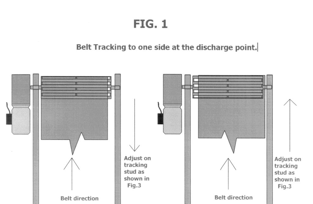
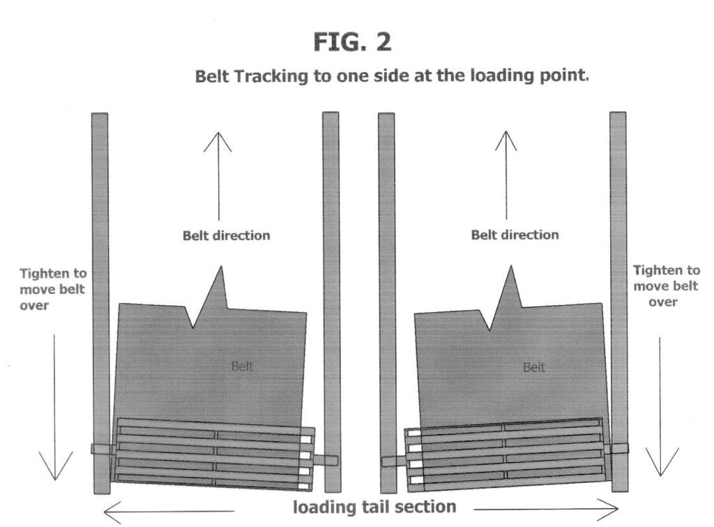
6 TROUBLE SHOOTING Belt tracking over to one side at the tail section STOP the conveyor and ISOLATE POWER SUPPLY. Remove the feed boot, release the tension off of the belt and ensure there is no build up around the tail drum or any stones trapped between the drum and framework, then test to ensure the drum runs freely. Also carry out visual check on bearing condition (any play or noise) and if you find there is a problem contact our service department who will arrange for a visit. If no problem is found, tension the belt and connect the power and switch on, whilst the belt is running check the tracking and adjust as necessary to centralize the belt on the roller (see Fig 2 on page 8), switch off and refit the feed boot. Belt tracks over at the head section STOP the conveyor and ISOLATE POWER SUPPLY. Check the head unit for any build up around the head drum or rollers and clear if found. Loosen the four locating bolts (see diagrams on page 5, do not completely undo the nuts) and make the necessary adjustments to centralize the belt (see Fig 1 on page 8), start the conveyor and check the position of the belt and make any final adjustments, retighten the four locating bolts and lock off the adjusting stud. Drive operating but the belt is stationary ISOLATE POWER SUPPLY. Check moving parts are free from obstruction. Tension the belt by adjusting the tension bolts evenly on the tail section. (See diagrams on Page 5) Restore the power and institute the start-up, check belt tracking and adjust as necessary. Page 6
7 Motor cuts out ISOLATE POWER SUPPLY. Check that nothing has jammed any moving parts, particularly behind loading back guard. Contact our service department immediately. UNDER NO CURCUMSTANCE SHOULD YOU REPEATEDLY TRY TO START THE CONVEYOR, AS THIS WILL CAUSE SERIOUS MOTOR DAMAGE! Starter does not work ISOLATE POWER SUPPLY. Check that the main fuse has not tripped, check the power lead to ensure that no damage has occurred, unplug the lead from the power socket, a competent electrician could check for loose or disconnected wires within the plugs and sockets. If after this has been done and you have reconnected the power it still fails to work, contact our service department for assistance. Starter clicks but motor does not work ISOLATE POWER SUPPLY. Check the plug from starter to motor for any loose wires, check the wire for any damage. If damage has occurred or there is no apparent damage, contact our service department for assistance. Material jammed in conveyor under the receiving hopper ISOLATE POWER SUPPLY to the conveyor. If the item cannot be removed easily contact our service department for assistance. Noise If the conveyor starts to make any form of noise other than the normal operational noise, STOP AND ISOLATE the conveyor and check for something jamming the conveyor. If you find anything, remove it, if the noise persists, contact our service department for assistance. Page 7
8 Page 8
9 ROUTINE MAINTENANCE Routine maintenance checks are very important in maintaining the full useful working life of your Easikit conveyor. A regular maintenance program paying due attention to all the components itemised in this Routine Maintenance section will reduce the likelihood of break-down and costly downtime. Frequency of checks will depend on conveyor usage i.e. material being handled, hours worked per day etc. Checks are recommended at regular intervals depending on the amount of working hours that the conveyor is being used for. A main feature in extending the life of your conveyor is thorough cleaning at regular intervals to prevent material build-up particularly around the feed and discharge points (good house-keeping is essential). THERE ARE REGULAR MAINTENANCE CHECKS THAT MUST BE CARRIED OUT: - 1. EVERY WEEK (or 60 hours) 2. EVERY MONTH (or 250 hours) 3. EVERY 3 MONTHS (or 750 hours) 4. ANNUALLY (or 3000 hours) WARNING! DOWN TIME COSTS MONEY, LOOK AFTER YOUR EASIKIT CONVEYOR! Page 9
10 ROUTINE MAINTENANCE CHECK LIST 1.1. MATERIAL HANDLING It is very important to ensure that your conveyor is operating within its capacity. If you are in doubt as to the capacity, please consult your conveyor supplier. Overflowing and excessive quantities of material on the belt will lead to material build up in unnecessary areas that will in turn cause damage to your conveyor MATERIAL FEED POINTS Inspect the feed points of the conveyor and ensure that material is feeding correctly onto the belt and that there is no over flow or spillage onto the surrounding area. Any material build up will create a hazard which will develop into a potential for conveyor failure and cause subsequent down time RUBBER BELT Rubber belt and belt joints are classed as wear items and not covered under the manufacturer s warranty. Regular checking of the belt, joints and tracking will help prevent any unnecessary damage to these items and to the conveyor framework. Particular attention will need to be given to metal clip joints (where supplied) as wear to the underside of the joint will not readily be noticeable from a surface visual inspection BELT SCRAPERS A regular visual check & clean of scrapers with necessary adjustments is essential to ensure their ongoing efficient operation. Maintenance checks should be carried out as per the routine maintenance schedule on page 9. The blades are wear items and not covered by the manufacturer s warranty. Where standard Easikit primary & secondary scrapers have been supplied, the blade is reversible and can be turned around to maximize usage ROLLERS Intermediate top troughing rollers and return rollers will need to be checked regularly for free rotation and any excessive wear. These have sealed for life bearings and will need to be kept free from any material build up. Do not use thin spray lubricants (i.e. WD-40) as these will wash out the pre-greased bearings. If external lubrication is needed, this should be done with a spray lubricant grease (avoid any contact with the rubber belt) HEAD UNIT The Head Unit should be should be checked as per the maintenance schedule and visually assessed to ensure that the drum is functioning correctly and that the lagging is not excessively worn. The Head Drum and its mountings should be secure and in alignment with the conveyor and the motor mounting bracket secure to both conveyor frame and gearbox. Checks should be carried out to the inside of the side mounting plates to ensure that the belt has not been running out of alignment causing the edge of the moving belt to rub and wear the plates. Page 10
11 1.7. TAIL UNIT The Tail Unit should be checked as per the maintenance schedule and visually assessed to ensure that it is functioning correctly and that the drum is clean with no excessive build up of material around the drum and that it is running in the bearings correctly. This can be accessed by removing the tail drum guard (and the hopper if possible). Ensure that the tensioning stud bars each side are clean and operational and that the side clamps are tightly secured. The tensioning stud bars will benefit from a periodic light greasing with a multipurpose grease TOGGLE & JOINT CHECK All conveyor section connecting toggles & bolts should be checked periodically as per the maintenance schedule. This will involve manually lifting of the conveyor belt and visually and mechanically checking that they are secure and tight MOTOR & ELECTRICS Carry out a regular visual check to ensure there are no obvious signs of wear or damage to the motor and supply cables. Any wear or damage in these areas should be reported immediately to a competent electrician to carry out further investigation and any necessary repair work GEARBOX UNITS All gearboxes supplied are maintenance free as they are lubricated for life at the factory and the oil should not require changing. Visually inspect for damage BEARINGS All external bearings need to be inspected for any excessive wear and that they are secure to the conveyor frame and in clean condition. All these bearings will need grease lubrication regularly. The manufacturer s recommended lubricant is a high quality lithium based grease of 2-3 consistency. They will need to be checked as per the maintenance schedule. WARNING! DO NOT OVERGREASE BEARINGS TOP COVERS It is important that all top covers have been fitted as per the Easikit Instruction Manual and should be checked periodically as indicted in the maintenance schedule. The top covers should be removed when cleaning the conveyor. Whilst the covers are removed, they should be inspected thoroughly for any damage that may have occurred to both the covers and fixings. It is important that all fixings are securely tightened after refitting the covers. Page 11
12 1.13. BOTTOM COVERS It is important that all bottom covers have been fitted as per the Easikit Instruction Manual and should be checked periodically as indicated in the maintenance schedule. Remove the bottom covers following the instructions in the Easikit Instruction Manual in reverse order; you may not need to remove them completely as it is possible to remove only two bolts and hinge the covers down on the two remaining bolts at the opposite end. Ensure that all built up material is removed from the return belt area, paying particular attention to the return rollers that support the return belt. Ensure that the cage nuts are in good working order and inspect the covers thoroughly for any damage that may have occurred and then re-fit the covers back into position in the reverse order. It is important that all fixings are securely tightened after refitting the covers BELT TRACKING Belt tracking should be visually checked at both ends of the conveyor to ensure that the belt is running in the centre of the drums and not running to one side more than the other. You may need to remove any objects that obstruct your visual inspection. If the belt is running out of alignment follow the belt tracking procedure as set out in the Easikit Instruction Manual BELT TENSIONING To check the belt tension on you conveyor, first make sure that there is no load on the belt. Ensure that you are situated in a safe position prior to starting the conveyor to inspect the belt running and that you are able to visually see the head drive drum on start up of the conveyor. On start up, first check that there is no belt slippage on the drum. If the belt is not slipping, then repeat this check with the belt running under its normal working load. Should you experience any slipping of the belt at the drive drum, then increase the tension at the tail drum end by following the tracking and tensioning procedure as set out in the Easikit Instruction Manual HOPPER Inspect regularly as per the maintenance schedule to ensure that there is no material build up in the hopper and its surrounding area. Check thoroughly that there is no damage to the hopper. Clean and remove material as necessary. Check hopper rubbers for wear or damage and replace if required. (These are classed as wear items and not covered by the manufacturer s warranty). Ensure all fixings are secure and tightened SIDE GUIDES Side Guides need to be inspected periodically as per the maintenance schedule to ensure that they are fixed securely and that they are not damaged. These should be inspected to make sure that the side skirting that interfaces with the belt is not damaged and that it is sitting on top of the moving belt. This must be in its correct position as shown in the Easikit Instruction Manual. Ensure that all side guides are free from material build up around the support brackets and feed points etc. (Rubber skirts are classed as wear items and not covered under the manufacturer s warranty). Page 12
13 1.18. SUPPORT STANDS All support stands should be checked periodically that all fixings are tight and secure. Inspect all supports for any damage. Replace any damaged parts as necessary. Ensure that no extra weight loadings have been added to the support stands since the conveyor was originally specified AUTO GREASE UNITS If Auto Grease Units are fitted to your conveyor, these will need to be checked as per the maintenance schedule. It is important to familiarise yourself how much grease the unit is using between your inspections and ensure there will be sufficient grease to cover the conveyor running hours before your next check. If there is insufficient grease left, these should be changed and fitted as per the Easikit Instruction Manual. Replacement cartridges can be obtained from your conveyor supplier MOTION SENSORS If a Motion Sensor has been supplied with your conveyor this will need to be regularly inspected as per the Maintenance schedule. a) VISUAL INSPECTION - Check visually that the unit is performing mechanically and ensure that all fixings are secure and the unit is not damaged. b) MANUAL INSPECTION - To check manual operation of the sensor, belt tension will need to be released (follow the instructions in the Easikit Instruction Manual in reverse order) until the belt and the drive drum begins to slip and that belt movement has stopped. This should then activate the Sensor to shut down the electrical supply to the motor that will in turn isolate the power supply to the conveyor. Re-tension the belt as set out in the Easikit Instruction Manual. A competent electrician will also need to inspect the unit to ensure that it is still functioning with the electrical controls EMERGENCY GRAB WIRES & STOP STATIONS All Emergency Stop devices must be regularly checked as per the Maintenance Schedule to ensure they are functioning correctly. (i.e. activate and ensure the conveyor stops). All stop units and cabling should be checked visually for damage and that all fixings are secure. Any maintenance work required should be carried out by a qualified electrician MOBILE CONVEYORS It is important that all linch pins are inspected to ensure they are correctly positioned and the safety retaining pins are secure. Pneumatic tyres should be inspected regularly for damage, wear and that they are inflated with sufficient pressure as indicated on the tyre wall. Inspect hydraulics as per Section Page 13
14 1.23. RADIAL CONVEYORS Ensure the conveyor is operating correctly in its radial action and that the radial track line is clear and free from debris etc. It is important that all linch pins are inspected to ensure they are correctly positioned and the safety retaining pins are secure. Remove wheel covers and inspect wheel mounting shafts and bearings for any damage and wear. Drive shaft bearings should be greased. The manufacturer s recommended lubricant is a high quality lithium based grease of 2-3 consistency. Ensure motor mounting bracket is secure and replace covers and secure fixings. Inspect hydraulics as per Section Radial slewing anchor bearings will also need to be greased when required. Ensure ground fixing anchors are still secure and tight. Visually inspect electrical wiring and connections for any signs of damage. Any electrical maintenance work required should be carried out by a qualified electrician MOBILE & RADIAL HYDRAULICS Visually check that there are no leakages or damage at hose connections, along the hose length and the ram. Check safety linch pins are correctly inserted and retained. Try and elevate the conveyor to its maximum position. If the conveyor will not reach this position, it is an indication that there is insufficient hydraulic oil in the system. Next lower the conveyor to its lowest position, ensuring that the hydraulic ram is in its closed position. Proceed to add oil to the hydraulic pump as necessary CONVEYOR WASHDOWN Periodic washing and cleaning of your conveyor will be necessary to maintain its efficient operation. The manufacturers recommend the use of a high power water jet or similar (e.g. steam cleaner). Correct PPE should be worn when carrying out washing etc. Prior to undertaking any washing, the environment the conveyor is situated in should be considered and that no damage of surrounding items is likely to occur. Ensure there is adequate drainage prior to washing. Excessive material should be disposed of in a manner that will not cause damage to the environment. It will be necessary to remove conveyor covers to give access to the belt area (see Sections 1.12 & 1.13). Ideally the belt tension should be released allowing the belt to be raised to gain access to the inside of the conveyor frame. Particular attention and thorough washing will be required around the head and tail drum areas. WARNING! ENSURE ALL COVERS & GUARDS HAVE BEEN REPLACED PRIOR TO RE-STARTING YOUR CONVEYOR AND THAT ALL FIXINGS ARE TIGHT & SECURE DOCUMENTATION All maintenance should be documented accordingly in the section at the rear of this Service & Maintenance Schedule. Page 14
15 EASIKIT ROUTINE MAINTENANCE SCHEDULE Frequency Item Maintenance check Weekly Monthly 3 Monthly Annual or 60 hours or 250 hours or 750 hours or 3000 hours 1.1 Material Handling 1.2 Material Feed Points 1.3 Rubber Belt 1.4 Belt Scrapers 1.5 Rollers 1.6 Head Unit 1.7 Tail Unit 1.8 Toggle & Joint Check 1.9 Motor & Electrics 1.10 Gearbox Units 1.11 Bearings 1.12 Top Covers 1.13 Bottom Covers 1.14 Belt Tracking 1.15 Belt Tensioning 1.16 Hopper 1.17 Side Guides 1.18 Support Stands 1.19 Auto Grease Units 1.20 Motion Sensor - Visual Motion Sensor - Manual 1.21 Emergency Grab Wires 1.22 Mobile 1.23 Radial 1.24 Mobile & Radial Hydraulics 1.25 Conveyor Washdown 1.26 Documentation Contact your supplier for replacement parts. ROUTINE MAINTENANCE CONTRACTS Service contracts are available. Contact your supplier for details WARRANTY It is important that the Maintenance Schedule is adhered to in order to validate the manufacturer s warranty. Page 15
16 SERVICE HISTORY Page 16
17 SERVICE HISTORY Page 17
18 SERVICE HISTORY Page 18
19 SERVICE HISTORY Page 19
20 SERVICE HISTORY Page 20
21 SERVICE HISTORY PLEASE CONTACT YOUR SUPPLIER FOR FURTHER COPIES OF THIS MANUAL Page 21
MODULAR CONVEYOR SOLUTIONS. The conveyor of choice...for tomorrow
 MODULAR CONVEYOR SOLUTIONS The conveyor of choice......for tomorrow 2 Modular conveyors Our modular approach puts an end to expensive, bespoke conveyor installations that not only cost you valuable time,
Maintenance and Repair
 Maintenance and Repair WARNING ALWAYS shut off the engine, remove key from ignition, make sure the engine is cool, and disconnect the spark plug and positive battery terminal from the battery before cleaning,
INSTRUCTION MANUAL FOR MODEL PRC POWER ROLLER CONVEYOR
 INSTRUCTION MANUAL FOR MODEL PRC POWER ROLLER CONVEYOR - 1 - TABLEOFCONTENTS 1. OPERATION 3 1.1. GENERAL DESCRIPTION 3 1.2. OPERATION 3 1.2.1. GENERAL INSTRUCTIONS 3 2. MAINTENANCE 4 2.1. CHAIN TAKEUP
TABLE OF CONTENTS INSTALLATION & OPERATING INSTRUCTION MANUAL FOR MODEL PRC-- POWER ROLLER CONVEYOR
 TABLE OF CONTENTS INSTALLATION & OPERATING INSTRUCTION MANUAL FOR MODEL PRC-- POWER ROLLER CONVEYOR 1. INSTALLATION 2 1.1. GENERAL INSTALLATION 2 1.1.1. Building Connections 3 2. OPERATION 3 2.1. GENERAL
LKS300/LKS450 OPERATOR S MANUAL
 LKS300/LKS450 OPERATOR S MANUAL SAFETY RULES SHIFTA 300/450 Conveyor DANGER Failure to obey the instructions and safety rules in this manual will result in death or serious injury. Do Not Operate Unless:
Operating & Maintenance Manual
 Operating & Maintenance Manual CONTENTS CONTENTS INTRODUCTION Introduction 2 Operating Specifications 3 Working Envelope Diagram 3 Do s and Don ts 4 Primary Components 5 Operating Procedures (incl. Emergency
Batch Plant Maintenance
 Batch Plant Maintenance Batch Plant Maintenance Preventative Maintenance PM Schedules Mixer (Haarup) Skip Hoist Cement Systems Pneumatic Valve Panels Water Systems Aggregate Bins & Equip Dust Collectors
OPERATING MANUAL C-1350 CABLE PUSHER. Copyright 2003 by CBS Products (KT), Ltd
, Ltd") CBS Products (KT), Ltd, Pillings Road, Oakham, Rutland, LE15 6QF. UK Telephone: +44(0)1572723665 Fax: +44(0)1572 756006 E-Mail: sales@cbsproducts.com Website:www.cbsproducts.com OPERATING MANUAL C-1350
CBS Products (KT), Ltd, Pillings Road, Oakham, Rutland, LE15 6QF. UK Telephone: +44(0)1572723665 Fax: +44(0)1572 756006 E-Mail: sales@cbsproducts.com Website:www.cbsproducts.com OPERATING MANUAL C-1350
Routine Compressor Maintenance
 Establishing a regular, well-organized maintenance program and strictly following it is critical to maintaining the performance of a compressed air system. One person should be given the responsibility
SUBMERSIBLE DIRTY WATER PUMP
 FOR USE WITH A 110V SUPPLY ONLY SUBMERSIBLE DIRTY WATER PUMP MODEL NO: DWP210A PART NO: 7230102 OPERATION & MAINTENANCE INSTRUCTIONS LS0115 INTRODUCTION Thank you for purchasing this CLARKE Submersible
Hydraulic Motorcycle Lift. Model CML3 & CML3 AIR Part No: ASSEMBLY & OPERATING INSTRUCTIONS 0212
 Hydraulic Motorcycle Lift. Model CML3 & CML3 AIR Part No: 7610143 ASSEMBLY & OPERATING INSTRUCTIONS 0212 DO NOT ENTER UNDER THE PLATFORM UNLESS IT IS MECHANICALLY LOCKED (see instructions) DO NOT EXCEED
COOKSON OWNER'S MANUAL
 COOKSON OWNER'S MANUAL FDO-A10 INDUSTRIAL DUTY FIRE DOOR OPERATOR R L I S T E D 3040233 US CONTROL PANEL SERIAL# OPERATOR SERIAL# 9001.DWG ECN 0959 REV 4 SPECIFICATIONS MOTOR TYPE:...INTERMITTENT HORSEPOWER:...1/8
MICRO WELD MODEL AUF-8 HEAVY DUTY FERROUS BUTT WELDERS MICRO PRODUCTS COMPANY SERVICE MANUAL
 MICRO WELD MODEL AUF-8 HEAVY DUTY FERROUS BUTT WELDERS MICRO PRODUCTS COMPANY SERVICE MANUAL 1 TABLE OF CONTENTS 1.0 SPECIFICATIONS 2.0 GENERAL OPERATING INSTRUCTIONS 3.0 BASIC OPERATING PARTS 4.0 BASIC
SUBMERSIBLE WATER PUMPS
 SUBMERSIBLE WATER PUMPS Model Nos. CS85S - CS85SA CS120S - CS120SA CS185S - CS185SA CS240S - CS240SA CS305S - CS305SA OPERATING & MAINTENANCE INSTRUCTIONS 1000 CONTENTS Warranty conditions... 3 Safety
INSTRUCTION MANUAL. Stephenson Road Speedwell Industrial Estate Staveley Chesterfield S43 3JN
 INSTRUCTION MANUAL Stephenson Road Speedwell Industrial Estate Staveley Chesterfield S43 3JN Telephone: 0800 1300 402 Fax: 01246 471 277 Website: www.morclean.com Email: information@morclean.com Contents
MAINTENANCE - LPX PORTABLE TREATER
 MAINTENANCE - LPX PORTABLE TREATER Proper maintenance of the Portable LPV Treater is critical for peak performance, reliability and accuracy of this system. The following is a guideline for the type of
DUST COLLECTOR (BOTTOM REMOVAL BAG & CAGE) INSTALLATION AND OPERATING INSTRUCTIONS
 INSTALLATION AND OPERATING INSTRUCTIONS") 4080 SE International Way. Suite B110, Milwaukie, OR 97222 (503) 654-0867 Fax: (503) 654-4671 email: ftech@filtertechnologyltd.com www.filtertechnologyltd.com DUST COLLECTOR (BOTTOM REMOVAL BAG & CAGE)
4080 SE International Way. Suite B110, Milwaukie, OR 97222 (503) 654-0867 Fax: (503) 654-4671 email: ftech@filtertechnologyltd.com www.filtertechnologyltd.com DUST COLLECTOR (BOTTOM REMOVAL BAG & CAGE)
Authorised By: Health and Safety Committee TITLE : ELECTRICAL SAFETY GUIDELINES IN-STORE DISPLAYS
 Original Issue: May 2012 Document No.: SMS.10.2 Revision No.: v4 (May) 2014 Page: 1 of 11 Revision Date: June 2015 Authorised By: Health and Safety Committee TITLE : ELECTRICAL SAFETY GUIDELINES IN-STORE
Operators manual Bumpa 8 metre 110v Bumpa 10 metre 110v
 Operators manual Bumpa 8 metre 110v Bumpa 10 metre 110v SAFETY RULES Mk3 Bumpa Conveyor Danger Failure to obey the instructions and safety rules in this manual will result in death or serious injury. Do
POWER PACK W/OIL COOLER P/N 32800
 POWER PACK W/OIL COOLER P/N 32800 OPERATION AND MAINTENANCE MANUAL Copyright 2017 by All rights reserved. No part of this publication may be copied, reproduced or transmitted in any form whatsoever without
Owners Manual: - Pumps
 Owners Manual: - Pumps GENERAL SAFETY RULES 1. The products mentioned in this manual are specially designed for the pre-filtering and re-circulation of water in swimming pools and spas. 2. They are designed
DYNAFLUID 2000 STEAM & WATER MIXING VALVE INSTALLATION & OPERATING MANUAL
 DYNAFLUID 2000 STEAM & WATER MIXING VALVE INSTALLATION & OPERATING MANUAL LILLY ENGINEERING COMPANY 217 CATALPA STREET P.O. BOX 173 ITASCA, ILLINOIS 60143 630-773-2222 FAX: 630-773-3443 www.lillyengineering.com
Operators manual Hoddi 6 metre 110v Bumpa 8 metre 110v Bumpa 10 metre 110v
 Operators manual Hoddi 6 metre 110v Bumpa 8 metre 110v Bumpa 10 metre 110v SAFETY RULES Mk3 Bumpa Conveyor Danger Failure to obey the instructions and safety rules in this manual will result in death or
OCUST. Operator s Manual
 OCUST Operator s anual CONTENTS Installation Page Routine aintenance Page 6 Warranty Statement and Guidelines Page 7 Locust L00 Slasher Page 8 Locust L25 Slasher Page 0 Locust L50 Slasher Page 2 Locust
USER MANUAL. Your ZINGO DRIFTA 360 warranty must be registered online within 7 days of purchase.
 USER MANUAL Your ZINGO DRIFTA 360 warranty must be registered online within 7 days of purchase. To activate your warranty visit www.tevo.co.za and click the Register your warranty tab at the top of the
INSTALLATION AND MAINTENANCE MANUAL TROUGH BELT CONVEYOR MODEL TBOH
 INSTALLATION AND MAINTENANCE MANUAL TROUGH BELT CONVEYOR MODEL TBOH Version 2014.1 - - TABLE OF CONTENTS INTRODUCTION Receiving, Inspection and Uncrating... 3 Ordering Replacement Parts... 3 SAFETY INFORMATION
2¼ TONNE TROLLEY JACK
 2¼ TONNE TROLLEY JACK Model No: CTJ2250LP PART NO: 7623070 OPERATING & MAINTENANCE INSTRUCTIONS GC01/12 INTRODUCTION Thank you for purchasing this CLARKE Trolley Jack. Before attempting to use this product,
Finishing Mower Estate 72
 Finishing Mower Estate 72 Owners/Operators Manual & Spare Parts List Issue Date: October 2011 1 Introduction Your FIELDMASTER Estate 72 Finishing Mower has been designed to do a range of work to your satisfaction.
2 TONNE TROLLEY JACK
 2 TONNE TROLLEY JACK Model No: CTJ2000LP PART NO: 7623065 OPERATING & MAINTENANCE INSTRUCTIONS GC01/12 INTRODUCTION Thank you for purchasing this CLARKE Trolley Jack. Before attempting to use this product,
ASSEMBLY INSTRUCTIONS Signature Series Gooseneck
 ASSEMBLY INSTRUCTIONS Signature Series Gooseneck DEALER/INSTALLER: (1) Provide this Manual to end user. (2) Physically demonstrate procedures in this Manual to end user. (3) Have end user demonstrate that
Belt Installation, Tracking, and Maintenance Guide
 Belt Installation, Tracking, and Maintenance Guide LEWCO, Inc. 2018 706 Lane St. Sandusky, Ohio 44870 USA Phone: (419) 625-4014 Fax: (419) 625-1247 Revised 00/00/18 conveyorsales@lewcoinc.com www.lewcoinc.com
AIR COMPRESSOR OPERATING INSTRUCTION AND PARTS LIST
 AIR COMPRESSOR OPERATING INSTRUCTION AND PARTS LIST BELT TYPE IMPORTANT PLEASE MAKE CERTAIN THAT THE PERSON WHO IS TO USE THIS EQUIPMENT CAREFULLY READS AND UNDERSTANDS THESE INSTRUCTIONS BEFORE STARTING
SERVICE MANUAL. Chairman. Playman/Robo
 SERVICE MANUAL Chairman Playman/Robo US How to contact Permobil Permobil Inc. USA 6961 Eastgate Blvd. Lebanon, TN 37090 USA Phone: 800-736-0925 Fax: 800-231-3256 Email: info@permobilusa.com Head Office
OWNERS GUIDE 12V / 24V DC ELECTRIC WINCH. 12,000lb (6124kg) TWO SPEED VERY IMPORTANT
 TWO SPEED VERY IMPORTANT") OWNERS GUIDE 12V / 24V DC ELECTRIC WINCH. 12,000lb (6124kg) TWO SPEED VERY IMPORTANT IT IS ESSENTIAL THAT YOU READ AND UNDERSTAND THIS GUIDE BEFORE INSTALLING AND OPERATING YOUR WINCH WINCHMAX UK WWW.WINCHMAX.CO.UK
OWNERS GUIDE 12V / 24V DC ELECTRIC WINCH. 12,000lb (6124kg) TWO SPEED VERY IMPORTANT IT IS ESSENTIAL THAT YOU READ AND UNDERSTAND THIS GUIDE BEFORE INSTALLING AND OPERATING YOUR WINCH WINCHMAX UK WWW.WINCHMAX.CO.UK
Operating, Safety. Maintenance Manual. for. Roller Shutter & Sectional. Overhead Doors
 Operating, Safety & Maintenance Manual for Roller Shutter & Sectional Overhead Doors Indupart Ltd The Door Centre Discovery Park Crossley Rd Ind Est Stockport, Cheshire SK4 5BW T: 0161 432 6655 F: 0161
R3 Roller Garage Door Opener
 R3 Roller Garage Door Opener INSTALLATION INSTRUCTIONS OWNERS COPY 1 WARNING: It is vital for the safety of persons to follow all instructions. Failure to comply with the installation instructions and
Instruction Manual MB4 Rolling garage door opener
 Instruction Manual MB4 Rolling garage door opener INSTALLATION INSTRUCTIONS OWNERS COPY 1 WARNING: It is vital for the safety of persons to follow all instructions. Failure to comply with the installation
750 Series Press Conveyor Installation and Maintenance Manual
 750 Series Press Conveyor Installation and Maintenance Manual Metzgar Conveyor Co. - 2010 METZGAR CONVEYORS SAFETY PRECAUTIONS WARNING: DO NOT ATTEMPT MAINTENANCE ON ANY CONVEYORS WHILE IN OPERATION. BEFORE
2 TONNE GARAGE JACK Model No: CTJ2QLP PART NO:
 TONNE GARAGE JACK Model No: CTJQLP PART NO: 7680 OPERATING & MAINTENANCE INSTRUCTIONS GC03 INTRODUCTION Thank you for purchasing this CLARKE Garage Jack. Before attempting to use this product, please read
This instruction is valid for all ACE pump models shown on page 2
 Screw pumps ACE3 Maintenance and Service Instruction This instruction is valid for all ACE pump models shown on page 2 Contents Page List of components 2 Exploded view 3 Ordering code/service intervals
Index. 1. Important safety instructions Overview of the lift Installation instructions Operation instructions 8-9
 2 Index 1. Important safety instructions 4-5 1.1 Safety Warnings 1.2 Qualified personnel 1.3 Safety 1.4 Warning signs 2. Overview of the lift 6 2.1 General descriptions 2.2 Technical data 2.3 Construction
HUB & WHEEL INSTALLATION
 HUB & WHEEL INSTALLATION 1.0 SCOPE This specification covers the torque requirements for the attachment of all component parts of Spoke Wheels, Rims, Tyres and Hub assemblies. 1.1 Spoke Wheels CAUTION:
Jema Autolifte A/S. Manual Release INSTALLTION, OPERATION AND MAINTENANCE MANUAL JA3500F ORIGINAL FOUR POST LIFT. Capacity: 3500KG
 Jema Autolifte A/S ORIGINAL JA3500F FOUR POST LIFT Capacity: 3500KG Manual Release INSTALLTION, OPERATION AND MAINTENANCE MANUAL Read this entire manual carefully and completely before installation and
Page 1 of 6 VAN DAILY VEHICLE PRE CHECKS INFORMATION
 Page 1 of 6 VAN DAILY VEHICLE PRE CHECKS INFORMATION There are approximately 2.5 million vehicles in national fleet in Ireland. As vehicles age they are subject to wear and tear and unless attended to
Quartz One. Operators Guide. Pedestal. Vinten Camera Control Solutions
 Operators Guide Quartz One Pedestal Vinten Camera Control Solutions Quartz One Pedestal Publication Part No. 3825-8 Issue 1 Copyright Vinten Broadcast Limited 2002 All rights reserved throughout the world.
Please contact us today and allow us to show you how we can help you with your material handling.
 LOADING AUTOMATION, INC. Automated Shipping and Receiving Systems www.loading-automation.com LOADING AUTOMATION, INC is proud to announce they are now the exclusive suppliers of the Hydraroll roller track
Warning. Document ref: A October 2015
 Sentry Door Curtain Installation, Operation & Maintainance Instructions Dunham-Bush Ltd, Downley Road, Havant, Hampshire, P09 2JD Tel. 023 9247 7700 Email. info@dunham-bush.co.uk Document ref: 128-000-001-A
INSTALLATION, OPERATION AND MAINTENANCE MANUAL WALL EXHAUST FANS BELT DRIVE XBL FANS
 INSTALLATION, OPERATION AND MAINTENANCE MANUAL WALL EXHAUST FANS BELT DRIVE XBL FANS The purpose of this manual is to aid in the proper installation and operation of the fans. These instructions are intended
Best Diversified Products Ltd. Mobile Vehicle Loader/Unloader with Powerflex Tongue. Product Manual
 Best Diversified Products Ltd. Mobile Vehicle Loader/Unloader with Powerflex Tongue Product Manual Best Diversified Products, Limited. Brunel Road, Earlstrees Industrial Estate, Corby, Northants. NN17
HYDRAULIC PALLET TRUCK. MODEL No: PTE550 PART Nos OPERATION & MAINTENANCE INSTRUCTIONS
 HYDRAULIC PALLET TRUCK MODEL No: PTE550 PART Nos 7630171 OPERATION & MAINTENANCE INSTRUCTIONS 0604 Please read these instructions carefully before operating the truck Thank you for purchasing this CLARKE
Jet Fans. Instruction Manual READ AND SAVE THESE INSTRUCTIONS WARRANTY
 Jet Fans Instruction Manual READ AND SAVE THESE INSTRUCTIONS WARRANTY All Leader Fan products are guaranteed to be free from defects of workmanship or material and to function satisfactorily when properly
Vision Ped Plus. Operators Guide. Studio Pedestal. Vinten Camera Control Solutions
 Operators Guide Vision Ped Plus Studio Pedestal Vinten Camera Control Solutions Vision Ped Plus Studio Pedestal Publication Part No. 3951-8 Issue 1 Copyright Vinten Broadcast Limited 2002 All rights reserved
Medium and high pressure pumps
 Screw pumps Medium and high pressure pumps Installation and Start-up Instruction This instruction is valid for all standard high pressure pumps: E4, D4 and D6 Contents Page Pump identification 2 Installation
3 TONNE TROLLEY JACK
 3 TONNE TROLLEY JACK 16407 These instructions accompanying the product are the original instructions. This document is part of the product, keep it for the life of the product passing it on to any subsequent
IMPORTANT SAFETY RECOMMENDATIONS
 801-001-01 C IMPORTANT SAFETY RECOMMENDATIONS FAILURE TO COMPLY WITH THE FOLLOWING SAFETY RECOMMENDATIONS MAY RESULT IN SERIOUS PERSONAL INJURY AND/OR PROPERTY DAMAGE. 1. For ADDITIONAL SAFETY we STRONGLY
INSTALLATION and OPERATION BALL WASHER MODEL NO: BW-001N
 Easy Picker Golf Products, Inc. 415 Leonard Blvd. N., Lehigh Acres, FL 33971 PH: 239-368-6600 FAX: 239-369-1579 Service: 800-982-4653 SALES: 800-641-4653 www.easypicker.com salesdept@easypicker.com INSTALLATION
COME.UP DV-15. Instruction manual.
 COME.UP DV-15 Instruction manual www.bigfoottrade.kz Automotive Winch Thank you for purchasing a Winch. This manual covers operation and maintenance of the winch. All information in this publication is
K-SERIES SERVICE MANUAL
 MARCH 2011 III. R MAINTENANCE AND REPAIR MAINTENANCE egular maintenance of the Ricon KlearVue Series platform wheelchair lift is required to help optimize its performance and reduce the need for repairs.
INSTALLATION, OPERATION AND MAINTENANCE MANUAL WALL EXHAUST FANS BELT & DIRECT DRIVE XB, HV, HVA, ADD, DDS, DDP
 INSTALLATION, OPERATION AND MAINTENANCE MANUAL WALL EXHAUST FANS BELT & DIRECT DRIVE XB, HV, HVA, ADD, DDS, DDP The purpose of this manual is to aid in the proper installation and operation of the fans.
EXTEC SCREENS & CRUSHERS LTD
 Rev1.Iss1 ROLL CRUSHER OPERATORS MANUAL EXTEC SCREENS & CRUSHERS LTD HEARTHCOTE ROAD, SWADLINCOTE, DERBYSHIRE, DE11 9DU, ENGLAND, TEL:- +44 (0) 1283 212121 FAX:- +44 (0) 1283 217342 INTRODUCTION Congratulations
Safelift Overhead Runway Beams & Rolling Beam Cranes
 Operation & Maintenance Instructions Instructions for Safe Use Safelift Overhead Runway Beams & Rolling Beam Cranes Certification Safelift overhead runway beams and rolling beam cranes are lifting appliances
New & Improved VariFlo Plural Component Equipment. Low Pressure Polymer Dispensing Equipment
 New & Improved VariFlo Plural Component Equipment Low Pressure Polymer Dispensing Equipment Table of Contents Page One Page Two Page Three Page Four Page Five Page Six Page Seven Page Eight Page Nine Page
D3000. Troubleshooting Guide
 Page 1 of 6 17486-00 Rev B s3 April 2009 Contents Description Page Safety.. 3 Introduction 3 Standard External Controls, Indicators and Normal Alarm Conditions 3 Troubleshooting Table.. 4 Unable to program
TANKERS OPERATING & SAFETY INSTRUCTIONS FOR SPARE PARTS GO TO
 TANKERS OPERATING & SAFETY INSTRUCTIONS FOR SPARE PARTS GO TO WWW.MARSHALL-TRAILERS.CO.UK FOR MODELS: ST1200, ST1400, ST1600, ST1800, ST2000, ST2300, ST2550 CHARLES J. MARSHALL (ABERDEEN) LTD CHAPEL WORKS,
Adjustable Angled Incline Conveyor Owners Manual with Operating Instructions
 Adjustable Angled Incline Conveyor Owners Manual with Operating Instructions Revision 012211 Table of Contents Basic Conveyor Features 3 Getting Started 4 Setting Up the Incline Conveyor 5 Belt Removal
HEAVY DUTY TROLLEY JACK. Operation Manual
 HEAVY DUTY TROLLEY JACK 4T Operation Manual Make sure to read and fully understand the instruction manual before using this product and keep the manual properly 1 General Description Product Description
Swirl Wheelbase and Interface Workshop Manual.doc
 Swirl WHEELBASE AND INTERFACE WORKSHOP MANUAL IMPORTANT Please read these instructions carefully Before attempting to maintain the Wheelbase or Interface Document No: 056-02 v3 Page 1 of 34 June 2018 Fig
English. Fitting Instructions: Sprint GT 1050 A and A of 12
 English Fitting Instructions: Sprint GT 050 A950855 and A950856 Thank you for choosing this Triumph genuine accessory kit. This accessory kit is the product of Triumph's use of proven engineering, exhaustive
SPECIFICATION FOR. MAINTENANCE OF POWERED LIFTING PLATFORMS (for use by disabled persons)
") SPECIFICATION FOR MAINTENANCE OF POWERED LIFTING PLATFORMS (for use by disabled persons) INDEX MAINTENANCE REPORTS MANUFACTURER S REQUIREMENTS PERMIT TO WORK CERTIFICATION GUIDANCE MINOR REPAIRS Platform
SPECIFICATION FOR MAINTENANCE OF POWERED LIFTING PLATFORMS (for use by disabled persons) INDEX MAINTENANCE REPORTS MANUFACTURER S REQUIREMENTS PERMIT TO WORK CERTIFICATION GUIDANCE MINOR REPAIRS Platform
OPERATION & MAINTENANCE INSTRUCTIONS
 10 TONNE HEAVY DUTY LONG CHASSIS TROLLEY JACK MODEL NO: CTJ10GLS PART NO: 7623095 OPERATION & MAINTENANCE INSTRUCTIONS LS0915 INTRODUCTION Thank you for purchasing this CLARKE 10 Tonne Heavy Duty Long
Flip - Up Conveyor. for 10" BeltVeyors OWNER'S MANUAL (12/00)
") Flip - Up Conveyor for 10" BeltVeyors OWNER'S MANUAL 19023100 (12/00) Table of Contents Warranty Information............................ Inside Front Cover Operator Qualifications........................................
Flip - Up Conveyor for 10" BeltVeyors OWNER'S MANUAL 19023100 (12/00) Table of Contents Warranty Information............................ Inside Front Cover Operator Qualifications........................................
SimplePAT. Battery Powered Portable Appliance Tester. User Manual Issue 1.0
 SimplePAT Battery Powered Portable Appliance Tester User Manual Issue 1.0 CONTENTS SAFETY 4 GETTING STARTED 5 INTRODUCTION 6 FEATURES 7 PLANNING THE TESTS Determining the Class of construction 9 Type
FULL OPERATING AND MAINTENANCE MANUAL
 Enter Serial No. here. In the event of an enquiry please quote this serial number. www.monoequip.com FULL OPERATING AND MAINTENANCE MANUAL FOR THE STAND ALONE DIVIDER FG398 Stand alone divider REV.A17
Twin Screw Undercar Conveyor
 Twin Screw Undercar Conveyor Owner s Manual #19015700 05-00 Table of Contents Operator Qualifications...................................... 1 Safety.................................................. 2-4
COMPONENT WORK SAMPLE 14 Integrated Peer Performance MAINTENANCE MANUAL
 COMPONENT WORK SAMPLE 14 Integrated Peer Performance MAINTENANCE MANUAL Copyright 2003 VALPAR International Corporation P.O. Box 5767 Tucson, Arizona 85703-5767 All rights reserved. No part of this manual
"U" TROUGH SCREW CONVEYOR CNU SERIES. OPERATING MANUAL FOR INSTALLATION, OPERATING AND MAINTENANCE
 "U" TROUGH SCREW CONVEYOR CNU SERIES. OPERATING MANUAL FOR INSTALLATION, OPERATING AND MAINTENANCE SPEC. 11/08 Part 1 KEEP THIS MANUAL FOR FUTURE CONSULTATIONS Dear Client, We thank you for choosing our
MailStar Maintenance and Adjustment March 2002
 MailStar Maintenance and Adjustment March 2002 The MailStar bicycle incorporates many new features to ease maintenance and improve handling and performance. The majority of components are similar to those
RolsplicerTM. Maintenance Manual And Illustrated Parts List
 RolsplicerTM Maintenance Manual And Illustrated Parts List List of Illustrations Figure Page. Rolsplicer 3 2. Roller Adjustment 4 3. Rolsplicer 6 4. Lid Hold Down Assembly 8 5. Automatic Lid Speed Adjustment
PRODUCT OPERATING MANUAL
 PRODUCT OPERATING MANUAL PANBLAST TM PROFLO ABRASIVE RECYCLING SYSTEM Manual Number: ZVP PC 0035 01 SECTION 1. GENERAL INFORMATION 2. ASSEMBLY INSTRUCTIONS 3. OPERATING INSTRUCTIONS 4. MAINTENANCE 5. TROUBLE
HOFFMANN POWER PRODUCTS PARTS LIST 2014
 HOFFMANN POWER PRODUCTS PARTS LIST 2014 VIBRATORY PLATE COMPACTOR ALL PARTS ARE SUBJECT TO STANDARD HOFFMANN TERMS AND CONDITIONS OF SALE 2010 Replacement parts are not manufactured, sold or warranted
Safety, Operation, & Maintenance Manual Douglas CBM Cross Belt Magnetic Separator
 Safety, Operation, & Maintenance Manual Douglas CBM Cross Belt Magnetic Separator Warning: This manual must be read, understood, and followed by anyone that installs, operates, and maintains this product.
CONVEYOR BELTING INSTALLATION, OPERATION AND MAINTENANCE MANUAL
 CONVEYOR BELTING INSTALLATION, OPERATION AND MAINTENANCE MANUAL Index 1. Safety Precautions... 3 2. Introduction/ Applicable equipment... 4 2. Handling & Storage... 5 3. Installation/ Set Up... 6 4. Operation
Instruction Manual. Maximum Operating Pressure 700 bar
 Remote Hydraulic Cutter Model HC-120R Maximum Operating Pressure 700 bar ABSOLUTE EQUIPMENT PTY LTD 2/186 Granite Street, GEEBUNG QLD 4034 Australia sales@absoluteequipment.com.au Phone: +61 7 3865 4006
USER MANUAL PRODUCT CODE: WC CareCo (UK) Ltd, Hubert Road, Brentwood, Essex, CM14 4JE PAGE 1
 Ltd, Hubert Road, Brentwood, Essex, CM14 4JE PAGE 1") by USER MANUAL PRODUCT CODE: WC01059 CareCo (UK) Ltd, Hubert Road, Brentwood, Essex, CM14 4JE PAGE 1 CONTENTS 1. INTRODUCTION 2. IDENTIFICATION OF PARTS 3. SAFETY REGULATIONS 4. SAFETY WARNINGS 5. USER
by USER MANUAL PRODUCT CODE: WC01059 CareCo (UK) Ltd, Hubert Road, Brentwood, Essex, CM14 4JE PAGE 1 CONTENTS 1. INTRODUCTION 2. IDENTIFICATION OF PARTS 3. SAFETY REGULATIONS 4. SAFETY WARNINGS 5. USER
Installation and Main te nance Manual. Model RB190, SB350, RBI190, & SBI350 Effective June, 2005
 Installation and Main te nance Manual Model RB190, SB350, RBI190, & SBI350 Effective June, 2005 Contents Warning Labels... 3 Receiving & Uncrating... 4 Installation Saftey...5 Assembly... 6 Set-Up... 7
Name: ACORN Inc. Address: 6450 Kingspointe Parkway, Unit 1, Orlando, Florida, IMPORTANT!
 MANUFACTURER INFORMATION: Name: ACORN Inc. Address: 6450 Kingspointe Parkway, Unit 1, Orlando, Florida, 32819 Helpline: 407 650-0216 IMPORTANT! READ THESE PROCEDURES THOROUGHLY PRIOR TO stair lift INSTALLATION
SawStop Quick Start Guide
 SawStop Quick Start Guide This saw runs on 110V. Power switch is Yellow Toggle, flip to on and wait for LEDs to turn solid green before starting motor. Solid green LED means saw is ready to run with SawStop
450 Series Belt Driven Live Roller Curve Conveyor Installation and Maintenance Manual
 450 Series Belt Driven Live Roller Curve Conveyor Installation and Maintenance Manual Metzgar Conveyor Co. - 2010 METZGAR CONVEYORS SAFETY PRECAUTIONS WARNING: DO NOT ATTEMPT MAINTENANCE ON ANY CONVEYORS
GARAGE JACK MODEL NO: CTJ3000QLB PART NO: OPERATION & MAINTENANCE INSTRUCTIONS ORIGINAL INSTRUCTIONS
 GARAGE JACK MODEL NO: CTJ3000QLB PART NO: 7623205 OPERATION & MAINTENANCE INSTRUCTIONS ORIGINAL INSTRUCTIONS GC1216 2 INTRODUCTION Thank you for purchasing this CLARKE Garage Jack. Before attempting to
INSTRUCTION MANUAL: Industrial Series Piston Air Compressor. Model Number: V Part Number: L001128KNA
 INSTRUCTION MANUAL: Industrial Series Piston Air Compressor Model Number: V8051-335 Part Number: L001128KNA Pump Model: LP335 K335 Motor: 5 HP / 1 PH Air Tank: 80 Gal Vertical 1830 W. 15 th St. Houston,
SERIES A & AA ROLLER DOORS INSTALLATION GUIDE
 SERIES A & AA ROLLER DOORS INSTALLATION GUIDE THESE INSTRUCTIONS ARE PROVIDED FOR USE BY EXPERIENCED INSTALLERS OF GARAGE DOORS BY UNDER-TAKING THE INSTALLATION OF THIS DOOR, THE INSTALLER UNDERSTANDS
VEHICLE POSITIONING JACK
 VEHICLE POSITIONING JACK Model No: VPJ300 PART NO: 7624100 OPERATING & MAINTENANCE INSTRUCTIONS GC06/12 INTRODUCTION Thank you for purchasing this CLARKE Vehicle Positioning Jack. Before attempting to
READ AND SAVE THESE INSTRUCTIONS. High Velocity Restaurant-Duty Utility Set Belt Driven for Roof Mounting
 READ AND SAVE THESE INSTRUCTIONS INSTALLATION, OPERATING INSTRUCTIONS & PARTS MANUAL High Velocity Restaurant-Duty Utility Set Belt Driven for Roof Mounting Electrical wiring and connections should be
FOR PREMIUM SCISSOR LIFT CARTS MODELS COVERED: CART-300-S-FR, CART-300-D-FR, CART-600-S-FR, CART-600-D-FR, CART-1000-S-FR, CART-1000-D-FR
 INSTRUCTION MANUAL FOR PREMIUM SCISSOR LIFT CARTS MODELS COVERED: CART-300-S-FR, CART-300-D-FR, CART-600-S-FR, CART-600-D-FR, CART-1000-S-FR, CART-1000-D-FR Note: Owner/Operator must read and understand
CONVEYOR BELT. Mini-Maxi ,5 M 115 V
 CONVEYOR BELT Mini-Maxi 2006 4,5 M 115 V 1 CONTENTS 0. EC DECLARATION OF CONFORMITY PAGE 03 1. PURPOSE AND METHOD OF USE PAGE 04 2. AREA OF APPLICATION PAGE 04 3. ASSEMBLY OPTIONS PAGE 04 4. PUTTING INTO
tyre changer - automatic
 instructions for tyre changer - automatic model no: TC10 Thank you for purchasing a Sealey product. Manufactured to a high standard, this product will, if used according to these instructions, and properly
ROYCE AIR COMPRESSOR 415VOLT/3 PHASE OPERATIONS MANUAL
 ROYCE AIR COMPRESSOR 415VOLT/3 PHASE OPERATIONS MANUAL PLEASE KEEP AND READ CAREFULLY BEFORE INSTALLING COMPRESSOR Table of Contents Unit Pictures & Descriptions 1 Warning 5 Installation 6 Starting, Run
CALIFORNIA TRIMMER MOWER MAINTENANCE MANUAL
 CALIFORNIA TRIMMER MOWER MAINTENANCE MANUAL 2 Table of Contents Section 1: General Information Page Handle Assembly Instructions 4 Maintenance All Models 6 Oil Change Procedures All Models 9 Height Adjustment
Accessory Fitting Instructions
 Accessory Fitting Instructions A97588 A97599 A975899 A97589 To be used with A97588 A97599 A975800 A975890 A975890 A975900 A97580 A9758 A97588 A97599 Grab Rail Mounting Kit, Chrome Bonneville T00 and Bonneville
Osprey Elite. Operators Guide. Pedestal. Vinten Camera Control Solutions
 Operators Guide Osprey Elite Pedestal Vinten Camera Control Solutions Osprey Elite Pedestal Publication Part No. 3574-8 Issue 4 Copyright Vinten Broadcast Limited 2005 All rights reserved throughout the