INSTRUCTION MANUAL. Pacific Self-locking Beam Trolleys Pacific Adjustable Angle Clamps Pacific Top Girder Clamps
|
|
|
- Loreen Greene
- 5 years ago
- Views:
Transcription


1 INSTRUCTION MANUAL Pacific Self-locking Beam Trolleys Pacific Adjustable Angle Clamps Pacific Top Girder Clamps
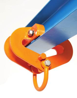
2 IMPORTANT Please read this instruction manual before using these products. This manual contains important information regarding safety, operation, installation & maintenance. ALWAYS operate, inspect and maintain these products in accordance to the relevant Australian Standards AS and AS4991 INTRODUCTION Thank you for purchasing your new Pacific Clamp and / or Trolley. These lifting devices now use the latest technology to ensure you of a higher quality, robust design with a high level of operator safety which is easy and safe to use while ensuring a longer service life. It is important that this instruction manual is kept in a safe place where any operator of the Pacific Clamps and / or Trolleys can refer to it to understand the operating principles of these devices. All users should read this manual in full and understand the safe operating principles of these devices. FEATURES Pacific Self-locking Beam Trolleys Designed and tested in accordance with Australian Standard AS Quick and easy installation with no tools required. Suitable for a wide range of beam sizes. Inclusive of a spring assisted locking pin for safe and easy attachment to the beam. A cost-effective and time saving way of suspending loads. Ideal for the rigging industry. Pacific Adjustable Angle Clamps Designed and tested in accordance with Australian Standard AS4991. Quick and easy installation with no tools required. Suitable for a wide range of angle sections. Inclusive of an adjustable locking pin for safe and easy attachment.
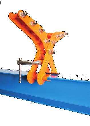
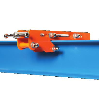
3 FEATURES (CONT.) Features a V-type clamping jaw which secures the clamp to the angle section. A cost-effective and time saving way of suspending loads. This clamp can be used as both an anchor and suspension device. Ideal for the rigging industry. Pacific Top Girder Clamps Designed and tested in accordance with Australian Standard AS4991. Quick and easy installation with no tools required. Suitable for a wide range of beam sizes. Available as a Low Profile Girder Clamp for applications where headroom is restricted. Inclusive of a locking pin with articulated handle for safe and easy fixture. A cost-effective and time saving way of suspending loads. This clamp can be used as both an anchor and suspension device. Ideal for the rigging industry.
4 SPECIFICATIONS Pacific Self-locking Beam Trolleys MODEL CLP250 CLP251 CLP252 Rated Capacity 3 tonne 6 tonne 10 tonne Beam Size (mm) Weight (kg) DIMENSIONS (in mm) Pacific Self-locking Beam Trolleys MODEL CLP250 CLP251 CLP252 A B C D E H J K
5 SPECIFICATIONS (CONT.) Pacific Adjustable Angle Clamps MODEL CLP253 CLP254 CLP255 CLP256 Rated Capacity 500 kg 1 tonne 1.5 tonne 3 tonne Beam Size (mm) Weight (kg) DIMENSIONS (in mm) Pacific Adjustable Angle Clamps MODEL CLP253 CLP254 CLP255 CLP256 A B C D E G H J K
6 SPECIFICATIONS (CONT.) Pacific Top Girder Clamps MODEL CLP257 CLP kg 200 kg Head Room Standard Low Profile Beam Size (mm) Rated Capacity Weight (kg) DIMENSIONS (in mm) Pacific Top Girder Clamp Standard (CLP257) Pacific Top Girder Clamp Low Profile (CLP258) MODEL CLP257 CLP258 A 357 (max) 407 B C D E F - 60
7 SAFETY INSTRUCTIONS Girder Trolleys The following Safety Instructions outline the care and safe use of GIRDER TROLLEYS and are based on Section 7 of the LEEA Code of Practice for the Safe Use of Lifting Equipment. This information is of a general nature; only covering the main points for the safe use of travelling girder trolleys. It may be necessary to supplement this information for specific applications. ALWAYS Store and handle trolleys correctly Inspect trolleys, blocks and accessories before use and before placing into storage Ensure the wheel profile is suitable for the track Check the trolley width is correctly set for the track Ensure the track is fitted with positive end stops Push rather than pull loads suspended on push/pull trolleys NEVER Expose trolleys to chemicals, particularly acids, without consulting the supplier Force or wedge the suspension hook of blocks onto the load bar Throw or drop a trolley Expose a trolley directly to the elements, water spray, steam etc without consulting the supplier Use a trolley with chipped or otherwise damaged wheel flanges Obliquely side load a trolley Storing & Handling Trolleys Users will often remove blocks for storage leaving the trolley in place. They must be suitably protected from damage and corrosion. When removing trolleys for separate storage the following steps should be taken: Never return damaged trolleys to storage. They should be dry, clean and protected from corrosion. Store trolleys in a dry, clean area protected from damage. Operating chains, pendant power controls etc may be removed, clearly labelled and stored separately to avoid damage. Trolleys should not be dropped or thrown down.
8 SAFETY INSTRUCTION (CONT.) Girder Trolleys Installing & Commissioning Follow any specific installation instructions issued by the supplier. These should be read in conjunction with the instructions applicable to the block and should at least pay attention to the following: Check the runway track is level, has an even running surface and is fitted with positive end stops which engage with the trolley frame or wheel treads. Ensure the trolley is set to correct width with spacers (where applicable) equally disposed about the centre line, that the wheel profile is suitable for the track section and anti-tilt devices (where applicable) are correctly set. If the trolley was dismantled for erection ensure the parts are correctly re-assembled. Ensure that all bolts, nuts etc are in place and fully tightened. If end stops were removed ensure they are replaced. Using Trolleys Safely The safe use of the trolley will largely be governed by the requirements for the block with which it is to be used but should take the following matters into account: Do not use defective trolleys, blocks or accessories. The trolley must be placed directly over the centre of gravity of the load. Under no circumstances must they be obliquely side loaded as this will cause them to tip, resulting in damage to the track or the trolley becoming detached from the track and falling. In the case of push/pull trolleys push rather than pull suspended loads taking care to avoid swinging loads. In-service Inspection & Maintenance Maintenance may be combined with that of the block but should ensure that the trolley is clean and that moving parts are regularly lubricated. Keep the running surface of wheels and contact surface of track free of any contamination including lubricants. Regularly inspect the trolley and, in the event of the following defects, refer the trolley to a Competent Person for thorough examination: wear; damage to wheel treads and flanges; insecure wheels and axle pins; loose nuts; distorted side plates, load bar or suspension eyes; damaged or worn hand chain; damaged controls; worn, chipped drive gears; illegible markings. Lifting Equipment Engineers Association 2011 SI No. 16.3
9 SAFETY INSTRUCTIONS (CONT.) Beam Clamps The following Safety Instructions outline the care and safe use of BEAM CLAMPS and are based on Section 8 of the LEEA Code of Practice for the Safe Use of Lifting Equipment. This information is of a general nature; only covering the main points for the safe use of beam clamps intended for use as suspension points for lifting appliances. It may be necessary to supplement this information for specific applications. ALWAYS Store and handle beam clamps correctly Inspect beam clamps and accessories before use and before placing into storage Ensure the supporting structure is adequate for the full load that will be imposed and suitable for the application. Check the clamp is of the correct profile and size, or correctly adjusted, for the beam width and that it seats correctly on the beam flange. Ensure the beam clamp is strong enough for the full load that will be imposed. Check that the clamp is directly over the centre of gravity of the load. NEVER Use beam clamps which are unidentified or uncertified for lifting applications. Never replace bolts, shackles etc without consulting the supplier. Throw or drop beam clamps. Use beam clamps on damaged or distorted beams. Force or wedge hooks of lifting appliances into the attachment eye or fitting (eg shackle). Obliquely load beam clamps without the authority of the supplier. Storing & Handling Beam Clamps Never return damaged beam clamps to storage. They should be dry, clean and protected from corrosion. Where necessary fasteners should be reassembled immediately after removal from the beam. Beam clamps should not be dropped or thrown down.
10 SAFETY INSTRUCTION (CONT.) Beam Clamps Using Beam Clamps Safely The safe use of beam clamps will largely be governed by the requirements for the lifting appliance with which it is to be used but should take the following matters into account: Do not use defective beam clamps, lifting appliances or accessories. Ensure the structure from which the clamp is to be suspended is undamaged and is adequate for the full load that will be imposed. If any doubt exists consult a Competent Person to confirm suitability. Ensure the clamp is suitable for the application, correct size and profile for the beam and seats correctly. It must not cause localised overloading. Ensure the lifting appliance is compatible with the clamp and that hooks or other attachments fit freely into the eye, shackle etc of the clamp. The clamp must be positioned directly over the centre of gravity of the load and the load must not be allowed to swing or impose an oblique loading. If two clamps are to be used in tandem the use of ancillary equipment may also be necessary, eg spreader beam. Care must be taken to ensure no one clamp takes more than its rated capacity. In-service Inspection & Maintenance Beam clamps should be cleaned and any moving parts lubricated at appropriate intervals unless the suppliers specific instructions indicate otherwise. Regularly inspect the beam clamp, in the event of the following defects refer the clamp to a Competent Person for thorough examination: wear, damage or distortion, cracks, insecure bolts etc, corrosion, illegible markings. Lifting Equipment Engineers Association 2011 SI No. 17.3
11 OPERATING INSTRUCTIONS Pacific Self-locking BeamTrolleys Do not exceed the rated capacity of the Pacific Trolley. The Pacific Trolley is NOT suitable for lifting persons under any circumstances. The Trolley must always be installed and used by a competent person. Always check the device for damaged, deformed or missing parts before putting in use. Select an appropriate beam section which has been assessed by a competent person as being safe and capable of supporting the additional load. Disengage the spring assisted locking pin to open the Trolley. Position one side of the Trolley on the beam. Close the opposite side of the Trolley until the locking pin is closed in the engaged position. Attach the lifting equipment to the suspension point. Stand clear while the load is lifted slightly. Visually inspect that the Trolley is attached properly, the load is balanced and is safe to continue the lifting operation. On completion of use, remove the lifting equipment from the suspension point. Disengage the locking pin to unlock and open the Trolley and remove the Trolley from the beam. Pacific Adjustable Angle Clamps Do not exceed the rated capacity of the Pacific Clamp. The Pacific Clamp is NOT suitable for lifting persons under any circumstances. The Clamp must always be installed and used by a competent person. Always check the device for damaged, deformed or missing parts before putting in use. Select an appropriate angle section which has been assessed by a competent person as being safe and capable of supporting the additional load. Release the adjustable locking pin in order to fit the clamp to the angle iron. Slide on the clamp and lock the adjustable locking pin, ensuring the V- type jaw is secure on the outer angle section. Attach the lifting equipment to the suspension point. Stand clear while the load is lifted slightly. Visually inspect that the Clamp is attached properly, the load is balanced and is safe to continue the lifting operation.
12 OPERATING INSTRUCTIONS (CONT.) On completion of use, remove the lifting equipment from the suspension point. Release the adjustable locking pin to unlock and open the Clamp and remove the Clamp from the angle section.. Pacific Top Girder Clamps Do not exceed the rated capacity of the Pacific Clamp. The Pacific Clamp is NOT suitable for lifting persons under any circumstances. The Clamp must always be installed and used by a competent person. Always check the device for damaged, deformed or missing parts before putting in use. Select an appropriate beam section which has been assessed by a competent person as being safe and capable of supporting the additional load. Release the articulated locking pin in order to fit the clamp to top the beam section. Slide on the clamp and lock the articulated locking pin until both jaws are secured to the beam. Always make sure the safety locking nut is closed. Attach the lifting equipment to both suspension points. Stand clear while the load is lifted slightly. Visually inspect that the Clamp is attached properly, the load is balanced and is safe to continue the lifting operation. On completion of use, remove the lifting equipment from the suspension point. Release the articulated locking pin and remove the Clamp from the angle section. MAINTENANCE INSTRUCTIONS The robust and simple design of the Pacific Clamps and Trolleys will provide a long service life with minimal maintenance or repair required. Avoid damage to the screw keep dirt, grit and other contaminants away from the threads and other moving parts while in use. Periodically open the clamp jaws fully and clean any contaminants from the screw threads. Apply a light coating of grease to prevent rust and provide lubrication. Store carefully when not in use. Inspect regularly and remove any damaged clamp from service immediately for examination by a competent person. Contact your local dealer for further assistance.
13 SPARE PARTS FOR PACIFIC SELF-LOCKING BEAM TROLLEYS NO. DESCRIPTION QTY 1 Flat washer 4 2 Spring 1 3 Stay bolt 1 4 Front fixed side plate 1 5 Lock pin 1 6 Rear fixed side plate 1 7 Right side plate assy. 1 8 Lock pin bush 1 9 Self-lock nut 1 10 Running wheel 4 11 Bearing 4 12 Circlip A 4 NO. DESCRIPTION QTY 13 Circlip B 4 14 Nut 4 15 Left side late assy Washer 4 17 Front link plate 1 18 Rear link plate 1 19 Running wheel axle 4 20 Stop plate 4 21 Bush 1 22 Suspension ring 1 23 Hexagon screw bolt 1 24 Handle 1
14 SPARE PARTS FOR PACIFIC ADJUSTABLE ANGLE CLAMPS NO. DESCRIPTION QTY 1 Side Plate 2 2 U-plate 1 3 Socket head cap screw 1 4 Press block 1 5 Screw 1 6 Handle lever 1 7 Die 2 8 Hex-head bolt 1 9 Washer 2 10 Suspension ring 1 11 Nut 1 12 Reinforcing steel 1 13 Metal self-lock nut 1
15 SPARE PARTS FOR PACIFIC TOP GIRDER CLAMPS STANDARD NO. DESCRIPTION QTY 1 Stop block 1 2 Hexagon socket bolt 1 3 Right stay bolt I 1 4 Left stay bolt II 3 5 Left connection bolt 1 6 Side plate 4 7 Flat washer 16 8 Bolt I 3 9 Flat washer 2 10 Hexagon bolt 1 11 Positioned bush 1 12 Plate 2 NO. DESCRIPTION QTY 14 Left stay bolt I 1 15 Hexagon socket bolt 1 16 Spacer block 1 17 Elastic cylinder pin 1 18 Handle part 1 19 Handle lever 1 20 Die 2 21 Lock nut 1 22 Bolt 1 23 Right connection bolt 1 24 Metal self-lock nut 8 25 Metal self-lock nut 1 13 Bolt II 3
16 SPARE PARTS FOR PACIFIC TOP GIRDER CLAMPS LOW PROFILE NO. DESCRIPTION QTY 1 Right stay bolt II 1 2 Right connection bolt 1 3 Hexagon socket screw 1 4 Stop block 1 5 Side plate 4 6 Bolt II 2 7 Right stay bolt I 1 8 Left stay bolt I 1 9 Flat washer 12 NO. DESCRIPTION QTY 11 Bolt I 2 12 Lock nut 1 13 Elastic cylinder pin 1 14 Handle lever 1 15 Die 2 16 Handle part 1 17 Spindle 1 18 Left connection bolt 1 19 Left stay bolt II 1 10 Metal self-lock nut 8
17 WARRANTY All Pacific Trolleys and Clamps are guaranteed against any apparent fault arising from manufacturing defects caused by faulty materials and / or workmanship for a period of five years from the date of the original purchase. Should any part fail due to the above within the specified period, Pacific Hoists Pty Ltd will repair or replace the defective part free of charge provided that the equipment is delivered to Pacific Hoists Pty Ltd. Freight charges both ways are payable by the claimant and no liability is accepted for loss or damage during transit. The claimant is required to produce the original invoice or other purchase documents as proof of purchase. The warranty does not cover the purchaser or any other person for damage, loss, normal wear or faults caused from misuse or incorrect installation of the equipment. The equipment is required to have been installed and operated correctly by qualified personnel and has not been subject to abuse, neglect or adjustment carried out by an unauthorized person. This warranty is in addition to, and in no ways restricts, any of the implied conditions or warranties conferred by Commonwealth, State of Territorial legislation. This warranty may only be varied with the written approval of the Directors of Pacific Hoists Pty Ltd.
18 INSPECTION & SERVICE LOG DATE NOTES SIGNATURE Imported and distributed by Pacific Hoists Pty Ltd via a national distributor network throughout Australia and New Zealand. For further information in relation to this product, please contact the distributor outlet where the product was purchased. HEAD OFFICE 24 Foundry Road Seven Hills NSW 2147 P F E sales@pacifichoists.com.au WESTERN AUSTRALIA Unit 1, 31 Colin Jamieson Drive Welshpool WA 6106 P F E sales@pacifichoists.com.au QUEENSLAND Unit 5, 54 Nealdon Drive Meadowbrook QLD 4131 P F E sales@pacifichoists.com.au NEW ZEALAND 11 Druces Road Manukau City Auckland NZ 2104 P F E sales@pacifichoists.co.nz
BEAM CLAMP INSTRUCTION MANUAL
 BEAM CLAMP INSTRUCTION MANUAL Imported exclusively for the Global Lifting Group by Pacific Hoists Pty. Ltd. & Pacific Hoists Ltd. 2 SAFETY INSTRUCTIONS THE FOLLOWING SAFETY INSTRUCTIONS OUTLINE THE CARE
PLATE CLAMPS INSTRUCTION MANUAL
 PLATE CLAMPS INSTRUCTION MANUAL Imported exclusively by Pacific Hoists Pty. Ltd. & Pacific Hoists Ltd. In support of cancer charities in Australia & New Zealand Universal Plate Clamp 1 Horizontal Plate
ELECTRIC LIFTER TROLLEY INSTRUCTION MANUAL
 ELECTRIC LIFTER TROLLEY INSTRUCTION MANUAL Imported exclusively by Pacific Hoists Pty. Ltd. & Pacific Hoists Ltd. In support of cancer charities in Australia & New Zealand 2 www.jbstools.com WWW.CHALLENGERHOISTS.COM.AU
OPERATIONS MANUAL LEVER CHAIN HOIST
 OPERATIONS MANUAL LEVER CHAIN HOIST IMPORTANT SAFETY INFORMATION Please read, understand and follow all safety information contained in these instructions prior to the use of this hoist. Retain these instructions
AL-KO OFF-ROAD PIN COUPLING USERS MANUAL
 AL-KO OFF-ROAD PIN COUPLING USERS MANUAL Save This Manual. Keep this manual for the assembly, operation, maintenance and cleaning procedures. Keep this manual and the receipt or proof of purchase in a
Operating Instructions. TM Girder Clamps
 Operating Instructions TM Girder Clamps Original operating instructions in keeping with the EC Machinery Directive TM-BC-10 TM-BC-20 TM-BC-30 TM-BC-50 TM girder clamps meet requirements as per EU Machinery
Safelift Overhead Runway Beams & Rolling Beam Cranes
 Operation & Maintenance Instructions Instructions for Safe Use Safelift Overhead Runway Beams & Rolling Beam Cranes Certification Safelift overhead runway beams and rolling beam cranes are lifting appliances
MANUAL LIFTER TROLLEY INSTRUCTION MANUAL
 MANUAL LIFTER TROLLEY INSTRUCTION MANUAL Imported exclusively by Pacific Hoists Pty. Ltd. & Pacific Hoists Ltd. In support of cancer charities in Australia & New Zealand 2 www.jbstools.com WWW.CHALLENGERHOISTS.COM.AU
K877. Fitting Kit. Fitting Instructions for Basic Carrier. x 1 x 1 x 1 x 1. x 2 x 2 x 1 x 1. x 1 x 1. Revision No: 3C 1
 Fitting Instructions for Basic Carrier x 1 x 1 x 1 x 1 x 2 x 2 x 1 x 1 x 1 x 1 Revision No: 3C 1 MAX kgs (lbs) W/P WHD Subaru Impreza, 4dr Sedan 12-+ NZ 75 kgs (165 lbs) 75 kgs (165 lbs) Impreza, 4dr Sedan
Manpower MANUAL HOISTS. Manual hoists that take the weight out of heavy duty lifting. The lifting equipment specialists
 Manpower Manual hoists that take the weight out of heavy duty lifting The lifting equipment specialists MANUAL HOISTS PWB Anchor Manual Hoists The every-site solution to lifting & lowering PWB Anchor s
K681. Fitting Kit. Fitting Instructions for Basic Carrier. x 4 x 2 x 2 x 2. x 2. Revision No: 4D 1
 Fitting Kit Fitting Instructions for Basic Carrier x 4 x 2 x 2 x 2 x 2 Revision No: 4D 1 MAX kgs (lbs) W/P WHD Mitsubishi Mirage Space Star, 5dr Hatch 13-15 CN 75 kgs (165 lbs) 75 kgs (165 lbs) Mirage,
AL-KO OFF-ROAD BALL COUPLING USERS MANUAL
 AL-KO OFF-ROAD BALL COUPLING USERS MANUAL Save This Manual. Keep this manual for the assembly, operation, maintenance and cleaning procedures. Keep this manual and the receipt or proof of purchase in a
K708. Fitting Kit. Fitting Instructions for Basic Carrier. x 2 x 2 x 4 x 4. x 4. Revision No: 1A 1
 Fitting Kit Fitting Instructions for Basic Carrier x 2 x 2 x 4 x 4 x 4 Revision No: 1A 1 MAX kgs (lbs) W/P WHD Skoda Octavia III, 5dr Liftback 09-12 NZ 35 kgs (77 lbs) 35 kgs (77 lbs) Octavia, 5dr Hatch
K381W. Fitting Kit. Fitting Instructions for Basic Carrier. x 2 x 2 x 2 x 2. x 4. Revision No: 4C 1
 Fitting Kit Fitting Instructions for Basic Carrier x 2 x 2 x 2 x 2 x 4 Revision No: 4C 1 MAX kgs (lbs) W/P WHD Skoda Octavia II, 4dr Liftback 04-09 NZ 75 kgs (165 lbs) 75 kgs (165 lbs) Octavia II, 4dr
Q20. Track System. Fitting Instructions for Basic Carrier. x 2 x 2 x 2 x 1. x 1 x 1 x 4 x 4. Revision No: 1A 1
 Track System Fitting Instructions for Basic Carrier x 2 x 2 x 2 x 1 x 1 x 1 x 4 x 4 Revision No: 1A 1 x 4 x 1 x 20 x 20 x 20 2 First Time Installation Remove parts from inside the package and check. Contact
K309. Fitting Kit. Fitting Instructions for Basic Carrier. x 1 x 2 x 2 x 4. x 1 x 2 x 1. Revision No: 7C 1
 Fitting Instructions for Basic Carrier x 1 x 2 x 2 x 4 x 1 x 2 x 1 Revision No: 7C 1 MAX kgs (lbs) W/P WHD Toyota Emina Lucida, 4dr MPV 92-99 EU 75 kgs (165 lbs) 75 kgs (165 lbs) Emina Lucida, 4dr MPV
K683. Fitting Kit. Fitting Instructions for Basic Carrier. x 4 x 4 x 8 x 2. x 2 x 4 x 4 x 4. x 4. Revision No: 3C 1
 Fitting Kit Fitting Instructions for Basic Carrier x 4 x 4 x 8 x 2 x 2 x 4 x 4 x 4 x 4 Revision No: 3C 1 MAX kgs (lbs) W/P WHD Mitsubishi Outlander GX3, 5dr SUV 13-15 CN 75 kgs (165 lbs) 75 kgs (165 lbs)
K163. Fitting Kit. Fitting Instructions for Basic Carrier. x 4. Revision No: 2C 1
 Fitting Kit Fitting Instructions for Basic Carrier x 4 Revision No: 2C 1 Nissan MAX kgs (lbs) W/P WHD Elgrande, 4dr MPV 97-02 NZ 50 kgs (110 lbs) 50 kgs (110 lbs) Elgrande, 4dr MPV 97-02 AU 50 kgs (110
Before equipment use, please read this operation manual carefully. Serial Number: Date Purchased:
 Pushed & Geared Trolleys OPERATION MANUAL This operation manual is intended as an instruction manual for trained personnel who are in charge of installation, maintenance, repair etc. Before equipment use,
K131. Fitting Kit. Fitting Instructions for Basic Carrier. x 1 x 4 x 4 x 2. x 2 x 4. Revision No: 2C 1
 Fitting Instructions for Basic Carrier x 1 x 4 x 4 x 2 x 2 x 4 Revision No: 2C 1 MAX kgs (lbs) W/P WHD Toyota Estima, 5dr MPV 00-Apr 06 NZ 50 kgs (110 lbs) 50 kgs (110 lbs) Estima, 5dr MPV 00-Apr 06 NZ
K682. Fitting Kit. Fitting Instructions for Basic Carrier. x 4 x 4 x 4 x 8. x 4 x 2 x 2 x 4. x 4 x 4 x 4. Revision No: 1A 1
 Fitting Instructions for Basic Carrier x 4 x 4 x 4 x 8 x 4 x 2 x 2 x 4 x 4 x 4 x 4 Revision No: 1A 1 MAX kgs (lbs) W/P WHD Holden Colorado 7, 5dr SUV 13-+ NZ 75 kgs (165 lbs) 100 kgs (220 lbs) Colorado
Rev. 10/27/2015 CDL-2000, MANUAL
 VESTIL MANUFACTURING CORP. 2999 North Wayne Street, P.O. Box 507, Angola, IN 46703 Telephone: (260) 665-7586 Toll Free (800) 348-0868 Fax: (260) 665-1339 www.vestilmfg.com e-mail: sales@vestil.com CDL-2000
K440. Fitting Kit. Fitting Instructions for Basic Carrier. x 4 x 4 x 4 x 4. x 1 x 1 x 4 x 1. Revision No: 10J 1
 Fitting Kit Fitting Instructions for Basic Carrier x 4 x 4 x 4 x 4 x 1 x 1 x 4 x 1 Revision No: 10J 1 MAX kgs (lbs) W/P WHD Volkswagen Caddy Maxi, 5dr Van 08-14 ZA 75 kgs (165 lbs) 100 kgs (220 lbs) Caddy
STRUT SPRING COMPRESSOR
 OWNER S MANUAL PRODUCT CODE: 1221T STRUT SPRING COMPRESSOR Capacity Stroke Spring Coil Spring Spring Coil Net Weight (Maximum) Thickness Length Diameter 1,000kg 330mm 10-18mm 210-570mm 100-158mm 36kg Made
BELOW-THE-HOOK & MATERIAL HANDLING EQUIPMENT
 BELOW-THE-HOOK & MATERIAL HANDLING EQUIPMENT lifting EQUIPMENT Tongs HBTF Bar Tong Fixed... Page 62 TONGS HBTA Bar Tong Adjustable... Page 63 lifting EQUIPMENT HBTF BAR TONG FIXED FEATURES This style of
K1013 K1013. Fitting Instructions for Basic Carrier. x 4 x 4 x 1 x 8. x 4 x 1 x 4 x 1. x 4 x 1 x 1 x 2. Revision No: 1A 1
 Fitting Instructions for Basic Carrier x 4 x 4 x 1 x 8 x 4 x 1 x 4 x 1 x 4 x 1 x 1 x 2 Revision No: 1A 1 MAX kgs (lbs) W/P WHD Holden Spark, 5dr Hatch 16-+ AU 50 kgs (110 lbs) 50 kgs (110 lbs) Spark, 5dr
E17M ROLLING STOCK BRAKES
 E17M ROLLING STOCK BRAKES PURPOSE AND SCOPE The purpose of this Procedure is to advise Laing O Rourke personnel of the braking standards to be applied and to ensure those people involved in maintaining
Lincoln Hoist. Web Hoist Operating Manual. Lincoln Hoist
 Lincoln Hoist Web Hoist Operating Manual Lincoln Hoist Mfg. by Lincoln Precision Machining Company 121 Creeper Hill Road, P.O. Box 458, North Grafton, MA 01536 USA Toll Free (888) 306-7222 Phone (774)
Safe-T-Glide Installation Instructions
 Safe-T-Glide Installation Instructions Finger Safe-T-Glide Panel Door Mechanism Finger Safe-T-Glide Panel Door Step 1 Stand door panel upright central to garage door opening and ensure it is level by placing
Mighty Mack Wheeled Walker
 Mighty Mack Wheeled Walker Handle with lever brake Backrest Handle height adjustment knob Brake cable Extra wide padded seat Shopping basket Side brace 7 inch (180 mm) wheels user guide Prior to use please
K500. Fitting Kit. Fitting Instructions for Basic Carrier. x 1 x 4 x 4 x 4. Revision No: 14N 1
 Fitting Kit Fitting Instructions for Basic Carrier x 1 x 4 x 4 x 4 Revision No: 14N 1 MAX kgs (lbs) W/P WHD Mazda 5, 5dr MPV 06-10 EU 75 kgs (165 lbs) 75 kgs (165 lbs) 5, 5dr MPV 06-10 US 75 kgs (165 lbs)
Wallace Tri-Adjustable Gantry Cranes Square Tube Assembly Instructions
 Wallace Tri-Adjustable Gantry Cranes Square Tube Assembly Instructions For any additional information, Please call 1- S 1. Read and understand instructions before using this gantry. 2. Inspect gantry thoroughly
Package Contents Part A (3) I-Beam (1) Base (2) Other parts
 I-Beam (1) Base (2) Other parts") Page 1 Installation Instructions for 81245 Adjustable Height Gantry Crane 1-Ton Capacity Table of Contents Important Safety Information pg. 2 Specific Operation Warnings pg. 2 Main Parts of Product pg.
Page 1 Installation Instructions for 81245 Adjustable Height Gantry Crane 1-Ton Capacity Table of Contents Important Safety Information pg. 2 Specific Operation Warnings pg. 2 Main Parts of Product pg.
BELOW-THE-HOOK & MATERIAL HANDLING EQUIPMENT
 BELOW-THE-HOOK & MATERIAL HANDLING EQUIPMENT lifting EQUIPMENT HRLB ROLL LIFTING BEAM...Page 44 HMRL MOTORIZED ROLL LIFTER...Page 45 HRGT ROLL GRIPPING TONGS...Page 46 HRLCH ROLL LIFTING C-HOOK...Page
Fitting Instruction for EZI-GRIP Bike Rack
 Fitting Instruction for EZI-GRIP Bike Rack Congratulations on purchasing Ezi-Grip to carry your valued bicycles. We are sure you will get many years of enjoyable use from your Ezi-Grip Bike Rack. These
CHESTER HOIST AIR LOW HEADROOM CHAIN HOISTS AL-680 SECTION A
 CHESTER HOIST AIR LOW HEADROOM CHAIN HOISTS AL-680 SECTION A OPERATING and MAINTENANCE INSTRUCTIONS FOR AL SERIES HOISTS Users should refer to the ANSI B30.16 American National Standard and ASME HST-5M
OPERATION & MAINTENANCE INSTRUCTIONS
 10 TONNE HEAVY DUTY LONG CHASSIS TROLLEY JACK MODEL NO: CTJ10GLS PART NO: 7623095 OPERATION & MAINTENANCE INSTRUCTIONS LS0915 INTRODUCTION Thank you for purchasing this CLARKE 10 Tonne Heavy Duty Long
500kg TELESCOPIC TRANSMISSION LIFTER
 Product Code: 2056T PRODUCT CODE: 2056T 500kg TELESCOPIC TRANSMISSION LIFTER Safe Working Capacity 500kg Base Dimension 540 x 570 mm Minimum Height 1175mm Maximum Height 1900mm Made in China to TQB Brands
AL-KO ESC USER MANUAL
 Vehicle Technology QUALITY FOR LIFE AL-KO ESC USER MANUAL OPERATING INSTRUCTIONS WARRANTY DETAIL About AL-KO ESC The new AL-KO ESC (Electronic Stability Control) is a sway and swerve stability control
Provided by: Operating, Maintenance & Parts Manual
 Provided by: www.hoistsdirect.com TB681.qxd 11/29/2004 3:04 PM Page 1 Operating, Maintenance & Parts Manual TB603 Manually Lever Operated Chain Hoist 1100 POUNDS MAXIMUM CAPACITY (500 kg) Follow all instructions
Capacity (tonnes) 0.25t. No. of Falls 1. Load Chain (mm) Load Chain Grade 80
 0.25t. No. of Falls 1. Load Chain (mm) Load Chain Grade 80") Capacity (tonnes) Model NO. 0.25t K025 No. of Falls Load Chain (mm) 4 2 Load Chain Grade 80 Pull To Lift Rated Load (N) Test load (tonnes) Hand Chain (mm) Std. lift (ft) Net. Weight (lbs) Gross. Weight
Capacity (tonnes) Model NO. 0.25t K025 No. of Falls Load Chain (mm) 4 2 Load Chain Grade 80 Pull To Lift Rated Load (N) Test load (tonnes) Hand Chain (mm) Std. lift (ft) Net. Weight (lbs) Gross. Weight
Translation of the Original operating instructions Lifting device Z 70 /...
 Translation of the Original operating instructions Lifting device Z 70 /... Content 1. Lifting device / Correct use according to regulations 2. Basic principles 3. General information 4. Special remarks
OWNER S MANUAL PRODUCT CODE: 2006T
 Jul-18 Product Code: 2006T OWNER S MANUAL PRODUCT CODE: 2006T HYDRAULIC PIPE BENDER 12,000KG Model Capacity Bending Die No of Attachments 12,000kg 1/2", 3/4", 1", 1-1/4", 1-1/2", 2" 6 Made in China to
Trolleys and beam clamps
 32 Trolleys and beam clamps Trolleys and beam clamps Yale trolleys and beam clamps can be supplied in many different designs and are used to support and mount hoisting equipment for fixed or traversing
Tri-Wheel Wheeled Walker
 Tri-Wheel Wheeled Walker Handle with lever brake Brake cable Handle height adjustment knob Removable basket and tray Large vinyl bag 8 inch (203 mm) wheels user guide Prior to use please read all instructions.
SHOP RIGGING & OVERHEAD HOIST SAFETY PROGRAM
 Purpose & Scope CLIMATE ENGINEERS, INC. (CE) is dedicated to the protection of our employees from occupational injuries and illnesses. The purpose of this program is to provide procedures to be followed
STANDARD SHAPES TROLLEY PARTS MANUAL
 STANDARD SHAPES TROLLEY PARTS MANUAL, Unified Industries, Inc. All Rights Reserved. www.unified-ind.com PARTS AND REPAIR MANUAL This manual has been compiled to expedite the ordering of repair parts for
K450. Fitting Kit. Fitting Instructions for Basic Carrier. x 1 x 8 x 8 x 4. x 4 x 4 x 1 x 4. Revision No: 12L 1
 Fitting Kit Fitting Instructions for Basic Carrier x 1 x 8 x 8 x 4 x 4 x 4 x 1 x 4 Revision No: 12L 1 MAX kgs (lbs) W/P WHD Toyota 4 Runner, 5dr SUV 96-02 US 75 kgs (165 lbs) 75 kgs (165 lbs) 4 Runner,
ATV TRACK KIT. Operator s Manual Installation Instructions Service Instructions Replacement Parts List. Effective Date: October, 2012
 p/n 2258-642 ATV TRACK KIT Operator s Manual Installation Instructions Service Instructions Replacement Parts List Track Assembly Kits (p/n 1436-204) Mounting Assembly Kits (p/n 1436-205) 1436-815) Effective
Fitting Kit K987. EN Fitting Instructions for Basic Carrier CAUTION: Professional installation recommended. x 4 x 4 x 4 x 8. x 4 x 4 x 4 x 1.
 Fitting Kit Fitting Instructions for Basic Carrier CAUTION: Professional installation recommended x 4 x 4 x 4 x 8 x 4 x 4 x 4 x 1 x 1 Revision No: 1A 1 MAX kgs (lbs) W/P WHD Tata Xenon Double Cab, 4dr
K1022. Fitting Kit. Fitting Instructions for Basic Carrier. x 4 x 4 x 8 x 1. x 4 x 4 x 1 x 4. x 8 x 4. Revision No: 2B 1
 Fitting Kit Fitting Instructions for Basic Carrier x 4 x 4 x 8 x 1 x 4 x 4 x 1 x 4 x 8 x 4 Revision No: 2B 1 MAX kgs (lbs) W/P WHD Mercedes-Benz Sprinter Cab Chassis, 2dr Van 07-+ AU 50 kgs (110 lbs) 50
Letron Auto Gates (Australia) Pty. Ltd. User s Installation Manual
 Pty. Ltd. User s Installation Manual") Letron Auto Gates (Australia) Pty. Ltd. User s Installation Manual Sliding Gate Motor AUTOMATIC OBSTRUCT PHOTO ELECTRIC BEAM ROLLING CODE SYSTEM AUTO CLOSE DOOR SOLAR COMPATIBLE ( DC ONLY ) Model SL810
Letron Auto Gates (Australia) Pty. Ltd. User s Installation Manual Sliding Gate Motor AUTOMATIC OBSTRUCT PHOTO ELECTRIC BEAM ROLLING CODE SYSTEM AUTO CLOSE DOOR SOLAR COMPATIBLE ( DC ONLY ) Model SL810
MG12K24T60V4 Mechanical Grapple
 170 State Route 271 Attachment Solutions MG12K24T60V4 Mechanical Grapple Operators Manual KENCO Mechanical Grapple Operation Manual 1 TABLE OF CONTENTS 170 State Route 271 Section I. General Information....
OVAL GEAR FLOWMETER MECHANICAL MODEL 012 (½ )
") 012 Mech 07.11 OVAL GEAR FLOWMETER MECHANICAL MODEL 012 (½ ) INSTRUCTION MANUAL To the Owner PLEASE READ THIS SAFTEY INFORMATION CAREFULLY BEFORE USE. Read and retain this instruction manual to assist
012 Mech 07.11 OVAL GEAR FLOWMETER MECHANICAL MODEL 012 (½ ) INSTRUCTION MANUAL To the Owner PLEASE READ THIS SAFTEY INFORMATION CAREFULLY BEFORE USE. Read and retain this instruction manual to assist
HEAVY DUTY CRANE HDC RANGE OPERATING G & MAINTENANCE INSTRUCTIONS
 HEAVY DUTY CRANE HDC RANGE OPERATING G & MAINTENANCE INSTRUCTIONS 0599 SPECIFICATIONS cont... No. Description Part No. No. Description Part No. MAXIMUM SAFE WORKING LOADS (kg) HDC50 HDC100 HDC150 HDC200
K435. Fitting Kit. Fitting Instructions for Basic Carrier. x 4 x 4 x 4 x 4. x 4. Revision No: 6F 1
 Fitting Kit Fitting Instructions for Basic Carrier x 4 x 4 x 4 x 4 x 4 Revision No: 6F 1 MAX kgs (lbs) W/P WHD Holden Astra TS, 5dr Hatch Dec 98-Oct 04 AU 75 kgs (165 lbs) 75 kgs (165 lbs) Astra, 5dr Hatch
K327. Fitting Kit. Fitting Instructions for Basic Carrier. x 4 x 4 x 4 x 4. Revision No: 5E 1
 Fitting Kit Fitting Instructions for Basic Carrier x 4 x 4 x 4 x 4 Revision No: 5E 1 Items you will require: Attention: First Time Installation Tape measure Pen Flat-head screwdriver Craft knife Side cutters
Product Parts Information
 Product Parts Information Plain, Hand Chain (Geared) and Air Powered Trolleys Models TR2U015 TR2U030 TRU060 TRU120 TRU125 TRU250 (Dwg. MHP2671) Save These Instructions Form MHD56290 Edition 3 June 2006
DISTRIBUTED BY TULSA CHAIN.COM, LLC.
 OPERATOR S MANUAL BEAM CLAMP 1 TON THROUGH 10 TON These Beam Clamps meet or exceed the following standards: CE AS4991 ANSI B30.10 (For use with manual or powered hoists) pg.1 P.O. Box 845, Winona, MN 55987
MANUAL HOISTING TAKE THE WEIGHT OUT OF HEAVY DUTY LIFTING
 MANUAL HOISTING TAKE THE WEIGHT OUT OF HEAVY DUTY LIFTING CARE & SAFETY INSTRUCTIONS 114 CX & M3 SERIES CHAIN BLOCKS 115-117 C SERIES CHAIN BLOCKS 118 MINI II CHAIN BLOCKS 118 LX & L5 SERIES CHAIN BLOCKS
Roller Door Operator
 INSTALLATION INSTRUCTIONS AND OWNERS MANUAL Roller Door Operator IMPORTANT PLEASE READ THESE INSTRUCTIONS CAREFULLY PRIOR TO COMMENCING THE INSTALLATION OF THE OPERATOR UNIT CAUTION This Automatic Opener
User Manual. T29870 Beam Clamp. Original Instructions. Rev /08//14.
 User Manual T29870 Beam Clamp Original Instructions Rev 1.0-12/08//14 www.doughty-engineering.co.uk Contents Introduction... 2 Exclusion of Liability... 2 Safety Instructions... 2 Operation... 3 Maintenance...
Lineman s Hoist. Operating, Maintenance & Parts Manual. Follow all instructions and warnings for LMST680-2
 Lineman s Hoist LMST0- Operating, Maintenance & Parts Manual Lineman s Hoist Follow all instructions and warnings for inspecting, maintaining and operating this hoist. The use of any hoist presents some
HEAVY DUTY TROLLEY JACK. Operation Manual
 HEAVY DUTY TROLLEY JACK 4T Operation Manual Make sure to read and fully understand the instruction manual before using this product and keep the manual properly 1 General Description Product Description
EXTRA WIDE STEEL ROLLATOR
 EXTRA WIDE STEEL ROLLATOR Product Codes: LM3882WBL Blue LM3882WBU Burgundy Extra Wide steel Rollator liquid coated painted frame. Soft touch hand brakes with locking mechanism. PVC extra wide seat. 8"
Reliance Industries, LLC. Installation, Operation, Inspection and Maintenance Instructions for the Slider Traveling Beam Anchor Clamp
 Reliance Industries, LLC Installation, Operation, Inspection and Maintenance Instructions for the Slider Traveling Beam Anchor Clamp Model # 3096 Model # 3097 Model # 3104 Reliance Industries, LLC PO Box
ROOF BOX INSTRUCTIONS Fitting instructions for Roof Box (EXP1/EXP2)
") ROOF BOX INSTRUCTIONS Fitting instructions for Roof Box (EXP1/EXP2) Items you may require that are not included: Tape measure Step ladder (for taller vehicles) Drill with 7mm drill bit Pack should contain:
ROOF BOX INSTRUCTIONS Fitting instructions for Roof Box (EXP1/EXP2) Items you may require that are not included: Tape measure Step ladder (for taller vehicles) Drill with 7mm drill bit Pack should contain:
500kg HYDRAULIC TABLE LIFT
 Product Code: 6007T OWNER S MANUAL PRODUCT CODE: 6007T 500kg HYDRAULIC TABLE LIFT Working Load Limit 500kg Maximum Height 1575mm Minimum Height 440mm Table Dimensions 1010x520mm Wheel Diameter 150mm Made
46761-E OPERATING, MAINTENANCE & PARTS MANUAL SUPPLEMENT ARMY TYPE TROLLEY HOIST
 OPERATING, MAINTENANCE & PARTS MANUAL SUPPLEMENT ARMY TYPE TROLLEY HOIST Distributed by Tri-State Equipment Company Inc. Email: sales@tsoverheadcrane.com Web: www.tsoverheadcrane.com PH: 3-69-700 FAX:
Lifting Points Rotating Ball-bearing De-centered Weldable Screw-on
 ifting Points Rotating Ball-bearing De-centered Weldable Screw-on ifting Points ifting Points Information 3:2 Rotating Eye ifting Point - REP 3:4 Rotating ifting Point - RP 3:5 Decentered ifting Point
RF6 / RF10 / RF18 Installation Instructions
 RF6 / RF10 / RF18 Installation Instructions Thank you very much for purchasing PIAA product. Read this instruction manual thoroughly for proper use of the product. After completing your installation, please
Installation and Parts Manual for SPANCO A Series Steel Gantry Cranes
 Manual No. 103-0002 08/14 Installation and Parts Manual for SPANCO A Series Steel Gantry Cranes ISO 9001 REGISTERED 2 TABLE OF CONTENTS Warnings... 3 Assembly and Operation...4 Track Installation Instructions...6
Euro Lightweight Wheeled Walker
 Euro Lightweight Wheeled Walker Handle with lever brake Backrest Brake cable Handle height adjustment button Removable shopping bag 8 inch (200 mm) wheels Cane holder user guide Prior to use please read
OPERATION SERVICE PARTS TUGIT2. Manually Operated Short Handle Lever Hoist A3140-XXX
 OPERATION SERVICE PARTS TUGIT2 Manually Operated Short Handle Lever Hoist A3140-XXX Sold & Serviced by Morgan Aero 1450 80 th Street SW Everett WA U.S.A. 425/438.9600 SAFETY PRECAUTIONS WARNING! Improper
1/2-TON MANUAL CHAIN HOIST
 1/2-TON MANUAL CHAIN HOIST Owner s Manual WARNING: Read carefully and understand all ASSEMBLY AND OPERATION INSTRUCTIONS before operating. Failure to follow the safety rules and other basic safety precautions
John Berends Implements Pty Ltd OPERATOR S MANUAL PARTS LIST
 John Berends Implements Pty Ltd AGRICULTURAL ENGINEERS OPERATOR S MANUAL PARTS LIST PRODUCT NO. Lifting Jibs 0140 Lifting Jib 0142 Lifting Jib - Heavy Duty 130 FRANKSTON RD, DANDENONG, VIC. 3175 AUSTRALIA
Miller Compact Manual Quick Couplers
 Miller: Issue 2 Miller Compact Manual Quick Couplers For Mini Excavators (1 to 10 tonne) and Backhoe Loaders Installation Guide and Operator s Instructions IMPORTANT Keep this manual with the machine at
Operator s Manual. Nitro 1000 Nitro 1000X. Nitro 750 Nitro 750X. September REV0
 Operator s Manual Nitro 750 Nitro 750X Nitro 1000 Nitro 1000X September.27.2018REV0 Table of Contents Introduction...3 Safety.....4 Equipment Requirements......5 What You Have Received. 5 Serial Number...6
HYDRAULIC PALLET TRUCK MODEL NO: PT540M/BM/CM & PT685BM/CM PART NO: , , , ,
 HYDRAULIC PALLET TRUCK MODEL NO: PT540M/BM/CM & PT685BM/CM PART NO: 7631700, 7631705, 7631710, 7631715, 7631720 OPERATION & MAINTENANCE INSTRUCTIONS LS0316 INTRODUCTION Thank you for purchasing this CLARKE
ABSOLUTE EQUIPMENT PTY LTD
 Manual Hydraulic Toe Jack Model DTJ Series ABSOLUTE EQUIPMENT PTY LTD 2/186 Granite Street, GEEBUNG QLD 4034 Australia sales@absoluteequipment.com.au Phone: +61 7 3865 4006 Fax: +61 7 3102 6288 This is
OPERATOR S MANUAL GEARED BEAM TROLLEY 1 TON THROUGH 30 TON QUICK ADJUST TROLLEY 1 TON THROUGH 10 TON
 OPERATOR S MANUAL PUSH BEAM TROLLEY 0.5 TON THROUGH 10 TON GEARED BEAM TROLLEY 1 TON THROUGH 30 TON QUICK ADJUST TROLLEY 1 TON THROUGH 10 TON These products meet or exceed the following standards: CE AS1418.2
Crane Forks. Introduction. Important Notes. Key Benefits. User Guide
 User Guide Crane Forks Introduction Fully self levelling, even when unloaded, Conquip Crane Forks have been designed to lift packs of bricks and pallets. The crane attachment has adjustable forks and a
User Guide Rail Scooter
 User Guide Rail Scooter Permaquip Ltd Brierley Industrial Park, Stanton Hill, Sutton-In-Ashfield, Nottinghamshire, NG17 3JZ Tel: +44 (0) 1623 513349 Fax: +44 (0) 1623 517742 E-mail: sales@permaquip.co.uk
In This Document MODULE DESCRIPTION This module provides information on the safety concerns and
 Crane Safety Fact Sheet In This Document MODULE DESCRIPTION This module provides information on the safety concerns and Introduction necessary precautions you will need to be aware of when working Crane
1000-LB. MOTORCYCLE LIFT TABLE OWNER S MANUAL
 1000-LB. MOTORCYCLE LIFT TABLE OWNER S MANUAL WARNING: Read carefully and understand all ASSEMBLY AND OPERATION INSTRUCTIONS before operating. Failure to follow the safety rules and other basic safety
ABSOLUTE EQUIPMENT PTY LTD
 Manual Hydraulic Toe Jack Model DTJ Series ABSOLUTE EQUIPMENT PTY LTD 2/186 Granite Street, GEEBUNG QLD 4034 Australia sales@absoluteequipment.com.au Phone: +61 7 3865 4006 Fax: +61 7 3102 6288 This is
JIB-FM Series Floor Mounted Jib Cranes Instruction Manual
 VESTIL MANUFACTURING CORP. 2999 North Wayne Street, P.O. Box 507, Angola, IN 46703 Telephone: (260) 665-7586 -or- Toll Free (800) 348-0868 Fax: (260) 665-1339 www.vestilmfg.com e-mail: HUsales@vestil.comU
2000 lb Adjustable Gantry Crane
 2000 lb Adjustable Gantry Crane Owner s Manual WARNING: Read carefully and understand all ASSEMBLY AND OPERATION INSTRUCTIONS before operating. Failure to follow the safety rules and other basic safety
3 Axles and brakes. 3.1 Function and construction of the axles Construction Function
 3 Axles and brakes 3.1 Function and construction of the axles 3.1.1 Function Each wheel has an independent suspension system in the axle body (1), so that individual wheel suspension is provided. The swinging
Instructions for: FOLDING ENGINE CRANE PREMIER 2 TONNE. MODEL No: SPC2000
 Instructions for: FOLDING ENGINE CRANE PREMIER 2 TONNE MODEL No: SPC2000 Thank you for purchasing a Sealey product. Manufactured to a high standard, this product will, if used according to these instructions,
Air Curtain. Installation, Operating and Maintenance Instructions
 Installation, Operating and Maintenance Instructions Save this manual for future reference. Air Curtain Model Numbers: ES026, ES036, ES042, ES048, ES060, ES072 READ THIS OWNER S MANUAL CAREFULLY BEFORE
TOOL BOX TALK - SAFE USE OF LIFTING EQUIPMENT
 TOOL BOX TALK - SAFE USE OF LIFTING EQUIPMENT Golden Rule 6 Mechanical Lifting Do not operate any lifting equipment unless It has been approved for use The lift has been assessed by a competent person
SBRL-SERIES SPREADER BEAMS INSTRUCTION MANUAL
 VESTIL MANUFACTURING CORP. 2999 North Wayne Street, P.O. Box 507, Angola, IN 46703 Telephone: (260) 665-7586 -or- Toll Free (800) 348-0868 Fax: (260) 665-1339 www.vestilmfg.com e-mail: info@vestil.com
1000 lb. Adjustable Gantry Crane
 1000 lb. Adjustable Gantry Crane Owner s Manual WARNING: Read carefully and understand all ASSEMBLY AND OPERATION INSTRUCTIONS before operating. Failure to follow the safety rules and other basic safety
Crane Forks. Introduction. Important Notes. Key Benefits. User Guide
 User Guide Crane Forks Introduction Fully self levelling, even when unloaded, Conquip Crane Forks have been designed to lift packs of bricks and pallets. The crane attachment has adjustable forks and a
15,000kg HYDRAULIC BOTTLE JACK
 Product Code: 2013 OWNER S MANUAL PRODUCT CODE: 2013 15,000kg HYDRAULIC BOTTLE JACK Lifting Capacity 15,000kg Max. Lifting Height 447mm Min. Lifting Height 227mm Hydraulic Lift 125mm Screw Adjustment 70mm
3 Ton Trolley Jack. Please read and fully understand the instructions in this manual before operation. Keep this manual safe for future reference.
 Please dispose of packaging for the product in a responsible manner. It is suitable for recycling. Help to protect the environment, take the packaging to the local amenity tip and place into the appropriate
Installation and Maintenance Manual for SPANCO A Series Aluminum Gantry Cranes
 Manual No. 103-0008 REV. 6/11 Installation and Maintenance Manual for SPANCO A Series Aluminum Gantry Cranes ISO 9001 REGISTERED SPANCO, Inc. 2 TABLE OF CONTENTS Warnings... 3 Installation... 4 Maintenance...
WARNING. Electric Recovery Winch. General Safety Precautions
 1 Electric Recovery Winch Thanks for purchasing a WINCH. This manual covers operation and maintenance of the winch. All information in this publication is based on the latest production information available
Traditional Rotary 42 Hoist. Owner s Manual
 Traditional Rotary 42 Hoist Owner s Manual Introduction Congratulations Congratulations on the purchase of your new Hills Traditional Rotary Hoist, which will bring you many years of trouble free and efficient