Collegiate Design Series Suspension 101. Steve Lyman Formula SAE Lead Design Judge DaimlerChrysler Corporation
|
|
|
- Randall Maxwell
- 5 years ago
- Views:
Transcription
1 Collegiate Design Series Suspension 101 Steve Lyman Formula SAE Lead Design Judge DaimlerChrysler Corporation
2 There Are Many Solutions It depends. Everything is a compromise.
3 Suspension 101 Ride Frequency/ Balance (Flat Ride) Motion Ratios Ride Friction Suspension Geometry Selection Suspension Layouts- Double A Arm Variations and Compromises Dampers- A Really Quick Look
4 The thing we had missed was that the excitation at front and rear did not occur simultaneously. The actual case was more like this-- Front Rear Suspension Travel Time Lag Time --with the angle of crossing of the two wave lines representing the severity of the pitch. (From Chassis Design: Principles and Analysis, M illiken & M illiken, SAE 2002)
5 By arranging the suspension with the lower frequency in front (by 20% to start) this motion could be changed to-- Front Suspension Rear Suspension Pitch Suspension Travel Pitch (deg) Time -2 --a much closer approach to a flat ride. (From Chassis Design: Principles and Analysis, M illiken & M illiken, SAE 2002)
6 What ride frequencies are common today? Front Suspension Rear Suspension Ride Rate Corner Unsprung Sprung Ride Rate Corner Unsprung Sprung Ride Frequency Frequency Vehicle wlo tire Weight Weight Weight wlo tire Weight Weight Weight Ratio (Ib/in) (lb) (Ib) (lb) (hertz) (Ib/ in) (lb) (Ib) (lb) (hertz) Rr/ Frt 99 Volvo V70 XC MB E320 4-Matic Jeep KJ Liberty NS Chrysler T&C Pacifica MB E320 4-Matic Peugeot 306 GTI Audi A 6 Quattro MB E320 2WD NA 95 BMW M VW Passa t Neon JR LH Dodge Intrepid Jeep WG Grand Cherokee VW Golf
7 Does motion ratio affect forces transmitted into the body? Motion ratio is spring travel divided by wheel travel. The force transmitted to the body is reduced if the motion ratio is increased.

8 Does motion ratio affect forces transmitted to the body? Wheel Rate: 150 lb/in T L Motion Ratio: 0.5 Not good Force at wheel for 1 wheel travel = 150 lb Spring deflection for 1 wheel travel=0.5 Force at spring for 1 wheel travel = 300 lb Force at body = Force at wheel / MR Spring Rate=300 lb / 0.5 = 600 lb/in Spring Rate= Wheel Rate / MR 2
9 How does ride friction affect frequency? (3.16 Hz) Small inputs don t break through the friction, resulting in artificially high ride frequency (1.05 Hz) (From Chassis Design: Principles and Analysis, Milliken & Milliken, SAE 2002)
10 Ride Summary Flat Ride Improves handling, acceleration, braking performance Plenty of suspension travel Allows lower spring rates & ride frequencies Allows progressive jounce bumper engagement Good motion ratio Reduces loads into vehicle structure Increases shock velocity, facilitates shock tuning 1.00:1 is ideal, 0.60:1 minimum design target Stiff structure (The 5 th Spring) Improves efficiency of chassis and tire tuning Provides more consistent performance on the track Applies to individual attachment compliances, 5:1 minimum design target, 10:1 is ideal Successful SAE designs in the ft-lbs/deg range (static torsion), 2X for static bending (lbs/in) Low Friction Permits dampers to provide consistent performance Not masked by coulomb friction (stiction) 40:1 minimum (corner weight to frictional contribution for good SLA suspension
11 Suspension Geometry Setup Front Suspension 3 views Rear Suspension 3 views
12 Front Suspension Front View Start with tire/wheel/hub/brake rotor/brake caliper package. pick ball joint location. pick front view instant center length and height. pick control arm length. pick steering tie rod length and orientation. pick spring/damper location.
13 FSFV: wheel/hub/brake package Ball joint location establishes: King Pin Inclination (KPI): the angle between line through ball joints and line along wheel bearing rotation axis minus 90 degrees. Scrub radius: the distance in the ground plan from the steering axis and the wheel centerline. Spindle length: the distance from the steer axis to the wheel center.

14 Spindle Length Spindle Length King Pin Inclination Angle Scrub Radius (positiv e shown) From The Automotive Chassis: Engineering Principles, J. Reimpell & H. Stoll, SAE 1996 Scrub Radius (negativ e shown)
15 FSFV: wheel/hub/brake package KPI effects returnability and camber in turn. KPI is a result of the choice of ball joint location and the choice of scrub radius.
16 FSFV: wheel/hub/brake package Scrub radius determines: the sign and magnitude of of the forces in the steering that result from braking. a small negative scrub radius is desired. Scrub radius influences brake force steer.
17 FSFV: wheel/hub/brake package Spindle length determines the magnitude of the forces in the steering that result from: hitting a bump drive forces on front wheel drive vehicles Spindle length is a result of the choice of ball joint location and the choice of scrub radius.
18 FSFV: wheel/hub/brake package Front view instant center is the instantaneous center of rotation of the spindle (knuckle) relative to the body. Front view instant center length and height establishes: Instantaneous camber change Roll center height (the instantaneous center of rotation of the body relative to ground)

19 From Car Suspension and Handling 3 rd Ed, D. Bastow & G. Howard, SAE 1993
20 FSFV: wheel/hub/brake package The upper control arm length compared to the lower control arm length establishes: Roll center movement relative to the body (vertical and lateral) in both ride and roll. Camber change at higher wheel deflections.
21 (From Suspension Geometry and Design, John Heimbecher, DaimlerChrysler Corporation)
22 FSFV: Roll Center Movement Ride and roll motions are coupled when a vehicle has a suspension where the roll center moves laterally when the vehicle rolls. The roll center does not move laterally if in ride, the roll center height moves 1 to 1 with ride (with no tire deflection).
23 FSFV: wheel/hub/brake package The steering tie rod length and orientation (angle) determines the shape (straight, concave in, concave out) and slope of the ride steer curve.
24 FSFV: wheel/hub/brake package The spring location on a SLA suspension determines: the magnitude of the force transmitted to the body when a bump is hit (the force to the body is higher than the force to the wheel) the relationship between spring rate and wheel rate (spring rate will be higher than wheel rate) how much spring force induces c/a pivot loads An offset spring on a strut can reduce ride friction by counteracting strut bending (Hyperco gimbal-style spring seat).
")
25 From The Automotive Chassis: Engineering Principles, J. Reimpell & H. Stoll, SAE 1996 Spring axis aligned with kingpin axis (not strut CL)
26 Front Suspension Side View Picking ball joint location and wheel center location relative to steering axis establishes: Caster Caster trail (Mechanical Trail)


27 From The Automotive Chassis: Engineering Principles, J. Reimpell & H. Stoll, SAE 1996
28 Front Suspension Side View Picking the side view instant center location establishes: Anti-dive (braking) Anti-lift (front drive vehicle acceleration)
29 Anti Dive/Anti Squat CS Transparency
30 Suspension Variations Tranparencies-CS
31 Front Suspension Side View Anti-dive (braking): Instant center above ground and aft of tire/ground or below ground and forward of tire/ground. Increases effective spring rate when braking. Brake hop if distance from wheel center to instant center is too short.
32 Front Suspension Plan View Picking steer arm length and tie rod attitude establishes: Ackermann recession steer magnitude of forces transmitted to steering
33 Front Suspension: Other Steering Considerations KPI and caster determine: Returnability The steering would not return on a vehicle with zero KPI and zero spindle length camber in turn
34 Camber Caster Steer Angle From The Automotive Chassis: Engineering Principles, J. Reimpell & H. Stoll, SAE 1996
35 Front Suspension: Other Steering Considerations Caster and Caster Trail establish how forces build in the steering. Caster gives effort as a function of steering wheel angle (Lotus Engineering). Caster Trail gives effort as a function of lateral acceleration (Lotus Engineering). Spindle offset allows picking caster trail independent of caster.
36 Rear Suspension Rear View Start with tire/wheel/hub/brake rotor/brake caliper package. pick ball joint (outer bushing) location pick rear view instant center length and height. pick control arm length. pick steering tie rod length and orientation. pick spring/damper location.
37 RSRV: wheel/hub/brake package Ball joint location establishes: Scrub radius: Scrub radius determines the sign and magnitude of of the forces in the steering that result from braking. Spindle length: Spindle length determines the magnitude of the steer forces that result from hitting a bump and from drive forces. Spindle length is a result of the choice of ball joint (outer bushing) location and the choice of scrub radius.
38 RSRV: wheel/hub/brake package Rear view instant center length and height establishes: Instantaneous camber change Roll center height
39 RSRV: wheel/hub/brake package The upper control arm length compared to the lower control arm length establishes: Roll center movement relative to the body (vertical and lateral) in both ride and roll. Camber change at higher wheel deflections.
40 RSRV: wheel/hub/brake package Some independent rear suspensions have a link that acts like a front suspension steering tie rod. On these suspensions, steering tie rod length and orientation (angle) determines the shape (straight, concave in, concave out) and slope of the ride steer curve.
41 RSRV: wheel/hub/brake package The spring location on a SLA suspension determines: the magnitude of the force transmitted to the body when a bump is hit (the force to the body is higher than the force to the wheel) the relationship between spring rate and wheel rate (spring rate will be higher than wheel rate) how much spring force induces bushing loads An offset spring on a strut can reduce ride friction by counteracting strut bending.
42 Rear Suspension Side View Picking outer ball joint/bushing location establishes: Caster Negative caster can be used to get lateral force understeer
43 Rear Suspension Side View Picking side view instant center location establishes: anti-lift (braking) anti-squat (rear wheel vehicle acceleration)
44 Rear Suspension Side View Anti-lift (braking): Instant center above ground and forward of tire/ground or below ground and aft of tire/ground. Brake hop if distance from wheel center to instant center is too short.
45 Rear Suspension Side View Anti-squat (rear wheel vehicle acceleration) Cars are like primates. They need to squat to go. Carroll Smith independent wheel center must move aft in jounce instant center above and forward of wheel center or below and aft of wheel center increases effective spring rate when accelerating. beam instant center above ground and forward of tire/ground or below ground and aft of
46 Scrub radius: Rear Suspension small negative insures toe-in on braking Spindle length: small values help maintain small acceleration steer values
47 Camber change: Rear Suspension at least the same as the front is desired tire wear is a concern with high values leveling allows higher values
48 Rear Suspension Roll Center Height: independent avoid rear heights that are much higher than the front, slight roll axis inclination forward is preferred beam axle heights are higher than on independent suspensions no jacking from roll center height with symmetric lateral restraint
49 Rear Suspension Roll center movement: independent: do not make the rear 1 to 1 if the front is not beam no lateral movement vertical movement most likely not 1 to 1
50 Rear Suspension Ride steer / roll steer: independent small toe in in jounce preferred consider toe in in both jounce and rebound gives toe in with roll and with load toe in on braking when the rear rises beam increasing roll understeer with load desired 10 percent roll understeer loaded is enough roll oversteer at light load hurts directional stability
51 Rear Suspension Anti-lift: independent instant center to wheel center at least 1.5 times track (short lengths compromise other geometry) to avoid brake hop
52 Dampers- A Really Quick Look Purpose of Dampers Damper Types and Valving Performance Testing Development of Dampers
53 Introduction Primary function: dampen the sprung and unsprung motions of the vehicle, through the dissipation of energy. Can also function as a relative displacement limiter between the body and the wheel, in either compression or extension. Or as a structural member, strut.
54 Simple model: force proportional to velocity. Force = kx + c x& Real World: The multi-speed valving characteristics of the damper (low, mid and high relative piston velocity) permit flexibility in tuning the damper. Different valving circuits in compression (jounce) and extension (rebound) of the damper permits further flexibility. Also generates forces that are a function of position, acceleration and temperature. Force = kx+ c1x+ c2x& + c3& x + c4t

55 Twin Tube Damper Compression Rebound
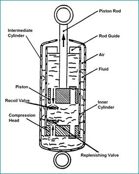
56 Monotube Damper Schematics Compression Head Chamber G Gas P G,V G Oil, P 1,V 1 Chamber 1 Oil P 1, V 1 Q 13 Separator Piston Oil P 3,V 3 Chamber 3 Oil Q 12 Piston Oil Q 12 Ga s Chamber 2 P G, V G P 2,V 2 P 2,V 2 Piston rod Chamber G Remote Reservoir and Twin Tube are functionally similar a) Monotube (b) Remote Reservoir Schematics of monotube and remote reservoir dampers.
57 Monotube Low Speed Damping Force Low speed flow is normally controlled by an orifice. Oil Deflection Disc Stack &X Low Pressu re Deflection Disc Stop Deflection Disc Spacer Types of orifices: Hole in piston (with or without one way valve) Notch in disc Coin land Flow Through Bleed Orifice Leak age Flow Oil High Pressure Piston Retaining Nut Piston For turbulent flow: P = C d Q A eff 2 ρ 2 S chematic of low speed compression valve flow. As flow rate Q is equal to relative velocity of the piston times the area of the piston in compression (piston area rod area in rebound): At low speeds, total DAMPER force might be influenced more by friction and gas spring, then damping. Orifice damping force is proportional to the square of the piston speed.
58 Monotube Mid Speed Damping Force Mid speed flow is normally controlled by an flow compensating device. Oil & X Low Pressure Types of flow compensating devices: Deflection Discs ( typically stacked) Blow off valve (helical spring) Preloaded on the valve determines the cracking pressure, and hence the force at which they come into play. Define the knee in FV curve. Deflection Disc Flow Oil High Pressure Schematic of mid speed compression valve flow. Preload: Disc, shape of piston, often expressed in degree. Disc, spring to preload (sometimes found in adjustable race dampers) Spring, amount of initial deflection. Torque variation on jam nut can often vary preload. Undesired for production damper, With flow compensation pressure drop and force are proportional to velocity.
59 Monotube High Speed Damping Force Oil Low Pressure High speed flow is controlled by restrictions in effective flow area. i.e. effectively orifice flow. &X Flow restrictions, typically which ever has smaller effective area: Limit of disc or blow off valve travel. Orifice size through piston. Deflection Disc Flow Oil High Pressure As per low speed damping, pressure drop and force are proportional to velocity squared. Rebound damping and pressure drops across compression heads (foot valves) are similar to those discussed here. S chematic of high speed compression valve flow.
")
60 Dead Length Dead Length = A + B + C + D + E + F Max Travel = (Extended Length Dead Length) /2

61 Performance Measurement Various wave forms can be used to test, sinusoidal, step, triangular, track measurements, etc. Data captured for further manipulation. Easy to vary input freq. and amplitude. Computer Controlled Servo Hydraulic Shock Dyno Offers potential to perform low speed friction and gas spring check, which are removed from the damper forces, to produce damping charts. Need to know which algorithms are used.
62 Sinusoidal Input 3 2 Displacement 2 4 Velocity Time Time Sine Wave Displacement Input Corresponding Velocity Input Sinusoid, most Common Input form for Shock Testing Displacement = X sin (ωt) Velocity = V = X ω cos (ω t) Where w = 2 * π * Freq. Peak Velocity = X * ω Typically test at a given stroke and vary frequency. Suspension normally respondes at forcing freq. and natural frequencies. So should we test at bounce and wheel hop freq.?
63 Test Outputs Force 1 3 Force Displacement Velocity Force-Displacement Plot Force-Velocity Plot
64 Peak Force - Peak Velocity Plot Speed Development Test Force lbs Speed Audit Test Velocity in/sec Typical Peak Force - Peak Velocity Plot
65 Monotube vs. Twin Tube Advantages / Disadvantages of Twin Tube and Monotube Shock Absorbers Twin Tube Monotube Cost Less More Weight More Less Packaging Less dead length. Minor external damage OK. Must be mounted upright. Longer dead length. Minor external damage can cause failure. Can be mounted in any position Rod Reaction Force Low High Sealing Requirements Moderate High Fade Performance Moderate Better Twin tube has greater sensitivity to compressibility and hence acceleration.
66 Thanks for your attention Questions??
SUMMARY OF STANDARD K&C TESTS AND REPORTED RESULTS
 Description of K&C Tests SUMMARY OF STANDARD K&C TESTS AND REPORTED RESULTS The Morse Measurements K&C test facility is the first of its kind to be independently operated and made publicly available in
Torque steer effects resulting from tyre aligning torque Effect of kinematics and elastokinematics
 P refa c e Tyres of suspension and drive 1.1 General characteristics of wheel suspensions 1.2 Independent wheel suspensions- general 1.2.1 Requirements 1.2.2 Double wishbone suspensions 1.2.3 McPherson
A double-wishbone type suspension is used in the front. A multi-link type suspension is used in the rear. Tread* mm (in.) 1560 (61.
 1560 (61.") CHASSIS SUSPENSION AND AXLE CH-69 SUSPENSION AND AXLE SUSPENSION 1. General A double-wishbone type suspension is used in the front. A multi-link type suspension is used in the rear. 08D0CH111Z Specifications
CHASSIS SUSPENSION AND AXLE CH-69 SUSPENSION AND AXLE SUSPENSION 1. General A double-wishbone type suspension is used in the front. A multi-link type suspension is used in the rear. 08D0CH111Z Specifications
ROLL CENTER You can adjust the front and rear roll centers of the XB8 by changing the mounting locations of various components.
 Your XRAY XB8 luxury nitro buggy is a top competition, precision racing machine that features multiple adjustments that allow you to set up for any track condition. The XB8 includes innovative set-up features
Design and Analysis of suspension system components
 Design and Analysis of suspension system components Manohar Gade 1, Rayees Shaikh 2, Deepak Bijamwar 3, Shubham Jambale 4, Vikram Kulkarni 5 1 Student, Department of Mechanical Engineering, D Y Patil college
Kinematic Analysis of Roll Motion for a Strut/SLA Suspension System Yung Chang Chen, Po Yi Tsai, I An Lai
 Kinematic Analysis of Roll Motion for a Strut/SLA Suspension System Yung Chang Chen, Po Yi Tsai, I An Lai Abstract The roll center is one of the key parameters for designing a suspension. Several driving
Shock Absorbers What is Ride Control Vehicle Dynamics Suspension System Shock Absorbers Struts Terminology
 Home Tech Support Shock Absorbers Shock Absorbers What is Ride Control Vehicle Dynamics Suspension System Shock Absorbers Struts Terminology A BRIEF HISTORY These first shock absorbers were simply two
Designing and Hard Point Optimization of Suspension System of a Three-Wheel Hybrid Vehicle
 ISSN (O): 2393-8609 International Journal of Aerospace and Mechanical Engineering Designing and Hard Point Optimization of Suspension System of a Three-Wheel Hybrid Vehicle Gomish Chawla B.Tech Automotive
Suspension systems and components
 Suspension systems and components 2of 42 Objectives To provide good ride and handling performance vertical compliance providing chassis isolation ensuring that the wheels follow the road profile very little
Cane Creek Double Barrel Instructions
 Cane Creek Double Barrel Instructions Congratulations on your purchase of the Cane Creek Double Barrel rear shock. Developed in partnership with Öhlins Racing, the Double Barrel brings revolutionary suspension
Design and Integration of Suspension, Brake and Steering Systems for a Formula SAE Race Car
 Design and Integration of Suspension, Brake and Steering Systems for a Formula SAE Race Car Mark Holveck 01, Rodolphe Poussot 00, Harris Yong 00 Final Report May 5, 2000 MAE 340/440 Advisor: Prof. S. Bogdonoff
Design, Modelling & Analysis of Double Wishbone Suspension System
 Design, Modelling & Analysis of Double Wishbone Suspension System 1 Nikita Gawai, 2 Deepak Yadav, 3 Shweta Chavan, 4 Apoorva Lele, 5 Shreyash Dalvi Thakur College of Engineering & Technology, Kandivali
Jim Kasprzak 36 years racing experience Developed 7-post testing for GM Racing Currently Race Engineer for SRT Viper Expertise includes:
 Jim Kasprzak 36 years racing experience Developed 7-post testing for GM Racing Currently Race Engineer for SRT Viper Expertise includes: Race Engineering 7 post testing Suspension Engineering Shock design,
2004 SUSPENSION. Wheel Alignment - Corvette. Caster Cross +/ / Fastener Tightening Specifications Specification Application
 2004 SUSPENSION Wheel Alignment - Corvette SPECIFICATIONS WHEEL ALIGNMENT SPECIFICATIONS Wheel Alignment Specifications Camber Cross Caster Cross Suspension Camber Tolerance Caster Tolerance FE1 & FE3
SUSPENSION 2-1 SUSPENSION TABLE OF CONTENTS
 XJ SUSPENSION 2-1 SUSPENSION TABLE OF CONTENTS page ALIGNMENT... 1 FRONT SUSPENSION... 7 page REAR SUSPENSION... 16 ALIGNMENT TABLE OF CONTENTS page AND WHEEL ALIGNMENT...1 DIAGNOSIS AND TESTING SUSPENSION
Dynamic Analysis of Double Wishbone and Double Wishbone with S Link + Toe Link
 RESEARCH ARTICLE OPEN ACCESS Dynamic Analysis of Double Wishbone and Double Wishbone with S Link + Toe Link Rajkumar Kewat, Anil Kumar Kundu,Kuldeep Kumar,Rohit Lather, Mohit Tomar RJIT, B.S.F ACADEMY
General Vehicle Information
 Vehicle #3921 Chevrolet Equinox (2CNALBEW8A6XXXXXX) Inspection Date: 1-Feb-211 Year 21 Make Model Body Style HVE Display Name: Year Range: Sisters and Clones: Vehicle Category: Vehicle Class: VIN: Date
SUSPENSION 2-1 SUSPENSION CONTENTS
 ZJ SUSPENSION 2-1 SUSPENSION CONTENTS page ALIGNMENT... 1 FRONT SUSPENSION... 6 page REAR SUSPENSION... 14 ALIGNMENT INDEX page GENERAL INFORMATION WHEEL ALIGNMENT... 1 DIAGNOSIS AND TESTING SUSPENSION
II YEAR AUTOMOBILE ENGINEERING AT AUTOMOTIVE CHASSIS QUESTION BANK UNIT I - LAYOUT, FRAME, FRONT AXLE AND STEERING SYSTEM
 II YEAR AUTOMOBILE ENGINEERING AT 6402 - AUTOMOTIVE CHASSIS QUESTION BANK UNIT I - LAYOUT, FRAME, FRONT AXLE AND STEERING SYSTEM 1. Write about the requirements of frame and selection of cross section
Wheel Alignment Fundamentals
 CHAPTER 67 Wheel Alignment Fundamentals OBJECTIVES Upon completion of this chapter, you should be able to: Describe each wheel alignment angle. Tell which alignment angles cause wear or pull. KEY TERMS
SUSPENSION 2-1 SUSPENSION TABLE OF CONTENTS
 DN SUSPENSION 2-1 SUSPENSION TABLE OF CONTENTS page ALIGNMENT... 1 FRONT SUSPENSION - 4x2... 6 page FRONT SUSPENSION - 4x4... 14 REAR SUSPENSION... 23 ALIGNMENT TABLE OF CONTENTS page AND OPERATION WHEEL
SUSPENSION 2-1 SUSPENSION CONTENTS
 WJ SUSPENSION 2-1 SUSPENSION CONTENTS page ALIGNMENT... 1 FRONT SUSPENSION... 4 page REAR SUSPENSION... 15 ALIGNMENT INDEX page AND WHEEL ALIGNMENT... 1 SERVICE PROCEDURES PRE-ALIGNMENT... 2 AND WHEEL
DRIVE-CONTROL COMPONENTS
 3-1 DRIVE-CONTROL COMPONENTS CONTENTS FRONT SUSPENSION................... 2 Lower Arms............................... 5 Strut Assemblies........................... 6 REAR SUSPENSION.....................
Welcome and enjoy tuning your Manitou ABS+ Compression Damping System! Purposefully engineered to raise your expectations.
 Welcome and enjoy tuning your Manitou ABS+ Compression Damping System! Purposefully engineered to raise your expectations. PLEASE READ SERVICE INSTRUCTIONS PRIOR TO BEGINNING WORK. While revalving your
Appendix X New Features in v2.4 B
 Appendix X New Features in v2.4 B Version 2.4B adds several features, which we have grouped into these categories: New Suspension Types or Options The program now allows for solid front axles and for several
MODELING SUSPENSION DAMPER MODULES USING LS-DYNA
 MODELING SUSPENSION DAMPER MODULES USING LS-DYNA Jason J. Tao Delphi Automotive Systems Energy & Chassis Systems Division 435 Cincinnati Street Dayton, OH 4548 Telephone: (937) 455-6298 E-mail: Jason.J.Tao@Delphiauto.com
SHOCK DYNAMOMETER: WHERE THE GRAPHS COME FROM
 SHOCK DYNAMOMETER: WHERE THE GRAPHS COME FROM Dampers are the hot race car component of the 90s. The two racing topics that were hot in the 80s, suspension geometry and data acquisition, have been absorbed
Wheel Alignment And Diagnostic Angles (STE04)
") Module 1 Wheel Alignments Wheel Alignment And Diagnostic Angles (STE04) Wheel Alignments o Conditions Requiring An Alignment o Conditions Requiring An Alignment (cont d) o Why We Do Checks And Alignments
Module 1 Wheel Alignments Wheel Alignment And Diagnostic Angles (STE04) Wheel Alignments o Conditions Requiring An Alignment o Conditions Requiring An Alignment (cont d) o Why We Do Checks And Alignments
DIAGNOSIS AND TESTING
 DIAGNOSIS AND TESTING SUSPENSION AND STEERING SYSTEM 2007 SUSPENSION Suspension - Nitro CONDITION POSSIBLE CAUSES CORRECTION FRONT END NOISE 1. Loose or worn wheel bearings. 1. Replace wheel bearings.
Suspension and Steering Alignment
 Suspension and Steering Alignment Matthew Whitten Brookhaven College Alignment Components Ride height Caster Camber Included angle Scrub radius Thrust angle Toe Turning radius Toe out on turns Steering
DESIGN AND ANALYSIS OF PUSH ROD ROCKER ARM SUSPENSION USING MONO SPRING
 Volume 114 No. 9 2017, 465-475 ISSN: 1311-8080 (printed version); ISSN: 1314-3395 (on-line version) url: http://www.ijpam.eu ijpam.eu DESIGN AND ANALYSIS OF PUSH ROD ROCKER ARM SUSPENSION USING MONO SPRING
SPMM OUTLINE SPECIFICATION - SP20016 issue 2 WHAT IS THE SPMM 5000?
 SPMM 5000 OUTLINE SPECIFICATION - SP20016 issue 2 WHAT IS THE SPMM 5000? The Suspension Parameter Measuring Machine (SPMM) is designed to measure the quasi-static suspension characteristics that are important
Unit HV04K Knowledge of Heavy Vehicle Chassis Units and Components
 Assessment Requirements Unit HV04K Knowledge of Heavy Vehicle Chassis Units and Components Content: Chassis layouts i. types of chassis ii. axle configurations iii. rear steered axles iv. self-steered
Technician Handbook. 453 Suspension, Steering and Handling. Technician Objectives
 Technician Objectives 1. List the six functions of suspension components.. 2. List the six major groups of components that require inspection. 3. Explain the inspection methods for the individual suspension
Fundamentals of Steering Systems ME5670
 Fundamentals of Steering Systems ME5670 Class timing Monday: 14:30 Hrs 16:00 Hrs Thursday: 16:30 Hrs 17:30 Hrs Lecture 3 Thomas Gillespie, Fundamentals of Vehicle Dynamics, SAE, 1992. http://www.me.utexas.edu/~longoria/vsdc/clog.html
Technical Report Lotus Elan Rear Suspension The Effect of Halfshaft Rubber Couplings. T. L. Duell. Prepared for The Elan Factory.
 Technical Report - 9 Lotus Elan Rear Suspension The Effect of Halfshaft Rubber Couplings by T. L. Duell Prepared for The Elan Factory May 24 Terry Duell consulting 19 Rylandes Drive, Gladstone Park Victoria
SUSPENSION 2-1 SUSPENSION CONTENTS
 TJ SUSPENSION 2-1 SUSPENSION CONTENTS page ALIGNMENT... 1 FRONT SUSPENSION... 6 page REAR SUSPENSION... 13 ALIGNMENT INDEX page DESCRIPTION AND OPERATION WHEEL ALIGNMENT... 1 DIAGNOSIS AND TESTING SUSPENSION
Roehrig Engineering, Inc.
 Roehrig Engineering, Inc. Home Contact Us Roehrig News New Products Products Software Downloads Technical Info Forums What Is a Shock Dynamometer? by Paul Haney, Sept. 9, 2004 Racers are beginning to realize
SUSPENSION 2-1 SUSPENSION CONTENTS
 DN SUSPENSION 2-1 SUSPENSION CONTENTS page ALIGNMENT... 1 FRONT SUSPENSION... 5 page REAR SUSPENSION... 13 ALIGNMENT INDEX page GENERAL INFORMATION WHEEL ALIGNMENT... 1 DIAGNOSIS AND TESTING PRE-ALIGNMENT
2008 MITSUBISHI LANCER EVOLUTION OFFERS SUPERCAR HANDLING. The 2008 Lancer Evolution succeeds a model that was considered one of the best-handling
 Contact: Janis Little Moe Durand Director, Product Communications Manager, Product Communications Tel: 714-372-6429 Tel: 714-372-6567 Email: JLittle@mmsa.com Email: M1Durand@mmsa.com 2008 MITSUBISHI LANCER
SUSPENSION 2-1 SUSPENSION CONTENTS
 TJ SUSPENSION 2-1 SUSPENSION CONTENTS page ALIGNMENT... 1 FRONT SUSPENSION... 5 page REAR SUSPENSION... 12 ALIGNMENT INDEX page GENERAL INFORMATION WHEEL ALIGNMENT... 1 DIAGNOSIS AND TESTING SUSPENSION
According to Newton's First Law, a moving body will continue moving in a straight line until it is acted
 RIDE CONTROL DEFINED According to Newton's First Law, a moving body will continue moving in a straight line until it is acted upon by another force. Newton's Second Law states that for each action there
STUDY OF ROLL CENTER SAURABH SINGH *, SAGAR SAHU ** ABSTRACT
 STUDY OF ROLL CENTER SAURABH SINGH *, SAGAR SAHU ** *, ** Mechanical engineering, NIT B ABSTRACT As our solar car aims to bring new green technology to cope up with the greatest challenge of modern era
STaSIS / Öhlins Motor Sport Suspension
 STaSIS / Öhlins Motor Sport Suspension Damper Model Information Öhlins LMJ Series Damper: Öhlins LMJ stock car shock absorbers are based on the race proven Öhlins 46HRC. A shock absorber featuring a large
SPMM OUTLINE SPECIFICATION - SP20016 issue 2 WHAT IS THE SPMM 5000?
 SPMM 5000 OUTLINE SPECIFICATION - SP20016 issue 2 WHAT IS THE SPMM 5000? The Suspension Parameter Measuring Machine (SPMM) is designed to measure the quasi-static suspension characteristics that are important
Determination of anti pitch geometry. acceleration [1/3]
![Determination of anti pitch geometry. acceleration [1/3]](/thumbs/83/87345496.jpg "Determination of anti pitch geometry. acceleration [1/3]") 1of 39 Determination of anti pitch geometry Similar to anti squat Opposite direction of D Alembert s forces. acceleration [1/3] Front wheel forces and effective pivot locations 2of 39 Determination of
1of 39 Determination of anti pitch geometry Similar to anti squat Opposite direction of D Alembert s forces. acceleration [1/3] Front wheel forces and effective pivot locations 2of 39 Determination of
GENERAL INFORMATION. Wheel Alignment Theory & Operation
 Fig. 1: Checking Steering Linkage GENERAL INFORMATION Wheel Alignment Theory & Operation ADJUSTMENTS NOTE: This article is intended for general information purposes only. This information may not apply
KINEMATICS OF REAR SUSPENSION SYSTEM FOR A BAJA ALL-TERRAIN VEHICLE.
 International Journal of Mechanical Engineering and Technology (IJMET) Volume 8, Issue 8, August 2017, pp. 164 171, Article ID: IJMET_08_08_019 Available online at http://www.iaeme.com/ijmet/issues.asp?jtype=ijmet&vtype=8&itype=8
1. SPECIFICATIONS 2. WHEEL ALIGNMENT
 441101 083 1. SPECIFICATIONS Front Suspension Rear Suspension Description Suspension type Spring type Shock absorber type Stabilizer bar type Suspension type Spring type Shock absorber type Stabilizer
Camber Angle. Wheel Alignment. Camber Split. Caster Angle. Caster and Ride Height. Toe Angle. AUMT Wheel Alignment
 AUMT 1316 - Wheel Alignment 11/15/11 Camber Angle Wheel Alignment Donald Jones Brookhaven College Camber Split Camber is the amount that the centerline of the wheel tilts away from true vertical when viewed
Chassis Dynamics. BMW Technical Training. BMW of North America, LLC Technical Training ST1115 8/1/12. Reference Manual. The Ultimate Driving Machine
 Reference Manual BMW Technical Training www.bmwcenternet.com The Ultimate Driving Machine Chassis Dynamics BMW of North America, LLC Technical Training ST1115 8/1/12 Information Status: August 01, 2012
Basic Wheel Alignment Techniques
 Basic Wheel Alignment Techniques MASTERING THE BASICS: Modern steering and suspension systems are great examples of solid geometry at work. Wheel alignment integrates all the factors of steering and suspension
1. SPECIFICATIONS 2. WHEEL ALIGNMENT Front Suspension. (gas type) Rear Suspension. (gas type)
 Rear Suspension. (gas type)") 441101 053 1. SPECIFICATIONS Front Suspension Rear Suspension Description Suspension type Spring type Shock absorber type Stabilizer bar type Suspension type Spring type Shock absorber type Stabilizer
441101 053 1. SPECIFICATIONS Front Suspension Rear Suspension Description Suspension type Spring type Shock absorber type Stabilizer bar type Suspension type Spring type Shock absorber type Stabilizer
2. MEASURE VEHICLE HEIGHT. (b) Measure the vehicle height. Measurement points: C: Ground clearance of front wheel center
 Measure the vehicle height. Measurement points: C: Ground clearance of front wheel center") ADJUSTMENT If the wheel alignment has been adjusted, and if suspension or underbody components have been removed/installed or replaced, be sure to perform the following initialization procedure in order
ADJUSTMENT If the wheel alignment has been adjusted, and if suspension or underbody components have been removed/installed or replaced, be sure to perform the following initialization procedure in order
Wheel Alignment Defined
 Wheel Alignment Defined While it's often referred to simply as an "alignment" or "wheel alignment," it's really complex suspension angles that are being measured and a variety of suspension components
Why do cars need Alignment
 Why do cars need Alignment The main purpose of wheel alignment is to make the tires roll without Scuffing, slipping, or dragging under all operating conditions. Caster Camber Toe Steering axis inclination
Shock manual V3.1 ENGLISH
 Shock manual V3.1 ENGLISH 2 Shock manual v3.1 INDEX Page Hyperpro Shock Overview 4 Maintenance 5 Rear Shock unit, removal and installation M1 Mono shock (& Telelever front) 6 M2 Twin shock 6 M3 Link system
Chapter-3. Wheel Alignment Wheel Kinematics and Compliance Steering Performance Criteria for Handling
 Chapter-3 Wheel Alignment Wheel Kinematics and Compliance Steering Performance Criteria for Handling Components of Suspension Linkage Bearings, Bushings Springs Dampers Wheel Geometry Wheel Geometry Wheel
VEHICLE HANDLING BASICS
 RACE ENGINEERING ACADEMY VEHICLE HANDLING BASICS INTRODUCTION BY Dejan Ninic BE (Mech) PhD ENVIRAGE VEHICLE HANDLING DEFINITIONS STABILITY BALANCE VEHICLE DYNAMICS RESPONSE GRIP VEHICLE HANDLING DEFINITIONS
The Shock Absorber Handbook Second Edition
 The Shock Absorber Handbook Second Edition John C. Dixon, Ph.D, F.I.Mech.E., F.R.Ae.S. Senior Lecturer in Engineering Mechanics The Open University, Great Britain IICIUTIHHIIL BICINTINNIIM. John Wiley
SRI VIDYA COLLEGE OF ENGINEERING & TECHNOLOGY DEPARTMENT OF MECHANICAL ENGINEERING. ME AUTOMOBILE ENGINEERING Question Bank
 SRI VIDYA COLLEGE OF ENGINEERING & TECHNOLOGY DEPARTMENT OF MECHANICAL ENGINEERING ME6602 - AUTOMOBILE ENGINEERING Question Bank UNIT-4 - STEERING, BREAKS AND SUSPENSION PART-A 1. Define wheel track and
STEERING SYSTEM Introduction
 STEERING SYSTEM Introduction The steering makes it possible to change direction. The steering must be reliable and safe; there must not be too much play in the steering. It must be possible to steer accurately.
CHAPTER 6 MECHANICAL SHOCK TESTS ON DIP-PCB ASSEMBLY
 135 CHAPTER 6 MECHANICAL SHOCK TESTS ON DIP-PCB ASSEMBLY 6.1 INTRODUCTION Shock is often defined as a rapid transfer of energy to a mechanical system, which results in a significant increase in the stress,
Design of Suspension and Steering system for an All-Terrain Vehicle and their Interdependence
 Design of Suspension and Steering system for an All-Terrain Vehicle and their Interdependence Saurabh Wanganekar 1, Chinmay Sapkale 2, Priyanka Chothe 3, Reshma Rohakale 4,Samadhan Bhosale 5 1 Student,Department
The Black Crack Report
 addiction you don t want to fight Happy Holidays This year has gone by in the blink of an eye. It is hard to believe that I am already planning for 2011, but I am looking forward to it. I want to personally
Steering and Suspension
 The Steering and Suspension system is engineered to allow the vehicle to turn and absorb road irregularities. The suspension is comprised of springs, suspension arms or links and shock dampers. These components
Solar Car Suspension Design Considerations for achieving an efficient and stable vehicle
 Innovators Educational Foundation Solar Car Suspension Design Considerations for achieving an efficient and stable vehicle Solar Car Conference, February 1-3, 2019 Southern Illinois University, Edwardsville,
Design and optimization of Double wishbone suspension system for ATVs
 Design and optimization of Double wishbone suspension system for ATVs Shantanu Garud 1, Pritam Nagare 2, Rohit Kusalkar 3, Vijaysingh Gadhave 4, Ajinkya Sawant 5 1,2,3,4Dept of Mechanical Engineering,
X4-X7 Hyper 600cc Chassis Setup Guide
 Suggested Starting Setup on a Normal Condition 1/6 or 1/8 Mile Track, Winged Left Front Right Front Left Rear Right Rear Torsion Bar Size (+ Turns).675 (+0).675 (+0).725 (+0).750 (+1) Coil Size (+ Turns)
ATASA 5 th. Wheel Alignment. Please Read The Summary. ATASA 5 TH Study Guide Chapter 47 Pages: Wheel Alignment 64 Points
 ATASA 5 TH Study Guide Chapter 47 Pages: 1403 1423 64 Points Please Read The Summary Before We Begin Keeping in mind the Career Cluster of Transportation, Distribution & Logistics Ask yourself: What careers
iracing.com Williams-Toyota FW31 Quick Car Setup Guide
 iracing.com Williams-Toyota FW31 Quick Car Setup Guide In this guide we will briefly explain a number of key setup parameters which are distinct to the FW31 and which are new to iracing vehicles. We hope
Integrated damper suspension system
 Integrated damper suspension system Introduction Vehicle dynamics and damping Converting kinetic energy into Thermal energy Controllong extension stroke of the suspension Integrated suspension/damping
BASIC WHEEL ALIGNMENT
 BASIC WHEEL ALIGNMENT You have got to know all the angles. Correct wheel alignment plays a huge part in a customer s positive driving experience. Having it dialed in correctly is essential to proper vehicle
Chapter. Suspension System Technology. Basic Suspension System. Functions of a Suspension System
 76 Chapter Suspension System Technology Name Instructor Date Score Objective: After studying this chapter, you will be able to explain the construction and operation of modern suspension systems. Basic
1990 INTEGRA CHASSIS. - Double- Wishbone Front Suspension -
 c 1990 INTEGRA CHASSIS DESIGN OBJECTIVES In designing the new Integra's chassis, the goals were: a high degree oflinear stability, precise and quick transient response, a favorable front/rear balance for
Modern Auto Tech Study Guide Chapter 67 & 69 Pages Suspension & Steering 32 Points. Automotive Service
 Modern Auto Tech Study Guide Chapter 67 & 69 Pages 1280 1346 Suspension & Steering 32 Points Automotive Service 1. The system allows a vehicle s tires & wheels to move up and down as they roll. Steering
Part 1. The three levels to understanding how to achieve maximize traction.
 Notes for the 2017 Prepare to Win Seminar Part 1. The three levels to understanding how to achieve maximize traction. Level 1 Understanding Weight Transfer and Tire Efficiency Principle #1 Total weight
The Mark Ortiz Automotive
 July 2004 WELCOME Mark Ortiz Automotive is a chassis consulting service primarily serving oval track and road racers. This newsletter is a free service intended to benefit racers and enthusiasts by offering
WHEEL ALIGNMENT SPECIFICATIONS & PROCEDURES
 WHEEL ALIGNMENT SPECIFICATIONS & PROCEDURES 1988 Jeep Cherokee 1988 Wheel Alignment INTRODUCTION PRE-ALIGNMENT VEHICLE CHECKS Prior to making wheel alignment adjustments, check and adjust the following
The High Performance, High Payload Driving School Car Based on a 1995 BMW 318is. Kevin Chow Bob Matarese Harris Yong
 Based on a 1995 BMW 318is Kevin Chow Bob Matarese Harris Yong ME 227 Final Project June 6, 22 1 Project Basis and Goal The goal behind this particular project was to improve upon the vehicle dynamics of
Design, Analysis, Simulation and Validation of Suspension System for an Electric All-Terrain Vehicle (ATV)
") Design, Analysis, Simulation and Validation of Suspension System for an Electric All-Terrain Vehicle (ATV) Akshay G Bharadwaj 1, Sujay M 2, Lohith E 3, Karthik S 4 B. E Student, Dept. of Mechanical Engineering,
Design, Analysis, Simulation and Validation of Suspension System for an Electric All-Terrain Vehicle (ATV) Akshay G Bharadwaj 1, Sujay M 2, Lohith E 3, Karthik S 4 B. E Student, Dept. of Mechanical Engineering,
FRONT SUSPENSION GROUP CONTENTS GENERAL INFORMATION ON-VEHICLE SERVICE FASTENER TIGHTENING SPECIFICATIONS...
 33-1 GROUP 33 FRONT SUSPENSION CONTENTS GENERAL INFORMATION 33-2 FASTENER TIGHTENING SPECIFICATIONS 33-2 GENERAL SPECIFICATIONS 33-3 SERVICE SPECIFICATIONS 33-3 LUBRICANTS 33-3 DIAGNOSIS 33-4 INTRODUCTION
EFFECTIVE SOLUTIONS FOR SHOCK AND VIBRATION CONTROL
 EFFECTIVE SOLUTIONS FOR SHOCK AND VIBRATION CONTROL Part 1 Alan Klembczyk TAYLOR DEVICES, INC. North Tonawanda, NY Part 2 Herb LeKuch Shocktech / 901D Monsey, NY SAVIAC Tutorial 2009 Part 1 OUTLINE Introduction
Spring manual V3.1 ENGLISH
 Spring manual V3.1 ENGLISH HYPERPRO TOOLS, used in this manual: Tool Description Part no. A, B, C Cartridge fork spring removal tool kit HP-T01 D Big Piston Fork end cap socket 45mm HP-T102 E Big Piston
1. Rear Suspension (Multi-link Type)
") (MULTI-LINK TYPE) 1. Rear Suspension (Multi-link Type) A: GENERAL The rear suspension is a multilink type. The suspension on each side consists of a rear arm, front link, upper link, rear link, sub frame
(MULTI-LINK TYPE) 1. Rear Suspension (Multi-link Type) A: GENERAL The rear suspension is a multilink type. The suspension on each side consists of a rear arm, front link, upper link, rear link, sub frame
Experimental Investigation of Effects of Shock Absorber Mounting Angle on Damping Characterstics
 Experimental Investigation of Effects of Shock Absorber Mounting Angle on Damping Characterstics Tanmay P. Dobhada Tushar S. Dhaspatil Prof. S S Hirmukhe Mauli P. Khapale Abstract: A shock absorber is
FRONT SUSPENSION AND STEERING LINKAGE
 A FRONT SUSPENSION AND STEERING LINKAGE CONTENTS GROUP 2 Page LOWER BALL JOINTS 12 LOWER CONTROL ARM AND SHAFT... 9 LOWER CONTROL ARM STRUT 12 PRE-ALIGNMENT INSPECTION Height Adjustment., 4 RUBBER ISOLATED
2011+ Adjustable Tie-rod Ends (Mm5TR-2)
") 3430 Sacramento Dr., Unit D San Luis Obispo, CA 93401 Telephone: 805/544-8748 Fax: 805/544-8645 www.maximummotorsports.com 2011+ Adjustable Tie-rod Ends (Mm5TR-2) Instructions 1. Set the parking brake
3430 Sacramento Dr., Unit D San Luis Obispo, CA 93401 Telephone: 805/544-8748 Fax: 805/544-8645 www.maximummotorsports.com 2011+ Adjustable Tie-rod Ends (Mm5TR-2) Instructions 1. Set the parking brake
International Journal of Scientific & Engineering Research Volume 8, Issue 10, October-2017 ISSN
 309 Design and Analysis of Suspension System for a Formula Style Car Anshul Kunwar 1, Mohit Nagpal 2, Geetanjali Raghav 3 1 Student, Department of Mechanical Engineering, DIT University, Dehradun-248009
Vehicle Load Transfer. Wm Harbin Technical Director BND TechSource
 Vehicle Load Transfer Wm Harbin Technical Director BND TechSource 1 Vehicle Load Transfer Part I General Load Transfer Factors in Vehicle Dynamics Within any modern vehicle suspension there are many factors
Chapter 4. Vehicle Testing
 Chapter 4 Vehicle Testing The purpose of this chapter is to describe the field testing of the controllable dampers on a Volvo VN heavy truck. The first part of this chapter describes the test vehicle used
GLOSSARY. Air Actuator
 GLOSSARY A Air Actuator A device which induces action or motion with compressed air being the medium through which the power is transmitted, similar in function to a hydraulic cylinder. Air Spring Assembly
Design Methodology of Steering System for All-Terrain Vehicles
 Design Methodology of Steering System for All-Terrain Vehicles Dr. V.K. Saini*, Prof. Sunil Kumar Amit Kumar Shakya #1, Harshit Mishra #2 *Head of Dep t of Mechanical Engineering, IMS Engineering College,
Mathematical Modelling and Simulation Of Semi- Active Suspension System For An 8 8 Armoured Wheeled Vehicle With 11 DOF
 Mathematical Modelling and Simulation Of Semi- Active Suspension System For An 8 8 Armoured Wheeled Vehicle With 11 DOF Sujithkumar M Sc C, V V Jagirdar Sc D and MW Trikande Sc G VRDE, Ahmednagar Maharashtra-414006,
Steering drift and wheel movement during braking: static and dynamic measurements
 11 Steering drift and wheel movement during braking: static and dynamic measurements J Klaps1 and AJDay2* 1Ford Motor Company, Ford-Werke Aktiengesellschaft, Fabriekente Genk, Genk, Belgium 2University
SECTION 2C FRONT SUSPENSION TABLE OF CONTENTS
 SECTION 2C FRONT SUSPENSION TABLE OF CONTENTS Description and Operation... 2C-2 Front Suspension... 2C-2 Specifications... 2C-4 Component Locator... 2C-5 Front Suspension Assembly... 2C-5 Cross-Sectional
FRONT SUSPENSION GROUP CONTENTS GENERAL INFORMATION FASTENER TIGHTENING SPECIFICATIONS GENERAL SPECIFICATIONS...
 33-1 GROUP 33 FRONT SUSPENSION CONTENTS GENERAL INFORMATION 33-2 FASTENER TIGHTENING SPECIFICATIONS 33-2 GENERAL SPECIFICATIONS 33-3 SERVICE SPECIFICATIONS 33-3 DIAGNOSIS 33-4 INTRODUCTION TO DIAGNOSIS
 www.whiteline.com.au ROCK ROLL CENTRE KIT ESSENTIAL FOR LOWERED VEHICLES Recommended for race use only WHITELINE diagnosed a mediocre MacPherson front suspension with poor roll centre control and excessive
Installing and Squaring the Rear Axle
 Installing and Squaring the Rear Axle 1. Level the GF1 frame; both front to back and left to right. 2. Install the Jacob s Ladder in the frame. 3. Insert your Torsion Bars and tighten the torsion arms,
LIKE-NEW SAFETY AND HANDLING
 BRING YOUR VEHICLE BACK TO LIKE-NEW SAFETY AND HANDLING PROTECT THE ONES YOU LOVE BY REPLACING DEGRADED SHOCKS AND STRUTS SHOCKS & STRUTS 2 Like-New Safety and Handling What Do Shocks and Struts Do? STAY