Chapter-3. Wheel Alignment Wheel Kinematics and Compliance Steering Performance Criteria for Handling
|
|
|
- Maximilian Hines
- 5 years ago
- Views:
Transcription
1 Chapter-3 Wheel Alignment Wheel Kinematics and Compliance Steering Performance Criteria for Handling

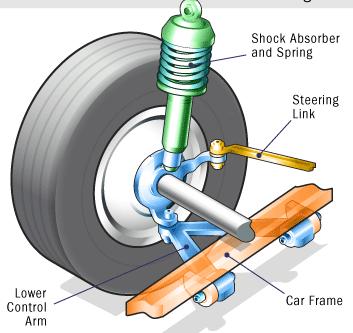
2 Components of Suspension Linkage Bearings, Bushings Springs Dampers

3 Wheel Geometry

4 Wheel Geometry
5 Wheel Geometry
6 Wheel Alignment A wheel Alignment is the adjustment of the suspension and steering to ensure proper vehicle handling with minimum tire wear A change in alignment angles may result from one or more of the following factors Wear of the steering and suspension components Bent or damaged steering and suspension parts Sagging springs, which can change the ride height of the vehicle and therefore the alignment angles
7 Pull Alignment- Related Problems A pull is generally defined as a definite tug on the steering wheel toward the left or the right while driving straight on a level road Wander Wheel Alignment 1 Wheel Alignment 2 A wander is a condition in which almost constant steering wheel corrections by the driver are necessary to maintain a straight-ahead direction on a straight level road


8 Camber Camber is the inward or outward tilt of the wheels from true vertical as viewed from the front or rear of the vehicle Camber
9 Camber If the top of the tire is tilted out, then camber is positive If the top of the tire is tilted in, then camber is negative If the tilt of the wheel is truly vertical, camber is zero Camber is measured in degrees or fraction of degrees Camber can cause tire wear if not correct Excessive positive camber causes scuffing and wear on the outside edge of the tire Excessive negative camber causes scuffing and wear on the inside edge of the tire
10
11

12 Camber Incorrect camber can cause excessive wear on wheel bearings. Many vehicle manufacturers specify positive camber so that the vehicle weight is applied to the larger inner wheel bearing and spindle. As the vehicle is loaded or when the spring sag, camber usually decreases. If camber is kept positive, then the running camber is kept near zero degrees for best tire life
13 Camber Camber can cause pull (Camber Thrust) if it is unequal side to side. The vehicle will pull toward the side with the most positive (or least negative) camber. A difference of more than half a degree from one side to the other will cause the vehicle to pull

14 Camber Thrust The lateral force that arises due to an inclination of the tyre from the vertical is referred to as camber thrust. Generation of lateral force due to camber angle Generation of lateral force due to camber angle
15 Camber Changes Vertical Load Positive Cambered Wheels move inward when loaded


16 Camber Change Lateral Load Transfer and compression of Suspension, hence change in Camber Upper Control Arm Y Instantaneous Centre (kinematic) Z

17 Camber Changes
18 Camber Change Effect in Cornering Centrifugal Force mv 2 /R Camber Thrust Lateral Force Vehicle Having Positive Camber Camber Changes Happen Vehicle Understeers
19 Camber Change Effect in Cornering Centrifugal Force mv 2 /R Camber Thrust Lateral Force Vehicle Having Negative Camber Camber Changes Happen Vehicle Oversteers
20 Suspension Travel
21 Parallel Wheel Travel Bump Travel Vertical distance wheel is able to move up from static position, with reference to vehicles sprung mass Rebound Travel Vertical distance wheel is able to move down from static position with reference to vehicles sprung mass
22 Camber Change

23 Parallel Opposite Wheel Travel
24 Camber Change
25 Steering Angle and Bump Steer

26 Camber Change in Solid Axle Suspension Solid axle suspension characteristics: Camber change on bumps, none on rebound, large unsprung weight
27 Camber Camber is not adjustable on many vehicles If camber is adjustable, the change is made by moving the upper or the lower control arm or strut assembly by means of one of the following methods Shims Eccentric Cams Slots Camber should be equal on both sides; however, if camber cannot be adjusted exactly equal, make certain that there is more camber on the front of the left side to help compensate for the road crown (half a degree maximum difference) in LHD, opposite for RHD
28 Toe Toe is the difference in distance between the front and rear of the tires

29 Most vehicle manufacturers specify a slight amount of toe in to compensate for the natural tendency of the front wheels to spread apart (become toed-out) due to the centrifugal force of the rolling wheels acting on the steering linkage-rear wheel driven Some manufacturers of front wheel drive vehicles specify a toe-out setting to compensate for the toe-in forces created by the engine drive forces on the front wheels Normal wear to the tie rod ends and other steering linkage parts usually causes toe-out Rear wheel Drive Wheels toe out during running
30 Front wheel Drive Toe Drive Axles Toe in during running Toe

31 Toe Toe is measured in fractions of degrees or in fractions of an inch (usually sixteenths), millimeters(mm), or decimals of an inch (such as 0.06 ) Incorrect toe is the major cause of excessive tire wear Toe causes camber type wear on one side of the tire if not correct


32 Toe Incorrect front toe does not cause a pull condition. Incorrect toe on the front wheels is split equally as the vehicle is driven because the forces acting on the tires are exerted through the tie rod and steering linkages to both wheels Incorrect (unequal) rear toe can cause tire wear. If the toe of the rear wheels is not equal, the steering wheel will not be straight and will pull toward the side with the most toe-in

33 Toe Front toe adjustment must be made by adjusting the tie rod sleeves correctly

34 Caster Caster is the forward or rearward tilt of the steering axis in reference to a vertical line as viewed from the side of the vehicle. Steering axis is defined as the line drawn through the upper and lower steering pivot points. On an SLA suspension system, the upper pivot is the upper ball joint and the lower pivot is the lower ball joint. On a MacPherson strut system, the upper pivot is the centre of the upper bearing mount and the lower pivot point is the lower ball joint. Zero Center means that the steering axis is straight up and down, also called zero degrees or perfectly vertical
 as viewed from the side Caster is measured in degrees of fractions of degrees")
35 Caster Positive caster is present when the upper suspension pivot point is behind the lower pivot point (ball joint) as viewed from the side Negative caster is present when the upper suspension pivot point is ahead of the lower pivot point (ball joint) as viewed from the side Caster is measured in degrees of fractions of degrees Caster
36

37 Caster- Camber Roll Caster is not a tire wearing angle, but positive caster does cause changes in camber during a turn. This condition is called camber roll

38 Caster is a stability angle Caster If caster is set positive, vehicle steering will be very stable (will tend to be straight with little steering wheel correction needed) and help with steering wheel If the caster is positive, the steering effort will increase with increasing positive caster. Greater road shocks will be felt by the driver when driving over rough road surfaces. Vehicles with as high as eleven degrees of positive caster usually use a steering dampener to control possible shimmy at high speeds and to dampen the snap-back of the spindle after a turn If caster is negative, or excessively unequal, the vehicle will not be as stable and will tend to wander. If a vehicle is heavily loaded in the rear, caster increase as shown

39 This movement may be due to vehicle inertia Z Caster Changes Z X Y Y Assume wheel is locked up X Y Caster Changes leads to camber change hence camber roll
40 Caster Change (Parallel Opposite)
41 Caster angle v/s Wheel Travel (Parallel)
42 Caster Caster could cause pull if unequal. The vehicle will pull toward the side with least positive caster Caster is not adjustable on many vehicles If caster is adjustable, the change is made by moving either the lower or the upper pivot point forward or backward by means of one of the following methods Shims Eccentric Cams Slots Strut rods
43 Caster Change and Aligning Moment Tyre Slip Angle Positive Caster point Centrifugal Force Side force Aligning Moment Lateral/Grip Force
44 Caster Change and Aligning Moment Tyre Slip Angle Positive Caster point Negative caster Aligning Moment
 is the inward tilt of the steering axis. SAI is also known as KPI and is the imaginary line drawn through the kingpin as viewed from the front")
45 Steering Axis Inclination (SAI) The steering axis is the angle formed between true vertical and an imaginary line drawn between the upper and lower pivot points of the spindle. Steering axis inclination (SAI) is the inward tilt of the steering axis. SAI is also known as KPI and is the imaginary line drawn through the kingpin as viewed from the front
.")
46 Steering Axis Inclination (SAI) The front view axis inclination angle add steering returnability by lifting the front axle in a turn. When the wheel is turned, you recognise the lifting of the vehicle (on the ball). If you press the ball, the turned wheel immediately goes into the straight ahead position.
47 Steering Axis Inclination (SAI)
48 Steering Geometry
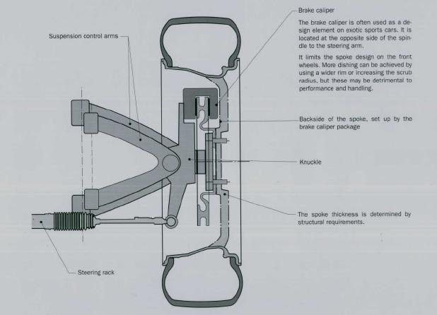
49 Scrub Radius
50 Effect of Scrub Radius on Steering Due to Road Disturbance Y Z Y Z X Wheels Toe Out X Wheels Toe in Y Y Positive Scrub Radius Disturbance Creates outboard moment Z Road Disturbance Rear Wheel Driven Negative Scrub Radius Disturbance Creates inboard moment Z
51 Effect of Scrub Radius on Steering Due to Road Disturbance Y Z Y Z Traction Force Wheels Toe in X X Wheels Toe out Y Y Positive Scrub Radius Traction Force Creates inboard moment Traction is greater than Road Disturbance Z Front Wheel Driven Negative Scrub Radius Traction Force Creates out board moment Z
52 Effect of Scrub Radius During Braking Y Z Y Z X Wheels Toe Out Wheels Toe in Braking Effort Positive scrub radius will cause the vehicle to veer towards the side with the greater effort Braking Effort Negative scrub radius will cause the vehicle to veer away from the side with the greater effort During braking, on any type of drive, if braking effort is greater on one side of the vehicle than the other, positive scrub radius will cause the vehicle to veer towards the side with the greater effort. Negative scrub radius will cause the vehicle to veer away from the side of greatest effort. How much it veers depends on the size of the scrub radius.
53 Scrub Radius and Diagonal Split Brake Vehicles with a diagonal-split brake system have negative scrub radius built into the steering geometry. If one half of the brake system fails, then the vehicle will tend to pull up in a straight line. Reaction due to braking produces a clockwise couple More Brake effort produces a couple as shown The braking force tries to turn counterclockwise

54 Scrub Radius Change
55 Scrub Radius v/s Wheel Travel

56 The included angle is the SAI added to the camber reading of the front wheel only. Included angle is an important angle to measure when diagnosing vehicle handling or tire wear problems Included Angle

57 Steering Knuckle
58 Wheel angles

59 Alignment Specifications at Curb Height
60 Suspension Kinematics A basic characteristic of suspension system is the change in orientation and position of the wheel under the wheel stroke, which is called kinematic characteristic and it strongly influences the handling and the stability of the vehicle Kinematic design of a suspension system involves determining the positions of hardpoints or kinematic design points Suspension design factors such as toe, camber and caster are decided by the location of hardpoints.
61 Compliance Compliance is deliberately introduced into the suspension systems through bushings to achieve good ride and handling. Bushings are rubber members provided in suspension and steering sub-systems to avoid metal-to-metal friction during kinematic motion. Two types of compliance are of interest lateral and longitudinal force compliance. Specific Bushings are required to have desirable stiffness in specific orientations to meet compliance
62
 affects toe and camber in braking and driving Z stiffness of rack_house bushing (steering sub-system) affects toe and camber under lateral forces")
63 For MacPherson Suspension Bush Stiffness Y stiffness of lca_front and lca_rear bushings affects toe and camber in braking and driving X stiffness of rack_house bushing (steering sub-system) affects toe and camber in braking and driving Z stiffness of rack_house bushing (steering sub-system) affects toe and camber under lateral forces
64 Elastomer/Rubber Bushes

65 Automobile Suspension


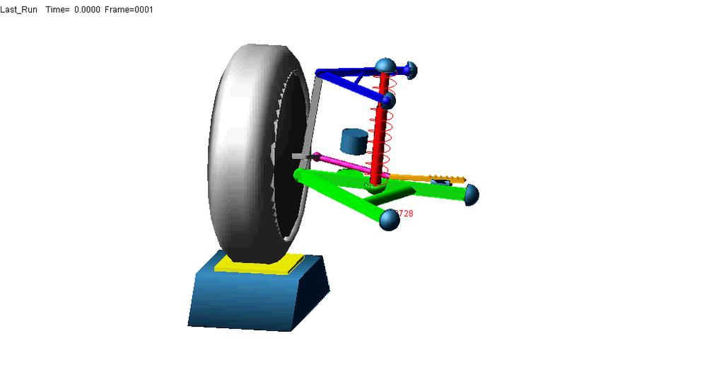
66 Kinematics and Compliance Test Rig with Test Vehicle


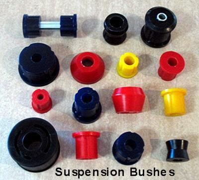
67 Suspension Bushes Single Bonded Bushes Provides a low cost pivot Double Bonded Bushes Provides a controlled stiffness pivot Interleaved Bushes Provides a controlled stiffness pivot with low torsional stiffness Hydraulic Bushes Provides damping control Applications: Damper bushes Engine torque rods Low cost suspension arms Applications: Damper bushes Suspension arms, where there is insufficient support for a single bonded bush Applications: High articulation positions Multi-link sports suspensions Applications: Front suspension compliance bushes Rear suspension trailing arm bushes Subframe mountings
68 Ackermann and Centre Point Steering The intention of Ackermann geometry is to avoid the need for tyres to slip sideways when following the path around a curve. The geometrical solution to this is for all wheels to have their axles arranged as radii of a circle with a common centre point. As the rear wheels are fixed, this centre point must be on a line extended from the rear axle. Intersecting the axes of the front wheels on this line as well requires that the inside front wheel is turned, when steering, through a greater angle than the outside wheel Low lateral Acceleration
69 Steering System Performance
70 Ackermann and Centre Point Steering A simple approximation to perfect Ackermann steering geometry may be generated by moving the steering pivot points inward so as to lie on a line drawn between the steering kingpins and the centre of the rear axle. The steering pivot points are joined by a rigid bar called the tie rod which can also be part of the steering mechanism, in the form of a rack and pinion for instance. With perfect Ackermann, at any angle of steering, the centre point of all of the circles traced by all wheels will lie at a common point. Note that this may be difficult to arrange in practice with simple linkages, and designers are advised to draw or analyze their steering systems over the full range of steering angles.
71 The kinematic geometry of the relay linkages and steering arms is usually not a parallelogram which would produce equal left and right steer angles, but rather a trapezoidal to more closely approximate Ackermann geometry which steers the inside wheel to a greater angle than outside wheel. Interference with the wheel usually prevents design for good Ackermann. Proper design of the Ackermann geometry is a function of the vehicle wheel base and tread.
72 Walter Korff Table Modern cars do not use pure Ackermann steering, partly because it ignores important dynamic and compliant effects, but the principle is sound for low speed manoeuvres. Since the results of most calculations must be graphically verified, one could use Mr. Korff's table as a starting point, then adjust the angles to remove real-world errors.

73 Steering Systems Rack and Pinion Steering System

74 Basic Steering Systems Recirculating Ball Steering System
75 Steering System Video Video
76 Steering System Hydraulic Power
77 Electric Power Assisted Steering
78 Steering Geometry Error Steering actions that arise from suspension motions are known as steering geometry error The errors are: bump steer (ride steer) and roll steer It is essential to run zero bump steer: if the wheel steers when it runs over a bump or when the car roll in a turn, the car will travel on a path that the driver did not intend
79 Bump Steer Bump (Ride) Steer
80 Bump(Ride) Steer Equipment
81 Zero Ride Steer-Desirable
82 Nonlinear ride steer-tie rod length incorrect
83 Roll Steer Behaviour Experimentally Measured on a Vehicle
84 Steering System Performance Measures The specific design of a steering system geometry has a well-recognized influence on steering performance measures such as Center feel Steering Returnability Steering Ratio Steering ratio to cornering Steering ratio to braking Steering efforts
85 Centre Feel Steering Centre Feel
86 Steering Returnability-Alignment Moment When the steering wheel is released, the wheels must return automatically to the straight-running position and must remain stable in this position Tyre Slip Angle

87 Tyre Slip Angle
88 Steering Kinematics Steering kinematics and axle design must be such that, although the driver receives feedback on the adhesion between wheels and road surface, the steering wheel is not subjected to any forces from the spring motion of the wheels or from motive forces (front wheel drive) Steering Axis inclination causes the front section of the vehicle to lift when the wheels are at an angle. This leads to a caster dependent on the steering angle Toe-in (toe-out) is a slip angle present even during straight running travel. This tensions the linkages and causes a rapid build-up of transverse forces when the wheels are at an angle Z Z Y X X
89 Steering Kinematics Caster produces a lever arm for side forces, i.e. speed dependent return torque (Alignment Torque) Kingpin offset determines the extent to which the steering system is affected by interference factors :brakes pulling unevenly, motive forces under traction/overrun in front wheel drive vehicles. In modern designs, the aim is to achieve a steering offset (Scrub Radius/Pivot Radius) which is zero to slightly negative

90 Caster Change and Aligning Moment Tyre Slip Angle Positive Caster point Centrifugal Force Side force Aligning Moment Lateral/Grip Force
91 Caster Change and Aligning Moment Tyre Slip Angle Positive Caster point Negative caster Aligning Moment
92 Self Aligning Moment M AT ( M M )cos v Zl Zr 2 2
93 Aligning Moment

94 Self Aligning Moment or Torque Castor line point
95 Steering Ratio The steering ratio is defined as the ratio of steering wheel rotation angle to steer angle at the road wheels. Normally these range from 15 or 20 to 1 on passenger cars, and to 1 on trucks. Steering ratio allow for easy steering of the front wheels. Low ratios such as 12:1 give quick but stiff steering where as high ratios such as 20:1 provide slow but easier steering Because of the compliance, with increasing steer angles, the actual steering ratio will be much more than designed ratio.
96 Steering Ratio Because of the compliance and steer torque gradients with increasing steer angles, the actual steering ratio may be as much as twice the designed ratio. Fig shows experimental measurements on a truck which illustrate the phenomenon
97 Understeer Gradient Measured at the Steering wheel and Road Wheel of a Truck
98 Understeer Gradient due to Steering
99 Steering Ratio for Cornering L V K ( ) R gr At high speeds for an understeered vehicle steering angle increases, for cornering at high speed, it is good to have smaller steering ratios
100 Active Steering Need for Active Steering When vehicle Yaws during Braking due to imbalanced braking forces Vehicles yaws due to split Mu Vehicle Aligning moment changes its direction due to caster change Steering Ratio should be small to reduce the yaw rate by steering in the opposite direction quickly Normal speeds and normal conditions, steering torque rate should not have steep gradient-reasonable steering ratio Hence, need for variable steering ratio
101 Active Steering Concept When driving at lower speeds - such as in city traffic, when parking or on winding mountain roads, Active Steering increases the size of the steering angle- Low steering ratio At medium speeds, steering is easier To ensure smoothness at higher speeds, as of around 120 to 140 km/h Active Steering becomes more indirect. Active Steering therefore reduces the amount of change in the steering angle for every movement of the steering wheel. This gives the driver the advantage of more precise steering at higher speeds, and ensures great stability and more comfort If the vehicle is threatened with instability, such as by oversteering or braking on a changeable surface, Active Steering helps to overcome it. For example, in order to reduce unsafe yaw, Active Steering can increase the angle of steering wheels faster than even the most expert driver.


102 Active Steering Concept At the heart of Active Steering system is the planetary gear set integrated into the steering column. An electric motor in the joint adjusts the front wheels' steering angle in proportion to the Sedan's current speed.
103 BMW Active Steering
104 Steering System Forces and Moments The ground reactions on the tire are described by three forces and moments, as follows: Normal force Aligning torque Tractive force Rolling resistance moment Lateral force Overturning moment On front-wheel-drive cars, an additional moment is imposed by the drive torque.

105 Normal Force Fz Lateral Force-Fy Longitudinal Force-Fx: Traction Force
 Rolling Resistance")
106 Overturning Moment Mx Slip Angle Camber Aligning Moment (Mz) Rolling Resistance Moment (My)
107 Steering System Forces and Moments The forces and moments imposed on the steering system emanate from those generated at the tire-road interface.
108 Steering Wheel Torque The reaction in the steering system is described by the moment produced on the steer axis, which must be resisted to control the wheel steer angle. The sum of moments from the left and right wheels acting through the steering linkages with their associated ratios and efficiencies account for the steering-wheel torque feedback to the driver.
109 Estimation of Steering Forces and Moments M v = Total moment from left and right wheels F zl, F zr =Vertical load on left and right wheels d= Lateral offset at the ground = Lateral Inclination Angle (KPI) = Steer Angle =Caster Angle
110 Steering Forces and Moments The moment arising from vertical force acting M M v L ( F F ) d sin sin ( F F ) d zl The moment arising from lateral force yl zr ( F F ) r tan yr zl zr sin cos The moment arising from traction force MT ( FXl FXr ) d Aligning Torque M AT 2 2 ( M Zl M Zr )cos v Rolling resistance and Overturning moments have second order effect and are neglected
111 Steering Torque Variation with Caster Steering Torque high for positive caster and low for negative caster
112 Steering Torque
113 Steering Torque
114 Moment about SA due to drive line Torque The torque in the driveline produces a moment about the steer axis. T M d SA F X F X r [ d cos cos rsin( )]
115 The lateral inclination and caster are small enough that the cosine function can be assumed unity. Hence M SA F X [ d r sin( )] The forward force introduces a moment in the steering system which opposes the steer angle trying to steer the vehicle out of turn-make the vehicle understeer. That is hwy in Front wheel drive vehicles toe out is provided
116 Steering Effort From the foregoing equations compute the steering moments Estimate the Effort from the driver The difference should be the effort developed by the Assist
117 EPAS- Modelling and Analysis
118 Aims and Objectives The aim is to develop a controller which fulfills the two primary functions of an EPAS system Reduce the amount of steering torque exerted by the driver Control the return-to-centre motion of the steering wheel

119 Manually Operated -Rack and Pinion Steering System Hand Steering wheel Intermediate shaft Steering Knuckle Steering arm Wheel
120 Manually Operated -Rack and Pinion Steering System Tactile and Visual feed back Hand Steering wheel Steering Shaft Intermediat e Shaft Pinion and Rack Tie Rod Steering Arm Road Wheel Hand wheel steering angle : HW Hand wheel torque: T HW Rack and Pinion Gear Ratio: G PR All the torque required for steering the road wheel needs to be developed by the driver Torque applied to overcom e the Road wheel torque load Road wheel Torque due to friction between Road wheel tyre and Road and Aligning moment acts as load Road wheel steered angle RW
121 Motor Assisted-Rack and Pinion Steering System (EPAS) Column Assisted Type
122 Steering Wheel Angle and Torque Sensor-EPAS The magnitude and direction of torque applied by the driver are sent by the torque sensor to the controller The amount of torque required to steer the road wheel is calculated from vehicle speed which is received as a signal by the controller The controller decides the assist torque to be developed by subtracting the hand wheel torque The assist torque to be developed is divided by gear ratio between motor shaft and steering shaft to get the motor torque to be developed Based on required motor torque, current value is calculated and supplied to the motor
123 Motor Assisted-Rack and Pinion Steering System-EPAS Vehicle Speed Signal Controller Motor signal Assist Motor Power to Motor Battery Hand steering wheel Hand wheel steering angle : HW Hand wheel torque: T HW Hand steering wheel angle and torque sensor Gear Ratio Motor to shaft Gear Ratio: Gp Interme diate Shaft The total torque applied is the sum of Hand wheel torque and Motor Torque Pinion and Rack Tie Rod Steering Arm Torque applied to overcom e the Road wheel torque load Road wheel Torque due to friction between Road wheel tyre and Road and Aligning moment acts as load T Road Wheel Road wheel steered angle
124 EPAS- Detailed Modelling Hand Wheel Torque applied- T HW Mass moment of inertia of Hand wheel with Steering Shaft- J HW Steering shaft torsional stiffness k SS and Damping Coefficient c SS Torque from Assist Motor: T AM Inertia of Gear and intermediate k shaft System: J IS GI c p Intermediate shaft Stiffness k IS Jp and Damping Coefficient c IS k Pinion inertia- J p p K OB C Pinion Shaft stiffness- k p J C Pinion damping -c M LT M R M RT p Mass of Rack- M R Mass of Tie Rods-M LT, M RT Inertia of Steering Arm J LSA, J RSA Wheel Inertia J LW, J RW Forces on tyres F, F LT J LSA J LW K LS A K LT T H W J HW J GI k ss c ss c IS T AM K IBJ K IBJ K OB C-Conversion from Rotary Linear or linear to Rotary motion J Motor C J RSA J RW K RS A K RT F RT
125 EPAS- Simplified Modelling Total Torque Torque Applied by Driver Torque to be Developed by Motor Torque on Pinion Shaft Force to Torque Conversion Force on Rack Torque to Force Conversion Torque from Road wheel
126 Steering Torque about Steering Axis Steering moments acting about Steer Axis are: 1. Steering Torque due to vertical forces: M V 2. Steering Torque due to Lateral Forces : M L 3. Steering Torque due to Traction Forces: M T 4. Aligning Moment: A T 5. Moment due to drive line torque for front wheel drive vehicle: M d
127 Steering Torque from Road Wheel T total ( About steering Axis ) M v M L M T M align M driveline J w c w w J c w w Wheel inertia about SA axis Tyre Damping Tyre angular accelerati on zaxis Tyre angular velocity zaxis
128 M M M M M T v L T AT d ( F ( F ( F ( F ( F zl ( M F [ d x zl yl xl F zl F F zr zl ) d ( C Estimation of Road Torque ) d sin sin ( F ) r tan ) d M ( F )cos ( C 2 ) d r sin( )] ( F F F zr yr xr zr zr ) d sin sin ( F l C l zl r l F C 2 )( t r zr l F r ( F zl zl p zl F F t ) r tan m yl zr Zr Zr r )[ d ) d sin cos F yr )( t ) d sin cos ( C ) ( F ) r sin( )] zl p t F m zr )[ d ( C l l C C l l r r )( t r sin( )] t ) r tan r r p m ) Fzl : Vertical load on left tyre Fzr: vertical load on right tyre Fxl: Traction load on left Fxr: Traction load on right Fx: Total Traction force C : Cornering stiffness of tyre left and right Tp: Pneumatic trail Tm: mechanical trail d : scrub radius : Road wheel steer angle : tyre slip angle : castor angle : Lateral inclination angle : drive shaft angle r : tyre radius
129 Estimation of Torque on Motor motor handwheel P pinion final p p p p p p pinion pinion t pinionshaf R R R R R Rack pinion TR TR TR TR TR TR TR Rack Arm steering total s s s s s s TR zr zl m p r r l l zr zl r r l l Zr zl zr zl w w total T T G T T el anyothercomponent k c J R F T kx x c x M F F x k x c x M F F L T k c J Rod on tie Force F r d F F t t C C d F F r C C d F F d F F c J T mod ) ( ) ( ) / ( )] sin( )[ ( ) )( ( ) ( tan ) ( cos sin ) ( sin sin ) (
130 Data Required For Simulation S. NO. Parameter Symbol Range of Values Unit 1 Vertical Load on Left Front Tyre Fzl N 2 Vertical Load on Front Right Tyre Fzr N 3 Traction Force Fx N (Find from Torque) 4 Road-Tyre Friction 5 Tyre Cornering Stiffness front left Cl N/rad 6 Tyre Cornering Stiffness front left Cr N/rad 7 Pneumatic Trail Tp m 8 Mechanical Trail Tm m 9 Scrub Radius d m 10 Tyre Slip angle Deg or rad 11 Castor angle Deg or rad 12 Lateral Inclination Angle Deg or rad 13 Drive Shaft Angle Deg or rad 14 Camber Angle Deg or rad 15 Tyre Radius r M 16 Wheel steer Angle Deg or rad
131 Data Required For Simulation S. No. Parameter Symbol Values/Range Unit 1 Wheel inertia about SA J w Kg-m 2 2 Wheel Damping c w Nm-s/rad 3 Steering Arm inertia J s Kg-m 2 4 Steering arm stiffness k s Nm/rad 5 Steering arm length L steering Arm N/rad 6 Steering arm Damping c s Nm-s/rad 7 Tie Rod length L t m 8 Tie Rod mass M TR kg 9 Tie Rod Stiffness k TR N/m 10 Tie Rod Damping C TR NS/m 11 Rack Mass M R kg 12 Rack Stiffness k R N/m 13 Rack Damping c R NS/m 14 Pinion inertia J P Kg-m 2 15 Pinion Radius R pinion M 16 Pinion Stiffness k p Nm/rad 17 Pinion Damping c p Nm-s/rad 18 Intermediate shaft Inertia,damping and stiffness 19. Motor to Shaft Gear Ratio G p 20 Motor inertia J m Kg-m 2 21 Motor current Vs Motor Torque Characteristics 22 Motor Inductance 23 Motor Resistance Other wise find by mechanica l geometric modelling
132 Steering Arm Steering Sensor Control Diagram T hand wheel + T final C steerin g It includes intermediat e shaft, rack and pinion, tie rod, steering arm + J steerin g T total from vehicle Controller direction power Motor T Motor Feed back in the form of speed, every thing else has to be calculated in the controller It includes road wheel torque about steering axis which can be calculated if vehicle velocity is known
133 T total Simulation gr V K R L gr V C W C W R L r d J F F t t J C C d J F F r J C C J T d J F F d J F F J c r r f f w zr zl m p w r r l l w zr zl w r r l l w total w zr zl w zr zl w w )] sin( [ ) ( tan cos sin sin sin
134 Simulink Diagram 1/S 1/S T Total J w 1 + )] sin( [ ) ( tan r d J F F t t J C C d J F F r J C C w zr zl m p w r r l l w zr zl w r r l l + w w J C - cos sin sin sin d J F F d J F F w zr zl w zr zl - Plot T vs
135 Steering Characteristics Let us obtain these characteristics from ADAMS Modelling for specifications of the CAR
136 Vehicle Speed Turning Radius δ Steering Torque kmph m deg T (Nm) kmph 20 kmph 30 kmph 40 kmph 50 kmph
137 Control Algorithm Torque Sensor Hand Wheel Torque Steering angle & Direction Steering Characteristics Assist Torque kmph 20 kmph 30 kmph 40 kmph 50 kmph Vehicle speed Current Vs Torque Characteristics Current to Assist Motor
Wheel Alignment Fundamentals
 CHAPTER 67 Wheel Alignment Fundamentals OBJECTIVES Upon completion of this chapter, you should be able to: Describe each wheel alignment angle. Tell which alignment angles cause wear or pull. KEY TERMS
Fundamentals of Steering Systems ME5670
 Fundamentals of Steering Systems ME5670 Class timing Monday: 14:30 Hrs 16:00 Hrs Thursday: 16:30 Hrs 17:30 Hrs Lecture 3 Thomas Gillespie, Fundamentals of Vehicle Dynamics, SAE, 1992. http://www.me.utexas.edu/~longoria/vsdc/clog.html
ATASA 5 th. Wheel Alignment. Please Read The Summary. ATASA 5 TH Study Guide Chapter 47 Pages: Wheel Alignment 64 Points
 ATASA 5 TH Study Guide Chapter 47 Pages: 1403 1423 64 Points Please Read The Summary Before We Begin Keeping in mind the Career Cluster of Transportation, Distribution & Logistics Ask yourself: What careers
Why do cars need Alignment
 Why do cars need Alignment The main purpose of wheel alignment is to make the tires roll without Scuffing, slipping, or dragging under all operating conditions. Caster Camber Toe Steering axis inclination
Basic Wheel Alignment Techniques
 Basic Wheel Alignment Techniques MASTERING THE BASICS: Modern steering and suspension systems are great examples of solid geometry at work. Wheel alignment integrates all the factors of steering and suspension
Camber Angle. Wheel Alignment. Camber Split. Caster Angle. Caster and Ride Height. Toe Angle. AUMT Wheel Alignment
 AUMT 1316 - Wheel Alignment 11/15/11 Camber Angle Wheel Alignment Donald Jones Brookhaven College Camber Split Camber is the amount that the centerline of the wheel tilts away from true vertical when viewed
2004 SUSPENSION. Wheel Alignment - Corvette. Caster Cross +/ / Fastener Tightening Specifications Specification Application
 2004 SUSPENSION Wheel Alignment - Corvette SPECIFICATIONS WHEEL ALIGNMENT SPECIFICATIONS Wheel Alignment Specifications Camber Cross Caster Cross Suspension Camber Tolerance Caster Tolerance FE1 & FE3
Torque steer effects resulting from tyre aligning torque Effect of kinematics and elastokinematics
 P refa c e Tyres of suspension and drive 1.1 General characteristics of wheel suspensions 1.2 Independent wheel suspensions- general 1.2.1 Requirements 1.2.2 Double wishbone suspensions 1.2.3 McPherson
Design Methodology of Steering System for All-Terrain Vehicles
 Design Methodology of Steering System for All-Terrain Vehicles Dr. V.K. Saini*, Prof. Sunil Kumar Amit Kumar Shakya #1, Harshit Mishra #2 *Head of Dep t of Mechanical Engineering, IMS Engineering College,
STEERING SYSTEM Introduction
 STEERING SYSTEM Introduction The steering makes it possible to change direction. The steering must be reliable and safe; there must not be too much play in the steering. It must be possible to steer accurately.
GENERAL INFORMATION. Wheel Alignment Theory & Operation
 Fig. 1: Checking Steering Linkage GENERAL INFORMATION Wheel Alignment Theory & Operation ADJUSTMENTS NOTE: This article is intended for general information purposes only. This information may not apply
BASIC WHEEL ALIGNMENT
 BASIC WHEEL ALIGNMENT You have got to know all the angles. Correct wheel alignment plays a huge part in a customer s positive driving experience. Having it dialed in correctly is essential to proper vehicle
Suspension systems and components
 Suspension systems and components 2of 42 Objectives To provide good ride and handling performance vertical compliance providing chassis isolation ensuring that the wheels follow the road profile very little
The WHAT and WHY of. Toe Caster - Camber Kingpin Inclination - Thrust Angle Steering Angle Wheel setback
 The WHAT and WHY of Toe Caster - Camber Kingpin Inclination - Thrust Angle Steering Angle Wheel setback WHEEL ALIGNMENT SIMPLIFIED Wheel alignment is often considered complicated and hard to understand
TRADE OF HEAVY VEHICLE MECHANIC
 TRADE OF HEAVY VEHICLE MECHANIC PHASE 2 Module 8 Steering and Suspension Systems UNIT: 2 Table of Contents 1.0 Learning Outcome... 1 1.1 Key Learning Points... 1 2.0 Health and Safety... 3 3.0 The Function
SUMMARY OF STANDARD K&C TESTS AND REPORTED RESULTS
 Description of K&C Tests SUMMARY OF STANDARD K&C TESTS AND REPORTED RESULTS The Morse Measurements K&C test facility is the first of its kind to be independently operated and made publicly available in
Participant 's Manual Basic principles Chassis
 Participant 's Manual Basic principles Chassis BMW Service Aftersales Training conceptinfo@bmw.de 2004 BMW Group München, Germany. Reprints of this manual or its parts require the written approval of BMW
SIX-BAR STEERING MECHANISM
 SIX-BAR STEERING MECHANISM Shrey Lende 1 1 UG Student, Department of Mech, G.H Raisoni College of Engineering, Nagpur, RTMN University ABSTRACT In this paper a steering system is designed for a Low weight
Design and Analysis of suspension system components
 Design and Analysis of suspension system components Manohar Gade 1, Rayees Shaikh 2, Deepak Bijamwar 3, Shubham Jambale 4, Vikram Kulkarni 5 1 Student, Department of Mechanical Engineering, D Y Patil college
Wheel Alignment Defined
 Wheel Alignment Defined While it's often referred to simply as an "alignment" or "wheel alignment," it's really complex suspension angles that are being measured and a variety of suspension components
Vehicle dynamics Suspension effects on cornering
 Vehicle dynamics Suspension effects on cornering Pierre Duysinx LTAS Automotive Engineering University of Liege Academic Year 2013-2014 1 Bibliography T. Gillespie. «Fundamentals of vehicle Dynamics»,
Suspension and Steering Alignment
 Suspension and Steering Alignment Matthew Whitten Brookhaven College Alignment Components Ride height Caster Camber Included angle Scrub radius Thrust angle Toe Turning radius Toe out on turns Steering
Analysis and control of vehicle steering wheel angular vibrations
 Analysis and control of vehicle steering wheel angular vibrations T. LANDREAU - V. GILLET Auto Chassis International Chassis Engineering Department Summary : The steering wheel vibration is analyzed through
A double-wishbone type suspension is used in the front. A multi-link type suspension is used in the rear. Tread* mm (in.) 1560 (61.
 1560 (61.") CHASSIS SUSPENSION AND AXLE CH-69 SUSPENSION AND AXLE SUSPENSION 1. General A double-wishbone type suspension is used in the front. A multi-link type suspension is used in the rear. 08D0CH111Z Specifications
CHASSIS SUSPENSION AND AXLE CH-69 SUSPENSION AND AXLE SUSPENSION 1. General A double-wishbone type suspension is used in the front. A multi-link type suspension is used in the rear. 08D0CH111Z Specifications
1. SPECIFICATIONS 2. WHEEL ALIGNMENT Front Suspension. (gas type) Rear Suspension. (gas type)
 Rear Suspension. (gas type)") 441101 053 1. SPECIFICATIONS Front Suspension Rear Suspension Description Suspension type Spring type Shock absorber type Stabilizer bar type Suspension type Spring type Shock absorber type Stabilizer
441101 053 1. SPECIFICATIONS Front Suspension Rear Suspension Description Suspension type Spring type Shock absorber type Stabilizer bar type Suspension type Spring type Shock absorber type Stabilizer
KINEMATICS OF REAR SUSPENSION SYSTEM FOR A BAJA ALL-TERRAIN VEHICLE.
 International Journal of Mechanical Engineering and Technology (IJMET) Volume 8, Issue 8, August 2017, pp. 164 171, Article ID: IJMET_08_08_019 Available online at http://www.iaeme.com/ijmet/issues.asp?jtype=ijmet&vtype=8&itype=8
1. SPECIFICATIONS 2. WHEEL ALIGNMENT
 441101 083 1. SPECIFICATIONS Front Suspension Rear Suspension Description Suspension type Spring type Shock absorber type Stabilizer bar type Suspension type Spring type Shock absorber type Stabilizer
SPMM OUTLINE SPECIFICATION - SP20016 issue 2 WHAT IS THE SPMM 5000?
 SPMM 5000 OUTLINE SPECIFICATION - SP20016 issue 2 WHAT IS THE SPMM 5000? The Suspension Parameter Measuring Machine (SPMM) is designed to measure the quasi-static suspension characteristics that are important
Estimation of Dynamic Behavior and Performance Characteristics of a Vehicle Suspension System using ADAMS
 Estimation of Dynamic Behavior and Performance Characteristics of a Vehicle Suspension System using ADAMS A.MD.Zameer Hussain basha 1, S.Mahaboob Basha 2 1PG student,department of mechanical engineering,chiranjeevi
SUSPENSION 2-1 SUSPENSION TABLE OF CONTENTS
 XJ SUSPENSION 2-1 SUSPENSION TABLE OF CONTENTS page ALIGNMENT... 1 FRONT SUSPENSION... 7 page REAR SUSPENSION... 16 ALIGNMENT TABLE OF CONTENTS page AND WHEEL ALIGNMENT...1 DIAGNOSIS AND TESTING SUSPENSION
SUSPENSION 2-1 SUSPENSION TABLE OF CONTENTS
 DN SUSPENSION 2-1 SUSPENSION TABLE OF CONTENTS page ALIGNMENT... 1 FRONT SUSPENSION - 4x2... 6 page FRONT SUSPENSION - 4x4... 14 REAR SUSPENSION... 23 ALIGNMENT TABLE OF CONTENTS page AND OPERATION WHEEL
SPMM OUTLINE SPECIFICATION - SP20016 issue 2 WHAT IS THE SPMM 5000?
 SPMM 5000 OUTLINE SPECIFICATION - SP20016 issue 2 WHAT IS THE SPMM 5000? The Suspension Parameter Measuring Machine (SPMM) is designed to measure the quasi-static suspension characteristics that are important
Tech Tip: Trackside Tire Data
 Using Tire Data On Track Tires are complex and vitally important parts of a race car. The way that they behave depends on a number of parameters, and also on the interaction between these parameters. To
WHEEL ALIGNMENT SPECIFICATIONS & PROCEDURES
 WHEEL ALIGNMENT SPECIFICATIONS & PROCEDURES 1988 Jeep Cherokee 1988 Wheel Alignment INTRODUCTION PRE-ALIGNMENT VEHICLE CHECKS Prior to making wheel alignment adjustments, check and adjust the following
DIAGNOSIS AND TESTING
 DIAGNOSIS AND TESTING SUSPENSION AND STEERING SYSTEM 2007 SUSPENSION Suspension - Nitro CONDITION POSSIBLE CAUSES CORRECTION FRONT END NOISE 1. Loose or worn wheel bearings. 1. Replace wheel bearings.
STUDY OF ROLL CENTER SAURABH SINGH *, SAGAR SAHU ** ABSTRACT
 STUDY OF ROLL CENTER SAURABH SINGH *, SAGAR SAHU ** *, ** Mechanical engineering, NIT B ABSTRACT As our solar car aims to bring new green technology to cope up with the greatest challenge of modern era
R10 Set No: 1 ''' ' '' '' '' Code No: R31033
 R10 Set No: 1 III B.Tech. I Semester Regular and Supplementary Examinations, December - 2013 DYNAMICS OF MACHINERY (Common to Mechanical Engineering and Automobile Engineering) Time: 3 Hours Max Marks:
Designing and Hard Point Optimization of Suspension System of a Three-Wheel Hybrid Vehicle
 ISSN (O): 2393-8609 International Journal of Aerospace and Mechanical Engineering Designing and Hard Point Optimization of Suspension System of a Three-Wheel Hybrid Vehicle Gomish Chawla B.Tech Automotive
Design of Suspension and Steering system for an All-Terrain Vehicle and their Interdependence
 Design of Suspension and Steering system for an All-Terrain Vehicle and their Interdependence Saurabh Wanganekar 1, Chinmay Sapkale 2, Priyanka Chothe 3, Reshma Rohakale 4,Samadhan Bhosale 5 1 Student,Department
Wheel Alignment And Diagnostic Angles (STE04)
") Module 1 Wheel Alignments Wheel Alignment And Diagnostic Angles (STE04) Wheel Alignments o Conditions Requiring An Alignment o Conditions Requiring An Alignment (cont d) o Why We Do Checks And Alignments
Module 1 Wheel Alignments Wheel Alignment And Diagnostic Angles (STE04) Wheel Alignments o Conditions Requiring An Alignment o Conditions Requiring An Alignment (cont d) o Why We Do Checks And Alignments
Typical mounting of a dial indicator for a radial check. Moog Automotive, Inc.
 Inspect / Service / Test / Replace To find out if the ball joint is loose beyond manufacturer's specifications, use an accurate measuring device. Most load carrying ball joints have a wear limit of 0.060"
A dream? Dr. Jürgen Bredenbeck Tire Technology Expo, February 2012 Cologne
 Rolling resistance measurement on the road: A dream? Dr. Jürgen Bredenbeck Tire Technology Expo, 14.-16. February 2012 Cologne Content Motivation Introduction of the used Measurement Equipment Introduction
2011 MKS Workshop Manual. SECTION : Suspension System - General Information DESCRIPTION AND OPERATION Procedure revision date: 05/25/2010
 SECTION 204-00: Suspension System - General Information 2011 MKS Workshop Manual DESCRIPTION AND OPERATION Procedure revision date: 05/25/2010 Wheel Alignment Angles Camber Negative and Positive Camber
SUSPENSION 2-1 SUSPENSION CONTENTS
 TJ SUSPENSION 2-1 SUSPENSION CONTENTS page ALIGNMENT... 1 FRONT SUSPENSION... 5 page REAR SUSPENSION... 12 ALIGNMENT INDEX page GENERAL INFORMATION WHEEL ALIGNMENT... 1 DIAGNOSIS AND TESTING SUSPENSION
Unit No.03 Front axle, Steering system, Rear axle, Wheel & Tyres
 Unit No.03 Front axle, Steering system, Rear axle, Wheel & Tyres Prepared by, Prof. Santosh Kailas Chandole ME (Design Engineering) BE (Automobile Engineering) Steering system STEERING REQUIREMNTS: It
SUSPENSION 2-1 SUSPENSION CONTENTS
 TJ SUSPENSION 2-1 SUSPENSION CONTENTS page ALIGNMENT... 1 FRONT SUSPENSION... 6 page REAR SUSPENSION... 13 ALIGNMENT INDEX page DESCRIPTION AND OPERATION WHEEL ALIGNMENT... 1 DIAGNOSIS AND TESTING SUSPENSION
SRI VIDYA COLLEGE OF ENGINEERING & TECHNOLOGY DEPARTMENT OF MECHANICAL ENGINEERING. ME AUTOMOBILE ENGINEERING Question Bank
 SRI VIDYA COLLEGE OF ENGINEERING & TECHNOLOGY DEPARTMENT OF MECHANICAL ENGINEERING ME6602 - AUTOMOBILE ENGINEERING Question Bank UNIT-4 - STEERING, BREAKS AND SUSPENSION PART-A 1. Define wheel track and
Steering drift and wheel movement during braking: static and dynamic measurements
 11 Steering drift and wheel movement during braking: static and dynamic measurements J Klaps1 and AJDay2* 1Ford Motor Company, Ford-Werke Aktiengesellschaft, Fabriekente Genk, Genk, Belgium 2University
How to Set the Alignment on Ford Mustangs
 How to Set the Alignment on 1967-1973 Ford Mustangs Let's Get This Straight - Mustang Monthly Magazine Christopher Campbell Technical Editor March 25, 2015 Frontend alignment is one of the most basic adjustments
Electromechanical Steering with Parallel-axis Drive
 Service Training Self-study Programme 399 Electromechanical Steering with Parallel-axis Drive Design and Function The electromechanical power steering has many advantages compared with a hydraulic steering
DIAGNOSIS AND TESTING
 211-00-1 Steering System General Information 211-00-1 DIAGNOSIS AND TESTING Steering System Special Tool(s) Dial Thermometer 0-220 F 023-R0007 or equivalent Material Item MERCON Multi-Purpose (ATF) Transmission
Tire 16 inch 225/75R inch 255/60R 18
 417009 143 1. SPECIFICATIONS Description Specification Tire 16 inch 225/75R 16 Tire inflation pressure 18 inch 255/60R 18 Front: 32 psi Rear: 32 psi (44 psi: when the vehicle is fully laden with luggage)
VEHICLE DYNAMICS. A factsheet on Volvo Cars Scalable Product Architecture chassis technology
 VEHICLE DYNAMICS A factsheet on Volvo Cars Scalable Product Architecture chassis technology VEHICLE DYNAMICS Contents Driving Confidence 3 Chassis Simulation 4 - Connecting objective testing to human experience
AER Automotive Steering and Suspension
 2013 NATEF JOB TASKS COMPLETION REQUIREMENT: P1-95% P2-80% P3-50% Student Name: DETAILED COURSE CONTENT AUTOMOTIVE SUSPENSION AND STEERING TECHNICIAN DEMONSTRATE PROFICIENCY IN SUSPENSION AND STEERING
2010 Prince Edward Island Department of Education and Early Childhood Development P.O. Box 2000, Charlottetown Prince Edward Island Canada, C1A 7N8
 2010 Prince Edward Island Department of Education and Early Childhood Development P.O. Box 2000, Charlottetown Prince Edward Island Canada, C1A 7N8 Tel. (902) 368-4600 Fax. (902) 368-4622 http://www.gov.pe.ca/eecd/
1 Summary PROPORTIONAL RESPONSE TECHNICAL SUMMARY. Contents
 HABIT WHITE PAPER PROPORTIONAL RESPONSE TECHNICAL SUMMARY Contents 1 Summary 1 2 Suspension for Mountain Bikes 2 3 Proportional Response 10 4 Experimental Validation of Suspension Response 12 5 Size Specific
SUSPENSION 2-1 SUSPENSION CONTENTS
 DN SUSPENSION 2-1 SUSPENSION CONTENTS page ALIGNMENT... 1 FRONT SUSPENSION... 5 page REAR SUSPENSION... 13 ALIGNMENT INDEX page GENERAL INFORMATION WHEEL ALIGNMENT... 1 DIAGNOSIS AND TESTING PRE-ALIGNMENT
Dynamic Analysis of Double Wishbone and Double Wishbone with S Link + Toe Link
 RESEARCH ARTICLE OPEN ACCESS Dynamic Analysis of Double Wishbone and Double Wishbone with S Link + Toe Link Rajkumar Kewat, Anil Kumar Kundu,Kuldeep Kumar,Rohit Lather, Mohit Tomar RJIT, B.S.F ACADEMY
III B.Tech I Semester Supplementary Examinations, May/June
 Set No. 1 III B.Tech I Semester Supplementary Examinations, May/June - 2015 1 a) Derive the expression for Gyroscopic Couple? b) A disc with radius of gyration of 60mm and a mass of 4kg is mounted centrally
MODELING SUSPENSION DAMPER MODULES USING LS-DYNA
 MODELING SUSPENSION DAMPER MODULES USING LS-DYNA Jason J. Tao Delphi Automotive Systems Energy & Chassis Systems Division 435 Cincinnati Street Dayton, OH 4548 Telephone: (937) 455-6298 E-mail: Jason.J.Tao@Delphiauto.com
Modeling tire vibrations in ABS-braking
 Modeling tire vibrations in ABS-braking Ari Tuononen Aalto University Lassi Hartikainen, Frank Petry, Stephan Westermann Goodyear S.A. Tag des Fahrwerks 8. Oktober 2012 Contents 1. Introduction 2. Review
Design and Integration of Suspension, Brake and Steering Systems for a Formula SAE Race Car
 Design and Integration of Suspension, Brake and Steering Systems for a Formula SAE Race Car Mark Holveck 01, Rodolphe Poussot 00, Harris Yong 00 Final Report May 5, 2000 MAE 340/440 Advisor: Prof. S. Bogdonoff
The Multibody Systems Approach to Vehicle Dynamics
 The Multibody Systems Approach to Vehicle Dynamics A Short Course Lecture 4 Tyre Characteristics Professor Mike Blundell Phd, MSc, BSc (Hons), FIMechE, CEng Course Agenda Day 1 Lecture 1 Introduction to
SUSPENSION 2-1 SUSPENSION CONTENTS
 ZJ SUSPENSION 2-1 SUSPENSION CONTENTS page ALIGNMENT... 1 FRONT SUSPENSION... 6 page REAR SUSPENSION... 14 ALIGNMENT INDEX page GENERAL INFORMATION WHEEL ALIGNMENT... 1 DIAGNOSIS AND TESTING SUSPENSION
Technical Report Lotus Elan Rear Suspension The Effect of Halfshaft Rubber Couplings. T. L. Duell. Prepared for The Elan Factory.
 Technical Report - 9 Lotus Elan Rear Suspension The Effect of Halfshaft Rubber Couplings by T. L. Duell Prepared for The Elan Factory May 24 Terry Duell consulting 19 Rylandes Drive, Gladstone Park Victoria
Cornering & Traction Test Rig MTS Flat-Trac IV CT plus
 Testing Facilities Cornering & Traction Test Rig MTS Flat-Trac IV CT plus s steady-state force and moment measurement dynamic force and moment measurement slip angel sweeps tests tractive tests sinusoidal
Code No: R Set No. 1
 Code No: R05310304 Set No. 1 III B.Tech I Semester Regular Examinations, November 2007 KINEMATICS OF MACHINERY ( Common to Mechanical Engineering, Mechatronics, Production Engineering and Automobile Engineering)
Preliminary Study on Quantitative Analysis of Steering System Using Hardware-in-the-Loop (HIL) Simulator
 Simulator") TECHNICAL PAPER Preliminary Study on Quantitative Analysis of Steering System Using Hardware-in-the-Loop (HIL) Simulator M. SEGAWA M. HIGASHI One of the objectives in developing simulation methods is to
TECHNICAL PAPER Preliminary Study on Quantitative Analysis of Steering System Using Hardware-in-the-Loop (HIL) Simulator M. SEGAWA M. HIGASHI One of the objectives in developing simulation methods is to
A Literature Review and Study on 4 Wheel Steering Mechanisms
 2018 IJSRST Volume 4 Issue 3 Print ISSN : 2395-6011 Online ISSN: 2395-602X National Conference on Advances in Engineering and Applied Science (NCAEAS) 29 th January 2018 Organized by : Anjuman College
Kinematic Analysis of Roll Motion for a Strut/SLA Suspension System Yung Chang Chen, Po Yi Tsai, I An Lai
 Kinematic Analysis of Roll Motion for a Strut/SLA Suspension System Yung Chang Chen, Po Yi Tsai, I An Lai Abstract The roll center is one of the key parameters for designing a suspension. Several driving
Investigation of dynamic characteristics of suspension parameters on a vehicle experiencing steering drift during braking
 Investigation of dynamic characteristics of suspension parameters on a vehicle experiencing steering drift during braking Item Type Article Authors Mirza, N.; Hussain, Khalid; Day, Andrew J.; Klaps, J.
Wheel Alignment - Basics
 Service Training Self Study Program 860103 Wheel Alignment - Basics Volkswagen Group of America, Inc. Volkswagen Academy Printed in U.S.A. Printed 2/2012 Course Number 860103 2012 Volkswagen Group of America,
Unit 3. The different types of steering gears are as follows:
 Steering Gears One of the important human interface systems in the automobile is the steering gear. The steering gear is a device for converting the rotary motion of the steering wheel into straight line
MECA0492 : Vehicle dynamics
 MECA0492 : Vehicle dynamics Pierre Duysinx Research Center in Sustainable Automotive Technologies of University of Liege Academic Year 2017-2018 1 Bibliography T. Gillespie. «Fundamentals of vehicle Dynamics»,
2013 NATEF Task Area A-4 Suspension, Steering, Alignment7-2013
 2013 NATEF Task Area A-4 Suspension, Steering, Alignment7-2013 A. Steering System Diagnosis & Repair B. Suspension System Diagnosis & Repair C. Wheel Alignment Diagnosis & Adjustment D. Wheel & Tire Diagnosis
2. MEASURE VEHICLE HEIGHT. (b) Measure the vehicle height. Measurement points: C: Ground clearance of front wheel center
 Measure the vehicle height. Measurement points: C: Ground clearance of front wheel center") ADJUSTMENT If the wheel alignment has been adjusted, and if suspension or underbody components have been removed/installed or replaced, be sure to perform the following initialization procedure in order
ADJUSTMENT If the wheel alignment has been adjusted, and if suspension or underbody components have been removed/installed or replaced, be sure to perform the following initialization procedure in order
Phase. Trade of Motor Mechanic. Module 7. Unit 3. Steering, Alignment & Geometry
 Phase 2 Trade of Motor Mechanic Module 7 Unit 3 Steering, Alignment & Geometry Produced by In cooperation with: Subject Matter Experts Martin McMahon & CDX Global Curriculum Revision 2.2 16-01-07 SOLAS
6: Vehicle Performance
 6: Vehicle Performance 1. Resistance faced by the vehicle a. Air resistance It is resistance offered by air to the forward movement of vehicle. This resistance has an influence on performance, ride and
Hemet High School NATEF SUSPENSION AND STEERING CHECKLIST. Name Date Period
 Hemet High School NATEF SUSPENSION AND STEERING CHECKLIST Name Period For every task in Suspension and Steering, the following safety requirement must be strictly enforced: Comply with personal and environmental
General Vehicle Information
 Vehicle #3921 Chevrolet Equinox (2CNALBEW8A6XXXXXX) Inspection Date: 1-Feb-211 Year 21 Make Model Body Style HVE Display Name: Year Range: Sisters and Clones: Vehicle Category: Vehicle Class: VIN: Date
Design, Modelling & Analysis of Double Wishbone Suspension System
 Design, Modelling & Analysis of Double Wishbone Suspension System 1 Nikita Gawai, 2 Deepak Yadav, 3 Shweta Chavan, 4 Apoorva Lele, 5 Shreyash Dalvi Thakur College of Engineering & Technology, Kandivali
TRUCK AND BUS TYRE I TECHNICAL MANUAL MAINTENANCE AND CARE
 TRUCK AND BUS TYRE I TECHNICAL MANUAL MAINTENANCE AND CARE About tyre inflation Truck alignment and tyre wear Tyre damage TECHNICAL INFORMATION MAINTENANCE AND CARE About tyre inflation ONE OF THE MOST
Unit HV04K Knowledge of Heavy Vehicle Chassis Units and Components
 Assessment Requirements Unit HV04K Knowledge of Heavy Vehicle Chassis Units and Components Content: Chassis layouts i. types of chassis ii. axle configurations iii. rear steered axles iv. self-steered
Identification of tyre lateral force characteristic from handling data and functional suspension model
 Identification of tyre lateral force characteristic from handling data and functional suspension model Marco Pesce, Isabella Camuffo Centro Ricerche Fiat Vehicle Dynamics & Fuel Economy Christian Girardin
AXLE ALIGNMENT ZF (40 FT)
") SECTION 04-000.10 04-000.10/ 1 2010DE06 GENERAL CONDITIONS See Figures 1 and 2 for the geometry of the frontand rear axles. Figure 3 represents the axis system of a Nova LFS 40-ft bus. Before performing
SECTION 04-000.10 04-000.10/ 1 2010DE06 GENERAL CONDITIONS See Figures 1 and 2 for the geometry of the frontand rear axles. Figure 3 represents the axis system of a Nova LFS 40-ft bus. Before performing
II YEAR AUTOMOBILE ENGINEERING AT AUTOMOTIVE CHASSIS QUESTION BANK UNIT I - LAYOUT, FRAME, FRONT AXLE AND STEERING SYSTEM
 II YEAR AUTOMOBILE ENGINEERING AT 6402 - AUTOMOTIVE CHASSIS QUESTION BANK UNIT I - LAYOUT, FRAME, FRONT AXLE AND STEERING SYSTEM 1. Write about the requirements of frame and selection of cross section
9 Locomotive Compensation
 Part 3 Section 9 Locomotive Compensation August 2008 9 Locomotive Compensation Introduction Traditionally, model locomotives have been built with a rigid chassis. Some builders looking for more realism
Chassis Dynamics. BMW Technical Training. BMW of North America, LLC Technical Training ST1115 8/1/12. Reference Manual. The Ultimate Driving Machine
 Reference Manual BMW Technical Training www.bmwcenternet.com The Ultimate Driving Machine Chassis Dynamics BMW of North America, LLC Technical Training ST1115 8/1/12 Information Status: August 01, 2012
Vehicle Turn Simulation Using FE Tire model
 3. LS-DYNA Anwenderforum, Bamberg 2004 Automotive / Crash Vehicle Turn Simulation Using FE Tire model T. Fukushima, H. Shimonishi Nissan Motor Co., LTD, Natushima-cho 1, Yokosuka, Japan M. Shiraishi SRI
MM Caster/Camber Plates, (MMCC7989)
") 3430 Sacramento Dr., Unit D San Luis Obispo, CA 93401 Telephone: 805/544-8748 Fax: 805/544-8645 www.maximummotorsports.com MM Caster/Camber Plates, 1979-89 (MMCC7989) IMPORTANT: The bearing used in our
3430 Sacramento Dr., Unit D San Luis Obispo, CA 93401 Telephone: 805/544-8748 Fax: 805/544-8645 www.maximummotorsports.com MM Caster/Camber Plates, 1979-89 (MMCC7989) IMPORTANT: The bearing used in our
Wheel Alignment Service
 CHAPTER 68 Wheel Alignment Service OBJECTIVES Upon completion of this chapter, you should be able to: Perform a prealignment inspection of the steering and suspension. Describe how to adjust caster, camber,
DRIVE-CONTROL COMPONENTS
 3-1 DRIVE-CONTROL COMPONENTS CONTENTS FRONT SUSPENSION................... 2 Lower Arms............................... 5 Strut Assemblies........................... 6 REAR SUSPENSION.....................
ME 466 PERFORMANCE OF ROAD VEHICLES 2016 Spring Homework 3 Assigned on Due date:
 PROBLEM 1 For the vehicle with the attached specifications and road test results a) Draw the tractive effort [N] versus velocity [kph] for each gear on the same plot. b) Draw the variation of total resistance
Extracting Tire Model Parameters From Test Data
 WP# 2001-4 Extracting Tire Model Parameters From Test Data Wesley D. Grimes, P.E. Eric Hunter Collision Engineering Associates, Inc ABSTRACT Computer models used to study crashes require data describing
Skid against Curb simulation using Abaqus/Explicit
 Visit the SIMULIA Resource Center for more customer examples. Skid against Curb simulation using Abaqus/Explicit Dipl.-Ing. A. Lepold (FORD), Dipl.-Ing. T. Kroschwald (TECOSIM) Abstract: Skid a full vehicle
a) Calculate the overall aerodynamic coefficient for the same temperature at altitude of 1000 m.
 Calculate the overall aerodynamic coefficient for the same temperature at altitude of 1000 m.") Problem 3.1 The rolling resistance force is reduced on a slope by a cosine factor ( cos ). On the other hand, on a slope the gravitational force is added to the resistive forces. Assume a constant rolling
Problem 3.1 The rolling resistance force is reduced on a slope by a cosine factor ( cos ). On the other hand, on a slope the gravitational force is added to the resistive forces. Assume a constant rolling
ROLL CENTER You can adjust the front and rear roll centers of the XB8 by changing the mounting locations of various components.
 Your XRAY XB8 luxury nitro buggy is a top competition, precision racing machine that features multiple adjustments that allow you to set up for any track condition. The XB8 includes innovative set-up features
Parts List (Mini Bike)
") STEERING PRINCIPLES Ackerman Steering Principle The Ackerman Steering Principle defines the geometry that is applied to all vehicles (two or four wheel drive) to enable the correct turning angle of the
STEERING PRINCIPLES Ackerman Steering Principle The Ackerman Steering Principle defines the geometry that is applied to all vehicles (two or four wheel drive) to enable the correct turning angle of the
Development of a Multibody Systems Model for Investigation of the Effects of Hybrid Electric Vehicle Powertrains on Vehicle Dynamics.
 Development of a Multibody Systems Model for Investigation of the Effects of Hybrid Electric Vehicle Powertrains on Vehicle Dynamics. http://dx.doi.org/10.3991/ijoe.v11i6.5033 Matthew Bastin* and R Peter
Study of the Performance of a Driver-vehicle System for Changing the Steering Characteristics of a Vehicle
 20 Special Issue Estimation and Control of Vehicle Dynamics for Active Safety Research Report Study of the Performance of a Driver-vehicle System for Changing the Steering Characteristics of a Vehicle