ATASA 5 th. Wheel Alignment. Please Read The Summary. ATASA 5 TH Study Guide Chapter 47 Pages: Wheel Alignment 64 Points
|
|
|
- Sybil Loren McDonald
- 6 years ago
- Views:
Transcription


1 ATASA 5 TH Study Guide Chapter 47 Pages: Points Please Read The Summary

2 Before We Begin Keeping in mind the Career Cluster of Transportation, Distribution & Logistics Ask yourself: What careers might be present in this slide series? What careers might interest me? How do these careers relate to my other high school classes? What career cluster is my 4 year plan preparing me for?
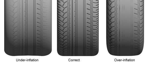
3 1. Wheel allows the wheels to roll without scuffing, dragging or slipping. Alignment Balancing Rotation

4 2. Proper alignment of both the front & rear wheels ensures, easier, longer life, reduced consumption, and less strain on steering & suspension parts. Safety, Steering, Tire, Fuel Safety, Braking, Parts, Oil Safety, Traction, Tire, Fuel


5 3. A wheel alignment restores the of the steering & suspension angles of the vehicle to properly locate the vehicle s weight on the tires and other moving parts and to facilitate steering. Geometry Dimensions Tolerances


6 4. When performing a 4 wheel alignment, wheels are adjusted first and then the front wheels are aligned to the vehicle s geometric centerline. Front Rear Steering


7 5. Alignment angles may be different on each side of a vehicle to compensate for. Road Crown Road Grade Road Surface

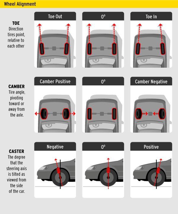
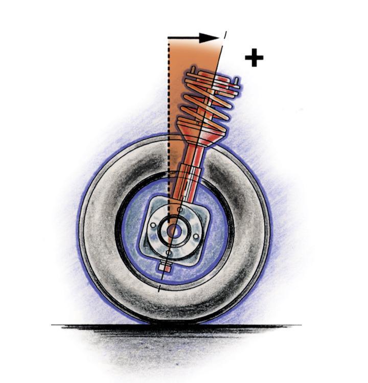
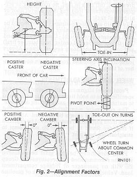
8 6. is forward or rearward tilt of the steering axis as viewed from the side of the vehicle. Caster Camber Toe


9 7. Caster provides steering. Caster is not considered a tire wear angle & is adjusted first. Accuracy Stability Balance

10 8. A vehicle will pull or drift to the side with the caster. (also called most negative) Most Least Neutral


11 9. Equal, but too much negative caster will cause a vehicle to on straight roads. Pull Drift Wander


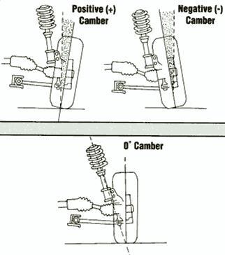
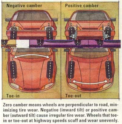
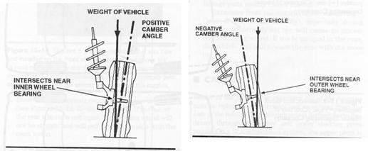
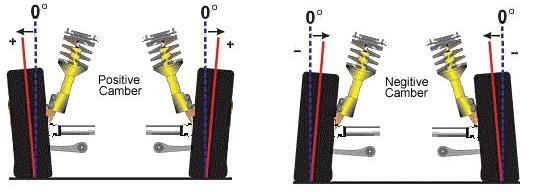
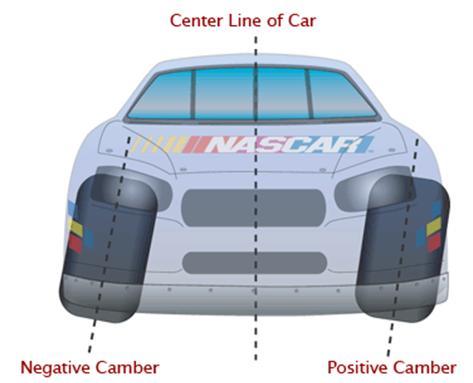
12 10. is inward or outward tilt of the tires at the top as viewed from the front of the vehicle. Caster Camber Toe


13 11. Camber compensates for, passenger & vehicle weight. Camber is a tire wear angle. Road Harshness Road Hogs Road Crown

14 12. A vehicle will pull or drift to the side with the camber. (also called most positive) Most Least Neutral
15 13. Anything that changes chassis or ride also changes camber. (adjusts on control arms) Height Strength Alignment

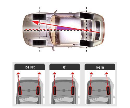
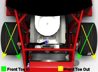
16 14. is the inward or outward pointing or aim of the tires as viewed from the top of the vehicle. Caster Camber Toe


17 15. is known as positive toe. is known as negative toe. + + Toe in, Toe out Toe out, Toe in Zero Toe, Neutral Toe

18 16. Front toe adjustment is made at the and is the adjustment to be made. Stabilizer Links, First Control Arms, First Tie Rods, Last


19 17. Improperly adjusted toe causes the steering wheel to be. It will cause dog tracking & is the most severe tire wear angle leading to feather edge or saw tooth wear patterns. Off Center Out of Round Sloppy
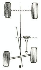
20 18. The difference of rear toe from the geometric centerline is known as. + Thrust Line or Thrust Angle Trust Back Thrust Radius
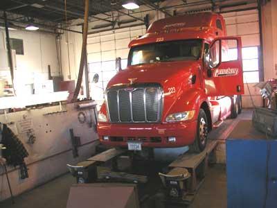
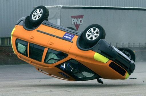
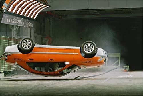
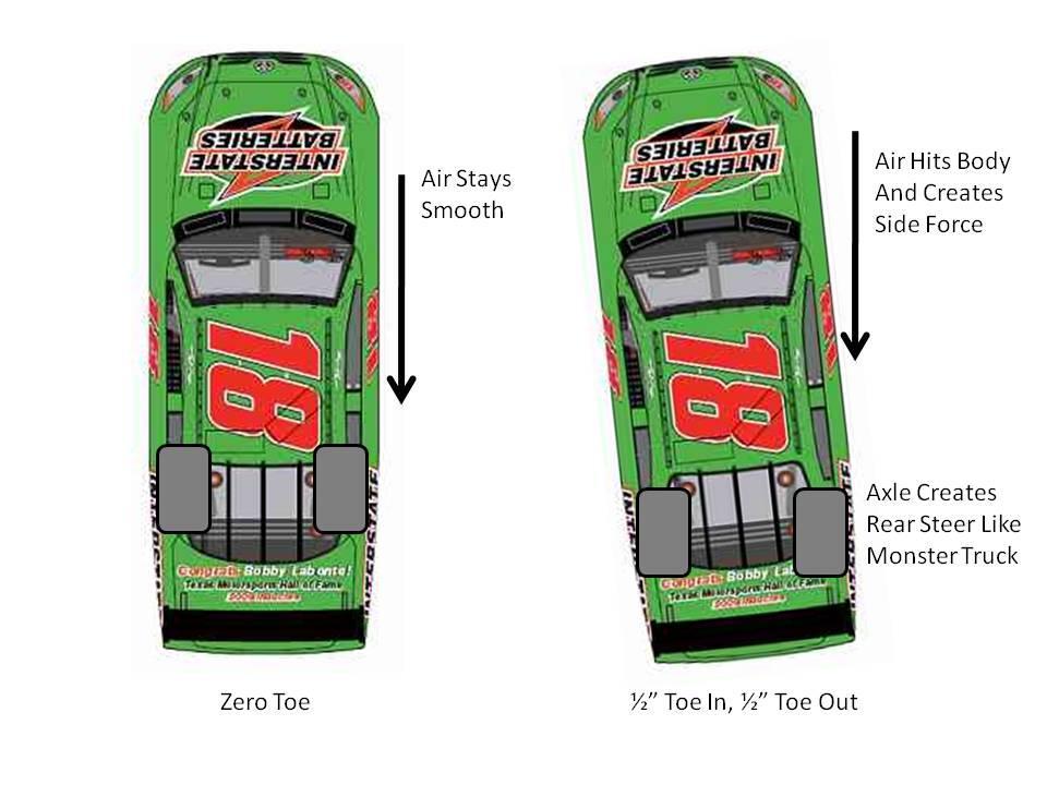
21 19. Four wheel alignment begins with adjusting the wheels to be correctly cambered and to match the geometric centerline of the vehicle to avoid an off center steering wheel & dog tracking. Explain what s going on in this picture Front Rear Training
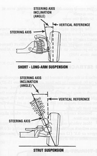
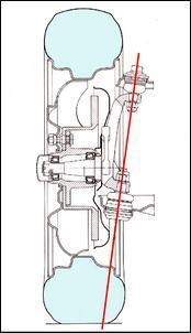
22 20. (SAI) is the angle between true vertical and a line between the steering pivots or ball joints as viewed from the front of the vehicle. Steering Axis Inclination Shortened Axial Inclination Sweet Child of Mine

23 21. SAI is an engineering angle that properly locates vehicle weight and provides to a straight ahead position with the steering wheel after a turn. SAI is not adjustable. Deviation Return Bump Steer

24 22. is a diagnostic angle. If incorrect, parts are dislocated or damaged & need replacement. Unequal SAI side to side can cause torque steer, brake pull, and bump steer. SLA Toe SAI
25 23. The sum of the camber angle added to steering axis inclination is called. This is also a diagnostic angle, that indicates bent or dislocated parts if not within specs. Induced Angle Included Angle Insane Angle

26 24. is the distance between the center of the tire and where SAI intersects the road surface. Scrub radius is not adjustable, but can cause a pull if it is unequal side to side. Vehicles with a diagonal split brake system have negative scrub radius built into the steering geometry. If one half of the brake system fails, then the vehicle will tend to pull up in a straight line. Included Angle Scrub Mop Scrub Radius
27
28 25. Turning radius is the amount of on turns, often called turning angle. It is a diagnostic angle and if incorrect, a bent steering arm or steering knuckle may be suspected. Toe In Toe Out Toe Around

29 26. During turns, the outer wheel moves through a lesser numerical angle. True or False

30 27. Turning radius is not adjustable. If incorrect,, steering arms, or knuckles are bent.

31 28. is the direction the rear axle would travel if unaffected by the front wheels.


32 29. Correct refers to a situation with all suspension and wheels in their correct location and condition and aligned to that the rear wheels follow directly behind the front wheels while driving in a straight line. All 4 wheels form a perfect rectangle & are parallel to geometric centerline. Positioning Punctuation Tracking

33 30. An offset thrust angle affects handling by pulling from the thrust line. A positive thrust angle points the rear tires to the right. A negative thrust angle points the rear tires to the left. Away Toward Left of

34 31. Every vehicle is built to operate a designed height. Also called trim, chassis or ride height. Curb Rim Roof
35

36 32. Always begin alignment with a test to verify customer complaint & note any problems. Note: Your road test should simulate customer driving and be used to verify the complaint or concern Scope Road Litmus


37 33. Pre alignment inspection of the, steering, suspension, tire inflation & wear, wheel bearing adjustment, abnormal vehicle loads, ride height, and steering wheel play are important. Roof Brakes PCM


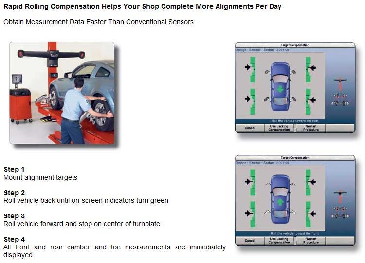
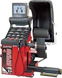
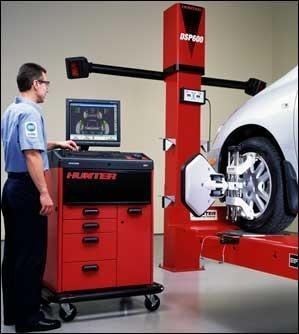
38 34. An alignment with front turn plates and rear slip plates allow for 4 wheel adjustment. Rack Bay Stall Note: Turn Plate Marked in Degrees used to Diagnose Toe out on Turns

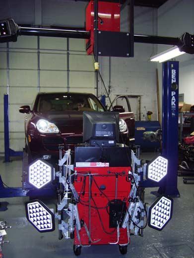
39 35. Alignment heads (targets) are attached to the four wheels and are then for runout. (Rolling Compensation vs. Raised & Rotated) Compensated Complicated Communicated
40

41 36. Rear is adjusted first followed by rear. This establishes a zero thrust angle. Camber, Toe Caster, Camber Caster, SAI

42 37. After adjusting the rear of the vehicle, front caster, camber, & lastly front wheel are adjusted in that order, although the caster & camber adjustment may take place simultaneously. Camber Toe SAI
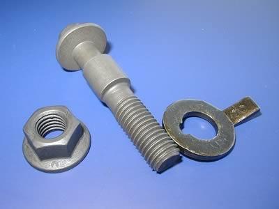
43 38. Most vehicles are set with a caster angle & near zero or a slightly positive camber. Positive Zero Negative


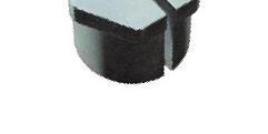
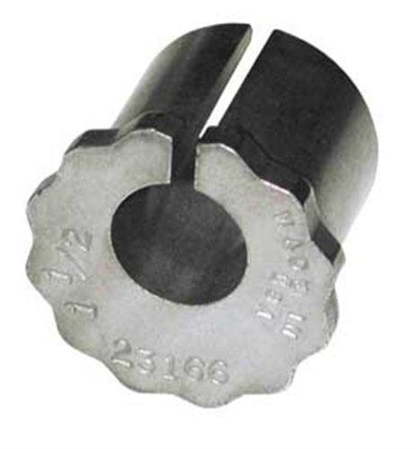
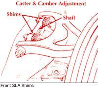
44 39. Caster & camber may be adjusted with, bolts & cams, holes in the frame under the control arm, a rotating, shortening or lengthening a strut rod that holds the lower control arm, or by repositioning the MacPherson strut top or bottom. Shims, Eccentric, Slotted, Ball Joint Shims, Washers, Jagged, Tie Rod Joints Shims, Strut Rods, Slotted, Strut Joints
45


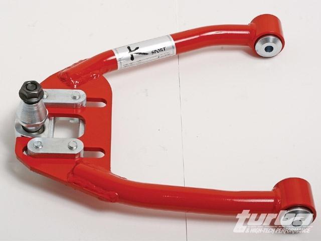
46 40. If OEM makes no allowance for caster or camber adjustment, aftermarket are often readily available from parts stores to make the angles adjustable. Kits Zits Kites


47 41. Sagging springs or overloading of the rear suspension causes camber on the rear. Positive Negative Neutral

48 42. If the rear axle pulls to the right, the vehicle will drift to the. (thrust angle concept) Right Left Center


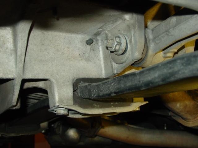
49 43. A shim between the rear spindle & spindle mounting can adjust/correct both rear camber and rear toe. Inclined Plane Full Contact Special NAPA


50 44. Front is the last angle to be adjusted. This is done with the steering wheel. Caster Camber Toe Off Center Removed Centered

51 45. Some manufacturers recommend a steering wheel gauge to ensure the wheel is centered. Angle Dangle Rangle
52 46. On FWD vehicles the front wheels tend to toe under power & the rears toe in response to rolling resistance & suspension compliance. Zero running toe is the goal.

53 47. On RWD vehicles, the front wheels tend to toe while the rear wheels on an independent suspension tend to toe in as they push the vehicle ahead. Zero running toe is the goal.

54 48. Improperly cambered or toed rear wheels can affect steering as well as ABS. True or False
55 49. A thrust line or thrust angle that is off center to the right will cause a pull to the. Right Left Rear


56 50. Front wheels aligned to a rear thrust line, centers the steering wheel but results in tracking. Note: Rear paws not directly behind front paws. Elephant Dog Deer

57 51., is a condition when one wheel on an axle is set behind the other. It will cause an off center steering wheel, just like unequal toe. It can be caused by a misaligned front cradle. Set back Give back Take back
 can scrub feet sideways")

58 52. Toe misalignment of only 1/8 (.125, 3mm, ¼ degree) can scrub feet sideways every mile! That s why toe is considered to be the most severe tire wearing angle!

59 53. The direction of feather edge or saw tooth tire wear indicates the toe problem. True or False Toe Wear Camber Wear
60
61
62
63
64
65
66
67
68
69
70
71
72
73
74
75
76
77
78
79
80
81
82
83
84

85
86
87
88


89 Magnetic Caster Camber Gauges

90
91
92
93
94
95
96
97
98
99
100
101

102
103
104 Camber Caster Inward Outward Tilt of the Tire As Viewed from the Front of the Vehicle Forward Rearward Tilt of the Steering Axis As Viewed from the Side of the Vehicle

105 Camber Caster
106 Toe Angle

107 Toe Angle Inward Outward Pointing of the Tires As viewed from the Top of the Vehicle
108
109
110
111
112
113
114
115
Why do cars need Alignment
 Why do cars need Alignment The main purpose of wheel alignment is to make the tires roll without Scuffing, slipping, or dragging under all operating conditions. Caster Camber Toe Steering axis inclination
Camber Angle. Wheel Alignment. Camber Split. Caster Angle. Caster and Ride Height. Toe Angle. AUMT Wheel Alignment
 AUMT 1316 - Wheel Alignment 11/15/11 Camber Angle Wheel Alignment Donald Jones Brookhaven College Camber Split Camber is the amount that the centerline of the wheel tilts away from true vertical when viewed
2004 SUSPENSION. Wheel Alignment - Corvette. Caster Cross +/ / Fastener Tightening Specifications Specification Application
 2004 SUSPENSION Wheel Alignment - Corvette SPECIFICATIONS WHEEL ALIGNMENT SPECIFICATIONS Wheel Alignment Specifications Camber Cross Caster Cross Suspension Camber Tolerance Caster Tolerance FE1 & FE3
Wheel Alignment Fundamentals
 CHAPTER 67 Wheel Alignment Fundamentals OBJECTIVES Upon completion of this chapter, you should be able to: Describe each wheel alignment angle. Tell which alignment angles cause wear or pull. KEY TERMS
GENERAL INFORMATION. Wheel Alignment Theory & Operation
 Fig. 1: Checking Steering Linkage GENERAL INFORMATION Wheel Alignment Theory & Operation ADJUSTMENTS NOTE: This article is intended for general information purposes only. This information may not apply
Basic Wheel Alignment Techniques
 Basic Wheel Alignment Techniques MASTERING THE BASICS: Modern steering and suspension systems are great examples of solid geometry at work. Wheel alignment integrates all the factors of steering and suspension
Suspension and Steering Alignment
 Suspension and Steering Alignment Matthew Whitten Brookhaven College Alignment Components Ride height Caster Camber Included angle Scrub radius Thrust angle Toe Turning radius Toe out on turns Steering
Wheel Alignment And Diagnostic Angles (STE04)
") Module 1 Wheel Alignments Wheel Alignment And Diagnostic Angles (STE04) Wheel Alignments o Conditions Requiring An Alignment o Conditions Requiring An Alignment (cont d) o Why We Do Checks And Alignments
Module 1 Wheel Alignments Wheel Alignment And Diagnostic Angles (STE04) Wheel Alignments o Conditions Requiring An Alignment o Conditions Requiring An Alignment (cont d) o Why We Do Checks And Alignments
BASIC WHEEL ALIGNMENT
 BASIC WHEEL ALIGNMENT You have got to know all the angles. Correct wheel alignment plays a huge part in a customer s positive driving experience. Having it dialed in correctly is essential to proper vehicle
Typical mounting of a dial indicator for a radial check. Moog Automotive, Inc.
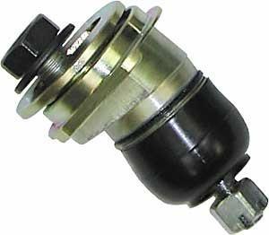
 Inspect / Service / Test / Replace To find out if the ball joint is loose beyond manufacturer's specifications, use an accurate measuring device. Most load carrying ball joints have a wear limit of 0.060"
The WHAT and WHY of. Toe Caster - Camber Kingpin Inclination - Thrust Angle Steering Angle Wheel setback
 The WHAT and WHY of Toe Caster - Camber Kingpin Inclination - Thrust Angle Steering Angle Wheel setback WHEEL ALIGNMENT SIMPLIFIED Wheel alignment is often considered complicated and hard to understand
WHEEL ALIGNMENT SPECIFICATIONS & PROCEDURES
 WHEEL ALIGNMENT SPECIFICATIONS & PROCEDURES 1988 Jeep Cherokee 1988 Wheel Alignment INTRODUCTION PRE-ALIGNMENT VEHICLE CHECKS Prior to making wheel alignment adjustments, check and adjust the following
INTRO/APPLICATIONS PARTS TOOLS ACCESSORIES BRAKE & CV SPC GEAR & INDEXES APPLICATIONS PARTS
 TABLE OF CONTENTS INTRO/.................. 2-39 How to Use the Sourcebook......................................2 How to Sell Alignment...........................................2 Training Resources..............................................3
Wheel Alignment Basics Explained: Shimmed Control Arms
 Wheel Alignment Basics Explained: Shimmed Control Arms By Joe Fisher This brief article is not meant to teach someone how to align the front steering/suspension but to explain the three basic specifications
Wheel Alignment Defined
 Wheel Alignment Defined While it's often referred to simply as an "alignment" or "wheel alignment," it's really complex suspension angles that are being measured and a variety of suspension components
Wheel Alignment Service
 CHAPTER 68 Wheel Alignment Service OBJECTIVES Upon completion of this chapter, you should be able to: Perform a prealignment inspection of the steering and suspension. Describe how to adjust caster, camber,
1. SPECIFICATIONS 2. WHEEL ALIGNMENT Front Suspension. (gas type) Rear Suspension. (gas type)
 Rear Suspension. (gas type)") 441101 053 1. SPECIFICATIONS Front Suspension Rear Suspension Description Suspension type Spring type Shock absorber type Stabilizer bar type Suspension type Spring type Shock absorber type Stabilizer
441101 053 1. SPECIFICATIONS Front Suspension Rear Suspension Description Suspension type Spring type Shock absorber type Stabilizer bar type Suspension type Spring type Shock absorber type Stabilizer
AXLE ALIGNMENT ZF (40 FT)
") SECTION 04-000.10 04-000.10/ 1 2010DE06 GENERAL CONDITIONS See Figures 1 and 2 for the geometry of the frontand rear axles. Figure 3 represents the axis system of a Nova LFS 40-ft bus. Before performing
SECTION 04-000.10 04-000.10/ 1 2010DE06 GENERAL CONDITIONS See Figures 1 and 2 for the geometry of the frontand rear axles. Figure 3 represents the axis system of a Nova LFS 40-ft bus. Before performing
SUSPENSION 2-1 SUSPENSION TABLE OF CONTENTS
 XJ SUSPENSION 2-1 SUSPENSION TABLE OF CONTENTS page ALIGNMENT... 1 FRONT SUSPENSION... 7 page REAR SUSPENSION... 16 ALIGNMENT TABLE OF CONTENTS page AND WHEEL ALIGNMENT...1 DIAGNOSIS AND TESTING SUSPENSION
Customer Engagement - Execution Playbook Module 1 WHEEL ALIGNMENTS ALIGNMENTS
 Customer Engagement - Execution Playbook Module 1 WHEEL ALIGNMENTS -------------------------- ALIGNMENTS 101 ------------------------------ While a wheel alignment is often referred to simply as an alignment,
SECTION 3A WHEEL ALIGNMENT
 SECTION 3A WHEEL ALIGNMENT NOTICE: All wheel alignment fasteners are important attaching parts in that they could affect the performance of vital components and systems, and/or could result in major repair
1. SPECIFICATIONS 2. WHEEL ALIGNMENT
 441101 083 1. SPECIFICATIONS Front Suspension Rear Suspension Description Suspension type Spring type Shock absorber type Stabilizer bar type Suspension type Spring type Shock absorber type Stabilizer
TRUCK AND BUS TYRE I TECHNICAL MANUAL MAINTENANCE AND CARE
 TRUCK AND BUS TYRE I TECHNICAL MANUAL MAINTENANCE AND CARE About tyre inflation Truck alignment and tyre wear Tyre damage TECHNICAL INFORMATION MAINTENANCE AND CARE About tyre inflation ONE OF THE MOST
Fiat - Argentina - Wheel Aligner / Headlamp Aimer #16435
 2017 Fiat - Argentina - Wheel Aligner / Headlamp Aimer #16435 Wheel Aligner / Headlamp Aimer Operation & Maintenance Manual Overview Fori Automation Version 1.2 4/21/2017 TABLE OF CONTENTS Section 1.0
Axles & Differentials
 ATASA 5 th Study Guide Chapter 39 Pages 1138 1172 60 Points Please Read The Summary Before We Begin Keeping in mind the Career Cluster of Transportation, Distribution & Logistics Ask yourself: What TDL
Chapter-3. Wheel Alignment Wheel Kinematics and Compliance Steering Performance Criteria for Handling
 Chapter-3 Wheel Alignment Wheel Kinematics and Compliance Steering Performance Criteria for Handling Components of Suspension Linkage Bearings, Bushings Springs Dampers Wheel Geometry Wheel Geometry Wheel
Wheel Alignment - Basics
 Service Training Self Study Program 860103 Wheel Alignment - Basics Volkswagen Group of America, Inc. Volkswagen Academy Printed in U.S.A. Printed 2/2012 Course Number 860103 2012 Volkswagen Group of America,
How to Set the Alignment on Ford Mustangs
 How to Set the Alignment on 1967-1973 Ford Mustangs Let's Get This Straight - Mustang Monthly Magazine Christopher Campbell Technical Editor March 25, 2015 Frontend alignment is one of the most basic adjustments
DIAGNOSIS AND TESTING
 DIAGNOSIS AND TESTING SUSPENSION AND STEERING SYSTEM 2007 SUSPENSION Suspension - Nitro CONDITION POSSIBLE CAUSES CORRECTION FRONT END NOISE 1. Loose or worn wheel bearings. 1. Replace wheel bearings.
Fundamentals of Steering Systems ME5670
 Fundamentals of Steering Systems ME5670 Class timing Monday: 14:30 Hrs 16:00 Hrs Thursday: 16:30 Hrs 17:30 Hrs Lecture 3 Thomas Gillespie, Fundamentals of Vehicle Dynamics, SAE, 1992. http://www.me.utexas.edu/~longoria/vsdc/clog.html
FRONT AXLE GROUP 11A CONTENTS 11A-0. SECTION 0 GENERAL Removal 3 SECTION 1 FRONT AXLE HUB 1
 11A-0 GROUP 11A FRONT AXLE CONTENTS SECTION 0 GENERAL 1 1-1 Removal 3 SECTION 1 FRONT AXLE HUB 1 1-2 Inspection 3 1-3 Installation 4 1. Removal and Installation 1 1-1 Removal 1 SECTION 3 WHEEL ALIGNMENT
Vehicle Level Steering and Suspension Alignment Service and Repair Wheel Alignment. Wheel Alignment
 Page 1 of 7 2002 Dodge Truck Caravan FWD V6-3.3L VIN R Vehicle Level Steering and Suspension Alignment Service and Repair Wheel Alignment Wheel Alignment PRE-WHEEL ALIGNMENT INSPECTION Before any attempt
1 of 12 8/25/2017, 4:29 PM
 1 of 12 8/25/2017, 4:29 PM STANDARD PROCEDURE - WHEEL ALIGNMENT PRE-WHEEL ALIGNMENT INSPECTION Before any attempt is made to change or correct the wheel alignment, the following inspection and necessary
WHEEL ALIGNMENT PROCEDURES
 WHEEL ALIGNMENT PROCEDURES PRE-ALIGNMENT CHECKS Ensure steering wheel is centered and front wheels are in straight-ahead position (to correct, shorten one tie rod adjusting sleeve and lengthen the opposite
Sequoia power steering rack service Match-mounting wheels and tires Oxygen sensor circuit diagnosis
 In this issue: Sequoia power steering rack service Match-mounting wheels and tires Oxygen sensor circuit diagnosis PHASE MATCHING Often referred to as match mounting, phase matching involves mounting the
SUSPENSION 2-1 SUSPENSION CONTENTS
 TJ SUSPENSION 2-1 SUSPENSION CONTENTS page ALIGNMENT... 1 FRONT SUSPENSION... 5 page REAR SUSPENSION... 12 ALIGNMENT INDEX page GENERAL INFORMATION WHEEL ALIGNMENT... 1 DIAGNOSIS AND TESTING SUSPENSION
SUSPENSION 2-1 SUSPENSION CONTENTS
 TJ SUSPENSION 2-1 SUSPENSION CONTENTS page ALIGNMENT... 1 FRONT SUSPENSION... 6 page REAR SUSPENSION... 13 ALIGNMENT INDEX page DESCRIPTION AND OPERATION WHEEL ALIGNMENT... 1 DIAGNOSIS AND TESTING SUSPENSION
2. MEASURE VEHICLE HEIGHT. (b) Measure the vehicle height. Measurement points: C: Ground clearance of front wheel center
 Measure the vehicle height. Measurement points: C: Ground clearance of front wheel center") ADJUSTMENT If the wheel alignment has been adjusted, and if suspension or underbody components have been removed/installed or replaced, be sure to perform the following initialization procedure in order
ADJUSTMENT If the wheel alignment has been adjusted, and if suspension or underbody components have been removed/installed or replaced, be sure to perform the following initialization procedure in order
ALIGNING A 2007 CADILLAC CTS-V
 ALIGNING A 2007 CADILLAC CTS-V I ll describe a four-wheel alignment of a 2007 Cadillac CTS-V in this document using homemade alignment tools. I described the tools in a previous document. The alignment
AER Automotive Steering and Suspension
 2013 NATEF JOB TASKS COMPLETION REQUIREMENT: P1-95% P2-80% P3-50% Student Name: DETAILED COURSE CONTENT AUTOMOTIVE SUSPENSION AND STEERING TECHNICIAN DEMONSTRATE PROFICIENCY IN SUSPENSION AND STEERING
MM Caster/Camber Plates, (MMCC7989)
") 3430 Sacramento Dr., Unit D San Luis Obispo, CA 93401 Telephone: 805/544-8748 Fax: 805/544-8645 www.maximummotorsports.com MM Caster/Camber Plates, 1979-89 (MMCC7989) IMPORTANT: The bearing used in our
3430 Sacramento Dr., Unit D San Luis Obispo, CA 93401 Telephone: 805/544-8748 Fax: 805/544-8645 www.maximummotorsports.com MM Caster/Camber Plates, 1979-89 (MMCC7989) IMPORTANT: The bearing used in our
SU01 Independent, Strut
 Uniform Procedures For Collision Repair SU01 Independent, Strut 1. Description This procedure describes the diagnosis, repair, and inspection of an independent, strut-type suspension system. 2. Purpose
SUSPENSION 2-1 SUSPENSION CONTENTS
 ZJ SUSPENSION 2-1 SUSPENSION CONTENTS page ALIGNMENT... 1 FRONT SUSPENSION... 6 page REAR SUSPENSION... 14 ALIGNMENT INDEX page GENERAL INFORMATION WHEEL ALIGNMENT... 1 DIAGNOSIS AND TESTING SUSPENSION
SUSPENSION 2-1 SUSPENSION TABLE OF CONTENTS
 DN SUSPENSION 2-1 SUSPENSION TABLE OF CONTENTS page ALIGNMENT... 1 FRONT SUSPENSION - 4x2... 6 page FRONT SUSPENSION - 4x4... 14 REAR SUSPENSION... 23 ALIGNMENT TABLE OF CONTENTS page AND OPERATION WHEEL
2011 MKS Workshop Manual. SECTION : Suspension System - General Information DESCRIPTION AND OPERATION Procedure revision date: 05/25/2010
 SECTION 204-00: Suspension System - General Information 2011 MKS Workshop Manual DESCRIPTION AND OPERATION Procedure revision date: 05/25/2010 Wheel Alignment Angles Camber Negative and Positive Camber
2013 NATEF Task Area A-4 Suspension, Steering, Alignment7-2013
 2013 NATEF Task Area A-4 Suspension, Steering, Alignment7-2013 A. Steering System Diagnosis & Repair B. Suspension System Diagnosis & Repair C. Wheel Alignment Diagnosis & Adjustment D. Wheel & Tire Diagnosis
2. Remove front wheels.
 Read all instructions before beginning work. Following instructions in the proper sequence will ensure the best and easiest installation. Thank you for purchasing Maximum Motorsports Caster/Camber Plates.
WHEEL ALIGNMENT PROCEDURES
 Page 1 of 8 WHEEL ALIGNMENT PROCEDURES TURNING ANGLE Turn steering wheel fully right and then left, and observe turning radius on both wheels. If turning radius is incorrect, inspect and replace any damaged
SUSPENSION 2-1 SUSPENSION CONTENTS
 WJ SUSPENSION 2-1 SUSPENSION CONTENTS page ALIGNMENT... 1 FRONT SUSPENSION... 4 page REAR SUSPENSION... 15 ALIGNMENT INDEX page AND WHEEL ALIGNMENT... 1 SERVICE PROCEDURES PRE-ALIGNMENT... 2 AND WHEEL
INSTRUCTIONS FOR STRUT FRONT, 4-LINK REAR, ROADSTER CHASSIS
 #917406 Page 1 of 5 7406 INSTRUCTIONS FOR STRUT FRONT, 4-LINK REAR, ROADSTER CHASSIS ITEM QTY SIZE/PART NO. TUBE CODE DESCRIPTION 1 1 4215 Front frame rail strut 1 5/8 (pair) 2 1 4236 Roadster firewall
2010 Prince Edward Island Department of Education and Early Childhood Development P.O. Box 2000, Charlottetown Prince Edward Island Canada, C1A 7N8
 2010 Prince Edward Island Department of Education and Early Childhood Development P.O. Box 2000, Charlottetown Prince Edward Island Canada, C1A 7N8 Tel. (902) 368-4600 Fax. (902) 368-4622 http://www.gov.pe.ca/eecd/
FRONT SUSPENSION GROUP CONTENTS GENERAL INFORMATION FASTENER TIGHTENING SPECIFICATIONS GENERAL SPECIFICATIONS...
 33-1 GROUP 33 FRONT SUSPENSION CONTENTS GENERAL INFORMATION 33-2 FASTENER TIGHTENING SPECIFICATIONS 33-2 GENERAL SPECIFICATIONS 33-3 SERVICE SPECIFICATIONS 33-3 DIAGNOSIS 33-4 INTRODUCTION TO DIAGNOSIS
UNIBODY/FRAME/WHEEL ALIGNMENT II ABCT 2212
 UNIBODY/FRAME/WHEEL ALIGNMENT II ABCT 2212 A. Course Description Credits: 6.00 Lecture Hours/Week: 1.00 Lab Hours/Week: 5.00 OJT Hours/Week: 0 Prerequisites: None Corequisites: None MnTC Goals: None This
TRADE OF HEAVY VEHICLE MECHANIC
 TRADE OF HEAVY VEHICLE MECHANIC PHASE 2 Module 8 Steering and Suspension Systems UNIT: 2 Table of Contents 1.0 Learning Outcome... 1 1.1 Key Learning Points... 1 2.0 Health and Safety... 3 3.0 The Function
Wheel Alignment on Heavy-Duty Trucks
 What you need to know about Wheel Alignment on Heavy-Duty Trucks January 2017 Price: $19.99 Contents What is Proper Wheel Alignment?................................. 3 Alignment Angles and Effects...................................
Hemet High School NATEF SUSPENSION AND STEERING CHECKLIST. Name Date Period
 Hemet High School NATEF SUSPENSION AND STEERING CHECKLIST Name Period For every task in Suspension and Steering, the following safety requirement must be strictly enforced: Comply with personal and environmental
1. General Description
 General Description 1. General Description A: SPECIFICATION Front Rear Model Wheel arch height (Tolerance: +12 mm 24 mm ( +0.47 in 0.94 in)) mm (in) 376 (14.8) Camber (Tolerance: 0 45 Differences between
STEERING SYSTEM Introduction
 STEERING SYSTEM Introduction The steering makes it possible to change direction. The steering must be reliable and safe; there must not be too much play in the steering. It must be possible to steer accurately.
Installation Procedure GR40 S197 SLA Front Suspension System (Does not include Aluminum Spindle and Hub Instructions)
") Installation Procedure GR40 S197 SLA Front Suspension System (Does not include Aluminum Spindle and Hub Instructions) Please take the time and read these instructions first! The GR40 S197 system is designed
Installation Procedure GR40 S197 SLA Front Suspension System (Does not include Aluminum Spindle and Hub Instructions) Please take the time and read these instructions first! The GR40 S197 system is designed
GROUP 33A 33A-1 CONTENTS GENERAL DESCRIPTION... 33A-2 FRONT SUSPENSION DIAGNOSIS. 33A-3 LOWER ARM... 33A-13 SPECIAL TOOLS... 33A-5
 33A-1 GROUP 33A CONTENTS GENERAL DESCRIPTION 33A-2 DIAGNOSIS 33A-3 INTRODUCTION TO FRONT SUSPENSION DIAGNOSIS 33A-3 DIAGNOSIS TROUBLESHOOTING STRATEGY 33A-3 SYMPTOM CHART 33A-3 SYMPTOM PROCEDURES 33A-3
FRONT SUSPENSION GROUP 33A 33A-1 CONTENTS GENERAL DESCRIPTION... 33A-2 FRONT SUSPENSION DIAGNOSIS. 33A-3 LOWER ARM... 33A-13 SPECIAL TOOLS...
 33A-1 GROUP 33A FRONT SUSPENSION CONTENTS GENERAL DESCRIPTION......... 33A-2 DIAGNOSIS. 33A-3 INTRODUCTION TO DIAGNOSIS........................ 33A-3 DIAGNOSIS TROUBLESHOOTING STRATEGY...... 33A-3 SYMPTOM
1940 Hudson SERVICING THE FRONT SUSPENSION SYSTEM
 1940 Hudson SERVICING THE FRONT SUSPENSION SYSTEM Source of this material is from 1940 Series, Issue 3, November-December Hudson Service Magazine SERVICING THE FRONT SUSPENSION SYSTEM No set rule can be
INSTRUCTIONS FOR STRUT FRONT, 4-LINK REAR, 1 5/8 FRAME, FULL SIZE, 4130 ELIMINATOR CHASSIS
 #917230 Page 1 of 6 7230 INSTRUCTIONS FOR STRUT FRONT, 4-LINK REAR, 1 5/8 FRAME, FULL SIZE, 4130 ELIMINATOR CHASSIS ITEM QTY SIZE/PART NO. TUBE CODE DESCRIPTION 1 2 4350 Cage Side 2 2 4351 Forward strut
7256 INSTRUCTIONS FOR ELIMINATOR II A-ARM FRONT, 4-LINK REAR, MILD STEEL, INTERMEDIATE, SERIES CHASSIS
 #917256 Page 1 of 7 7256 INSTRUCTIONS FOR ELIMINATOR II A-ARM FRONT, 4-LINK REAR, MILD STEEL, INTERMEDIATE, SERIES CHASSIS ITEM QTY SIZE/PART NO. TUBE CODE DESCRIPTION 1 2 4138 Cage Side 2 2 4208 Forward
ELECTRONIC CHASSIS ALIGNMENT
 SUSPENSION Steering and Wheel Alignment - Repair Instructions - X6 ELECTRONIC CHASSIS ALIGNMENT 32... OVERVIEW OF STEERING Fig. 1: Overview Of Steering 32... OVERVIEW OF ACTIVE FRONT STEERING Fig. 2: Overview
7211 A-ARM FRONT, 4-LINK, 3 X 2 FRAME, INTERMEDIATE, ELIMINATOR CHASSIS ITEM QTY SIZE/PART NO. TUBE CODE DESCRIPTION
 #917211 Page 1 of 6 7211 A-ARM FRONT, 4-LINK, 3 X 2 FRAME, INTERMEDIATE, ELIMINATOR CHASSIS ITEM QTY SIZE/PART NO. TUBE CODE DESCRIPTION 1 2 4138 Cage Side 2 2 4208 Forward strut 3 1 4038 Main Hoop 4 1
JHM Butt & Co Ltd. Station Yard, Bawtry, Doncaster, South Yorks DN10 6QD Tel:
 JHM Butt & Co Ltd Station Yard, Bawtry, Doncaster, South Yorks DN10 6QD Tel: 01302 710868 Email: info@buttsofbawtry.com www.buttsofbawtry.com Our Tracking Guage Single Steer Rear Flag - Car Turn Table
ALIGNMENT AND ROAD CROWN
 Classification: Reference: Date: ST08-001 NTB08-097 October 9, 2008 ALIGNMENT AND ROAD CROWN APPLIED VEHICLES: All Nissan - except GT-R SERVICE INFORMATION Customers may report that their vehicle pulls
Torque steer effects resulting from tyre aligning torque Effect of kinematics and elastokinematics
 P refa c e Tyres of suspension and drive 1.1 General characteristics of wheel suspensions 1.2 Independent wheel suspensions- general 1.2.1 Requirements 1.2.2 Double wishbone suspensions 1.2.3 McPherson
FRONT SUSPENSION GROUP CONTENTS GENERAL INFORMATION ON-VEHICLE SERVICE FASTENER TIGHTENING SPECIFICATIONS...
 33-1 GROUP 33 FRONT SUSPENSION CONTENTS GENERAL INFORMATION 33-2 FASTENER TIGHTENING SPECIFICATIONS 33-2 GENERAL SPECIFICATIONS 33-3 SERVICE SPECIFICATIONS 33-3 LUBRICANTS 33-3 DIAGNOSIS 33-4 INTRODUCTION
7333 INSTRUCTIONS FOR MILD STEEL A-ARM AVENGER CHASSIS MUSTANG
 #917333 Page 1 of 5 7333 INSTRUCTIONS FOR MILD STEEL A-ARM AVENGER CHASSIS 1994-2004 MUSTANG ITEM QTY PART NO/SIZE TUBE CODE DESCRIPTION 1 1 4080 Main hoop 2 1 pr 4180 Cage side (driver & passenger side)
SUSPENSION 2-1 SUSPENSION CONTENTS
 DN SUSPENSION 2-1 SUSPENSION CONTENTS page ALIGNMENT... 1 FRONT SUSPENSION... 5 page REAR SUSPENSION... 13 ALIGNMENT INDEX page GENERAL INFORMATION WHEEL ALIGNMENT... 1 DIAGNOSIS AND TESTING PRE-ALIGNMENT
AlterKtion. Installation manual and information booklet CAUTION! PLEASE READ THIS ENTIRE BOOKLET BEFORE PROCEEDING WITH INSTALLATION
 AlterKtion Installation manual and information booklet CAUTION! PLEASE READ THIS ENTIRE BOOKLET BEFORE PROCEEDING WITH INSTALLATION Assembling the Components --------------------------------------------------------------------2
geoliner 780 WHeel aligner
 geoliner 780 WHEEL ALIGNER Maximize Profits with the geoliner TM 780 The geoliner TM 780 is the fastest, most accurate aligner in the industry. Thanks to its DigiSmart technology, the geoliner TM 780 s
7260 INSTRUCTIONS FOR ELIMINATOR II STRUT FRONT, 4-LINK REAR, MILD STEEL, FULL SIZE, SERIES CHASSIS
 #917260 Page 1 of 6 7260 INSTRUCTIONS FOR ELIMINATOR II STRUT FRONT, 4-LINK REAR, MILD STEEL, FULL SIZE, SERIES CHASSIS ITEM QTY SIZE/PART NO. TUBE CODE DESCRIPTION 1 2 4139 Cage Side 2 2 4250 Forward
Global West Suspension 655 South Lincoln Ave San Bernardino Ca Phone Fax Web address globalwest.
 Global West Suspension 655 South Lincoln Ave San Bernardino Ca. 92408 Phone 877-470-2975 Fax 909-890-0703 Web address globalwest.net Mustang coilover instruction sheets for 64-66 Kit includes the following
INDEX GENERAL. Page Connecting Rod 2M-3 Front Wheel Alignment 2M-4 Front Wheel Shimmy 2M-5 General 2M-1
 INDEX Page Connecting Rod 2M-3 Front Wheel Alignment 2M-4 Front Wheel Shimmy 2M-5 General 2M-1 Pago Specifications 21-8 Steering Damper 2M-3 Steering Wheel Spoke Alignment 2M-5 Tie Rod 2M-3 GENERAL The
Hunter Alignment. The following courses are available. Read descriptions of each on the pages that follow.
 Hunter Alignment Two to five day courses for both entry-level and seasoned technicians who need wheel alignment training. Hunter Alignment courses are presented across the country. The following courses
VERNON COLLEGE SYLLABUS. DIVISION: Information & Industrial Technology DATE: Fall COURSE NUMBER AND TITLE: AUMT 1416 Suspension and Steering
 VERNON COLLEGE SYLLABUS DIVISION: Information & Industrial Technology DATE: Fall 2010 CREDIT HRS: 4 HRS/WK LEC: 3 HRS/WK LAB: 3 LEC/LAB: 6 I. CATALOG DESCRIPTION: Theory and operation of automotive suspension
US Patent You will find many features that set our Caster/Camber Plates apart from the rest.
 3430 Sacramento Dr., Unit D San Luis Obispo, CA 93401 Telephone: 805/544-8748 Fax: 805/544-8645 www.maximummotorsports.com US Patent 6485223 Read all instructions before beginning work. Following instructions
FRONT SUSPENSION AND STEERING LINKAGE
 A FRONT SUSPENSION AND STEERING LINKAGE CONTENTS GROUP 2 Page LOWER BALL JOINTS 12 LOWER CONTROL ARM AND SHAFT... 9 LOWER CONTROL ARM STRUT 12 PRE-ALIGNMENT INSPECTION Height Adjustment., 4 RUBBER ISOLATED
Minimising Bump Steer in the TR
 Minimising Bump Steer in the TR Bump Steer is when your wheels steer themselves without input from the steering wheel. The undesirable steering is caused by bumps in the road interacting with improper
This file is available for free download at
 This file is available for free download at http://www.iluvmyrx7.com This file is fully text-searchable select Edit and Find and type in what you re looking for. This file is intended more for online viewing
SUMMARY OF STANDARD K&C TESTS AND REPORTED RESULTS
 Description of K&C Tests SUMMARY OF STANDARD K&C TESTS AND REPORTED RESULTS The Morse Measurements K&C test facility is the first of its kind to be independently operated and made publicly available in
FRONT SUSPENSION GROUP CONTENTS GENERAL INFORMATION SPECIFICATIONS STRUT ASSEMBLY FRONT SUSPENSION DIAGNOSIS.
 33-1 GROUP 33 FRONT SUSPENSION CONTENTS GENERAL INFORMATION 33-2 SPECIFICATIONS 33-3 FASTENER TIGHTENING SPECIFICATIONS 33-3 GENERAL SPECIFICATIONS 33-3 SERVICE SPECIFICATIONS 33-3 LUBRICANT 33-3 DIAGNOSIS
SU11 Independant, SLA
 Uniform Procedures For Collision Repair UPCR SU11 Independant, SLA 1. Description This procedure describes the diagnosis, repair, and inspection of an independent, short-arm, long-arm (SLA) suspension
MM Adjustable IRS Tie-Rod (MMIRSTR-2)
") 3430 Sacramento Dr., Unit D San Luis Obispo, CA 93401 Telephone: 805/544-8748 Fax: 805/544-8645 www.maximummotorsports.com MM Adjustable IRS Tie-Rod (MMIRSTR-2) Sample Bumpsteer Curve: Read all instructions
3430 Sacramento Dr., Unit D San Luis Obispo, CA 93401 Telephone: 805/544-8748 Fax: 805/544-8645 www.maximummotorsports.com MM Adjustable IRS Tie-Rod (MMIRSTR-2) Sample Bumpsteer Curve: Read all instructions
Chrysler A-Body Tubular A-Arms Installation Instructions A-ARM INSTALLATION
 1967-1976 Dodge Demon 1112 67-72 Chrysler A-Body Tubular A-Arms Installation Instructions Thank you for your purchase of this Hotchkis Performance product. Your A-Arm set was designed with the performance
INSTALLATION GUIDE Bolt-On Drag-Race Strut Clip Chevy II
 INSTALLATION GUIDE 7702 Bolt-On Drag-Race Strut Clip 1962-67 Chevy II Description: STRUT CLIP 4130 BOLT ON 62-67 CHEVY II, INCLUDES 4130 ROUND TUBE FRAME CLIP, DOUBLE-ADJUSTABLE STRUTS, ADJUSTABLE-HEIGHT
Independent Front Suspension
 Independent Front Suspension Technical Training Contents Why Independent? Tuthill Models Features and Benefits Description Special Tools Regular Maintenance Troubleshooting Available Kits Contacting Tuthill
Hunter Alignment. This alignment education series also helps prepare technicians for the ASE A4 Certification.
 Hunter Alignment Hunter offers entry and intermediate level alignment courses throughout the county. The combination of discussion and hands-on lab/shop activities melds theory with reality. This alignment
FRONT & REAR SUSPENSION SECTIONSU CONTENTS IDX. FRONT SUSPENSION...2 Precautions...2. REAR SUSPENSION...14 Precautions...14
 FRONT & REAR SUSPENSION SECTIONSU GI MA EM LC EC CONTENTS FE FRONT SUSPENSION...2 Precautions...2 PRECAUTIONS...2 Preparation...2 SPECIAL SERVICE TOOLS...2 COMMERCIAL SERVICE TOOLS...2 Noise, Vibration
INSTALLATION INSTRUCTIONS 64 ½ - 70 SUPERRIDE II INDEPENDENT FRONT SUSPENSION BX-350 FOR COYOTE AND MOD ENGINES
 INSTALLATION INSTRUCTIONS 64 ½ - 70 SUPERRIDE II INDEPENDENT FRONT SUSPENSION BX-350 FOR COYOTE AND MOD ENGINES Please read these instructions completely before starting your installation. Assemble suspension
SUSPENSION SYSTEM PROBLEM SYMPTOMS TABLE SP 1
 SUENSION SUENSION SYSTEM 1 Vehicle/pulls Bottoming Sway/pitches Wheel shimmy Abnormal tire wear SUENSION SYSTEM PROBLEM SYMPTOMS TABLE Use the table below to help determine the cause of the problem. The
Unit 3. The different types of steering gears are as follows:
 Steering Gears One of the important human interface systems in the automobile is the steering gear. The steering gear is a device for converting the rotary motion of the steering wheel into straight line
FRONT & REAR SUSPENSION SECTIONSU CONTENTS IDX. FRONT SUSPENSION...2 Precautions...2. Service Data and Specifications (SDS)...21
...21") FRONT & REAR SUSPENSION SECTIONSU GI MA EM LC EC CONTENTS FE...2 Precautions...2 PRECAUTIONS...2 Preparation...2 SPECIAL SERVICE TOOLS...2 COMMERCIAL SERVICE TOOLS...2 Noise, Vibration and Harshness (NVH)
FRONT & REAR SUSPENSION SECTIONSU GI MA EM LC EC CONTENTS FE...2 Precautions...2 PRECAUTIONS...2 Preparation...2 SPECIAL SERVICE TOOLS...2 COMMERCIAL SERVICE TOOLS...2 Noise, Vibration and Harshness (NVH)
Tire 16 inch 225/75R inch 255/60R 18
 417009 143 1. SPECIFICATIONS Description Specification Tire 16 inch 225/75R 16 Tire inflation pressure 18 inch 255/60R 18 Front: 32 psi Rear: 32 psi (44 psi: when the vehicle is fully laden with luggage)
 Page 1 of 8 SECTION 204-00: Suspension System - General Information 1998 Contour/Mystique Workshop Manual DIAGNOSIS AND TESTING Procedure revision date: 09/14/2001 Suspension System Special Tool(s) Dial
Section I TORSION-AIRE FRONT WHEEL SUSPENSION CONTENTS DATA AND SPECIFICATIONS MANUAL STEERING WITH POWER STEERING SPECIAL TOOLS
 CHRYSLER SERVICE MANUAL FRONT WHEEL SUSPENSION 7 Section I TORSION-AIRE FRONT WHEEL SUSPENSION CONTENTS Page Servicing the Front Wheel Suspension 10 Checking Front Suspension Height.. 12 Front Wheel Alignment
SECTION 2C FRONT SUSPENSION TABLE OF CONTENTS
 SECTION 2C FRONT SUSPENSION TABLE OF CONTENTS Description and Operation... 2C-2 Front Suspension... 2C-2 Specifications... 2C-4 Component Locator... 2C-5 Front Suspension Assembly... 2C-5 Cross-Sectional