1 Summary PROPORTIONAL RESPONSE TECHNICAL SUMMARY. Contents
|
|
|
- Erin Hill
- 5 years ago
- Views:
Transcription

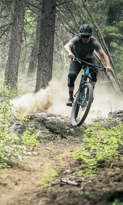
1 HABIT WHITE PAPER

2 PROPORTIONAL RESPONSE TECHNICAL SUMMARY Contents 1 Summary 1 2 Suspension for Mountain Bikes 2 3 Proportional Response 10 4 Experimental Validation of Suspension Response 12 5 Size Specific Kinematics 15 6 A New Suspension Platform 18 1 Summary Cannondale believes in creating the perfect ride for all our customers. We aspire to make bikes better and provide a more confident experience for every rider, no matter their size. Proportional Response is our new design philosophy. It is a distinct approach to bicycle design. By looking at each individual bike size and rider as its own unique system, we can engineer the optimal dynamic response and ride experience for each size rider. In giving that same performance to all size riders, everyone benefits and no one is left behind. Proportional Response improve the ride experience by providing the ideal braking performance and behavior, and improved overall peddling efficiency, regardless of frame size. By varying the frame kinematics by size, we are able to maintain constant anti-rise across the sizes. Leverage ratio rise has also been optimized per size. Larger bikes have received an increased leverage ratio rise, while smaller sizes have received a reduced leverage ratio rise. This allows us to compensate and better match the increased spring forces and air pressures associated with larger, heavier riders. The new Habit also sees the introduction of a 4-bar linkage suspension platform to Cannondale mountain bikes. By utilizing a 4-bar linkage we can tailor the anti-rise across the size run, which provides optimal traction under braking. This allows us to maintain the efficient pedaling characteristics that Cannondale is renowned for while also improving performance under braking. 2 Habit White Paper 1
3 2 Suspension for Mountain Bikes Mountain bike suspension performs three critical functions that define the ride dynamics: 1) Absorb the forces from the terrain; 2) control the bike s chassis behavior during accelerations (both braking and accelerating); 3) define the bike s efficiency and performance. The primary forces acting on a mountain bike are a) the gravitational force of the bike and rider, b) the inertial forces acting under longitudinal acceleration (braking and accelerating), c) the force from the chain during pedaling, d) the normal forces at the wheel contact patch and e) the acceleration reaction forces at the contact patches. An effective suspension system needs to be able handle these forces and balance bicycle performance during all riding conditions. 2.1 Weight Transfer Weight transfer has a strong impact on bicycle dynamics during accelerations, both positive (acceleration) and negative (braking). During braking, weight is transferred toward the front wheel. Consequently, the sprung body of the bike experiences a rotational pitching moment. As the body moves and pitches forward, the result is an extension of the rear suspension and a compression of the front suspension. This forward pitching motion under braking is referred to as dive. See Figure 1. During forward acceleration, the opposite occurs: Weight is transferred rearward, unloading the front wheel and loading the rear wheel. This results is a rearward pitching moment, called squat. The squat and dive behavior of a mountain bike is a result of the acceleration, the total weight transfer, the spring stiffness of the suspension and the geometric arrangement of the suspension members. The geometric arrangement of suspension is the area that a designer can control in order to provide desired suspension response. Of these, the suspension characteristics that have the greatest impact on the bicycle s dynamic performance are anti-rise, anti-squat, leverage ratio and pedal kickback. 2.2 Anti-Rise Anti-rise is a metric associated with braking performance. It is defined by the geometric arrangement of the suspension members that balance the moments and forces of a mountain bike during deceleration. By manipulating the arrangement of suspension members, the forces acting on the suspension springs can be reduced, which results in decreased pitching (dive) of the frame caused by weight transfer. During braking, the important forces acting on the bike are the inertia of the decelerating body and the tractive forces at the wheel contact patches. During deceleration, the resultant force line is defined as the line through the rear contact patch and the swingarm pivot point, as this pivot point is where the forces are transferred to the frame. The location at which the resultant force line crosses a vertical line from the front contact patch (vertical reaction line) is key in defining the anti-rise of the suspension. The ratio of the height of the resultant force line to the centerof-gravity height is the anti-rise. Anti-rise values above 100% cause the suspension to compress under braking. Values below 100% allow the frame to pitch forward, resulting in the rear suspension extending under braking. Anti-rise values less than 100% typically result in better suspension response under braking. See Figure 2. Figure 2 Representation of anti-rise. The resultant force line in this layout results in anti-rise of 85%. Through extensive testing we have found that optimum braking occurs at anti-rise values in the range of 40-65% with the suspension at sag. Desired anti-rise can vary by application. For example, cross country and downhill have differing loads and suspension requirements. Anti-rise values in this range ensure the bike s behavior under braking is more consistent, whether braking with the rear brake only or applying both the rear and front brakes simultaneously. This reduces the pitching moment of the frame and permits the rear wheel to extend. The right amount of extension helps the rear wheel maintain contact with the ground for greater traction during braking. In this extension state the rear suspension remains active at a reduced wheel rate, which increases the bump absorption capacity and reduces the bump forces transmitted to the rider. Figure 1 Graphical representation of weight transfer during braking. 2 Habit White Paper Habit White Paper 3
4 2.3 Anti-Squat Anti-squat is typically associated with pedaling performance. It is defined by the geometric arrangement of the suspension members that balance the moments and forces during forward acceleration. The anti-squat and resulting chassis behavior can be solved for, graphically, similar to anti-rise. First, project a line through the bike chainline. Second, project a line through the rear axle and pivot point (PP) along the length of the swingarm. The intersection of these lines is the instantaneous force center (IFC). This is the point through which both the tractive and chain drive forces are transmitted to the bike. For chain driven acceleration, the resultant force line is projected from the rear contact patch, through the IFC, to the vertical from the front contact patch. The intercept between the resultant force line and the vertical, through the front contact patch, characterizes the anti-squat behavior. Anti-squat is defined as the ratio of the height of the resultant force intercept with the vertical to the center of gravity height (weight transfer line). If the resultant force line intersects the vertical at the height of the center of gravity, then the suspension has 100% antisquat and the net pitching motion about the chassis is zero. When the resultant force line intersects below the center-of-gravity height, anti-squat is less than 100%, and there is a pitching moment about the chassis, which places the rear suspension in extension. It is important to note that the anti-squat changes through the suspension travel and as a function of gear ratio. Furthermore, anti-squat does not change the acceleration of the bike; it defines the pitching behavior of the frame and the reaction of the rear suspension in either compression or extension. See Figure 3. We have found that anti-squat values in the range of 70-90% (depending on platform requirements; e.g. XC vs DH) at sag provide the optimum pedaling characteristics across the entire cassette. This provides sufficient resistance to weight-transfer forces, which results in reduced suspension compression (bobbing) during pedaling. This delivers a high level of pedaling efficiency and consistent suspension behavior. By maintaining anti-squat levels slightly below 100%, the rear wheel is able to track more easily over the terrain when the rider is pedaling in technical sections. Maintaining anti-squat levels slightly below 100% also reduces pedal kickback. Both of these positive benefits of these anti-squat measures increase grip in low traction conditions. 2.4 Leverage Ratio In bicycle suspension, weight and packaging constraints do not allow for spring and damper assemblies to be mounted directly to the rear axle. Shocks tend to be positioned inside the front triangle and attached to the rear suspension at the swingarm or via mechanical linkage. The mechanical advantage between the rear wheel s displacement and the shock compression is the leverage ratio. Leverage ratio determines the spring rate at the rear wheel, the wheel rate, and the change in wheel rate as the suspension compresses. There are three general classifications of leverage ratio extensively used in mountain bike suspension: linear, progressive and digressive rates. Figure 4 displays examples of the three different classes of leverage ratio as a function of travel for a 130mm bike. A linear rate means that the leverage ratio remains constant through the suspension travel. This makes stiffness at the wheel equal at the beginning and end of the travel. A digressive rate means that the suspension stiffness decreases through the travel. Single pivot bikes with the shock mounted directly to the swingarm tend to have a digressive leverage ratio. A progressive rate means that the suspension becomes stiffer as travel increases. Through our extensive testing we have found that a progressive leverage curve performs better on the trail; the softer stiffness in early travel provides good sensitivity to small bumps, with improved support through the middle and ramped up stiffness to resist bottom out at the end of the travel. Figure 4 Three categories of leverage ratio; showing leverage ratio as a function of travel. Figure 3 Representation of anti-squat,, showing anti-squat less than 100%. Changes to the suspension geometry drive the angle of the resultant force line and subsequently the anti-squat. 4 Habit White Paper Habit White Paper 5
5 2.5 Pedal Kickback Pedal kickback, or pedal feedback, is a characteristic unique to full-suspension mountain bikes. Typically, as the rear suspension moves through its travel the rear wheel moves away from the bottom bracket. This increases the chain length between the front chainring and the rear sprocket. The growth in chain length introduces pedal kickback since the chain growth effectively causes counter clockwise rotation of the cranks and pedals. This is felt by the rider as a reverse pedal torque against the leading foot. Pedal kickback is typically measured in degrees. This behavior is illustrated in Figure 5, below. 2.6 Common Suspension Platforms Single Pivot In a single pivot layout, the rear wheel is directly connected to the swingarm. The swingarm being a single member connected to the front triangle at the pivot point. The rear axle path, therefore, has pure rotational motion, which is defined by the swingarm length and the position of the pivot point on the front triangle. Single pivot platforms are straightforward to design and manufacture. They can be configured to exhibit excellent pedaling efficiency or reduced pedal feedback, but not both simultaneously. They also provide very predictable ride characteristics. However, single-pivot designs have limitations in the braking performance they can achieve. This is dictated by the location of the main pivot location, which is usually defined for pedaling performance. The simple arc motion of the axle cannot be manipulated to reduce chain growth and pedal kickback values in the same way as more complex linkages. The result is a trade-off between braking performance and pedal efficiency. See Figure 6. Figure 5 The motion of the rear wheel away from the BB through the suspension travel creates chain growth, which introduces kickback at the crank and pedals. The location of the pivot point is the primary driver in defining the motion of the rear wheel relative to the bottom bracket and the growth of the chain relative to its initial length, as well as the rate of change in length. Larger rear sprockets and smaller front chainrings tend to increase pedal feedback. Under rapid rear suspension displacement, forces are transmitted to the rider s feet through the pedals. These forces create instability, discomfort, and can reduce control. Pedal kickback is most apparent during suspension movement over fast repeated bumps, deep suspension compressions, and particularly when braking in rough terrain. One of our design goals for all mountain bikes is to minimize kickback across the entire cassette range to improve climbing traction, braking performance and ride comfort. Figure 6 Representation of single pivot suspension layout, showing changes in anti-squat across the gear ratios. 6 Habit White Paper Habit White Paper 7
6 bar Linkage The 4-bar suspension linkage has been successfully and extensively used in both motorsports and automotive industries over the past half century. This is with good reason, as the additional degrees of freedom give the design engineer greater control over the suspension characteristics that is not possible with a single pivot layout. The 4-bar suspension is a multi-link mechanism comprising of 4 links, as the name suggests. Most 4-bars have the following four links: front triangle (rigid link), an upper link, a lower link, and a floating link. In this layout the frame acts as the rigid link. The upper and lower links are connected to the frame at their front ends, and their rear ends are connected by the floating link. Figure 7 depicts a typical 4-bar suspension layout. In this configuration the wheel assembly is mounted to the floating link. Both the upper and lower links rotate about their pivots on the main frame. The combined translation and rotation of the floating link is then defined by the relative rotation, length, orientation and separation of the upper and lower links. Figure 7 depicts a closed 4-bar linkage, which would be described as a clockwise system, since both the upper and lower links rotate in the same direction. 2.7 Disproportional Response Current mountain bikes, regardless of suspension layout, are typically designed around a single frame size. The kinematics are optimized for this one frame size. Geometries are also typically optimized around this one size. While this provides the desired response for riders of the middle sizes, large or small riders may not experience the same optimized suspension kinematics. The center of gravity location varies across the size range due to the different body dimensions and positions of the riders. Our testing has revealed that there is not a linear relationship between the center of gravity height and the front center dimension of the bike. Since the front-center typically varies linearly with size, this causes the anti-rise and anti-squat values to vary across the size range. As frame size increases, this effect results in reduced anti-squat, which decreases pedaling efficiency. It also reduces the anti-rise, which can improve braking performance, depending on the initial value. The opposite is true for small sizes. As frame and rider size decreases, there is an increase in anti-squat, which improves pedaling efficiency. It also increases the anti-rise, which can decrease braking performance. In this case, both lager and smaller riders suspension performance is compromised. See Figure 8. Figure 7 A typical application of a 4-bar linkage to mountain bike suspension. Mounting the wheel assembly to the floating link of a 4-bar system means that the instant center (pivot) is not a fixed point as it is on a single pivot design. This allows the design engineer to position the instant center at a virtual point in space, chosen to achieve the desired braking and pedaling characteristics. It also offers the ability to tune the axle path to reduce the effects of chain length growth and pedal kickback. However, this makes a 4-bar system more complicated, as careful attention must be paid to all aspects of the kinematics to ensure balanced performance. Figure 8 Representation of the linear change in length of the front center for three frame sizes, and the non-linear change in height of the CoG (indicated CoG heights are not to scale - for illustration purposes only). 8 Habit White Paper Habit White Paper 9


7 3 Proportional Response Our aim with Proportional Response is to address this discrepancy so that riders of all sizes can benefit from optimized suspension performance. This was achieved by engineering the ideal kinematic response in braking, pedaling, and leverage ratio for each frame and rider size independently. Utilizing the 4-bar suspension layout, and our new map of center of gravity heights for braking and pedaling scenarios, we can achieve the desired anti-rise and anti-squat characteristics for each individual frame size of the new Cannondale Habit. Figure 9 shows the change in anti-rise with frame size. For the new Habit with Proportional Response the anti-rise at sag is constant. Figure 10 shows that across the gear range anti-squat maintains high levels for efficient pedaling. The new Habit also benefits from a size-specific leverage ratio rise. This was achieved by adjusting the linkages and shock angles to compensate for different rider masses and resultant forces at the shocks. This provides all rider sizes with the optimal wheel rate and keeps the setup air spring pressures in the ideal range. Figure 11 shows the leverage ratio curves for each size of the new Habit. Figure 11 Representation of the leverage ratio, all sizes. Leverage ratio increases across the size range. Figure 9 Plot of the anti-rise values, proportional vs. non-proportional response. With Proportional Response anti-rise varies less across the size range (indicated by different colored series). Proportional Response delivers consistent dynamic response from each frame size for riders of all sizes. It provides a unique blend of intuitive braking performance with improved traction and control for all sizes. It balances pedal efficiency with low pedal kickback and consistent pedaling behavior in all possible gear combinations. The tailored leverage ratio rises of Proportional Response also provide improved small bump sensitivity, mid travel support and seamless bottom-out suspension across all frame sizes. The new Habit provides all riders with improved grip, control, balance, stability and maneuverability. With Proportional Response, small and large riders no longer sacrifice performance compared to a middle-sized rider. Now, riders of all sizes can enjoy identical optimized dynamic response because we engineer them to ride and feel the same. As a rider, you can ride faster, push harder, carve turns and brake harder with more traction and control. It provides an intuitive ride quality that lets you forget about the bike and focus on the ride. Figure 10 Plot of the anti-squat values across the gear range for a size medium with 32T chainring. Series indicate gear ratio (Front:Rear). 10 Habit White Paper Habit White Paper 11

8 4 Experimental Validation of Suspension Response At Cannondale we conduct extensive research across our platforms to ensure that we are delivering our riders with the perfect bikes for their ride. In developing Proportional Response, we identified that braking performance was a critical area that could deliver significant gains in mountain bike performance for different sized riders. Numerous experiments were conducted to gather field data and validate our kinematic models. Vehicle dynamics were studied using a wide range of bicycle telemetry including multi-axis accelerometers, gyroscopes, brake pressure sensors, and speed traps with on-course timing gates. 4.1 Steady State Testing Steady state testing was used to identify and map the center of gravity height for riders of different sizes under both braking and pedaling scenarios. We were also able to validate our models for anti-squat and anti-rise from the dynamic response of the bikes under both braking and pedaling. Using this validated data for center of gravity height and dynamic anti-rise and anti-squat, we can accurately predict, engineer and optimize the bike s response for optimal braking and pedaling. improved control upon rear wheel lockup during hard and abrupt brake applications. On the 4-bar linkage, the lower anti-rise leads to 20-30% greater extension of the suspension under braking compared to the single pivot. This allows the rear suspension to operate in a lower part of the travel, which provides a suppler ride and improved traction compared to the single pivot. See Figure 12. This permits the suspension to better isolate the frame and rider from the forces generated when braking over rough terrain. Therefore, the lower anti-rise setup reduces vertical accelerations transmitted to the frame and improves ride comfort and reduces fatigue. Further testing of bikes with the chain removed showed that eliminating pedal kickback had a positive impact on braking performance. This reduced the forces transmitted to the frame and pedals as well as reduced the settling time of the suspension after moving over obstacles during braking. The results demonstrate the advantage of reduced pedal kickback in a suspension design. The rider experiences reduced force feedback through the pedals, reduced fatigue, and improved bike control during braking. Figure 13 Prototype in testing. Figure 12 Representation of the rear suspension behavior in braking, rear brake only, single pivot vs 4-bar. Note that the 4-bar permits greater deceleration and brake force. 4.2 Active Suspension Under Braking Experiments were conducted to investigate the dynamic response of rear suspension under braking and its effect on traction. Initial testing specifically compared a single pivot design (anti-rise = 100%) to a 4-bar linkage (anti-rise = 50-60%). Telemetry data showed that both suspension platforms were active during braking and able to track over bumps and holes under brake loads. However, the lower anti-rise of the 4-bar linkage provided improved braking performance and traction. It also demonstrated 12 Habit White Paper Habit White Paper 13


9 4.3 Better Braking for Higher Speed Several experiments were designed to specifically compare the performance benefits of the lower anti-rise 4-bar system against the single pivot design. A timing gate speed trap was used to precisely measure performance against the clock over a controlled course. Braking duration and speed were compared to determine if lower anti-rise provides a faster ride through improved braking performance. In all test conditions the 4-bar suspension outperformed the single pivot configuration. The lower anti-rise produced higher decelerations during braking with both front and rear brakes; 20% higher than the single pivot. When only the rear brake was applied (as a control condition) the difference in deceleration increased up to 25%. See Figure Size Specific Kinematics We mapped the mechanical behavior of the suspension system under various loading conditions using advanced vehicle dynamic analysis. At the heart of vehicle dynamics is the Center of Gravity (CoG). The CoG represents the vehicle s mass and location in space. It is at this point that all rectilinear, angular, and rotational forces are considered to act on the vehicle. At the CoG of a vehicle, all components are idealized as moving together as single concentrated mass. For example, when a mountain bike is decelerating, all its parts are considered to slow at the same time as a single unit. We needed to determine the location of the center of gravity to precisely analyze and understand how a mountain bike behaves. Only then could we measure, analyze, and improve its behavior and performance. For our investigation, we treated the mountain bike and rider as a single system, as it is the sum of these two masses and individual CoG s that determine the center of gravity of the system. See Figure 16. Figure 14 Deceleration achieved during testing by suspension platform. When braking and cornering were combined, the 4-bar setup delivered higher average corner speed compared to the single pivot. See Figure 15. The lower anti-rise configuration demonstrated improved control when cornering and braking simultaneously. In all cases the reduced anti-rise setup provided greater control and more speed. Feedback from our test riders during experiments also favored the lower anti-rise setup, regardless of rider size or weight. Figure 16 Test rider on instrumented bicycle with approximate centers of gravity shown. Figure 15 Plot of top speed and braking duration for the 4-bar and Single Pivot suspension systems. Diamonds indicate average of the set. Mountain bikes experience very different dynamics compared to motorized vehicles. The highest percentage of the overall mass and its locations on a bike is dictated by the rider s mass rather than the bike s frame/chassis. The rider s weight contributes over 80% of the overall system weight. For comparison, the same rider s weight on a typical motorcycle is less than 30% of the system weight. The same rider/driver in a small car amounts to less than 10% of the total weight. This means that the relative motion of the rider s center of gravity has a much more significant effect on the dynamics of a bicycle system when compared to other vehicles. It is therefore crucial to bicycle performance that we understand the location of the center of gravity in different riding conditions. 14 Habit White Paper Habit White Paper 15


10 Three critical riding scenarios were identified and the location of the center of gravity mapped for difference sized riders and bikes. These scenarios are generally described as: Pedaling Standing, Seated Braking Figure 17 A rider in three critical riding positions; standing pedaling, seated pedaling and braking. The center of gravity height for braking and the center of gravity height for pedaling are not the same. See Figure 17. In fact, these heights also change across the bike size range, due to the different rider body dimensions and their body positioning. From this we determined that designing the kinematics around a single center of gravity height for all bicycle sizes means, at best, only one size is optimized; other size riders have a different ride experience and suffer from inferior performance. This led to an in-depth study of the center of gravity location for riders of different height and mass. From this we determined the optimal centers of gravity around which to design different sized bikes. See Figure 18. the ideal bike as size medium, it is now possible to vary the kinematic layout so that every bike and rider size will perform in the same manner. Commonly, as frame size increases, front center and wheelbase increase linearly. However, the center of gravity height of the rider increases at a higher rate for both pedaling and braking positions. For larger riders, this reduces anti-squat relative to the medium size. This translates to increased suspension displacement (pedal bob) and lower pedaling efficiency. The larger riders also experience lower antirise compared to the kinematics of the middle size. On a single-pivot system this improves the braking behavior. However, for bikes with already low anti-rise, the further reduction on larger sizes can produce a larger pitching moment on the frame and higher extension of the rear suspension under braking than desired, potentially limiting negative travel. For the smaller rider, the opposite is true. The center of gravity height decreases at a higher rate than the reduction in front center and wheelbase. This results in increased anti-squat on smaller frame sizes. This can improve pedaling efficiency if the designed anti-squat is below 100%. Otherwise, it can have the undesired effect of suspension extension under pedaling loads. During braking, the change in center of gravity results in greater anti-rise, which reduces the braking performance. This behavior illustrates that the suspension performance for larger and smaller riders can be improved by optimizing the suspension kinematics by size, rather than using a single kinematic across the size range. This is Proportional Response. Figure 19 Location of center of gravity during pedaling and braking by frame size (XS, S, M, L, XL). Origin at BB. Figure 18 Images of three different sized riders (XS, Medium and XL) all on the same down slope braking at the same point. The study showed that the rider s center of gravity height varied significantly between rider size in both braking and pedaling. See Figure 19. Based on the resultant centers of gravity for each bike and rider size in both braking and pedaling scenarios and how these points change it was apparent that there was room for improvement in the way most mountain bike suspension systems are designed. First, existing design practice typically assumes a constant center of gravity for both braking and pedaling. Secondly, it is assumed that all riders share the same center of gravity location. Using this knowledge of the differences in center of gravity locations, rather than designing 16 Habit White Paper Habit White Paper 17

11 6 A New Suspension Platform The combination of Proportional Response and our new 4-bar suspension system delivers an improved ride quality based on optimized dynamic behavior and suspension performance, independent of rider size. By reconfiguring the 4-bar linkages for each frame size, and manipulating the instant center, we can optimize the anti-rise and anti-squat response for each size individually. Larger riders no longer suffer from decreased pedaling efficiency, nor smaller riders from poor braking performance. This means we can deliver the perfect ride experience to all our riders, regardless of their size. The combined system of Proportional Response and the 4-bar linkage suspension represents a completely new way of designing full-suspension mountain bikes. This highly versatile system can be engineered and implemented across a range of suspension travel demands and rider requirements. Until now, if you didn t ride a size medium, your bike suffered from compromised suspension kinematics. With Proportional Response on the new Habit, now all riders can experience their perfect ride. 18 Habit White Paper Habit White Paper 19

12
SUMMARY OF STANDARD K&C TESTS AND REPORTED RESULTS
 Description of K&C Tests SUMMARY OF STANDARD K&C TESTS AND REPORTED RESULTS The Morse Measurements K&C test facility is the first of its kind to be independently operated and made publicly available in
Cane Creek Double Barrel Instructions
 Cane Creek Double Barrel Instructions Congratulations on your purchase of the Cane Creek Double Barrel rear shock. Developed in partnership with Öhlins Racing, the Double Barrel brings revolutionary suspension
iracing.com Williams-Toyota FW31 Quick Car Setup Guide
 iracing.com Williams-Toyota FW31 Quick Car Setup Guide In this guide we will briefly explain a number of key setup parameters which are distinct to the FW31 and which are new to iracing vehicles. We hope
MODELING SUSPENSION DAMPER MODULES USING LS-DYNA
 MODELING SUSPENSION DAMPER MODULES USING LS-DYNA Jason J. Tao Delphi Automotive Systems Energy & Chassis Systems Division 435 Cincinnati Street Dayton, OH 4548 Telephone: (937) 455-6298 E-mail: Jason.J.Tao@Delphiauto.com
A double-wishbone type suspension is used in the front. A multi-link type suspension is used in the rear. Tread* mm (in.) 1560 (61.
 1560 (61.") CHASSIS SUSPENSION AND AXLE CH-69 SUSPENSION AND AXLE SUSPENSION 1. General A double-wishbone type suspension is used in the front. A multi-link type suspension is used in the rear. 08D0CH111Z Specifications
CHASSIS SUSPENSION AND AXLE CH-69 SUSPENSION AND AXLE SUSPENSION 1. General A double-wishbone type suspension is used in the front. A multi-link type suspension is used in the rear. 08D0CH111Z Specifications
Design and Integration of Suspension, Brake and Steering Systems for a Formula SAE Race Car
 Design and Integration of Suspension, Brake and Steering Systems for a Formula SAE Race Car Mark Holveck 01, Rodolphe Poussot 00, Harris Yong 00 Final Report May 5, 2000 MAE 340/440 Advisor: Prof. S. Bogdonoff
Design and Analysis of suspension system components
 Design and Analysis of suspension system components Manohar Gade 1, Rayees Shaikh 2, Deepak Bijamwar 3, Shubham Jambale 4, Vikram Kulkarni 5 1 Student, Department of Mechanical Engineering, D Y Patil college
KINEMATICS OF REAR SUSPENSION SYSTEM FOR A BAJA ALL-TERRAIN VEHICLE.
 International Journal of Mechanical Engineering and Technology (IJMET) Volume 8, Issue 8, August 2017, pp. 164 171, Article ID: IJMET_08_08_019 Available online at http://www.iaeme.com/ijmet/issues.asp?jtype=ijmet&vtype=8&itype=8
Discussion Paper. Effect of Anti-Squat Adjustment in Solid Axle 4 Link Rear Suspension Systems
 Discussion Paper Effect of Anti-Squat Adjustment in Solid Axle 4 Link Rear Suspension Systems Example used is Commodore 1990 VG utility fitted with Whiteline KTA103 adjustable upper trailing arms. Prepared
Suspension systems and components
 Suspension systems and components 2of 42 Objectives To provide good ride and handling performance vertical compliance providing chassis isolation ensuring that the wheels follow the road profile very little
Welcome and enjoy tuning your Manitou ABS+ Compression Damping System! Purposefully engineered to raise your expectations.
 Welcome and enjoy tuning your Manitou ABS+ Compression Damping System! Purposefully engineered to raise your expectations. PLEASE READ SERVICE INSTRUCTIONS PRIOR TO BEGINNING WORK. While revalving your
Torque steer effects resulting from tyre aligning torque Effect of kinematics and elastokinematics
 P refa c e Tyres of suspension and drive 1.1 General characteristics of wheel suspensions 1.2 Independent wheel suspensions- general 1.2.1 Requirements 1.2.2 Double wishbone suspensions 1.2.3 McPherson
Development of a Multibody Systems Model for Investigation of the Effects of Hybrid Electric Vehicle Powertrains on Vehicle Dynamics.
 Development of a Multibody Systems Model for Investigation of the Effects of Hybrid Electric Vehicle Powertrains on Vehicle Dynamics. http://dx.doi.org/10.3991/ijoe.v11i6.5033 Matthew Bastin* and R Peter
August 2001 THINGS THAT MAKE SPRING CHANGES WORK BACKWARDS
 August 2001 WELCOME Mark Ortiz Automotive is a chassis consulting service primarily serving oval track and road racers. This newsletter is a free service intended to benefit racers and enthusiasts by offering
White Paper: The Physics of Braking Systems
 White Paper: The Physics of Braking Systems The Conservation of Energy The braking system exists to convert the energy of a vehicle in motion into thermal energy, more commonly referred to as heat. From
SPMM OUTLINE SPECIFICATION - SP20016 issue 2 WHAT IS THE SPMM 5000?
 SPMM 5000 OUTLINE SPECIFICATION - SP20016 issue 2 WHAT IS THE SPMM 5000? The Suspension Parameter Measuring Machine (SPMM) is designed to measure the quasi-static suspension characteristics that are important
Procedia Engineering 00 (2009) Mountain bike wheel endurance testing and modeling. Robin C. Redfield a,*, Cory Sutela b
 Mountain bike wheel endurance testing and modeling. Robin C. Redfield a,*, Cory Sutela b") Procedia Engineering (29) Procedia Engineering www.elsevier.com/locate/procedia 9 th Conference of the International Sports Engineering Association (ISEA) Mountain bike wheel endurance testing and modeling
Procedia Engineering (29) Procedia Engineering www.elsevier.com/locate/procedia 9 th Conference of the International Sports Engineering Association (ISEA) Mountain bike wheel endurance testing and modeling
2005 Reign SERIES DUAL-SUSPENSION BIKE TECHNIC MANUAL
 2005 Reign SERIES DUAL-SUSPENSION BIKE TECHNIC MANUAL 1 CONTENTS PRODUCT FEATURE SECTION 1. SIZING SECTION 2. REAR SHOCK SECTION 3. TORGUE SETTING SECTION 4. EXPLOADE DRAWING 2 Reign Product feature This
Tech Tip: Trackside Tire Data
 Using Tire Data On Track Tires are complex and vitally important parts of a race car. The way that they behave depends on a number of parameters, and also on the interaction between these parameters. To
SPMM OUTLINE SPECIFICATION - SP20016 issue 2 WHAT IS THE SPMM 5000?
 SPMM 5000 OUTLINE SPECIFICATION - SP20016 issue 2 WHAT IS THE SPMM 5000? The Suspension Parameter Measuring Machine (SPMM) is designed to measure the quasi-static suspension characteristics that are important
The Mark Ortiz Automotive
 August 2004 WELCOME Mark Ortiz Automotive is a chassis consulting service primarily serving oval track and road racers. This newsletter is a free service intended to benefit racers and enthusiasts by offering
Front Suspension. Setup and Tuning Guide
 Front Suspension Setup and Tuning Guide GEN.00000000005623 GEN0000000000000 Rev A 2015 SRAM, 2018 SRAM, LLC LLC Table of Contents Introduction... 4 Set Sag...5 Dampers... 6 Air Springs - Solo Air, DebonAir,
STUDY OF ROLL CENTER SAURABH SINGH *, SAGAR SAHU ** ABSTRACT
 STUDY OF ROLL CENTER SAURABH SINGH *, SAGAR SAHU ** *, ** Mechanical engineering, NIT B ABSTRACT As our solar car aims to bring new green technology to cope up with the greatest challenge of modern era
Skid against Curb simulation using Abaqus/Explicit
 Visit the SIMULIA Resource Center for more customer examples. Skid against Curb simulation using Abaqus/Explicit Dipl.-Ing. A. Lepold (FORD), Dipl.-Ing. T. Kroschwald (TECOSIM) Abstract: Skid a full vehicle
Introduction.. pg.4. Basic Terms & Shock Setup Overview.. pg.6. General Maintenance. pg.9. Coil Shock Setup pg.10. Setting and Adjusting Sag... pg.
 TABLE OF CONTENTS Introduction.. pg.4 Basic Terms & Shock Setup Overview.. pg.6 General Maintenance. pg.9 Coil Shock Setup pg.10 Setting and Adjusting Sag.... pg.12 Suspension Settings Glory.... pg.13
SUSPENSION OF A MOUNTAIN BIKE SVOČ FST Bc. Vít Prošek University of West Bohemia Univerzitni 8, Pilsen Czech Republic
 SUSPENSION OF A MOUNTAIN BIKE SVOČ FST 211 Bc. Vít Prošek University of West Bohemia Univerzitni 8, 36 14 Pilsen Czech Republic ABSTRACT This work is concerned about suspended mountain bikes, especially
SUSPENSION SETUP GUIDE
 For your Pivot suspension equipped bike to pedal and descend at its best, it is important to tune the suspension properly. Use this guide to familiarize yourself with the Pivot suspension setup procedures
TABLE OF CONTENTS. Frames Technical Data & Features
 TABLE OF CONTENTS Dual Suspension Frame Overview........................ 2 Introduction.................................... 3 Basic Terms & Shock Setup Overview...................... 4 Suspension SAG Recommendation
Chapter 2. Background
 Chapter 2 Background The purpose of this chapter is to provide the necessary background for this research. This chapter will first discuss the tradeoffs associated with typical passive single-degreeof-freedom
ROLL CENTER You can adjust the front and rear roll centers of the XB8 by changing the mounting locations of various components.
 Your XRAY XB8 luxury nitro buggy is a top competition, precision racing machine that features multiple adjustments that allow you to set up for any track condition. The XB8 includes innovative set-up features
The Synaptic Damping Control System:
 The Synaptic Damping Control System: increasing the drivers feeling and perception by means of controlled dampers Giordano Greco Magneti Marelli SDC Vehicle control strategies From passive to controlled
Design, Modelling & Analysis of Double Wishbone Suspension System
 Design, Modelling & Analysis of Double Wishbone Suspension System 1 Nikita Gawai, 2 Deepak Yadav, 3 Shweta Chavan, 4 Apoorva Lele, 5 Shreyash Dalvi Thakur College of Engineering & Technology, Kandivali
SUSPENSION SETUP GUIDE
 For your Pivot suspension equipped bike to pedal and descend at its best, it is important to tune the suspension properly. Use this guide to familiarize yourself with the Pivot suspension setup procedures
Chassis development at Porsche
 Chassis development at Porsche Determining factors Challenges automotive industry Challenges chassis development e-mobility product differentiation customization driving resistance vehicle mass resource
ENERGY ANALYSIS OF A POWERTRAIN AND CHASSIS INTEGRATED SIMULATION ON A MILITARY DUTY CYCLE
 U.S. ARMY TANK AUTOMOTIVE RESEARCH, DEVELOPMENT AND ENGINEERING CENTER ENERGY ANALYSIS OF A POWERTRAIN AND CHASSIS INTEGRATED SIMULATION ON A MILITARY DUTY CYCLE GT Suite User s Conference: 9 November
Kinematic Analysis of Roll Motion for a Strut/SLA Suspension System Yung Chang Chen, Po Yi Tsai, I An Lai
 Kinematic Analysis of Roll Motion for a Strut/SLA Suspension System Yung Chang Chen, Po Yi Tsai, I An Lai Abstract The roll center is one of the key parameters for designing a suspension. Several driving
TECHNICAL NOTE. NADS Vehicle Dynamics Typical Modeling Data. Document ID: N Author(s): Chris Schwarz Date: August 2006
: Chris Schwarz Date: August 2006") TECHNICAL NOTE NADS Vehicle Dynamics Typical Modeling Data Document ID: N06-017 Author(s): Chris Schwarz Date: August 2006 National Advanced Driving Simulator 2401 Oakdale Blvd. Iowa City, IA 52242-5003
TECHNICAL NOTE NADS Vehicle Dynamics Typical Modeling Data Document ID: N06-017 Author(s): Chris Schwarz Date: August 2006 National Advanced Driving Simulator 2401 Oakdale Blvd. Iowa City, IA 52242-5003
Unsprung Mass The Myths and Realities Closing the Circle
 Unsprung Mass The Myths and Realities Closing the Circle A study into the dynamic implications and opportunities of an unsprung-mounted drivetrain. Andrew Watts CTO, Protean Electric Dr Chris Hilton, Chief
Volkswagen DCC Adaptive Chassis Control - Design and Function DCC Adaptive Chassis Control. Basics of the damping system
 Volkswagen DCC Adaptive Chassis Control - Design and Function DCC Adaptive Chassis Control The rule for suspension systems has always been that increasing sportiness compromises the ride. In this new system
Fork Set-Up Guide DVOSUSPENSION.COM
 Fork Set-Up Guide DVOSUSPENSION.COM Fork Set-Up Guide for Other Languages Pre-Ride Check DOWNLOAD FRANÇAIS ITALIANO DEUTSCH ESPAÑOL Guide d ajustement Guida di sintonia Tuning guide Guía de ajuste 6. Compress
DUAL SUSPENSION USER S MANUAL
 DUAL SUSPENSION USER S MANUAL 2018.April TABLE OF CONTENTS INTRODUCTION 3 BASIC TERMS & SHOCK SETUP OVERVIEW 3 TERMS 3 SETUP 3 SAG 4 REBOUND DAMPING 4 PEDAL PLATFORM 4 GENERAL MAINTENANCE 4 FRONT SUSPENSION
Transmission Error in Screw Compressor Rotors
 Purdue University Purdue e-pubs International Compressor Engineering Conference School of Mechanical Engineering 2008 Transmission Error in Screw Compressor Rotors Jack Sauls Trane Follow this and additional
The goal of the study is to investigate the effect of spring stiffness on ride height and aerodynamic balance.
 OptimumDynamics - Case Study Investigating Aerodynamic Distribution Goals Investigate the effect of springs on aerodynamic distribution Select bump stop gap Software OptimumDynamics The case study is broken
Mathematical Modelling and Simulation Of Semi- Active Suspension System For An 8 8 Armoured Wheeled Vehicle With 11 DOF
 Mathematical Modelling and Simulation Of Semi- Active Suspension System For An 8 8 Armoured Wheeled Vehicle With 11 DOF Sujithkumar M Sc C, V V Jagirdar Sc D and MW Trikande Sc G VRDE, Ahmednagar Maharashtra-414006,
RED RAVEN, THE LINKED-BOGIE PROTOTYPE. Ara Mekhtarian, Joseph Horvath, C.T. Lin. Department of Mechanical Engineering,
 RED RAVEN, THE LINKED-BOGIE PROTOTYPE Ara Mekhtarian, Joseph Horvath, C.T. Lin Department of Mechanical Engineering, California State University, Northridge California, USA Abstract RedRAVEN is a pioneered
HVE Vehicle Accelerometers: Validation and Sensitivity
 WP#-2015-3 HVE Vehicle Accelerometers: Validation and Sensitivity Kent W. McKee, M.E.Sc., P.Eng., Matthew Arbour, B.A.Sc., Roger Bortolin, P.Eng., and James R. Hrycay, M.A.Sc., P.Eng. HRYCAY Consulting
Improvement of Vehicle Dynamics by Right-and-Left Torque Vectoring System in Various Drivetrains x
 Improvement of Vehicle Dynamics by Right-and-Left Torque Vectoring System in Various Drivetrains x Kaoru SAWASE* Yuichi USHIRODA* Abstract This paper describes the verification by calculation of vehicle
E.C.C. and AirTail Compressor Kit For the Airtail Suspension System Setup Instructions
 E.C.C. and AirTail Compressor Kit For the Airtail Suspension System Setup Instructions Note: Please read and follow the Installation Instructions first, then read and follow these Setup Instructions completely
Fundamentals of Steering Systems ME5670
 Fundamentals of Steering Systems ME5670 Class timing Monday: 14:30 Hrs 16:00 Hrs Thursday: 16:30 Hrs 17:30 Hrs Lecture 3 Thomas Gillespie, Fundamentals of Vehicle Dynamics, SAE, 1992. http://www.me.utexas.edu/~longoria/vsdc/clog.html
Technical Report Lotus Elan Rear Suspension The Effect of Halfshaft Rubber Couplings. T. L. Duell. Prepared for The Elan Factory.
 Technical Report - 9 Lotus Elan Rear Suspension The Effect of Halfshaft Rubber Couplings by T. L. Duell Prepared for The Elan Factory May 24 Terry Duell consulting 19 Rylandes Drive, Gladstone Park Victoria
Wheeled Mobile Robots
 Wheeled Mobile Robots Most popular locomotion mechanism Highly efficient on hard and flat ground. Simple mechanical implementation Balancing is not usually a problem. Three wheels are sufficient to guarantee
ABS. Prof. R.G. Longoria Spring v. 1. ME 379M/397 Vehicle System Dynamics and Control
 ABS Prof. R.G. Longoria Spring 2002 v. 1 Anti-lock Braking Systems These systems monitor operating conditions and modify the applied braking torque by modulating the brake pressure. The systems try to
TOO TECH RACING SET-UP INSTRUCTIONS (For Non Twin Chamber Showa & KYB)
") TOO TECH RACING SET-UP INSTRUCTIONS (For Non Twin Chamber Showa & KYB) STEP 1: Measure suspension "Race Sag". (Most important adjustment there is) First: Put the bike on a center stand and release the
TOO TECH RACING SET-UP INSTRUCTIONS (For Non Twin Chamber Showa & KYB) STEP 1: Measure suspension "Race Sag". (Most important adjustment there is) First: Put the bike on a center stand and release the
Three variants will be available in Australia, details on the Goldwing Tour are as follows:
 The 2018 Goldwing The next generation of Goldwing. The new Gold Wing series offers a completely revised package, promising to be more exciting and offer a more fulfilling, superb riding experience to riders
Linear Shaft Motors in Parallel Applications
 Linear Shaft Motors in Parallel Applications Nippon Pulse s Linear Shaft Motor (LSM) has been successfully used in parallel motor applications. Parallel applications are ones in which there are two or
Analysis and control of vehicle steering wheel angular vibrations
 Analysis and control of vehicle steering wheel angular vibrations T. LANDREAU - V. GILLET Auto Chassis International Chassis Engineering Department Summary : The steering wheel vibration is analyzed through
LESSON Transmission of Power Introduction
 LESSON 3 3.0 Transmission of Power 3.0.1 Introduction Earlier in our previous course units in Agricultural and Biosystems Engineering, we introduced ourselves to the concept of support and process systems
NEW DESIGN AND DEVELELOPMENT OF ESKIG MOTORCYCLE
 NEW DESIGN AND DEVELELOPMENT OF ESKIG MOTORCYCLE Eskinder Girma PG Student Department of Automobile Engineering, M.I.T Campus, Anna University, Chennai-44, India. Email: eskindergrm@gmail.com Mobile no:7299391869
FORK FLOAT 29. Before You Ride. Setting Fork Air Pressure. Travel 3.9 in./100 mm 4.7 in./120 mm 5.1 in./130 mm. Features/Adjustments
 Worldwide 1.800.FOX.SHOX (1.800.369.7469) FORK- 2014 32 FLOAT 29 Travel 3.9 in./100 mm 4.7 in./120 mm 5.1 in./130 mm Features/Adjustments Factory FIT icd; 100; Kashima coated upper tubes, 1-1/8 straight
ROLLOVER CRASHWORTHINESS OF A RURAL TRANSPORT VEHICLE USING MADYMO
 ROLLOVER CRASHWORTHINESS OF A RURAL TRANSPORT VEHICLE USING MADYMO S. Mukherjee, A. Chawla, A. Nayak, D. Mohan Indian Institute of Technology, New Delhi INDIA ABSTRACT In this work a full vehicle model
Shock Absorbers What is Ride Control Vehicle Dynamics Suspension System Shock Absorbers Struts Terminology
 Home Tech Support Shock Absorbers Shock Absorbers What is Ride Control Vehicle Dynamics Suspension System Shock Absorbers Struts Terminology A BRIEF HISTORY These first shock absorbers were simply two
HUSQVARNA SMR449/SMR511 A NEW BREED
 HUSQVARNA SMR449/SMR511 A NEW BREED Husqvarna has always been the star of the supermotard world. Husqvarna's numerous successes in this sport are accompanied by the commercial success obtained with innovative
Reduction of Self Induced Vibration in Rotary Stirling Cycle Coolers
 Reduction of Self Induced Vibration in Rotary Stirling Cycle Coolers U. Bin-Nun FLIR Systems Inc. Boston, MA 01862 ABSTRACT Cryocooler self induced vibration is a major consideration in the design of IR
RXF34/RXF36. Front Fork. Owner s Manual/ Mounting Instructions
 Kit Contents Description Part No Pcs Front Fork RXF34/ RXF36 1 Before installing this product, read this manual. The front fork is an important part of your bicycle and will affect the stability. Please
STaSIS / Öhlins Motor Sport Suspension
 STaSIS / Öhlins Motor Sport Suspension Damper Model Information Öhlins LMJ Series Damper: Öhlins LMJ stock car shock absorbers are based on the race proven Öhlins 46HRC. A shock absorber featuring a large
Chapter 4. Vehicle Testing
 Chapter 4 Vehicle Testing The purpose of this chapter is to describe the field testing of the controllable dampers on a Volvo VN heavy truck. The first part of this chapter describes the test vehicle used
G-Vectoring Control. Press information. June Mazda Canada Inc 1
 G-Vectoring Control Press information June 2016 Mazda Canada Inc 1 1. Introduction - The tireless pursuit of Jinba-Ittai Mazda aims to offer vehicles that provide driving pleasure and enrich the lives
RXF36 Coil. Front Fork. Owner s Manual/ Mounting Instructions
 Kit Contents Description Part No Pcs Front Fork RXF36 Coil 1 Before installing this product, read this manual. The front fork is an important part of your bicycle and will affect the stability. Please
Sport Shieldz Skull Cap Evaluation EBB 4/22/2016
 Summary A single sample of the Sport Shieldz Skull Cap was tested to determine what additional protective benefit might result from wearing it under a current motorcycle helmet. A series of impacts were
Part 1. The three levels to understanding how to achieve maximize traction.
 Notes for the 2017 Prepare to Win Seminar Part 1. The three levels to understanding how to achieve maximize traction. Level 1 Understanding Weight Transfer and Tire Efficiency Principle #1 Total weight
PRECISION BELLOWS COUPLINGS
 PRECISION BELLOWS COUPLINGS Bellows couplings are used where precise rotation, high speeds, and dynamic motion must be transmitted. They exhibit zero backlash and a high level of torsional stiffness, offering
Simple Gears and Transmission
 Simple Gears and Transmission Simple Gears and Transmission page: of 4 How can transmissions be designed so that they provide the force, speed and direction required and how efficient will the design be?
Study on System Dynamics of Long and Heavy-Haul Train
 Copyright c 2008 ICCES ICCES, vol.7, no.4, pp.173-180 Study on System Dynamics of Long and Heavy-Haul Train Weihua Zhang 1, Guangrong Tian and Maoru Chi The long and heavy-haul train transportation has
VEHICLE ANTI-ROLL BAR ANALYZED USING FEA TOOL ANSYS
 VEHICLE ANTI-ROLL BAR ANALYZED USING FEA TOOL ANSYS P. M. Bora 1, Dr. P. K. Sharma 2 1 M. Tech. Student,NIIST, Bhopal(India) 2 Professor & HOD,NIIST, Bhopal(India) ABSTRACT The aim of this paper is to
STX22Air. Shock absorber for Specialized Enduro, Stumpjumper, Rhyme and Levo. Owner s Manual/ Mounting Instructions
 Kit Contents Description Part No Pcs Shock absorber STXAir Before installing this product, read this manual. The shock absorber is an important part of your bicycle and will affect the stability. Please
Case study on Carbon Fiber spring suspension for FORD ENDEVOUR THUNDER+
 Case study on Fiber spring suspension for FORD ENDEVOUR THUNDER+ Krishna Balamurali (M.S Automotive Engineering) Principal Engineer, NV Dynamnics Abstract: Most of the SUV s (sports utility vehicles) available
Moments. It doesn t fall because of the presence of a counter balance weight on the right-hand side. The boom is therefore balanced.
 Moments The crane in the image below looks unstable, as though it should topple over. There appears to be too much of the boom on the left-hand side of the tower. It doesn t fall because of the presence
CHASSIS DYNAMICS TABLE OF CONTENTS A. DRIVER / CREW CHIEF COMMUNICATION I. CREW CHIEF COMMUNICATION RESPONSIBILITIES
 CHASSIS DYNAMICS TABLE OF CONTENTS A. Driver / Crew Chief Communication... 1 B. Breaking Down the Corner... 3 C. Making the Most of the Corner Breakdown Feedback... 4 D. Common Feedback Traps... 4 E. Adjustment
1990 INTEGRA CHASSIS. - Double- Wishbone Front Suspension -
 c 1990 INTEGRA CHASSIS DESIGN OBJECTIVES In designing the new Integra's chassis, the goals were: a high degree oflinear stability, precise and quick transient response, a favorable front/rear balance for
Hybrid Architectures for Automated Transmission Systems
 1 / 5 Hybrid Architectures for Automated Transmission Systems - add-on and integrated solutions - Dierk REITZ, Uwe WAGNER, Reinhard BERGER LuK GmbH & Co. ohg Bussmatten 2, 77815 Bühl, Germany (E-Mail:
TO DIVE O R... Tony Foale January 1997
 TO DIVE O R... Tony Foale January 1997 Over the past couple of years the subject of anti-dive has received much attention, but there seems to be some divergence of opinion over the value of the Japanese
RXF34/RXF36. Front Fork. Owner s Manual/ Mounting Instructions
 Kit Contents Description Part No Pcs RXF34 29 Air TTX22 FG341x 1512 1 120/140/160 mm RXF36 29 Air TTX22 FG361x 171x 1 120/140/150/160 mm RXF36 29 Air STX22 FG361x 1731 1 150/160 mm RXF36 27.5 Air TTX22
 FORK- 2014 32 FLOAT 27.5 Travel 3.9 in./100 mm 4.7 in./120 mm 5.1 in./130 mm 5.5 in./140 mm 5.9 in./150 mm Features/Adjustments Factory FIT icd; 100; Kashima coated upper tubes, 1-1/8 straight or 1.5 tapered
Electromagnetic Fully Flexible Valve Actuator
 Electromagnetic Fully Flexible Valve Actuator A traditional cam drive train, shown in Figure 1, acts on the valve stems to open and close the valves. As the crankshaft drives the camshaft through gears
Active Suspensions For Tracked Vehicles
 Active Suspensions For Tracked Vehicles Y.G.Srinivasa, P. V. Manivannan 1, Rajesh K 2 and Sanjay goyal 2 Precision Engineering and Instrumentation Lab Indian Institute of Technology Madras Chennai 1 PEIL
Appendix A: Motion Control Theory
 Appendix A: Motion Control Theory Objectives The objectives for this appendix are as follows: Learn about valve step response. Show examples and terminology related to valve and system damping. Gain an
MOTOR VEHICLE HANDLING AND STABILITY PREDICTION
 MOTOR VEHICLE HANDLING AND STABILITY PREDICTION Stan A. Lukowski ACKNOWLEDGEMENT This report was prepared in fulfillment of the Scholarly Activity Improvement Fund for the 2007-2008 academic year funded
Enhancing Wheelchair Mobility Through Dynamics Mimicking
 Proceedings of the 3 rd International Conference Mechanical engineering and Mechatronics Prague, Czech Republic, August 14-15, 2014 Paper No. 65 Enhancing Wheelchair Mobility Through Dynamics Mimicking
Designing and Hard Point Optimization of Suspension System of a Three-Wheel Hybrid Vehicle
 ISSN (O): 2393-8609 International Journal of Aerospace and Mechanical Engineering Designing and Hard Point Optimization of Suspension System of a Three-Wheel Hybrid Vehicle Gomish Chawla B.Tech Automotive
9 Locomotive Compensation
 Part 3 Section 9 Locomotive Compensation August 2008 9 Locomotive Compensation Introduction Traditionally, model locomotives have been built with a rigid chassis. Some builders looking for more realism
Servo Creel Development
 Servo Creel Development Owen Lu Electroimpact Inc. owenl@electroimpact.com Abstract This document summarizes the overall process of developing the servo tension control system (STCS) on the new generation
Rotational Kinematics and Dynamics Review
 Rotational Kinematics and Dynamics Review 1. The Earth takes slightly less than one day to complete one rotation about the axis passing through its poles. The actual time is 8.616 10 4 s. Given this information,
Modified Horizontal Dual Suspension System in Two wheelers
 Modified Horizontal Dual Suspension System in Two wheelers T.Balasubramani Assistant Professor, Maharaja Institute of Technology,. S.Baraniprasath D.Dhinesh Kumar R.Maneeshwar R.Ponmani Abstract - Horizontal
Rise up your darkness
 Rise up your darkness The is designed to bring fun, affordability and enjoyment back to the street. And just about everything about this versatile naked bike - from its deep torque through to the agile
Bus Handling Validation and Analysis Using ADAMS/Car
 Bus Handling Validation and Analysis Using ADAMS/Car Marcelo Prado, Rodivaldo H. Cunha, Álvaro C. Neto debis humaitá ITServices Ltda. Argemiro Costa Pirelli Pneus S.A. José E. D Elboux DaimlerChrysler
1. SPECIFICATIONS 2. WHEEL ALIGNMENT Front Suspension. (gas type) Rear Suspension. (gas type)
 Rear Suspension. (gas type)") 441101 053 1. SPECIFICATIONS Front Suspension Rear Suspension Description Suspension type Spring type Shock absorber type Stabilizer bar type Suspension type Spring type Shock absorber type Stabilizer
441101 053 1. SPECIFICATIONS Front Suspension Rear Suspension Description Suspension type Spring type Shock absorber type Stabilizer bar type Suspension type Spring type Shock absorber type Stabilizer
Simulation and Analysis of Vehicle Suspension System for Different Road Profile
 Simulation and Analysis of Vehicle Suspension System for Different Road Profile P.Senthil kumar 1 K.Sivakumar 2 R.Kalidas 3 1 Assistant professor, 2 Professor & Head, 3 Student Department of Mechanical
CRF125FB MOTORCYCLES.HONDA.COM.AU
 CRF125FB MOTORCYCLES.HONDA.COM.AU The Honda CRF125FB (Big Wheel) will be everything a young entry rider could possibly hope for. With similar specs to the CRF125F, the CRF125FB has a bigger bike feel and
NEW INNOVATION. Shock Absorber Tester. Model: MAHA-Shock-Diagnostic MSD 3000
 Wir im Allgäu. Shock Absorber Tester Model: MAHA-Shock-Diagnostic MSD 3000 NEW INNOVATION For easy and accurate testing of the shock absorbers - Indirect shock absorber test based on the new Theta principle.
- Rugged - Durable - Reliable - Versatile
 HENDRICKSON Military Suspension Product Line - Rugged - Durable - Reliable - Versatile To learn more about Military Suspension Products, call 630.910.2800 or visit www.hendrickson-defense.com Across the