Solar Car Suspension Design Considerations for achieving an efficient and stable vehicle
|
|
|
- Cody French
- 5 years ago
- Views:
Transcription


1 Innovators Educational Foundation Solar Car Suspension Design Considerations for achieving an efficient and stable vehicle Solar Car Conference, February 1-3, 2019 Southern Illinois University, Edwardsville, IL Presented by Evan Stumpges, February 2nd ASC/FSGP Team Coordinator 1

2 About the Presenter Education: Iowa State University Mechanical Engineering B.S. Solar Car: Team PrISUm : Media Director : Project Director Solar Car Driver for ASC 2010, FSGP 2011, and ASC 2012 Event Volunteer: IEF : Webmaster 2014-Present: Team Coordinator Event Staff since 2013 including ADSC 2015 Employment: Caterpillar 2012-Present: Electric Drive Systems Engineer in Peoria, IL Current Vehicle: 2018 Tesla Model 3 2
3 Why have a suspension system? Serves to always keep your tires in contact with the ground Acceleration, steering, and braking forces act on the tire contact patches You want traction on all tires to remain in control! Protects the vehicle and onboard cargo from damage Lots of tradeoffs between comfort and efficiency 3
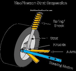
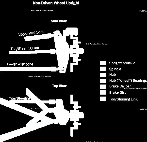
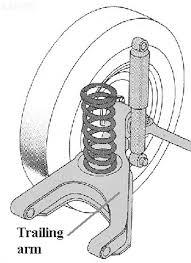

4 Common Suspension Types Double Wishbone Macpherson Strut Trailing Arm 4

5 Camber Angle The goal of camber is to keep the tire oriented perpendicular to the ground (maximize grip) during turning Lateral tire scrub is increased when you try to optimize camber angle in your suspension For solar cars, minimizing lateral scrub is arguably more important than optimizing camber for efficiency reasons Solar cars typically don t need to have great cornering capability at race car speeds 5
6 Caster Angle Positive caster helps with straight line tracking if the driver lets go of the steering wheel Adding caster also increases tire scrub when steering 6
7 Toe Angle Most efficient is zero toe Some toe in can help improve stability of vehicle at the cost of increased tire scrub 7

8 Scrub Radius True zero scrub radius is most efficient but can result in less stable steering feel On rear wheel drive cars, a positive scrub radius in the rear suspension can help improve straight line tracking when the steering wheel is released On the front, a slight negative scrub radius can help with maintaining stability in scenarios like sudden tire deflation or hitting standing water 8
9 Free Body Diagrams Draw free body diagrams for your various suspension components to calculate input loads Consider brake, bump, and steering loads 9
10 Fasteners Friction is not an acceptable method of constraining structural members Loctite is not allowed to restrain fasteners Make sure your frame can support suspension loads Try to put suspension/shock mount locations near structural nodes on the frame Minimize frame tube bending loads! No unrestrained fasteners are allowed in structural applications Flex lock nuts are OK Cotter/Spring Pins are OK Safety wire is OK 10

11 Rod Ends vs. Spherical Bearings Rod ends should not be put in bending If you do have to put the in bending, there is a rod end sizing calculation sheet on the ASC website that must be used! Consider spherical joints instead of rods ends 11
12 Suspension Adjustability The goal is to enable adjustability without resulting in binding or inefficient force path What to do with frame mounts to enable adjustability/account for manufacturing tolerances If you put a slot in the frame, make it perpendicular to the control arm link 12
13 Loads Into Nodes Efficient mechanical design can be used to minimize the weight components Minimize bending loads and if they must be used try to put them into components that can have a rectangular/oval cross section or ribs/gussets with extra bending strength 13


14 Eliminate Binding Don t over-constrain your suspension such that binding is possible What should stop vertical motion? - Rubber bump stops are built into shocks What should stop steering motion? - Steering bump stops ASC doesn t allow use of the pinion gear as the steering stop Must implement external steering stops that prevent the pinion gear from colliding Rubber steering stop is recommended 14
15 Ensure your suspension system has interference free travel through it s full range of vertical and steering motion To test this, take your spring off your shock absorber and manually move your suspension through it s extremes of vertical and steering travel The shock or steering bump stops should be the only things that ever interfere If you notice any other interference points that don t allow the bump stops to be engaged this interference needs to be eliminated by modifying your suspension components (grinding/redesign) Why does it matter? If you have hard metal to metal interference in your suspension travel this will result in grinding/wear stress concentrations and can put parts in bending that were not intended to be in bending resulting in premature failure 15

16 Rack & Pinion Steering 16
17 Other Notes Lower A-arms should be either the same length as or longer than uppers, and should have a nearly horizontal resting position. The upper arm should never be longer. Verify that your wheels spin freely Try to use retracting brake calipers Consider turning brake rotors on hub to be flat Steering shaft connections should be splined with a spring pin holding the tube on. In general, mountain bike components (shocks, brakes, etc.) are not sufficient for components for solar cars 17

18 Steering Ackermann steering Steering ratio Get a rack and pinion with a reasonable steering ratio - to sensitive to steering wheel movement will be difficult to control and not sensitive enough will make it difficult to complete the Scrutineering figure 8 test Ensure stable, reliable control of your vehicle Eliminate sources of steering slop Bump Steer Bump steer is where the front wheels turn when going over a bump To eliminate bump steer ensure your steering tie rod locations are lined up between your upper and lower suspension pivots as shown below 18
19 Open Discussion 19
Wheel Alignment And Diagnostic Angles (STE04)
") Module 1 Wheel Alignments Wheel Alignment And Diagnostic Angles (STE04) Wheel Alignments o Conditions Requiring An Alignment o Conditions Requiring An Alignment (cont d) o Why We Do Checks And Alignments
Module 1 Wheel Alignments Wheel Alignment And Diagnostic Angles (STE04) Wheel Alignments o Conditions Requiring An Alignment o Conditions Requiring An Alignment (cont d) o Why We Do Checks And Alignments
1. SPECIFICATIONS 2. WHEEL ALIGNMENT Front Suspension. (gas type) Rear Suspension. (gas type)
 Rear Suspension. (gas type)") 441101 053 1. SPECIFICATIONS Front Suspension Rear Suspension Description Suspension type Spring type Shock absorber type Stabilizer bar type Suspension type Spring type Shock absorber type Stabilizer
441101 053 1. SPECIFICATIONS Front Suspension Rear Suspension Description Suspension type Spring type Shock absorber type Stabilizer bar type Suspension type Spring type Shock absorber type Stabilizer
Design and Integration of Suspension, Brake and Steering Systems for a Formula SAE Race Car
 Design and Integration of Suspension, Brake and Steering Systems for a Formula SAE Race Car Mark Holveck 01, Rodolphe Poussot 00, Harris Yong 00 Final Report May 5, 2000 MAE 340/440 Advisor: Prof. S. Bogdonoff
1. SPECIFICATIONS 2. WHEEL ALIGNMENT
 441101 083 1. SPECIFICATIONS Front Suspension Rear Suspension Description Suspension type Spring type Shock absorber type Stabilizer bar type Suspension type Spring type Shock absorber type Stabilizer
WHY CHOOSE MOTOR TRIKE INDEPENDENT REAR SUSPENSION?
 WHY CHOOSE MOTOR TRIKE INDEPENDENT REAR SUSPENSION? WHY CHOOSE MOTOR TRIKE INDEPENDENT REAR SUSPENSION? NOT ALL INDEPENDENT REAR SUSPENSIONS (IRS) ARE CREATED EQUALLY. THIS IS WHY A BMW AND A HYUNDAI DON
APPENDIX A: Background Information to help you design your car:
 APPENDIX A: Background Information to help you design your car: Solar Cars: A solar car is an automobile that is powered by the sun. Recently, solar power has seen a large interest in the news as a way
2. Remove front wheels.
 Read all instructions before beginning work. Following instructions in the proper sequence will ensure the best and easiest installation. Thank you for purchasing Maximum Motorsports Caster/Camber Plates.
2. MEASURE VEHICLE HEIGHT. (b) Measure the vehicle height. Measurement points: C: Ground clearance of front wheel center
 Measure the vehicle height. Measurement points: C: Ground clearance of front wheel center") ADJUSTMENT If the wheel alignment has been adjusted, and if suspension or underbody components have been removed/installed or replaced, be sure to perform the following initialization procedure in order
ADJUSTMENT If the wheel alignment has been adjusted, and if suspension or underbody components have been removed/installed or replaced, be sure to perform the following initialization procedure in order
SUSPENSION 2-1 SUSPENSION TABLE OF CONTENTS
 DN SUSPENSION 2-1 SUSPENSION TABLE OF CONTENTS page ALIGNMENT... 1 FRONT SUSPENSION - 4x2... 6 page FRONT SUSPENSION - 4x4... 14 REAR SUSPENSION... 23 ALIGNMENT TABLE OF CONTENTS page AND OPERATION WHEEL
First, check and record the camber and caster readings, they will be adjusted later.
 First, check and record the camber and caster readings, they will be adjusted later. The caliper-mounting bosses are machined perpendicular to the spindle so they are an excellent place for the level.
Camber Angle. Wheel Alignment. Camber Split. Caster Angle. Caster and Ride Height. Toe Angle. AUMT Wheel Alignment
 AUMT 1316 - Wheel Alignment 11/15/11 Camber Angle Wheel Alignment Donald Jones Brookhaven College Camber Split Camber is the amount that the centerline of the wheel tilts away from true vertical when viewed
Typical mounting of a dial indicator for a radial check. Moog Automotive, Inc.
 Inspect / Service / Test / Replace To find out if the ball joint is loose beyond manufacturer's specifications, use an accurate measuring device. Most load carrying ball joints have a wear limit of 0.060"
ALIGNING A 2007 CADILLAC CTS-V
 ALIGNING A 2007 CADILLAC CTS-V I ll describe a four-wheel alignment of a 2007 Cadillac CTS-V in this document using homemade alignment tools. I described the tools in a previous document. The alignment
SUSPENSION 2-1 SUSPENSION TABLE OF CONTENTS
 XJ SUSPENSION 2-1 SUSPENSION TABLE OF CONTENTS page ALIGNMENT... 1 FRONT SUSPENSION... 7 page REAR SUSPENSION... 16 ALIGNMENT TABLE OF CONTENTS page AND WHEEL ALIGNMENT...1 DIAGNOSIS AND TESTING SUSPENSION
SuperQuest Salem Arms Best Practices
 SuperQuest Salem Arms Best Practices VEX Arm Designs Single 4-Bar 6-Bar 8-Bar Linear Slide Scissor Double Reverse 4-Bar Single Arms Arms These manipulators consist of a pivot point and at least 1 motor.
Design and optimization of Double wishbone suspension system for ATVs
 Design and optimization of Double wishbone suspension system for ATVs Shantanu Garud 1, Pritam Nagare 2, Rohit Kusalkar 3, Vijaysingh Gadhave 4, Ajinkya Sawant 5 1,2,3,4Dept of Mechanical Engineering,
Torque steer effects resulting from tyre aligning torque Effect of kinematics and elastokinematics
 P refa c e Tyres of suspension and drive 1.1 General characteristics of wheel suspensions 1.2 Independent wheel suspensions- general 1.2.1 Requirements 1.2.2 Double wishbone suspensions 1.2.3 McPherson
2004 SUSPENSION. Wheel Alignment - Corvette. Caster Cross +/ / Fastener Tightening Specifications Specification Application
 2004 SUSPENSION Wheel Alignment - Corvette SPECIFICATIONS WHEEL ALIGNMENT SPECIFICATIONS Wheel Alignment Specifications Camber Cross Caster Cross Suspension Camber Tolerance Caster Tolerance FE1 & FE3
Fundamentals of Steering Systems ME5670
 Fundamentals of Steering Systems ME5670 Class timing Monday: 14:30 Hrs 16:00 Hrs Thursday: 16:30 Hrs 17:30 Hrs Lecture 3 Thomas Gillespie, Fundamentals of Vehicle Dynamics, SAE, 1992. http://www.me.utexas.edu/~longoria/vsdc/clog.html
Part # Camber Caster Plates Ford Mustang All Ford Mustang GT500
 Part # 24220 Camber Caster Plates 2005-2010 Ford Mustang All 2007-2014 Ford Mustang GT500 J&M Products once again outdoes our competitors with these fully adjustable (Protected under US Patent No. 8,820,759
RZR XP 1000 HD Radius Rod Kit
 RZR XP 1000 HD Radius Rod Kit Polaris RZR XP 1000 2014-2016 Part #: 5201509 Rev. 111517 491 W. Garfield Ave., Coldwater, MI 49036. Phone: 517-278-7768 E-mail: sales-rtpro@sporttruckusainc.com SAFETY WARNING
PRESEASON CHASSIS SETUP TIPS
 PRESEASON CHASSIS SETUP TIPS A Setup To-Do List to Get You Started By Bob Bolles, Circle Track Magazine When we recently set up our Project Modified for our first race, we followed a simple list of to-do
MM Caster/Camber Plates, (MMCC7989)
") 3430 Sacramento Dr., Unit D San Luis Obispo, CA 93401 Telephone: 805/544-8748 Fax: 805/544-8645 www.maximummotorsports.com MM Caster/Camber Plates, 1979-89 (MMCC7989) IMPORTANT: The bearing used in our
3430 Sacramento Dr., Unit D San Luis Obispo, CA 93401 Telephone: 805/544-8748 Fax: 805/544-8645 www.maximummotorsports.com MM Caster/Camber Plates, 1979-89 (MMCC7989) IMPORTANT: The bearing used in our
SECTION 2C FRONT SUSPENSION TABLE OF CONTENTS
 SECTION 2C FRONT SUSPENSION TABLE OF CONTENTS Description and Operation... 2C-2 Front Suspension... 2C-2 Specifications... 2C-4 Component Locator... 2C-5 Front Suspension Assembly... 2C-5 Cross-Sectional
SAE Mini BAJA: Suspension and Steering
 SAE Mini BAJA: Suspension and Steering By Zane Cross, Kyle Egan, Nick Garry, Trevor Hochhaus Team 11 Progress Report Submitted towards partial fulfillment of the requirements for Mechanical Engineering
Vehicle Level Steering and Suspension Alignment Service and Repair Wheel Alignment. Wheel Alignment
 Page 1 of 7 2002 Dodge Truck Caravan FWD V6-3.3L VIN R Vehicle Level Steering and Suspension Alignment Service and Repair Wheel Alignment Wheel Alignment PRE-WHEEL ALIGNMENT INSPECTION Before any attempt
2005-Pres. Ford Mustang Camber Plate Installation Instructions:
 2005-Pres. Ford Mustang Camber Plate Installation Instructions: J&M Products once again outdoes our competitors with these fully adjustable PATENT PENDING Camber & Caster plate assemblies for the 2005-2010
Signature redacted. Signature redacted- - JUL LIBRARIES
 Design and Analysis of the Front Suspension Geometry and Steering System for a Solar Electric Vehicle by Bruce Arensen Submitted to the Department of Mechanical Engineering in Partial Fulfillment of the
Why do cars need Alignment
 Why do cars need Alignment The main purpose of wheel alignment is to make the tires roll without Scuffing, slipping, or dragging under all operating conditions. Caster Camber Toe Steering axis inclination
SUSPENSION 2-1 SUSPENSION CONTENTS
 DN SUSPENSION 2-1 SUSPENSION CONTENTS page ALIGNMENT... 1 FRONT SUSPENSION... 5 page REAR SUSPENSION... 13 ALIGNMENT INDEX page GENERAL INFORMATION WHEEL ALIGNMENT... 1 DIAGNOSIS AND TESTING PRE-ALIGNMENT
Design and Analysis of suspension system components
 Design and Analysis of suspension system components Manohar Gade 1, Rayees Shaikh 2, Deepak Bijamwar 3, Shubham Jambale 4, Vikram Kulkarni 5 1 Student, Department of Mechanical Engineering, D Y Patil college
GR40 SLA Installation and Set Up Instructions.
 GR40 SLA Installation and Set Up Instructions. Read these instructions completely before beginning. These instructions are written for experienced installer/technicians with a strong idea as to how a chassis
Next, set the bar level and tighten it down. Do this on both the driver and passenger sides.
 Next, set the bar level and tighten it down. Do this on both the driver and passenger sides. Using two tape measures, measure the outside width at the front and the rear of the tubes. The front dimension
GENERAL INFORMATION. Wheel Alignment Theory & Operation
 Fig. 1: Checking Steering Linkage GENERAL INFORMATION Wheel Alignment Theory & Operation ADJUSTMENTS NOTE: This article is intended for general information purposes only. This information may not apply
Kinematic Analysis of Roll Motion for a Strut/SLA Suspension System Yung Chang Chen, Po Yi Tsai, I An Lai
 Kinematic Analysis of Roll Motion for a Strut/SLA Suspension System Yung Chang Chen, Po Yi Tsai, I An Lai Abstract The roll center is one of the key parameters for designing a suspension. Several driving
STEERING SYSTEM Introduction
 STEERING SYSTEM Introduction The steering makes it possible to change direction. The steering must be reliable and safe; there must not be too much play in the steering. It must be possible to steer accurately.
ATASA 5 th. Wheel Alignment. Please Read The Summary. ATASA 5 TH Study Guide Chapter 47 Pages: Wheel Alignment 64 Points
 ATASA 5 TH Study Guide Chapter 47 Pages: 1403 1423 64 Points Please Read The Summary Before We Begin Keeping in mind the Career Cluster of Transportation, Distribution & Logistics Ask yourself: What careers
SUSPENSION 2-1 SUSPENSION CONTENTS
 ZJ SUSPENSION 2-1 SUSPENSION CONTENTS page ALIGNMENT... 1 FRONT SUSPENSION... 6 page REAR SUSPENSION... 14 ALIGNMENT INDEX page GENERAL INFORMATION WHEEL ALIGNMENT... 1 DIAGNOSIS AND TESTING SUSPENSION
ROLL CENTER You can adjust the front and rear roll centers of the XB8 by changing the mounting locations of various components.
 Your XRAY XB8 luxury nitro buggy is a top competition, precision racing machine that features multiple adjustments that allow you to set up for any track condition. The XB8 includes innovative set-up features
CHASSIS DYNAMICS TABLE OF CONTENTS A. DRIVER / CREW CHIEF COMMUNICATION I. CREW CHIEF COMMUNICATION RESPONSIBILITIES
 CHASSIS DYNAMICS TABLE OF CONTENTS A. Driver / Crew Chief Communication... 1 B. Breaking Down the Corner... 3 C. Making the Most of the Corner Breakdown Feedback... 4 D. Common Feedback Traps... 4 E. Adjustment
INSTRUCTION S G-Comp Front Suspension: Chevy Camaro Speedway Motors, Inc Kit Contents:
 INSTRUCTION S 350-500 G-Comp Front Suspension: 70-81 Chevy Camaro Speedway Motors, Inc. 2017 Kit Contents: 350500.1 G-Comp Subframe, Camaro 350500.2 G-Comp Sway Bar Kit, Camaro 350500.3 Hardware Kit, G-Comp
Tech Tip: Trackside Tire Data
 Using Tire Data On Track Tires are complex and vitally important parts of a race car. The way that they behave depends on a number of parameters, and also on the interaction between these parameters. To
INSTALLATION GUIDE TCP RCKM-01
 READ ALL INSTRUCTIONS COMPLETELY AND THOROUGHLY UNDERSTAND THEM BEFORE DOING ANYTHING. CALL TOTAL CONTROL PRODUCTS TECH SUPPORT (916) 388-0288 IF YOU NEED ASSISTANCE. INSTALLATION GUIDE TCP RCKM-01 Manual
QuickTrick Alignment Tools
 QuickTrick Alignment Tools QuickTrick Alignment Kits are Professional quality tools designed for a lifetime of reliable service. QuickTrick Kits can be used on any vehicle for measurement of the alignment
COWBOY MOTORSPORTS SENIOR DESIGN Scott Dick Garrett Dollins Logan Gary
 COWBOY MOTORSPORTS SENIOR DESIGN 2016-2017 Scott Dick Garrett Dollins Logan Gary 2016-2017 ASABE INTERNATIONAL QUARTER SCALE TRACTOR STUDENT DESIGN COMPETITION COMPETITION OVERVIEW Design report 500 pts
1 of 12 8/25/2017, 4:29 PM
 1 of 12 8/25/2017, 4:29 PM STANDARD PROCEDURE - WHEEL ALIGNMENT PRE-WHEEL ALIGNMENT INSPECTION Before any attempt is made to change or correct the wheel alignment, the following inspection and necessary
How to Set the Alignment on Ford Mustangs
 How to Set the Alignment on 1967-1973 Ford Mustangs Let's Get This Straight - Mustang Monthly Magazine Christopher Campbell Technical Editor March 25, 2015 Frontend alignment is one of the most basic adjustments
Unit 3. The different types of steering gears are as follows:
 Steering Gears One of the important human interface systems in the automobile is the steering gear. The steering gear is a device for converting the rotary motion of the steering wheel into straight line
Next, chase the threads in the lower A-arm mounts with the 5/8-18 tap and blowout any remaining particles.
 Next, chase the threads in the lower A-arm mounts with the 5/8-18 tap and blowout any remaining particles. Now, apply some anti-seize to the threads of the pivot stud. Also put anti-seize inside the bore
SAE Mini BAJA: Suspension and Steering
 SAE Mini BAJA: Suspension and Steering By Zane Cross, Kyle Egan, Nick Garry, Trevor Hochhaus Team 11 Project Progress Submitted towards partial fulfillment of the requirements for Mechanical Engineering
SUSPENSION. Front - Corvette
 1998-99 SUSPENSION Front - Corvette DESCRIPTION The major suspension components are made of high-strength, lightweight, forged aluminum alloy. A fiberglass single-leaf spring is mounted transversely below
DRIVE-CONTROL COMPONENTS
 3-1 DRIVE-CONTROL COMPONENTS CONTENTS FRONT SUSPENSION................... 2 Lower Arms............................... 5 Strut Assemblies........................... 6 REAR SUSPENSION.....................
US Patent You will find many features that set our Caster/Camber Plates apart from the rest.
 3430 Sacramento Dr., Unit D San Luis Obispo, CA 93401 Telephone: 805/544-8748 Fax: 805/544-8645 www.maximummotorsports.com US Patent 6485223 Read all instructions before beginning work. Following instructions
SUMMARY OF STANDARD K&C TESTS AND REPORTED RESULTS
 Description of K&C Tests SUMMARY OF STANDARD K&C TESTS AND REPORTED RESULTS The Morse Measurements K&C test facility is the first of its kind to be independently operated and made publicly available in
II YEAR AUTOMOBILE ENGINEERING AT AUTOMOTIVE CHASSIS QUESTION BANK UNIT I - LAYOUT, FRAME, FRONT AXLE AND STEERING SYSTEM
 II YEAR AUTOMOBILE ENGINEERING AT 6402 - AUTOMOTIVE CHASSIS QUESTION BANK UNIT I - LAYOUT, FRAME, FRONT AXLE AND STEERING SYSTEM 1. Write about the requirements of frame and selection of cross section
SUSPENSION 2-1 SUSPENSION CONTENTS
 TJ SUSPENSION 2-1 SUSPENSION CONTENTS page ALIGNMENT... 1 FRONT SUSPENSION... 5 page REAR SUSPENSION... 12 ALIGNMENT INDEX page GENERAL INFORMATION WHEEL ALIGNMENT... 1 DIAGNOSIS AND TESTING SUSPENSION
Wheel Alignment Fundamentals
 CHAPTER 67 Wheel Alignment Fundamentals OBJECTIVES Upon completion of this chapter, you should be able to: Describe each wheel alignment angle. Tell which alignment angles cause wear or pull. KEY TERMS
SUSPENSION 2-1 SUSPENSION CONTENTS
 TJ SUSPENSION 2-1 SUSPENSION CONTENTS page ALIGNMENT... 1 FRONT SUSPENSION... 6 page REAR SUSPENSION... 13 ALIGNMENT INDEX page DESCRIPTION AND OPERATION WHEEL ALIGNMENT... 1 DIAGNOSIS AND TESTING SUSPENSION
INSTALLATION GUIDE Bolt-On Drag-Race Strut Clip Chevy II
 INSTALLATION GUIDE 7702 Bolt-On Drag-Race Strut Clip 1962-67 Chevy II Description: STRUT CLIP 4130 BOLT ON 62-67 CHEVY II, INCLUDES 4130 ROUND TUBE FRAME CLIP, DOUBLE-ADJUSTABLE STRUTS, ADJUSTABLE-HEIGHT
Chevy Nova Pro-Touring Front Suspension Installation Instructions
 1962-1967 Chevy Nova Pro-Touring Front Suspension Installation Instructions 1-800-984-6259 www.totalcostinvolved.com 1 Pro-Touring Clip A-Arm Assembly Sway Bar Assembly Fender Panel Kit 8 7/16-20 * 1 ¼
TIPS TO FINAL ASSEMBLY Radio installation. The Electronic speed control (ESC) and the receiver need to be mounted onto the chassis, using double sided
 and the receiver need to be mounted onto the chassis, using double sided") TIPS TO FINAL ASSEMBLY Radio installation. The Electronic speed control (ESC) and the receiver need to be mounted onto the chassis, using double sided tape (not supplied.) Mount the ESC first on the chassis
TIPS TO FINAL ASSEMBLY Radio installation. The Electronic speed control (ESC) and the receiver need to be mounted onto the chassis, using double sided tape (not supplied.) Mount the ESC first on the chassis
Wheel Alignment Defined
 Wheel Alignment Defined While it's often referred to simply as an "alignment" or "wheel alignment," it's really complex suspension angles that are being measured and a variety of suspension components
Installation Instructions
 Installation Instructions Eibach Springs, Inc. 264 Mariah Circle Corona, California 92879-1751 USA Tech Support 800-222-8811 Ext 114 Eibach Pro Street Coilovers - #8598.711 2006-2008 Volkswagen, GTi, 2.0L
Cane Creek Double Barrel Instructions
 Cane Creek Double Barrel Instructions Congratulations on your purchase of the Cane Creek Double Barrel rear shock. Developed in partnership with Öhlins Racing, the Double Barrel brings revolutionary suspension
Global West Suspension 655 South Lincoln Ave San Bernardino Ca Phone Fax Web address globalwest.
 Global West Suspension 655 South Lincoln Ave San Bernardino Ca. 92408 Phone 877-470-2975 Fax 909-890-0703 Web address globalwest.net Mustang coilover instruction sheets for 64-66 Kit includes the following
ASSOCIATED 1:10 SCALE ELECTRIC BUGGY INSTRUCTION MANUAL FOR THE TEAM ASSOCIATED RC10B Associated Electrics, Inc. RS-1
 ASSOCIATED 1:10 SCALE ELECTRIC BUGGY INSTRUCTION MANUAL FOR THE TEAM ASSOCIATED RC10B4 TT RS-1 2003-2006 Associated Electrics, Inc. FINAL ADJUSTMENTS RADIO ADJUSTMENTS Use the following
INSTALLATION GUIDE. TCP TIER-14 Bump Steer Conversion Kit - Early Mustang to Late Spindle
 READ ALL INSTRUCTIONS COMPLETELY AND THOROUGHLY UNDERSTAND THEM BEFORE DOING ANYTHING. CALL TOTAL CONTROL PRODUCTS TECH SUPPORT (916) 388-0288 IF YOU NEED ASSISTANCE. INSTALLATION GUIDE TCP TIER-14 Bump
A double-wishbone type suspension is used in the front. A multi-link type suspension is used in the rear. Tread* mm (in.) 1560 (61.
 1560 (61.") CHASSIS SUSPENSION AND AXLE CH-69 SUSPENSION AND AXLE SUSPENSION 1. General A double-wishbone type suspension is used in the front. A multi-link type suspension is used in the rear. 08D0CH111Z Specifications
CHASSIS SUSPENSION AND AXLE CH-69 SUSPENSION AND AXLE SUSPENSION 1. General A double-wishbone type suspension is used in the front. A multi-link type suspension is used in the rear. 08D0CH111Z Specifications
Front Suspension Redo
 Front Suspension Redo Message: First, thanks to all the previous posters for guidance in my doing the suspension. As thanks, here s the updated document for doing the front suspension. Procedure: While
Brake, suspension and side slip testers... the facts! October 2009 Technical Newsletter
 October 2009 Technical Newsletter Brake, suspension and side slip testers... the facts! VTEQ brake test lane at Jim Wright Nissan AECS Ltd is the NZ distributor of the VTEQ test equipment since 2001. AECS
QUICKTRICK PRODUCT IN- STRUCTIONS ALIGNMENT SIMPLE SOLUTIONS. Mr & Mrs QuickTrick. Made in the USA
 QUICKTRICK PRODUCT IN- ALIGNMENT SIMPLE SOLUTIONS Thank you for your support of QuickTrick products. You are supporting an American Dream business grown from the Garage and the race track to a World Wide
Dynamic Analysis of Double Wishbone and Double Wishbone with S Link + Toe Link
 RESEARCH ARTICLE OPEN ACCESS Dynamic Analysis of Double Wishbone and Double Wishbone with S Link + Toe Link Rajkumar Kewat, Anil Kumar Kundu,Kuldeep Kumar,Rohit Lather, Mohit Tomar RJIT, B.S.F ACADEMY
IRS-151 INSTALLATION INSTRUCTIONS `55-57 CHEVY INDEPENDENT REAR SUSPENSION
 IRS-151 INSTALLATION INSTRUCTIONS `55-57 CHEVY INDEPENDENT REAR SUSPENSION Please read these instructions completely before starting your installation. Remember the basic rule for a successful installation:
DIAGNOSIS AND TESTING
 DIAGNOSIS AND TESTING SUSPENSION AND STEERING SYSTEM 2007 SUSPENSION Suspension - Nitro CONDITION POSSIBLE CAUSES CORRECTION FRONT END NOISE 1. Loose or worn wheel bearings. 1. Replace wheel bearings.
ACE 325/570 2 Lift Kit
 ACE 325/570 2 Lift Kit Polaris Ace 325/570 2014+ Part #: 5101244 Rev. 082316 491 W. Garfield Ave., Coldwater, MI 49036. Phone: 517-278-7768 E-mail: sales-rtpro@sporttruckusainc.com SAFETY WARNING RT Pro
After Installing an Öhlins Shock Absorber/Front Fork
 Checkpoint Öhlins After Installing an Öhlins Shock Absorber/Front Fork Note! All motorcycles are designed with a suspension geometry that includes height and fork angle. Changing components (for example
Eibach Pro-System-Plus
 Eibach Pro-System-Plus Tools : - Floor Jack - 3 Jack Stands (4 preferred) - 2 wheel stoppers - Car wrench set - Fire torch - Bolt thread locker (use on every bolt you tight) Disclaimer: This guide is not
UNIBODY/FRAME/WHEEL ALIGNMENT II ABCT 2212
 UNIBODY/FRAME/WHEEL ALIGNMENT II ABCT 2212 A. Course Description Credits: 6.00 Lecture Hours/Week: 1.00 Lab Hours/Week: 5.00 OJT Hours/Week: 0 Prerequisites: None Corequisites: None MnTC Goals: None This
2005 to 2008 #08 Metric Nova Chassis Set Up Sheet
 Springs 1 2005 to 2008 #08 Metric Nova Chassis Set Up Sheet Flat end of spring down on tubular lower a-arms. Left Front 800lb. Right Front 750lb. Left Rear 200lb. Right Rear 225lb. On Top of Tube Axle
SUSPENSION 2-1 SUSPENSION CONTENTS
 WJ SUSPENSION 2-1 SUSPENSION CONTENTS page ALIGNMENT... 1 FRONT SUSPENSION... 4 page REAR SUSPENSION... 15 ALIGNMENT INDEX page AND WHEEL ALIGNMENT... 1 SERVICE PROCEDURES PRE-ALIGNMENT... 2 AND WHEEL
Installation Procedure GR40 S197 SLA Front Suspension System (Does not include Aluminum Spindle and Hub Instructions)
") Installation Procedure GR40 S197 SLA Front Suspension System (Does not include Aluminum Spindle and Hub Instructions) Please take the time and read these instructions first! The GR40 S197 system is designed
Installation Procedure GR40 S197 SLA Front Suspension System (Does not include Aluminum Spindle and Hub Instructions) Please take the time and read these instructions first! The GR40 S197 system is designed
Multilink IRS Setup & Assembly Manual
 Art Morrison Enterprises Multilink IRS Setup & Assembly Manual 8/13/2018 Rev 6 Contents Introduction... 3 Toe Link Eccentric... 3 Powdercoating... 3 IRS Assembly Steps... 4 1. Backing plates/knuckles/hubs...
OTK CHASSIS- SET UP GUIDE
 OTK CHASSIS- SET UP GUIDE Introduction This setup guide is created to facilitate a user of OTK equipment to reach an optimal chassis setup and on-track performance. The different tuning possibilities and
ON ROAD SETUP GUIDE PART ONE
 PART ONE Ride height is adjusted by the preload of the spring collars. Winding them down will raise the ride height, while winding them up will decrease the ride height. It is important to note that adjusting
Part # GM G Body Air Suspension System
 350 S. St. Charles St. Jasper, In. 47546 Ph. 812.482.2932 Fax 812.634.6632 www.ridetech.com Part # 11320298 78-88 GM G Body Air Suspension System Front Components: 1 11323001 HQ Series Front Shockwaves
BASIC WHEEL ALIGNMENT
 BASIC WHEEL ALIGNMENT You have got to know all the angles. Correct wheel alignment plays a huge part in a customer s positive driving experience. Having it dialed in correctly is essential to proper vehicle
 www.whiteline.com.au ROCK ROLL CENTRE KIT ESSENTIAL FOR LOWERED VEHICLES Recommended for race use only WHITELINE diagnosed a mediocre MacPherson front suspension with poor roll centre control and excessive
FRONT WHEEL ALIGNMENT
 2 Front: B A A Rear: C D Front SUENSION FRONT WHEEL ALIGNMENT D F046082E03 B FRONT WHEEL ALIGNMENT ADJUSTMENT 1. INECT TIRE (a) Inspect the tires (see page TW-3). 2. MEASURE VEHICLE HEIGHT Standard vehicle
along with standard XT2 Instruction Manual and also XT2 18 Supplementary Sheet.
 Use this XT2 Dirt Conversion Supplementary Sheet along with standard XT2 Instruction Manual and also XT2 18 Supplementary Sheet. Parts included in Bag 8: 303141 SHIM 3x5x1.0MM (10) 322111 XT2 COMPOSITE
2. Remove front wheels.
 1 PARTS DIAGRAM 2 Installation Instructions: (PASSENGER SIDE) 1. Place jack under center of RUV front end and lift until front wheels clear the ground. Be careful to support the RUV properly so that it
EagleMotorsports.com Dear Valued Customer,
 Dear Valued Customer, Thank you for choosing the Stallard brand and establishing this partnership. We appreciate the opportunity to assist you and look forward to promoting your future success. The staff
2011+ Adjustable Tie-rod Ends (Mm5TR-2)
") 3430 Sacramento Dr., Unit D San Luis Obispo, CA 93401 Telephone: 805/544-8748 Fax: 805/544-8645 www.maximummotorsports.com 2011+ Adjustable Tie-rod Ends (Mm5TR-2) Instructions 1. Set the parking brake
3430 Sacramento Dr., Unit D San Luis Obispo, CA 93401 Telephone: 805/544-8748 Fax: 805/544-8645 www.maximummotorsports.com 2011+ Adjustable Tie-rod Ends (Mm5TR-2) Instructions 1. Set the parking brake
TC35160 & TC35270 Operation Manual & Installation Instructions
 Please visit www.blueox.com for the latest version of these installation instructions. TC35160 & TC35270 Operation Manual & Installation Instructions Serial Number Blue OX One Year Limited Warranty 292-6090
WARNING: the engine does not come with oil in it. Please fill the oil before starting. The 200cc hardknock requires 9/10 of a quart of oil.
 WARNING: the engine does not come with oil in it. Please fill the oil before starting. The 200cc hardknock requires 9/10 of a quart of oil. Things needed for assembly. -2 tubes of blue loc-tite. I don
2011 MKS Workshop Manual. SECTION : Suspension System - General Information DESCRIPTION AND OPERATION Procedure revision date: 05/25/2010
 SECTION 204-00: Suspension System - General Information 2011 MKS Workshop Manual DESCRIPTION AND OPERATION Procedure revision date: 05/25/2010 Wheel Alignment Angles Camber Negative and Positive Camber
#0980 Intimidator 7 Direct Drive Racing Kit
 #0980 Intimidator 7 Direct Drive Racing Kit 1 Thank you for purchasing the Intimidator 7! Within this kit you will find a race winning car with over 30 years of Custom Works design and quality. The latest
USE THE PARTS LIST BELOW TO MAKE SURE YOUR KIT IS COMPLETE BEFORE INSTALLATION. IF ANY PIECES ARE MISSING, PLEASE CONTACT:
 1962-1967 Chevy Nova Pro-Touring Front Suspension Installation Instructions Tech line: 1-855-693-1259 www.totalcostinvolved.com Read and understand these instructions before starting any work! USE THE
Maximum Motorsports Camber Caster Plates (05-10):
:") Maximum Motorsports Camber Caster Plates (05-10): Tools Required: Lug Wrench 21mm Deep Socket 18mm Deep Socket 15mm Deep Socket 17mm Socket 13mm Socket 10mm Socket Torque Wrench (requires 166lb-ft capacity
Maximum Motorsports Camber Caster Plates (05-10): Tools Required: Lug Wrench 21mm Deep Socket 18mm Deep Socket 15mm Deep Socket 17mm Socket 13mm Socket 10mm Socket Torque Wrench (requires 166lb-ft capacity
INSTALLATION INSTRUCTIONS
 INSTALLATION INSTRUCTIONS REAR DISC BRAKE CONVERSION KIT A125-3 1965-72 GM A-BODY 10 & 12 BOLT AXLES Thank you for choosing STAINLESS STEEL BRAKES CORPORATION for your braking needs. Pleases take the time
AMT Motorsport C7 Corvette Camber Kit User s Guide. 8 Upper Control Arm Studs and hardware for rear upper control arm adjustments
 AMT Motorsport C7 Corvette Camber Kit User s Guide Thank you for purchasing the AMT Motorsport Camber Kit for the C7 Corvette. We believe this is the most versatile camber kit available on the market,