QJY245DS~DA. Two Post Lift Installation & Adjustment Manual
|
|
|
- Audra Peters
- 5 years ago
- Views:
Transcription

1 QJY245DS~DA Two Post Lift Installation & Adjustment Manual
2 Table of Contents 1. Warning 2 2. Summary 2 3. Use 2 4. Mainly technology parameter 2 5. Basic structure of the production 3 6. Safety device 4 7. Installation and adjustment Important notice Base plate layout install the powerside column install and adjust the balancing steel cable install the power unit and hydraulic line Adjust the steel chain Install the insurance and insurance wire rope Lift adjustment preparation before the adjustment Adjustment procedure Failure and repair Diagram of the hydraulic system 13 The manufacturer reserves the right to make design changes or add improvements to its product line without notice. 1
3 1. Warning This manual is an essential integral part of this equipment. Please read it carefully. Properly keep this manual for use during the maintenance. This lift is only used for its clearly designated purpose. Never use it for other purpose. The manufacturer is not responsible for any damage or injury caused by improper use for other purpose. 2. Summary The lift double-cylinder hydraulic lifter is a new type of hydraulic drive vehicle elevator equipment by our company recently. It is designed briefly and reasonably. It select hydraulic power unit, having merits of low noise, smooth rise-and fall. The machine has elevator carriage, safety device guard against falling, qualification equipment for ultimate load, lock equipment of revolution angle of lift arm, and the forced same step of the steel wires of elevator carriage. Lower elevator carriage makes it have strong flexibility and convenient operation.it is the necessary elevator equipment in the vehicle industry. 3. Use The machine can be use in elevating saloon car, beach wagon, and station wagon, which have lower than 4500kg deadweight. It fixes them at operational height needed in order to repair, service and clean. 4. Mainly technology parameter Model Lift quality Lift height Rise time Fall time Power of motor Power supply Drive Thru Clearance Machine weight QJY245DS 4.5t 1990mm <50s >45s 2.2kw 380/220v 2658mm 760kg QJY245DA 4.5t 1990mm <50s >45s 2.2kw 380/220v 2583mm 765kg NOTE: If use 220V power supply, the user should buy a manostat. Please choose the correct power supply, or will cause damage to your lift or injury to you. Customers should response for the damage caused by the unstable voltage. 2
4 5. Basic structure of the production The machine mainly has double-column, double oil cylinders, hydraulic power unit, elevating carriage in-step equipment, safety mechanism, and rotation-angle lock equipment of lift arm which can be operated simply.(as shown in Fig.1) When you push the switch on the electric motor of hydraulic power unit, the machine will rise. If you loosen, it will stop. If you want to go down, you must pull the safety unlocked wire to apart the safety bracing plate from the safety seat firstly, and open the handle bar on the hydraulic power unit. Gyration lift arm is telescopic and rotatable. Height of pallet can be adjusted in order to meet the different need of different kinds of vehicle. Lock devices are installed on the four lift arms in order to lock automatically at arm angle work need. When carriage is at the bottom, lift arm can rotate freely. 3
5 Fig.1 6. Safety device The machine has safety device guard against crack falling no-pressure protection defending oil pipe overload. (as shown in Fig.2) Safety bracing plates are designed on the left and right lift carriages. when lift pallet rise, safety bracing plate dragged by spring jumps in the safety block of pole. When stop the rise, safety-bracing plate dragged by spring is on the safety block and defends carriage falling. If the carriage would fall, crawling the hydraulic switch make the carriage rise a little firstly. Then draw the unlocked line on the left and right carriage in order to draw safety bracing apart from safety seat. Last, open the pressure relief valve on the hydraulic pump to make the carriage fall. 4

6 Fig.2 5
7 7. Installation and adjustment 7.1 Important notice The wrong installation will cause the lift damage or personal injury. The manufacturer will not undertake any responsibilities for any damage caused due to incorrect installation and usage of this equipment, whether directly or indirectly. The correct installation location shall be horizontal floor to ensure the horizontal lifting. The slightly slope floor can be corrected by proper shimming. The thickness of shims shouldn t exceed 5mm. Don t install the lift on any asphalt or any surface other concrete floor conforming to the minimum requirement showed in this manual. Don t install the lift on the concrete with seams or crack and defect. Please check together with the architect. Concrete drilling test: The installation personnel can test the concrete thickness at each site by drilling test. If several lifts are installed at one place, it is preferred to make drilling test in each site. 7.2 Base plate layout QJY245DS QJY245DS Fig.3 6
8 7.3 install the powerside column First connect and assemble the powerside column, and then raise the powerside column upper right to the location. Align the base plate of column with the chalk line layout. Guided by the hole on the base plate of the column, drilling the holes into the concrete slab and use six concrete anchor bolts to fix it into the ground. During the drilling process, ensure no movement from the chalk line.(as shown in Fig.4) To get the correct and safety installation, please follow the following installation steps. 1. Wear the safety goggles. 2. Use hard alloy drill-bit. 3. Don t use the drill-bit with wearing exceeding the tolerance. 4. The drill and concrete surface should be kept perpendicular. 5. Let the drill work itself. Don t apply the extra force, and don t ream the hole or allow the drill to wobble. 6. The drilling depth of the hole is based on the length of anchor bolt. The distance from the bolt head to the concrete floor should be more than twice of the bolt diameter. 7. Remove the dust from the hole. 8. Gently tap the bolt into the hole till the washer rests against the base plate of column. 9. Tighten the bolt. Fig.4 7
, and two carriages are in equal position from the floor (same height). Install the two steel cables as shown in Fig.5.")
9 7.4 install and adjust the balancing steel cable Rise the two carriages to the safety locking position (make sure that the safety locks on each column are fully engaged before attempting to install cables), and two carriages are in equal position from the floor (same height). Install the two steel cables as shown in Fig.5. Adjust the tension of cables through the adjustment nuts on each end of steel cable. The steel cables should be in equal tension. Each steel cable should be ensured in the pulley when adjusting tightly, otherwise the steel cable will be damage 8


10 Fig Install the power unit and hydraulic line Use two M10 bolts and washers to fix the power unit as shown in Fig.6,install the hydraulic line, and tighten all the fittings to prevent oil leakage. Fill the reservoir with hydraulic oil (oil capacity of 10L).operate carefully to avoid dust and other pollutants mixed with the hydraulic oil. 9


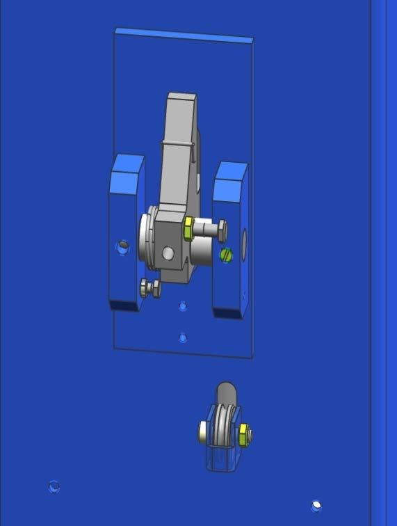
11 Fig Install the beam and Limit switch (Fig.7) Fig.7 10


 Fig.")
 Fig.")
12 7.7 Install the insurance and insurance wire rope The insurance of the power side column (Fig.8) Fig.8 The insurance of the off-side column (Fig.9) Fig.9 11
13 8. Lift adjustment 8.1 preparation before the adjustment lubricate contact surface of the carriage and corners of column with general-purpose lithium grease. All sliding surface should be coated evenly from top to bottom. Fill hydraulic oil N32or N46 to the oil reservoir of the power unit. 8.2 Adjustment procedure Check to see if the power supply is installed properly. Check to see if all the bolts are fastened. Press the UP button to start the motor, and the carriage rise. Release the UP button, and the carriage stops. To lower the carriage, first draw the unlocked line on the left and right carriage. If it can t release the safeties, press the UP button again, then draw the unlocked line, then press the DOWN button, the carriage will lower. Release the DOWN button,the carriage will stop lowering. When the vehicle is raised at required height, press the DOWN button, making sure the safety locked. Ensure the safe repairing under the vehicle. The hydraulic system may contain air due to new installation. To bleed the air, repeat the lifting and lowering for several times. The adjustment is completed. 12
14 9. Failure and repair Failures Reasons Recovery methods Electric appliance fail, can t start Carriage crawl during rising Carriage can t fall or fall unwell-balanced Electric source phase lack or electric appliance failure Air existing in the hydraulic system or oil lack in oil tank Operation mistake without pull the safety apart Check resource, fuse box, contactor in connection box of electric machine Pour oil into tank, oil cylinder run total excursion some times or discharge the air in the oil tank Scrawl the switch to elevate the carriage a little and open pressure relief valve for falling after pall off the safety hook to make it run well 10.Diagram of the hydraulic system
15 14

16 QJY245DS Parts List 15
17 16

18 QJY245DA Parts List 17
Power of motor (KW) Power supply(v) Please note that if you use 220V power supply, you need to have a manostat.
 Power supply(v) Please note that if you use 220V power supply, you need to have a manostat.") Ⅰ. Introduction 1. Abstract The double-cylinder hydraulic lift is a hydraulic drive vehicle lift equipment developed by our company. It is designed briefly and reasonable. It select hydraulic power unit,
Ⅰ. Introduction 1. Abstract The double-cylinder hydraulic lift is a hydraulic drive vehicle lift equipment developed by our company. It is designed briefly and reasonable. It select hydraulic power unit,
INSTALLATION MANUAL. Table of Contents
 INSTALLATION MANUAL Table of Contents. Precaution. Structure and working Principle... Structure Schematic Diagram..... Main Structure and Principle of the Equipment.3 3. Tools for installation and adjustment..4
USE AND MAINTENANCE MANUAL
 USE AND MAINTENANCE MANUAL ELECTRO-HYDRAULIC 2-POST LIFT AL-10F AL-10C WARNING This instruction manual is an essential integral part of this product. Please read all instructions. Properly keep this manual
CONTENTS. Product Features and Specifications...1. Installation Requirement...3. Steps of Installation...4. Exploded View Test Run...
 TP10AS 2-POST LIFT CONTENTS Product Features and Specifications...1 Installation Requirement...3 Steps of Installation...4 Exploded View...24 Test Run....28 Operation Instruction...29 Maintenance...30
Read this entire manual before operation begins.
 Read this entire manual before operation begins. Record below the following information which is located on the serial number data plate. Serial No. Model No. Date of Installation Contents Specifications.............
LAUNCH TLT240SB. Two Post Lift User s Manual. Version No: 1604
 LAUNCH TLT240SB Two Post Lift User s Manual Version No: 1604 WARNING This instruction manual is an essential integral part of this product. Please read all instructions. Properly keep this manual for use
CONTENTS. Product Features and Specifications Installation Requirement Installation Exploded View Operation Instruction...
 1 CONTENTS Product Features and Specifications... 3 Installation Requirement... 5 Installation... 6 Exploded View... 20 Test... 22 Operation Instruction... 25 Maintenance... 26 Trouble Shooting... 27 Parts
Read this entire manual before operation begins.
 Read this entire manual before operation begins. Record below the following information which is located on the serial number data plate. Serial No. Model No. Date of Installation Contents Specifications.............
Read this entire manual before operation begins.
 Read this entire manual before operation begins. Record below the following information which is located on the serial number data plate. Serial No. Model No. Date of Installation Contents Specifications.............
CONTENTS. Product Features and Specifications...1. Installation Requirement Steps of Installation.. 5. Exploded View Test Run...
 CONTENTS Product Features and Specifications...1 Installation Requirement... 3 Steps of Installation.. 5 Exploded View...18 Test Run...21 Operation Instruction...22 Maintenance... 23 Trouble Shooting...
Models PR-12F PR-12C PR-15C SURFACE MOUNTED TWO-POST LIFTS INSTALLATION AND OPERATION MANUAL
 Forward this manual to all operators. Failure to operate this equipment as directed may cause injury. INSTALLATION AND OPERATION MANUAL SURFACE MOUNTED TWO-POST LIFTS Models PR-12F PR-12C PR-15C Keep this
CONTENTS. Product Features and Specifications...1. Installation Requirement Steps of Installation.. 5. Exploded View Test Run...
 CONTENTS Product Features and Specifications...1 Installation Requirement... 4 Steps of Installation.. 5 Exploded View...21 Test Run...26 Operation Instruction...27 Maintenance... 28 Trouble Shooting...
Read this entire manual before operation begins.
 Read this entire manual before operation begins. Record below the following information which is located on the serial number data plate. Serial No. Model No. Date of Installation Contents Specifications.............
CONTENTS. Product Features and Specifications Installation Requirement Steps of Installation 4. Exploded View Test Run...
 CONTENTS Product Features and Specifications... 1 Installation Requirement... 3 Steps of Installation 4 Exploded View... 14 Test Run... 16 Operation Instruction... 19 Maintenance... 20 Trouble Shooting...
LAUNCH TLT240SC. Two Post Lift User s Manual. Version No:1605
 LAUNCH TLT240SC Two Post Lift User s Manual Version No:1605 WARNING This instruction manual is an essential integral part of this product. Please read all instructions. Properly keep this manual for use
Lifting height 5.5" - 72" with adapters " Height overall 165" Width between columns 122" Drive through 109" Width overall 151.
 Model Number TP12KC-D Capacity 12,000 lbs. Lifting height 5.5" - 72" with adapters 79.625" Height overall 165" Width between columns 122" Drive through 109" Width overall 151.125" Arm extension 37.5" -
Atlas PV-9WP Addendum
 Atlas PV-9WP Addendum 9,000 lb. Capacity Two-Post Overhead Lift The Atlas PV-9WP above ground hoist is 6 inches wider than the Atlas PV-9P, giving it an overall width of 141 (11 9 ) and a drive thru width
Installation Instructions Capacity 10,000 lbs. (100 Series Lift)
") Installation Instructions Capacity 10,000 lbs. (100 Series Lift) IMPORTANT Reference ANSI/ALI ALIS, Safety Requirements for Installation and Service of Automotive Lifts before installing lift. OPERATING
Installation Instructions Capacity 10,000 lbs. (100 Series Lift) IMPORTANT Reference ANSI/ALI ALIS, Safety Requirements for Installation and Service of Automotive Lifts before installing lift. OPERATING
Installation & Adjustment Manual For Standard symmetric 2-post lift QJY230C-E Original manual
 Installation & Adjustment Manual For Standard symmetric 2-post lift QJY230C-E Original manual Changshu Tongrun Auto Accessory Co. Ltd. New Long Teng Industry Area, Changshu Economy Development Zone, Changshu,
Model FP12K-K Flat Deck Four-Post Lift
 Model FP12K-K Flat Deck Four-Post Lift (12,000LBS Capacity) ASSEMBLY & OPERATION INSTRUCTION 2006.4. TABLE OF CONTENTS Important Note--------------------------------------------------------------------------------Page
Floor Plate Style Lift And Overhead Beam Style Lift. Two Post Lift
 Floor Plate Style Lift And Overhead Beam Style Lift 9,000 POUND Two Post Lift ASSEMBLY & OPERATION INSTRUCTION TABLE OF CONTENTS Important Note Page 3 Definition Page 4 Preparation and General Information
ATTENTION. 1. Do not attempt to use the power unit to extend your cylinder. This must be done manually.
 NSS8XLT Installation Manual ATTENTION By following the instructions in this manual you can save yourself much time, frustration and money. The installation of your lift will take 4-5 hours. Do not rush.
Models: SURFACE MOUNTED FOUR-POST LIFTS INSTALLATION AND OPERATION MANUAL
 Forward this manual to all operators. Failure to operate this equipment as directed may cause injury. INSTALLATION AND OPERATION MANUAL SURFACE MOUNTED FOUR-POST LIFTS Models: FL-18 BP-18 BP-27/ BP-27A
Index. 1. Important safety instructions Overview of the lift Installation instructions Operation instructions 8-9
 2 Index 1. Important safety instructions 4-5 1.1 Safety Warnings 1.2 Qualified personnel 1.3 Safety 1.4 Warning signs 2. Overview of the lift 6 2.1 General descriptions 2.2 Technical data 2.3 Construction
ASSEMBLY & OPERATION INSTRUCTION MANUAL
 LR-26-PAD 6000 lb Capacity Low-Rise Pad Lift ASSEMBLY & OPERATION INSTRUCTION MANUAL 6,000 LB. LOW-RISE PAD LIFT Easy frame lifting on padded runways. Great for wheel and brake work, tire and wheel changing
Installation Instructions Capacity 10,000 lbs. DP10 (200 Series Lift)
") Installation Instructions Capacity 10,000 lbs. DP10 (200 Series Lift) IMPORTANT Reference ANSI/ALI ALIS, Safety Requirements for Installation and Service of Automotive Lifts before installing lift. OPERATING
Installation Instructions Capacity 10,000 lbs. DP10 (200 Series Lift) IMPORTANT Reference ANSI/ALI ALIS, Safety Requirements for Installation and Service of Automotive Lifts before installing lift. OPERATING
Read this entire manual before operation begins.
 Rev. 12/12/2017 Read this entire manual before operation begins. Record below the following information which is located on the serial number data plate. Serial No. Model No. Date of Installation Contents
ATD2P11BS. Two-Post Clear Floor Bi-Symmetric Automotive Lift. Installation & Operation Manual. 11,000 lbs. Capacity. (2,750 lbs.
 Two-Post Clear Floor Bi-Symmetric Automotive Lift 11,000 lbs. Capacity (2,750 lbs. Max per Arm) Installation & Operation Manual 1. Safety Information 1.1 Note, Caution and Warning 1.2 Important Information
HYDRAULIC PALLET TRUCK MODEL NO: PT540M/BM/CM & PT685BM/CM PART NO: , , , ,
 HYDRAULIC PALLET TRUCK MODEL NO: PT540M/BM/CM & PT685BM/CM PART NO: 7631700, 7631705, 7631710, 7631715, 7631720 OPERATION & MAINTENANCE INSTRUCTIONS LS0316 INTRODUCTION Thank you for purchasing this CLARKE
9,000 POUND TWO-COLUMN AUTOMOTIVE LIFT. Model: NW-2-9KACD MANUAL
 9,000 POUND TWO-COLUMN AUTOMOTIVE LIFT Model: NW-2-9KACD MANUAL 1 9,000 POUND CAPACITY MODEL: NW-2-9KACD TWO-COLUMN AUTOMOTIVE LIFT READ THIS ENTIRE MANUAL BEFORE OPERATION BEGINS RECORD BELOW THE FOLLOWING
INSTRUCTION MANUAL OIL SEALED ROTARY VACUUM PUMP MODEL PKS-016 PKS-030 PKS-070
 INSTRUCTION MANUAL OIL SEALED ROTARY VACUUM PUMP MODEL PKS-016 PKS-030 PKS-070 Components division ULVAC, Inc. Table of Contents 1. Inspection 4 2. Mounting 5 3. Oil filling 5 4. Electrical connections
Model FP14KA-C Alignment Four-Post Lift
 Model FP14KA-C Alignment Four-Post Lift (14000 LBS Capacity) ASSEMBLY & OPERATION INSTRUCTION 2006.4. TABLE OF CONTENTS Important Note--------------------------------------------------------------------------------Page
Installation Instructions
 Installation Instructions 2-Post Capacity 12,000 lbs. OPERATING CONDITIONS Lift is not intended for outdoor use and has an operating ambient temperature range of 41-104 F (5-40 C) IMPORTANT Reference ANSI/ALI
LAUNCH TLT235/TLT240. Economical Two Post Lift User s Manual. Version No:1305. Launch (Shanghai) Machinery Co., Ltd
 Machinery Co., Ltd") LAUNCH TLT235/TLT240 Economical Two Post Lift User s Manual Version No:1305 Launch (Shanghai) Machinery Co., Ltd i Copyright reserved! Without the written agreement of Launch Shanghai Machinery Co., Ltd.
LAUNCH TLT235/TLT240 Economical Two Post Lift User s Manual Version No:1305 Launch (Shanghai) Machinery Co., Ltd i Copyright reserved! Without the written agreement of Launch Shanghai Machinery Co., Ltd.
TWO POST LIFT. Operation Manual & Instruction STRONGMAN TOOLS LTD
 TWO POST LIFT USER S MANUAL Operation Manual & Instruction STRONGMAN TOOLS LTD 1 IMPORTANT SAFETY INSTRUCTIONS SAVE THESE INSTRUCTIONS PLEASE READ THE ENTIRE CONTENTS OF THIS MANUAL PRIOR TOINSTALLATION
Read this entire manual before operation begins.
 Read this entire manual before operation begins. Record below the following information which is located on the serial number data plate. Serial No. Model No. Date of Installation Contents Specifications.............
A B C D E F. b.tools Required (supplied by others) 3/16" Drill Bit 3/8" Wrench Phillips Head Screwdriver
 3/16 Drill Bit 3/8 Wrench Phillips Head Screwdriver") Page 1 of 13 5E.1 Parts List a. Below Deck Automatic Retractable Security Cover Kit (1) Tube End Bearing Plate (A) (1) Rope Reel with Motor Attached (B) (1) Rope Reel Cover (C) (1) Cover Drum (1) Cover
Page 1 of 13 5E.1 Parts List a. Below Deck Automatic Retractable Security Cover Kit (1) Tube End Bearing Plate (A) (1) Rope Reel with Motor Attached (B) (1) Rope Reel Cover (C) (1) Cover Drum (1) Cover
Hand Pallet Truck NC. Operation Manual
 Hand Pallet Truck -------NC Operation Manual Operation Manual 1 Application Range This product is suitable for using in rated load of up to 5500lbs. This PL5500HD is the perfect jack for handling palletized
(OPERATION INSTRUCTION)
") Air-Operated Hydraulic Pressure Jack 10770 (OPERATION INSTRUCTION) Please read the warnings and instructions carefully in the present manual since they are concerning the important indications and safety
Air-Operated Hydraulic Pressure Jack 10770 (OPERATION INSTRUCTION) Please read the warnings and instructions carefully in the present manual since they are concerning the important indications and safety
Aspen Lift Part Number Spectrum Lane ~ Missoula MT ~
 Aspen Lift Part Number 26010 7100 Spectrum Lane ~ Missoula MT 59808 800.791.8056 ~ www.spectrumproducts.com 26010 Man Rev H You have purchased a Spectrum Products Aspen II BP350 assisted access lift. Providing
(OPERATION INSTRUCTION)
") 102010 ESCO Equipment Supply Company Air-Operated Hydraulic Pressure Jack 10773 (OPERATION INSTRUCTION) Please read the warnings and instructions carefully in the present manual since they are concerning
102010 ESCO Equipment Supply Company Air-Operated Hydraulic Pressure Jack 10773 (OPERATION INSTRUCTION) Please read the warnings and instructions carefully in the present manual since they are concerning
Lbs Kgs Ft M
 Installation Instructions for 92600 ATV Winch 3000 lb. Rated Pull SPECIFICATIONS Rated line pull: 3000 lbs. (1360kgs) single line Motor: Permanent magnetic DC 12V with 1.2 hp. /0.9kw output Gear: Differential
INSTALLATION MANUAL & OPERATION INSTRUCTIONS. OVERHEAD CAR LIFT 2-POST LIFT AUTO HOIST APlusLift HW-10KOH
 INSTALLATION MANUAL & OPERATION INSTRUCTIONS OVERHEAD CAR LIFT 2-POST LIFT AUTO HOIST APlusLift HW-10KOH 1 READ THIS MANUAL COMPLETELY BEFORE INSTALLING LIFT!!! DISTRIBUTED BY: Songa Enterprises LLC 8512
SPO15, SPO18 I N S T A L L A T I O N I N S T R U C T I O N S
 SPO15, SPO18 Sprinter SPO15 (3A0 Lifts) Capacity 11,000 lbs. Standard SPO15 (300 Series Lifts) Capacity 15,000 lbs. Standard SPO18 (300 Series Lifts) Capacity 18,000 lbs. SPO15 (31A0 Lifts) Capacity 14,300
Interlocks 200 Series
 rd 12070 43 St. NE, St. Michael, MN 55376 763-497-7000 www.tcamerican.com sales@tcamerican.com Installation Instructions Interlocks 200 Series 2I-515; 2I-930 2I-513; 2I-850 Crane Interlock and Operating
HM WIND TURBINE. Operation Manual. **Please read the manual carefully before using **
 HM4.0-3000 WIND TURBINE Operation Manual **Please read the manual carefully before using ** - 1 - HM4.0-3KW operation manual.doc 1. The aim of Application Use wind energy to generate electricity and charge
Challenger Lifts, Inc. MODEL 12000
 Challenger Lifts, Inc. MODEL 12000 TWO POST SURFACE MOUNTED LIFT OPERATION, INSTALLATION & MAINTENANCE MANUAL IMPORTANT READ THIS MANUAL COMPLETELY BEFORE INSTALLING OR OPERATING THE LIFT 200 CABEL STREET,
30-SS1203A 12,000 LB CAPACITY SCISSOR ALIGNMENT LIFT INSTALLATION AND SERVICE MANUAL P/N:
 WITH STRENGTH 30-SS1203A 12,000 LB CAPACITY SCISSOR ALIGNMENT LIFT INSTALLATION AND SERVICE MANUAL P/N: 420-02553 CONTENTS Product Features and Specifications...1 Installation Requirement...3 Steps of
Installation Instructions X-Force UTV Lift (000 Series) Capacity 2,275 lbs (1,035 kg)
 Capacity 2,275 lbs (1,035 kg)") Installation Instructions X-Force UTV Lift (000 Series) Capacity 2,275 lbs (1,035 kg) Read entire manual before assembling, installing, operating, or servicing this equipment. LP20640 IN20793 September
Installation Instructions X-Force UTV Lift (000 Series) Capacity 2,275 lbs (1,035 kg) Read entire manual before assembling, installing, operating, or servicing this equipment. LP20640 IN20793 September
INSTALLATION and OPERATION MANUAL
 INSTALLATION and OPERATION MANUAL AC2012S 12,000 12,000 LB. LB. (SYMMETRICAL) READ and SAVE THIS INSTRUCTION MANUAL P.O. Box 15540 Richmond, VA 23227 804-798-8922 www.accu-turn.com 1-800-551-2228 APR 2004
 DRUM BRAKE RIMS Periodic inspection of drum brake rims is necessary to determine indications of uneven or excessive wear. In general, brake rim failures other that regular wear are caused by brake linings
30,000 lb. HEAVY DUTY PPF 195 POST PULLER
 OPERATION, MAINTENANCE AND PARTS MANUAL 30,000 lb. HEAVY DUTY PPF 195 POST PULLER Read and understand all of the instructions and safety information in this manual before operating or servicing this piece
IMPORTANT INFORMATION
 TABLE OF CONTENTS IMPORTANT INFORMATION... 2 LIFT AREA LAYOUT INFORMATION... 3 TOOLS and EQUIPMENT REQUIRED FOR INSTALL... 4 INSTALLATION PROCEDURE... 5 FOUNDATION and ANCHORING REQUIREMENTS... 6 DEFINITION
A B C D E F. Tools Required (supplied by others)
") Page 1 of 17 Parts List Below Deck Automatic Retractable Security Cover Kit (1) Tube End Bearing Plate (A) (1) Rope Reel and Cover Drum Motor Assembly (B) (1) Cover Drum (1) Pulley Support Channel (2)
Page 1 of 17 Parts List Below Deck Automatic Retractable Security Cover Kit (1) Tube End Bearing Plate (A) (1) Rope Reel and Cover Drum Motor Assembly (B) (1) Cover Drum (1) Pulley Support Channel (2)
COME.UP DV-15. Instruction manual.
 COME.UP DV-15 Instruction manual www.bigfoottrade.kz Automotive Winch Thank you for purchasing a Winch. This manual covers operation and maintenance of the winch. All information in this publication is
USE AND MAINTENANCE MANUAL
 USE AND MAINTENANCE MANUAL TWO POST VEHICLE LIFT 2 IMPORTANT SAFETY INSTRUCTIONS SAVE THESE INSTRUCTIONS WARNING! PLEASE READ THE ENTIRE CONTENTS OF THIS MANUAL PRIOR TOINSTALLA- TION AND OPERATION. BY
Installation Manual. Installation Instructions. Operation. TP15KC Parts Check List Notes about your TP15KC lift
 Installation Manual Parts Check List Notes about your lift Installation Instructions Step 1 Measure lift area and check for defects Step 2 Cylinder assembly Step 3 Position columns and uprights, level
Read this entire manual before operation begins.
 Read this entire manual before operation begins. Record below the following information which is located on the serial number data plate. Serial No. Model No. Date of Installation Contents Specifications.............
Wallace Tri-Adjustable Gantry Cranes Square Tube Assembly Instructions
 Wallace Tri-Adjustable Gantry Cranes Square Tube Assembly Instructions For any additional information, Please call 1- S 1. Read and understand instructions before using this gantry. 2. Inspect gantry thoroughly
INSTALLATION, OPERATION & MAINTENANCE MANUAL
 INSTALLATION, OPERATION & MAINTENANCE MANUAL Two Post Surface Mounted Lift MODEL X10 10,000 LBS. CAPACITY 2500 LBS. PER ARM 200 Cabel Street, P.O. Box 3944 Louisville, Kentucky 40201-3944 Email:sales@challengerlifts.com
Model: TPO310-ACX MANUAL
 PEAK-AUTOLIFT 10,000 POUND TWO-COLUMN AUTOMOTIVE LIFT Model: TPO310-ACX MANUAL AutoTool 2739 W 79 th St #16 Hialeah, FL 33016 Phone: (305) 825-9600 www.autotool.net Rev. 2010 Table of Contents WARRANTY...3
Assembly & Operator s Manual
 Assembly & Operator s Manual LiftGator XTR 1200lbs Removable Liftgate TM Visit our website at: www.liftgator.com WARNING: Read the entirety of this manual before using the LiftGator. Failure to do so can
GLO-8000 SERIES (GLO-8000 & GLO-8000XLT)
") GLO-8000 SERIES (GLO-8000 & GLO-8000XLT) 8,000 LBS. CAPACITY FOUR-POST STORAGE LIFT INSTALLATION & OPERATION MANUAL SERIAL NUMBER: INSTALLATION DATE: EAGLE EQUIPMENT 1-800-336-2776 REV2011 03.0 BD SHIPPING
GLO-8000 SERIES (GLO-8000 & GLO-8000XLT) 8,000 LBS. CAPACITY FOUR-POST STORAGE LIFT INSTALLATION & OPERATION MANUAL SERIAL NUMBER: INSTALLATION DATE: EAGLE EQUIPMENT 1-800-336-2776 REV2011 03.0 BD SHIPPING
Read this entire manual before operation begins.
 Read this entire manual before operation begins. Record below the following information which is located on the serial number data plate. Serial No. Model No. Date of Installation Contents Specifications.............
79-93 MUSTANG 2 PISTON FLOATER FRONT BRAKE KIT INSTRUCTIONS
 79-93 MUSTANG 2 PISTON FLOATER FRONT BRAKE KIT INSTRUCTIONS Preparing the Spindle FOR ANY QUESTIONS PLEASE CALL US @(727) 347-9915 M-F 8:00 AM -8:00 PM EST YOU WILL NEED TO MODIFY YOUR SPINDLE. Note: Some
Electric Vehicle Charging Station
 EVoReel Electric Vehicle Charging Station INSTALLATION GUIDE AND USER MANUAL Model: Dual Output Pedestal Mount 30A EVoReel EVSE Model Numbers: With Basic EVSE: EV072-400-002A; With Intelligent ievse: EV072-410-002A;
If facility voltage is different, refer to set-up instructions. IMPORTANT This lift is wired and adjusted to operate at 230 volts.
 MODEL 40/50K Installation And Owner s Manual (000Series) Capacity 40,000 lbs. (20,000 lbs. per axle) Capacity 50,000 lbs. (25,000 lbs. per axle) Four Post Surface Mounted Lift IMPORTANT This lift is wired
BLAZER 9000 LUBE LIFT OPERATOR AND PARTS MANUAL
 BLAZER 9000 LUBE LIFT OPERATOR AND PARTS MANUAL Blazer 9000 Lube Lift Operator s Manual Note: Instructions must be read thoroughly before installing, operating, or maintaining the lift. Devon Lube Center
HOG SLAT. Pit Scraper System. Installation Instructions. Take special note of any warnings or safety decals on the equipment and in this manual.
 HOG SLAT Installation Instructions General Installation Notes: Make sure that all power is disconnected at source prior to installation. Installation of this equipment and related OEM equipment should
Freedom Lift. Part Number 57961
 Freedom Lift Part Number 57961 You have purchased a Spectrum Products Freedom assisted access lift. Providing the unit is installed correctly and properly maintained, it will furnish you with many years
Challenger Lifts, Inc. MODELS & 18000
 Challenger Lifts, Inc. MODELS 15000 & 18000 TWO POST SURFACE MOUNTED LIFT OPERATION, INSTALLATION & MAINTENANCE MANUAL IMPORTANT READ THIS MANUAL COMPLETELY BEFORE INSTALLING OR OPERATING THE LIFT 200
MTP-15 15,000 LBS. CAPACITY TWO-POST OVERHEAD LIFT INSTALLATION & OPERATION MANUAL READ THIS MANUAL BEFORE INSTALLING OR OPERATING YOUR LIFT
 MTP-15 15,000 LBS. CAPACITY TWO-POST OVERHEAD LIFT INSTALLATION & OPERATION MANUAL READ THIS MANUAL BEFORE INSTALLING OR OPERATING YOUR LIFT REV 20150810.TIA03 BD INSPECT YOUR LIFT UPON DELIVERY. NOTE
Installation, operation and maintenance manual
 Installation, operation and maintenance manual HCT1LX30 FULL RISE SCISSOR LIFT READ THIS ENTIRE MANUAL BEFORE INSTALLATION TO ENSURE CORRECT OPERATION AND A LONG SERVICE LIFE 2 Tiraines str. Riga, LV 1058
SHORT-STOP. Electronic Motor Brake Type G. Instructions and Setup Manual
 Electronic Motor Brake Type G Instructions and Setup Manual Table of Contents Table of Contents Electronic Motor Brake Type G... 1 1. INTRODUCTION... 2 2. DESCRIPTION AND APPLICATIONS... 2 3. SAFETY NOTES...
10K ALL-IN-ONE 2 POST V-SERIES 42010DSA 42010VSA
 INSTALLATION and OPERATION MANUAL 10K ALL-IN-ONE 2 POST V-SERIES 42010DSA 42010VSA READ THIS INSTRUCTION MANUAL THOROUGHLY BEFORE INSTALLING, OPERATING, SERVICING OR MAINTAINING THE LIFT. SAVE THIS MANUAL.
9,000 POUND TWO-COLUMN AUTOMOTIVE LIFT Model: NW-2-9KFP MANUAL
 9,000 POUND TWO-COLUMN AUTOMOTIVE LIFT Model: NW-2-9KFP MANUAL 1 9,000 POUND CAPACITY MODEL: NW-2-9KFP TWO-COLUMN AUTOMOTIVE LIFT READ THIS ENTIRE MANUAL BEFORE OPERATION BEGINS RECORD BELOW THE FOLLOWING
EU DECLARATION CONFORMANCE
 LOGIFLEX ELF / ELFS EU DECLARATION CONFORMANCE Manufacturer: Logitrans A/S Hillerupvej 35 DK-6760 Ribe Denmark It is hereby declared that: Machine: Productgroup: Logiflex Type: ELF/ELFS Year of manufacture/
LIGHT DUTY ROLL UP DOOR
 1-800-225-6729 LIGHT DUTY ROLL UP DOOR CAUTION Use proper lifting equipment and correct lifting procedures to avoid damage or injury. MODEL 150C installation guide A rolling door is a large heavy object
ATD-4P14CCA 14,000 lb Capacity Closed Front Alignment Lift ASSEMBLY & OPERATION INSTRUCTION MANUAL
 ATD-4P14CCA 14,000 lb Capacity Closed Front Alignment Lift ASSEMBLY & OPERATION INSTRUCTION MANUAL 14,000 LB. FOUR POST CABLE DRIVEN ALIGNMENT LIFT ATD-4P14CCA 14,000 lb. capacity Four post Cable driven
Solar & Roller Shades
 STEP BY STEP INSTALLATION INSTRUCTIONS Solar & Roller Shades Side by Side Shades Loop Control & Motivia Motorization Everything You Need A Smooth Set-Up We want you to love your new window coverings and
This file is available for free download at
 This file is available for free download at http://www.iluvmyrx7.com This file is fully text-searchable select Edit and Find and type in what you re looking for. This file is intended more for online viewing
TWO POST LIFT INSTALLATION AND OWNERS MANUAL
 TWO POST LIFT INSTALLATION AND OWNERS MANUAL DP15, DP15-2 Capacity 15,000 lbs. 1. TABLE OF CONTENTS 2. Important Information.. 2 3. Section 1 Owner s Manual Safety Instructions... 3 Monthly Maintenance...
X-FACTOR PLOW-IN-A-BOX
 X-FACTOR PLOW-IN-A-BOX Patent Pending ASSEMBLY / OWNER S MANUAL Part No: 10-0520 PLOW ACCESSORIES Kolpin offers many accessories that can make your plow even more versatile. Contact your local dealer or
Interlocks 325 Series
 rd 12070 43 St. NE, St. Michael, MN 55376 763-497-7000 www.tcamerican.com sales@tcamerican.com Installation Instructions Interlocks 325 Series 3I-615; 3I-430 3I-613; 3I-450 Crane Interlock and Operating
INSTALLATION AND OPERATION MANUAL
 PLEASE READ THE ENTIRE CONTENTS OF THIS MANUAL PRIOR TO INSTALLATION AND OPERATION. BY PROCEEDING YOU AGREE THAT YOU FULLY UNDERSTAND AND COMPREHEND THE FULL CONTENTS OF THIS MANUAL. FORWARD THIS MANUAL
INSTALLATION and OPERATION MANUAL
 INSTALLATION and OPERATION MANUAL 10K 2N1 2 POST V-SERIES SV210S - R/B/M,1/3 D210S - R/B/M,1/3 READ and SAVE THIS INSTRUCTION MANUAL JUNE 2007 6-3255 Table of Contents 1.0 SAFETY AND OPERATING INSTRUCTIONS...3
DrVanos.com Stage II Installation Instructions. Tool rental is available with the purchase of a vanos kit *See website for more info*
 DrVanos.com Stage II Installation Instructions Special Tools Needed: Camshaft locking tool TDC Crank pin Sprocket turning tool Tool rental is available with the purchase of a vanos kit *See website for
Forward this manual to all operators. Failure to operate this equipment as directed in this manual may cause injury.
 Forward this manual to all operators. Failure to operate this equipment as directed in this manual may cause injury. OPERATION MANUAL DTP607 DTP609 Lifting Capacity:3.2T/7000lbs Lifting Capacity:4.2T/9000lbs
MODEL MA4210 Installation and Operation Manual Important:
 MODEL MA4210 Installation and Operation Manual Important: This manual contains specific cautionary statements relative to worker safety. Read this manual thoroughly and follow as directed. It is impossible
MODEL BA735QC. Instruction Manual. Qwik Change Extension Arm
 Instruction Manual FOR BASKETBALL SYSTEMS USING MODEL BA735QC Qwik Change Extension Arm Customer Service (800) 247 7668 P A R T S L I S T Item Qty Description Item Qty Description A 2 4 U-Bolts M 10 3/8
FOUR POST LIFT STRONGMAN TOOLS. Manual to be used with only Strongman Tools Ltd 4 Post Lift
 FOUR POST LIFT STRONGMAN TOOLS Manual to be used with only Strongman Tools Ltd 4 Post Lift 2. SAFETY WARNINGS Thoroughly read this manual before operating the lift and comply with the instructions. Always
INSTALLATION and OPERATION MANUAL
 INSTALLATION and OPERATION MANUAL Model 42010VA 10 10000 LB. LB. (ASYMMETRICAL) READ THIS INSTRUCTION MANUAL THOROUGHLY BEFORE INSTALLING, OPERATING, SERVICING OR MAINTAINING THE LIFT. SAVE THIS MANUAL.
In This Document MODULE DESCRIPTION This module provides information on the safety concerns and
 Crane Safety Fact Sheet In This Document MODULE DESCRIPTION This module provides information on the safety concerns and Introduction necessary precautions you will need to be aware of when working Crane
IN-GROUND POOL COVER INSTALLATION GUIDE
 IN-GROUND POOL COVER INSTALLATION GUIDE A safety pool cover is secured into the deck via straps, springs and anchors. The brass anchors thread up to install the cover, and thread down flush into the deck
Read this entire manual before operation begins.
 Revised 9/5/2018 Read this entire manual before operation begins. Record below the following information which is located on the serial number data plate. Serial No. Model No. Date of Installation Contents
10,000 lb. REGULAR DUTY PPF 203 POST PULLER
 OPERATION, MAINTENANCE AND PARTS MANUAL 10,000 lb. REGULAR DUTY PPF 203 POST PULLER Read and understand all of the instructions and safety information in this manual before operating or servicing this
LOOKOUT LED LIGHT BAR INSTALLATION MANUAL 7900 SERIES
 LOOKOUT LED LIGHT BAR INSTALLATION MANUAL 7900 SERIES Your purchase of a Wolo warning light is the perfect choice to compliment your vehicle. Wolo s warning lights are manufactured with the finest materials.
Maintenance Instructions
 General Note These instructions contain information common to more than one model of Bevel Gear Drive. To simplify reading, similar models have been grouped as follows: GROUP 1 Models 11, 0, 1,, (illustrated),,
INSTALLATION, OPERATION AND MAINTENANCE MANUAL WALL EXHAUST FANS BELT & DIRECT DRIVE XB, HV, HVA, ADD, DDS, DDP
 INSTALLATION, OPERATION AND MAINTENANCE MANUAL WALL EXHAUST FANS BELT & DIRECT DRIVE XB, HV, HVA, ADD, DDS, DDP The purpose of this manual is to aid in the proper installation and operation of the fans.
Four Post Surface Mounted Lift Capacity 14,000 lbs. (7,000 lbs. per axle)
") Four Post Surface Mounted Lift Capacity 14,000 lbs. (7,000 lbs. per axle) July 2014 by Vehicle Service Group. All rights reserved. LP60032 CO8906.8 IN60032 Rev. A 7/25/2014 INSTALLATION INSTRUCTION 4'-6"
Four Post Surface Mounted Lift Capacity 14,000 lbs. (7,000 lbs. per axle) July 2014 by Vehicle Service Group. All rights reserved. LP60032 CO8906.8 IN60032 Rev. A 7/25/2014 INSTALLATION INSTRUCTION 4'-6"