MTP-15 15,000 LBS. CAPACITY TWO-POST OVERHEAD LIFT INSTALLATION & OPERATION MANUAL READ THIS MANUAL BEFORE INSTALLING OR OPERATING YOUR LIFT
|
|
|
- Ethan Nelson
- 5 years ago
- Views:
Transcription
1 MTP-15 15,000 LBS. CAPACITY TWO-POST OVERHEAD LIFT INSTALLATION & OPERATION MANUAL READ THIS MANUAL BEFORE INSTALLING OR OPERATING YOUR LIFT REV TIA03 BD INSPECT YOUR LIFT UPON DELIVERY. NOTE ANY DAMAGE ON DELIVERY RECEIPT. 1
2 TABLE of CONTENTS (page) TRANSPORTATION 3 SHIPPING and DAMAGE CLAIMS 3 INTRODUCTION 4 MODEL and SERIAL NUMBER INFORMATION 4 IMPORTANT SAFETY INSTRUCTIONS 5 UNPACKING 6 BASIC STRUCTURE of PRODUCT 7 GENERAL PROFILE & LAYOUT 8 COMPONENTS 9 INSTALLATION - (Tools Required) 10 STEP 1: SELECTING A LOCATION 11 STEP 2: FLOOR REQUIREMENTS 12 STEP 3: ATTACHING POST EXTENSIONS 13 STEP 4: POSITIONING THE POSTS 14 STEP 5: SECURING THE MAIN-SIDE POST STEP 6: INSTALLING THE OVERHEAD BEAM 16 STEP 7: SECURING THE OFFSIDE POST 16 STEP 8: TIGHTENING ALL NUTS & BOLTS 17 STEP 9: INSTALLING THE CABLES STEP 10: INSTALLING THE SWING ARMS 19 STEP 11: INSTALLING SWING ARM RESTRAINTS 20 STEP 12: INSTALLING THE POWER UNIT 21 STEP 13: INSTALLING THE HYDRAULIC FITTINGS 22 STEP 14: INSTALLING THE HOSES 22 STEP 15: WIRING THE LIFT 23 STEP 16: POWER UNIT PRIMING PROCEDURE 24 STEP 17: START-UP 25 STEP 18: INSTALLING OVERHEAD CUT-OFF CABLE 26 OPERATION 27 RAISING A VEHICLE 27 LOWERING A VEHICLE 27 MAINTENANCE 28 TROUBLE-SHOOTING 29 PARTS-LIST MAIN STRUCTURE 30 SUB-STRUCTIRE PART-NUMBERS 33 WARRANTY INFORMATION 34 2
3 TRANSPORTATION All shipments are F.O.B Greensboro and become the property of the customer when they leave our dock. Eagle Equipment uses common carriers (Fed-Ex Ground, UPS, etc.) and independent freight haulers for shipping. We negotiate the most competitive freight rates possible and pass these savings along to our customers. And we make every effort to minimize freight charges and provide a timely delivery for our customers. We cannot advise customers of exact time-ofdelivery. We can provide an Estimated Time of Arrival (ETA), and tracking information. Customer is responsible for unloading the lift. Eagle Equipment assumes no responsibility for any additional charges due to delayed delivery, or damages that may be incurred unloading product from the delivering carrier s truck. Freight carriers may have restrictions on deliveries to residential addresses and may require pick-up at a freight terminal. An automotive lift is a heavy piece of equipment. A fork-lift or other similar mechanism is necessary for its loading, off-loading and movement. (Lifts cannot be unloaded with a lift-gate.) Upon arrival, customer is responsible for unloading and receiving the lift from the freight carrier. Customer s site must be accessible to the freight carrier. INSPECT YOUR LIFT UPON DELIVERY. NOTE ANY DAMAGE ON DELIVERY RECEIPT. SHIPPING AND DAMAGE CLAIMS All shipments must be inspected immediately upon receipt. For your protection, any external damage must be noted on the Bill of Lading at the time of delivery in order to qualify for a claim against the freight carrier. Concealed damage must be reported to the freight company within three (3) days of delivery. It is the customer s responsibility to file for damage claims against the freight company. Eagle Equipment is not responsible for loss or damages caused by shipping. Shortages or missing parts must be reported to Eagle Equipment Customer Service ( ) within three (3) days of delivery. 3
4 INTRODUCTION Thank you for your purchase. Your lift is the result of decades of research, testing and development; and represents the most advanced technology on the market. The care with which you maintain and operate your lift will directly affect its overall performance and longevity. BE SAFE Your lift was designed and built with safety in mind. However, safety relies on proper training and thoughtful use on the part of the operator. DO NOT operate or repair this equipment without reading this manual and the important safety instructions shown inside. Keep these instructions accessible, and make sure that ALL USERS read this manual. READ THIS ENTIRE MANUAL CAREFULLY AND COMPLETELY BEFORE INSTALLATION OR OPERATION OF THE LIFT. RECORD THE MODEL NUMBER AND THE SERIAL NUMBER (LOCATED ON THE MAIN POST OF YOUR LIFT) Model Number: Serial Number: Manufacturing date: THIS INFORMATION WILL BE REQUIRED SHOULD YOU EVER NEED TO CALL IN FOR PARTS OR TECHNICAL ASSISTANCE. For assistance, please call:
5 IMPORTANT SAFETY INSTRUCTIONS Read These Safety Instructions Thoroughly 1. Read and understand all operation & safety warning procedures before operating lift. 2. Keep hands and feet clear. Remove hands and feet from any moving parts. Keep feet clear of lift when lowering. Avoid pinch points. 3. Keep work area clean. Cluttered work areas invite injuries. 4. Consider work area environment. Do not expose equipment to rain. Do not use in damp or wet locations. Keep area well lighted. 5. Only trained personnel should operate this lift. All non-trained personnel should be kept away from the work area. Never let non-trained personnel come in contact with, or operate lift. 6. Use lift correctly. Use lift in the proper manner. Never use lifting adapters other than those provided by the manufacturer, in any manner other than intended. 7. Do not override self-closing controls. 8. Remain clear of lift when raising or lowering vehicle. 9. Clear area if vehicle is in danger of falling. 10. Always insure that the safeties are engaged before any attempt is made to work on or near vehicle. 11. Dress properly. Non-skid, steel-toe foot-wear is recommended when operating lift. 12. Carefully inspect the lift on a regular basis. Perform maintenance according to the maintenance schedule. 12. Guard against electric shock. This lift must be grounded while in use to protect the operator from electric shock. Never connect the ground wire to a live terminal. This is for ground only. 13. Danger! The power unit used on this lift contains high voltage. Disconnect power at the receptacle before performing any electrical repairs. Secure plug so that it cannot be accidentally plugged in during service. 14. Warning! Risk of explosion. This equipment has internal arcing or sparking parts which should not be exposed to flammable vapors. This machine should not be located in a recessed area or below floor level. 15. Maintain with care. Keep lift clean for better and safe performance. Follow manual for proper lubrication and maintenance instructions. Keep control handles and/or buttons dry, clean and free from grease and oil. 16. Stay alert. Watch what you are doing. Use common sense. Be aware. 17. Check for damaged parts. Check alignment of moving parts, breakage of parts or any condition that may affect its operation. Do not use lift if any component is broken or damaged. 18. Never remove safety related components from the lift. Do not use the lift if safety related components are damaged or missing. 5
. A fork-lift, floor-jack or other heavy-lifting equipment may be necessary to separate the components.")
6 UNPACKING Failure to follow the Unpacking and Assembly Directions may cause personal injury and/or impair the operation of this machine. Please read thoroughly. 1] Your lift comes packaged as a single unit (Fig. 1). A fork-lift, floor-jack or other heavy-lifting equipment may be necessary to separate the components. Exercise caution when disassembling the packaged lift, as shifting may have occurred during shipping. 2] Carefully remove the shipping bands and brackets from the lift. Check for any obvious shipping damage. (Remember to report any shipping damage to the carrier and make a notation on the delivery receipt.) Save all bolts, nuts and washers securing the shipping brackets, as these may be used in the assembly of the lift. 3] The unit is composed of several main components. (See Fig. 2, below) 4] An Accessory Box is included with the lift, for smaller components. 5] Un-strap and remove Power Unit box from packaged lift. (Literature such as the Installation Manual, Warranty Card, and Serial Number Plate is usually included inside this box.) Inspect the power unit, and note any possible shipping damage on the shipping bill. 6] Remove Arms from their shipping location inside towers, and set aside. (Fig. 1) Shipments must be inspected immediately upon receipt. External damage must be noted on Bill-of-Lading. Concealed damages must be reported to freight company within three days of delivery. Shortages must be reported to Eagle Equipment within three days of delivery. ( ) 6
7 BASIC STRUCTURE OF PRODUCT This product is a two-post, dual cylinder, chain-over-hydraulic lift which uses steel cables for equalization. The main components are the towers, lifting carriages, swing arms, cylinders, chains, cables and power unit. Arms and carriages have locking mechanisms for simple and safe operation. Depressing the switch on the power unit raises the lift. Releasing the switch stops the lift. Lift should always be settled on the carriage locking mechanisms. To lower the lift, simply raise the carriages up off the locks, pull on the small ringed cables below both carriages to disengage the locks, and depress the lowering handle. Arms rotate and telescope for easy use. Adapters are included for raising the height of the basepad at the end of the arm. Swing arm locks automatically engage as the carriages rise, and disengage once they are lowered to the floor. Style Symmetric Lifting capacity 15,000 lbs. Overall height 180" (15 ) Overall width (outside of base plate) 148" Width (outside of columns) Inside columns 121 1/2" Front arm min reach Front arm max reach Rear arm min reach Rear arm max reach Min pad height 9" Rise Lift height max (pad only) 80-1/2" Lift height max (with adapters) 87" Drive-thru clearance 108 Motor 2HP 220VAC 1PH Time to full rise ( NO LOAD) 60 seconds (220 PU) Max load per arm 3,750 lbs. Shipping Weight 2,550 lbs. Shipping Dimensions L 116 " x W 21" H 44" 7
 ARMS AT ANY TIME. 8")
8 (Fig. 2) NEVER ATTEMPT TO LIFT ANY PART OR PORTION OF A VEHICLE WITH LESS THAN ALL FOUR (4) ARMS AT ANY TIME. 8

9 COMPONENTS It is a good idea to familiarize yourself with the components of your lift and the terms describing them. (Fig. 3) (Fig. 3) 9
10 INSTALLATION NOTE: Installation is the Customer s Responsibility. It is the responsibility of the purchaser to ensure proper installation of this lift. Automotive lifts are pieces of heavy machinery and precision equipment, so their installation is extremely important. In preparing for the installation, it is necessary to procure the correct tools and choose the right site. Work-space, floor-strength, ceiling height & overhead clearance, and a sufficient & reliable power source should all be considered well in advance. Any questions about floor capacity should be resolved prior to beginning the installation. A professional lift installer is suggested. Whoever installs the lift should read this manual thoroughly and familiarize themselves with its content. A certified electrician is required for the final connection of the lift s power unit; and all local codes and requirements should be followed. Always wear the proper clothing, safety-gear and Personal Protection Equipment (PPI) when installing or servicing this lift. TOOLS REQUIRED 25 Measuring Tape Chalk Line Marker or Floor Crayon Rotary Hammer Drill ¾ (19mm) dia. Masonry Drill Bit 4lbs. Hammer SAE Wrenches & Ratchet Set Metric Wrenches & Ratchet Set Torque Wrench 2 Level 4 Level Pry Bar 12 Step Ladder Side Cutters Vise Grips Screwdriver Set 4 x 4 Wooden Blocks (to assist in unpacking) Floor-Jack or Dollies (to assist in unpacking) 4 gal. AW-32 Hydraulic Oil Funnel White Lithium Spray 10
11 INSTALLATION STEP 1 Selecting the Site Your lift requires 220v, 20amp, single phase electrical power. The area of operation should provide the minimum space shown above (Fig. 2). There should be room enough to operate the lift in a safe manner and without restrictions. The area should be kept clean of oil, grease, etc., and clear of clutter. Avoid areas where customers or other bystanders may be present. Before installing your lift, check the following: 1] LIFT LOCATION: Always use architect s plans when available. Check layout dimension (fig. 2) against floor plan requirements making sure adequate space is available. 2] OVERHEAD OBSTRUCTIONS: The area where the lift will be located should be free of overhead obstructions such as heaters, building supports, electrical lines, doors, etc. 3] DEFECTIVE FLOOR: Visually inspect the site where the lift is to be installed and check for cracked or defective concrete. 4.] OPERATING TEMPERATURE: Only operate lift between temperatures of degrees Fahrenheit. ATTENTION: This lift is intended for indoor installation only. Improper installation may result in voiding of warranty, damage to lift and property, and/or personal injury. 11
12 STEP 2 Floor Requirements Specifications of concrete must be adhered to. Failure to do so could cause lift failure resulting in personal injury or death. A level floor is suggested for proper installation and level lifting. Small differences in floor slopes may be compensated for by proper shimming. If a floor is of questionable slope, consider a survey of the site and/or the possibility of pouring a new level concrete slab. DO NOT install this lift on any asphalt surface or any surface other than concrete. DO NOT install this lift on expansion seams or on cracked or defective concrete. LIFT must be installed at least 6 from the edge of the concrete slab. CONCRETE ANCHORS must be at least 4 from any cracks, seams, or saw cuts in the concrete. SHIMS must be installed at all anchor points where there is a gap between the base plate and the concrete. Do not shim more than ½. DO NOT install this lift on a second/elevated floor without first consulting building architect. DO NOT install this lift outdoors. If you insist on installing this lift outside, special consideration should be made to protect the power unit from inclement weather conditions. (Warranty does not cover damage or wear due to outside installation.) CONCRETE SPECIFICATIONS LIFT MODEL MTP-15 (15,000 lbs.) CONCRETE REQUIREMENT 6" Minimum Thickness NOTE: All models MUST be installed on 3,000 PSI or greater reinforced concrete; conforming to the minimum requirements shown above. New concrete must be adequately cured for at least 30 days. ATTENTION: DO NOT ATTEMPT TO PRE-SET ANCHORS! Anchors are designed to be inserted into holes drilled in a properly poured, cured and reinforced floor, at the time of the lift s installation. (See Step 5) Attempting to pre-set anchors will unnecessarily complicate the installation process, and may compromise the integrity of lift. 12
13 STEP 3 Attaching the Post Extensions SLIDE THE POST EXTENSIONS UP THE MAIN-SIDE AND OFF-SIDE POSTS. 1] Locate the post extensions, and attach to each post. (Figure 4A) This is easier to do while the post is still on the ground. 2] Alternately: Extensions can be raised to the top of post, after the posts are standing. Exercise caution if you decide to do this. (Fig. 4A) 13
14 1] Determine the approach angle for the lift. STEP 4 Positioning the Posts Note: It can be helpful to pull a vehicle into the bay prior to installation, to give you a general idea of where you want to place your posts. Mark and use these locations when chalking more specific lines. 2] Determine where the power unit will be located. The POWER SIDE post has the power unit mounting bracket attached to the side. This post can be positioned on either side. 3] Once location is determined, use a carpenter s chalk line to layout a grid for post locations. (Fig. 4) Keep all dimensions, and square of the dimensions, within 1/8 or lift malfunction can occur. (Fig. 4) 4] First, snap a center line down the middle of the bay where the lift will be installed. 5] Next, determine the distance your lift will sit from the back of the bay or door. Twelve (12) feet minimum are recommended to the center of your lift. Snap a line 126 (or wherever the back edge of the lift will be set) from the door. 6] Snap lines 74 from the center-line on either side of the bay for a total width of ] Raise and position the posts inside the corners of these lines as shown above (Fig. 4). 14

![2] Once the Main Side Post is in its final position, drill holes in the concrete using the base plate of the post as your template (Fig. 5). Use a ¾ hammer drill bit and drill straight clear holes.](/docs-images/89/99946675/images/15-1.jpg "Keep the hammer drill straight when drilling to prevent egging out the holes. (Fig. 5) (Fig.")
![6) 3] Once holes are drilled, vacuum out the dust and insert anchor bolt(s) into hole(s) and tap down until washer rests against the base plate (Fig. 6).](/docs-images/89/99946675/images/15-2.jpg "Be sure nut is flush with top of bolt before tapping into hole. DO NOT TIGHTEN AT THIS TIME.")
.")
15 STEP 5 Securing the Main Side Post BE VERY CAREFUL NOT TO DISTURB THE POSTS AT THIS POINT AS THEY MAY TIP OVER AND CAUSE PERSONAL INJURY. 1] Double check all dimensions and make sure the layout is square. Verify the position of the Main Post within the square. 2] Once the Main Side Post is in its final position, drill holes in the concrete using the base plate of the post as your template (Fig. 5). Use a ¾ hammer drill bit and drill straight clear holes. Keep the hammer drill straight when drilling to prevent egging out the holes. (Fig. 5) (Fig. 6) 3] Once holes are drilled, vacuum out the dust and insert anchor bolt(s) into hole(s) and tap down until washer rests against the base plate (Fig. 6). Be sure nut is flush with top of bolt before tapping into hole. DO NOT TIGHTEN AT THIS TIME. CAUTION: Hitting the anchor bolts too hard may result in damaged threads, which may prevent proper tightening of the nut. Tap firmly, but carefully. 4] Before tightening the anchor bolts, check for plumb of the Main Side post with a 4 level. Shim as necessary (Fig. 7). Shims must be installed at all anchor points where there is a gap between the base plate and the concrete. Do not shim more than ½. (Fig. 7) (Fig. 8) 5] Once the Main Side post is positioned and shimmed correctly, secure it to the floor by tightening the anchor bolts to 120 foot-pounds. DO NOT use an impact wrench (Fig. 8). 6] All anchors must have a minimum of 3 ¼ embedment in the concrete. If the top of the anchor exceeds 2 ¼ above the floor grade, you DO NOT have enough depth on the anchors. DO NOT secure the Off-Side Post at this time. 15
16 STEP 6 Installing the Over Head Beam 1] Secure the Overhead Beam to the post extensions using (8) M12 X 40mm bolts, flat washers, lock washers, and nuts. (Figure 8A) DO NOT TIGHTEN BOLTS AT THIS TIME. (Fig. 8A) 16
![STEP 7 Securing the Off Side Post 1] Re-check the position and placement of the Off Side Post. Make sure the post is plumb and square in relation to the Main Side Post.](/docs-images/89/99946675/images/17-0.jpg "2] Drill through the holes in the base plate and install anchor bolts and secure the Off Side Post as described in Step 5, numbers 1-6 above. 3] Both posts are now secured.")
17 STEP 7 Securing the Off Side Post 1] Re-check the position and placement of the Off Side Post. Make sure the post is plumb and square in relation to the Main Side Post. 2] Drill through the holes in the base plate and install anchor bolts and secure the Off Side Post as described in Step 5, numbers 1-6 above. 3] Both posts are now secured. STEP 8 Tighten all Bolts and Nuts 1] Tighten the bolts and nuts to secure both post extensions to the posts. 2] Tighten the bolts and nuts to secure the post caps and overhead beam to the top of the posts. STEP 9 Installing the Cables 1] Manually raise both carriages to rest on the second set of locks from the floor (Fig. 9). (Fig. 9) 2] Make sure both carriages are resting on the second set of locks. Carriages must be equal height from floor. 3] Unwrap both cables. Install 2 nuts on one end of each cable. About an inch (1 ) of thread should show through the nuts. Lock these two nuts tightly against each other. This end will be inside and at the rear of the carriage after routing. 4] With both carriages in place on the second set of locks, route cables as shown (Fig. 10). 17
18 (Fig. 10) 5] All adjustments should be made at the exposed cable end pointing upward at the front of each carriage. It may be necessary to secure the cable end with a pair of vice grips inside the carriage. 6] Remove the slack from both cables. Before all slack is removed, begin to alternate from one post to the other. First tighten one cable a few turns, before returning to the other post and tightening the second cable an equal number of turns. If done correctly, both cables will tighten up an equal amount, and neither carriage will lift off the locks as they are tightening against one another. 7] Continue to tighten the cables until there is ½ of deflection in the cable about 3 feet above the carriage at the back of each column (Fig 10). 8] Install a second nut on each of the cable ends and lock them tightly against the first nut. NOTE: Cable tension is very important to the correct and safe operation of your lift. See the Maintenance Section of this manual for information on maintaining proper cable tensions. 18
![STEP 10 Installing the Swing Arms 1] With the carriages still on the second set of locks from the previous installation step, install the swing arms on the carriages (Fig. 11).](/docs-images/89/99946675/images/19-0.jpg "2] Install the arm pins as shown. (Fig. 11) NEVER ATTEMPT TO LIFT ANY PART OR PORTION OF A VEHICLE WITH LESS THAN ALL FOUR (4) ARMS AT ANY TIME.")
19 STEP 10 Installing the Swing Arms 1] With the carriages still on the second set of locks from the previous installation step, install the swing arms on the carriages (Fig. 11). 2] Install the arm pins as shown. (Fig. 11) NEVER ATTEMPT TO LIFT ANY PART OR PORTION OF A VEHICLE WITH LESS THAN ALL FOUR (4) ARMS AT ANY TIME. NEVER RAISE VEHICLE WITHOUT ENSURING THE SWING-ARM LOCKS ARE ENGAGED, AND THE ARMS PREVENTED FROM MOVING. NEVER OPERATE LIFT WITH DEFECTIVE LOCKS. (See Section on Lift Maintenance Below.) 19
20 STEP 11 Installing the Swing Arm Restraints NOTE: ARM LOCKS MUST BE INSTALLED CORRECTLY. The Arm Locks are essential to the safe operation of the lift. Always maintain proper function of Arm Locks. NEVER DEFEAT OR DISABLE ARM LOCKS. Never operate lift with malfunctioning or defective Arm Locks. 1] Locate the Arm Lock Assemblies in the hardware box. 2] Install the four (4) Arm Lock Assemblies (one (1) in each carriage bracket) as shown (Fig. 12A). 3] Adjust each Small Gear Block up or down in the carriage bracket to fully engage the Half-Moon Gear on the arm. Teeth of both gears should mesh when lift is raised. When lift is lowered to the ground, gears should completely disengage to allow arms to swing freely. Be sure gear does not rise above the bracket. 4] Adjust each Small Gear Block forward or backward in the carriage bracket to fully engage the Half-Moon Gear on the arm. Teeth of both gears should mesh as described above. Tighten the lock nut to secure 5] Teeth on all gears should mesh as completely as possible. Be sure all gears bite completely. NOTE: Failure to mesh gears properly can cause slipping of lock mechanism, damage to lift and significant safety issues. (Fig. 12A) 20
![STEP 12 Installing the Power Unit 1] Carefully remove the Power Unit (Fig.](/docs-images/89/99946675/images/21-0.jpg "12) from its box and packaging; inspect and immediately notify Eagle Equipment Customer Service if any shipping damage is found. (Fig.")
![12) 2] Mount the Power Unit to the mounting bracket on the Main-Side Post, using four (4) 5/16 x ¾ hex bolts, flat washers, lock washers, and nuts.](/docs-images/89/99946675/images/21-1.jpg "Use the lower 2 pairs of slotted holes on the power unit bracket. 3] Fill the reservoir to the fill line with hydraulic oil. USE ONLY: ISO-32 or AW-32 10-wt. Hydraulic Oil.")
21 STEP 12 Installing the Power Unit 1] Carefully remove the Power Unit (Fig. 12) from its box and packaging; inspect and immediately notify Eagle Equipment Customer Service if any shipping damage is found. (Fig. 12) 2] Mount the Power Unit to the mounting bracket on the Main-Side Post, using four (4) 5/16 x ¾ hex bolts, flat washers, lock washers, and nuts. Use the lower 2 pairs of slotted holes on the power unit bracket. 3] Fill the reservoir to the fill line with hydraulic oil. USE ONLY: ISO-32 or AW wt. Hydraulic Oil. DO NOT USE DEXRON, ATF, TRACTOR OIL or JACK OIL. AW-32 can be purchased at your local auto parts store. WARNING: DO NOT use ATF in this lift! NOTE: Power Unit Reservoir can be filled either before or after mounting it to the lift; whichever the installer finds easier. (Fig. 13) 21
22 STEP 13 Installing the Hydraulic Fitting 1] Remove the red plastic plug from the pressure port. Install the hydraulic O-Ring T-Fitting (Fig. 13) into this port. Wind the fitting in by hand until the O ring is up against the face of the pump and the T is vertical. Hold the fitting in this position with a wrench and tighten the jamb nut with a second wrench until the washer compresses the O-Ring. Do not use Teflon tape. (Fig. 13) STEP 14 Installing the Hoses 1] Connect one end of the short hydraulic hose to the elbow fitting at the pump. Connect the other end of the hose to the fitting at the base of the main side cylinder. Do not use Teflon tape. 2] Connect each end of the long hydraulic floor-hose to the short-fitting at the inside base of each cylinder. Route along the floor, to lie between the equalizing cables, beneath the floor-plate. Do not use Teflon tape. (Fig. 13A) 22
![STEP 15 Wiring the Lift FINAL ELECTRICAL CONNECTION MUST BE MADE BY A CERTIFIED ELECTRICIAN. 1] The power unit may or may not come with a pig-tail already attached and wired to the motor.](/docs-images/89/99946675/images/23-0.jpg "It is recommended that a twist-lock connection be installed at this pig-tail as an emergency disconnect (Fig. 14). (Fig. 14) 2] Wiring may vary, depending on the Power Unit.")
 DO NOT ASSUME WIRING COLORS OR LABELS ARE ACCURATE.")
23 STEP 15 Wiring the Lift FINAL ELECTRICAL CONNECTION MUST BE MADE BY A CERTIFIED ELECTRICIAN. 1] The power unit may or may not come with a pig-tail already attached and wired to the motor. It is recommended that a twist-lock connection be installed at this pig-tail as an emergency disconnect (Fig. 14). (Fig. 14) 2] Wiring may vary, depending on the Power Unit. The typical connection is L1 to black power unit wire, L2 to white power unit wire, Neutral and Ground both connect to the chassis of the power unit. (Refer to wiring diagram on the inside of your switch cover for confirmation.) DO NOT ASSUME WIRING COLORS OR LABELS ARE ACCURATE. VERIFY THE WIRING INSIDE SWITCH BOX OF POWER UNIT IS ROUTED CORRECTLY TO PROVIDE 220v/20@/SINGLE PHASE TO THE SWITCH AND MOTOR, WITH PROPER GROUND. 23
 Step 2 Using an Allen wrench and shop towel with shop towel in place to catch fluid loosen the check valve plug 2-1/2 turns to allow it to leak.")
24 IMPORTANT STEP 16 POWER UNIT PRIMING PROCEDURE THE PROBLEM: Power unit runs fine but will not pump any fluid. Step 1 Locate the check valve, the flush plug to the left of the lowering valve. (See illustration below.) Step 2 Using an Allen wrench and shop towel with shop towel in place to catch fluid loosen the check valve plug 2-1/2 turns to allow it to leak. Step 3 Push the START button for one second, then release for three seconds. Repeat these steps until the unit starts pumping fluid. Step 4 Tighten the check valve. THE POWER UNIT SHOULD BE PRIMED 24
25 STEP 17 Start Up 1] Make sure the reservoir is filled with AW-32 hydraulic oil. 2] Spray inside corners of columns, where the guide blocks slide, with lithium grease. 3] Press the UP switch on the power unit. Lift will slowly raise. IF THE LIFT DOES NOT RAISE CHECK hose connections: Fluid should be pumping through the hose connected to the Power Unit. CHECK fluid level: Verify pick-up tube inside reservoir is connected to pump. CHECK electrical connection: Verify 220v, 1ph connection is properly wired. CHECK Power Unit Priming: See Priming Procedure, page 20. NOTE: There will be some initial stretching of the cables in the beginning. It will be necessary to re-adjust the cables a week after first use. Then every six (6) months thereafter. 4] Run the lift up and down a few times to bleed the hydraulic system then top off the reservoir with the lift in the fully lowered position. 5] Be sure that both carriage locks are clicking simultaneously and that the arm safety mechanisms are functioning properly. Re-adjust the cables until the carriage locks click in sync if necessary. This is accomplished by tightening the cable on the side that is clicking first. 25
26 STEP 18 Installing Overhead Cut-Off Cable 1] Locate eye-bolts, nuts and 1/16 th inch cable for cut-off switch. Install the eye-bolts on the post extensions. 2] Secure the 1/16 cable to the eye-bolt on the off-side post extension using the cable clamp provided. Run the cable through the eye-bolt mounted on the main-side extension. 3] Route the cable down to the pull-switch on the power unit, and secure using another cable clamp. 4] Be sure there is enough tension to pull and engage the switch if the cable beneath the overhead beam is moved by an inch; but not enough tension to keep the switch engaged when the cable is not being pulled. 26
27 OPERATION RAISING A VEHICLE ON THE LIFT 1] Read these Operating Instructions completely before using the lift. Read and Install Operating and Safety Decals on the lift. (These are sometimes included with the literature for application after installation.) 2] Center the vehicle between the columns. (DO NOT BACK VEHICLE ONTO LIFT.) 3] Adjust swing arms so that the vehicle is positioned with the center of gravity midway between the pads. Always lift vehicles at the manufacturer s recommended lifting points. 4] Use height adapters as needed. Never exceed 9 of pad height. 5] Press the button on the power unit to raise the lift until the pads touch the underside of the vehicle. Re-check pad contact at lifting points; adjust as necessary. Make sure vehicle is secure. 6] Continue to raise the vehicle to the desired working height. Lower vehicle onto nearest carriage safety lock before walking under the vehicle. When working on a vehicle ALWAYS make sure that ALL LOCKS are engaged. NEVER work beneath a vehicle without it resting securely on the carriage locks. Ensure that the swing arm locks are engaged. 1] Raise the lift to clear the safety carriage locks. LOWERING A VEHICLE 2] Disengage the carriage locks by pulling on each release cable. Be sure to disengage BOTH carriages. 3] Be sure all tools, step-stools, jack-stands, and personnel are out of the way before lowering. 4] Depress the lowering handle on the power unit to lower the lift and vehicle. When lowering lift PAY CAREFUL ATTENTION. ALWAYS make sure that ALL LOCKS are disengaged. If one of the locks inadvertently locks on descent the lift and/or vehicle may dislodge causing personal injury or death. 5] Before removing vehicle from the lift area, position swing arms and extensions out from under the vehicle to provide an unobstructed exit. NEVER drive over the swing arms. 27
28 MAINTENANCE DAILY MAINTENANCE 1] Give the lift a quick once-over before using it each day. Check for any obvious leaks, or defects. Inspect cables, hoses and chains for any sign of wear. 2] Verify lift is operating properly, raising levelly and all locking mechanisms for the arms and carriages are working. WEEKLY MAINTENANCE 1] Lubricate all chain rollers and cable pulleys. Grease the carriage tracks inside the towers. 2] Check all nuts and bolts; tighten where necessary. 3] After the first week, check cable tension and adjust as necessary. Check every 6 months after. MONTHLY MAINTENANCE 1] Check and lubricate all safety mechanisms; ensure they are in proper working order. Replace any worn or defective parts. 2] Check and tighten anchor bolts as necessary. 3] Inspect all moving parts; replace any worn or defective parts. CABLE INSPECTION AND MAINTENANCE 1] Lift cables normally require replacement every four to five years. 2] Lift cables should be replaced if you see three or more broken wires in one strand. 3] Replace the cables if you see: corrosion or rusting on the wires or ends, kinking, crushed areas, cutting, spreading, a cable core protruding, or any other abnormality. 4] If any cable defects are found the lift should be shut down immediately until the defective cable(s) have been replaced. 5] Cables and other lift parts should be kept free of corrosive agents, solvents, and road salt. If such agents are spilled or splashed on any lift component, immediately rinse and wipe down with a clean rag. Spray cables every three months with Penetrating Oil and wipe down. Failure to keep cables free of corrosive agents will lead to reduced service life, cable failure, etc. which could result in property damage and/or personal injury. 1] If ANY component of the lift is found to be defective, DO NOT USE LIFT! 2] NEVER operate the lift with any person or equipment below. 3] ALWAYS stand clear of lift when raising or lowering. 4] NEVER exceed rated capacity. 5] ALWAYS ensure safeties are engaged before working on or near vehicle. 6] NEVER leave lift in an elevated position unless it is settled firmly on the safety locks. 7] NEVER attempt to back a vehicle onto an asymmetric lift. 28
29 TROUBLE-SHOOTING ANCHOR BOLTS DO NOT TIGHTEN, OR PULL OUT OF FLOOR 1] Faulty concrete, or insufficient floor thickness: Have floor checked for proper specifications. 2] Wrong size drill bit size was used. Move the lift and drill new holes with the correct size bit. LIFT DOES NOT RISE; NO MOTOR NOISE 1] No power: Check breaker, power to Power Unit; verify proper wiring. 2] Bad switch: Check, replace if necessary. 3] Cut-off switch engaged (if present): Verify wiring of cut-off switch. 4] Bad motor: Repair or replace. MOTOR RUNS, BUT LIFT DOES NOT RISE 1] No draw from pump: Verify fluid is flowing through hose. Check pick-up tube inside reservoir. 2] Check lowering valve for debris or bad o-ring. Inspect check-valve, if present. 3] Bad pump: repair or replace. 4] Bad motor: Repair or replace. LIFT RAISES, BUT LABORS 1] Wrong Voltage: Lift may be wired at 110vac; verify 220vac. 2] Improper flow: Check pressure rating of pump, and verify out-put. 3] Vehicle too heavy for lift: Verify weight of vehicle. 4] Bad power unit: Repair or replace. LIFT SHUDDERS OR SHAKES WHEN RAISING OR LOWERING 1] Mechanical Binding: Inspect and correct. 2] Incorrect fluid used: Verify AW-32, and replace incorrect fluid if necessary. 3] Air in lines: Should bleed through reservoir cap; check for restrictions. Bleed manually if necessary. LIFT RAISES TOO SLOWLY 1] Wrong voltage or fluid flow (see above). 2] Excessive weight (see above). 3] Mechanical binding in structure: Inspect for binding; verify the plum and square of installation. 4] Hydraulic flow is restricted: Check hoses and fittings for blockage. Check lowering valve for by-pass. CARRIAGES RAISE UNEVENLY 1] Uneven distribution of weight: Vehicle improperly loaded or out of balance. Re-check and correct. 2] Cables out of adjustment: Readjust. Check cables for stretching, fraying or wear. Replace if necessary. 3] Unequal hydraulic fluid flow: Check hoses and fittings for restrictions. 4] Mechanical binding in one tower: Check and correct as necessary. CARRIAGE LOCKS DO NOT ENGAGE, OR ENGAGE OUT OF SYNC 1] Carriages are not raising evenly: (See above.) 2] Locking mechanism(s) are dirty or require lubrication: Lubricate with WD-40, or similar oil. 3] Locks are restricted: Check and verify release cable or locking mechanism is not restricted, or jammed. 4] Defective components: Inspect and correct or replace as necessary. 5] Grease or oil on inside of post is preventing the latch from resetting. LIFT LOWERS UNEVENLY 1] Uneven distribution of weight: Vehicle improperly loaded or out of balance. Re-check and correct. 2] Mechanical binding: Inspect and correct. 3] Hydraulic restriction: Inspect and correct. 4] Cables out of adjustment: Inspect and correct. LIFT LOWERS SLOWLY 1] Mechanical binding: Inspect and correct. 2] Hydraulic restriction: Inspect and check. Check Lowering valve for dirt, debris or defect. Clean or replace. LIFT LOWERS TOO QUICKLY 1] Wrong fluid used in lift: Verify AW-32, and replace incorrect fluid if necessary. 2] Improper Hydraulic Flow: Check for leaks, or defective flow-restrictors or lowering valve. LIFT WILL NOT COME DOWN 1] Verify Carriage Locks are disengaged. 2] Check for mechanical binding or restriction. Verify carriages are level. 3] Consult professional. 29
30 PARTS LISTING Main Structure 30
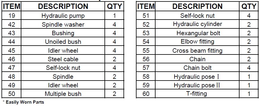
31 31
32 Sub-Structures 32
33 - NOTES - 33
34 Eagle Equipment Lift Warranty Eagle Equipment warrants to the original retail purchaser of an Eagle Automotive Lift that it will replace without charge any part found under normal use, in the United states or Canada, to be defective in materials or workmanship, for a period of one (1) year from date of purchase. Warranty covers parts only; purchaser is responsible for any and all labor requirements. Exclusions This warranty will not apply to any machine: 1. Which has not been operated or maintained according to specifications 2. Which has been abused, misused, altered, or improperly maintained 3. Which has been improperly installed or assembled Other limitations This warranty does not cover: 1. Parts needed for normal maintenance. 2. Wear parts, which include but are not limited to, cables, hoses, slider blocks, chains and rubber pads. 3. On-site labor. Eagle Equipment reserves the right to make improvements and/or design changes to its equipment without any obligation to previously sold, assembled or fabricated equipment. There is no other express warranty on the Eagle Automotive Lift equipment and this warranty is exclusive of and in lieu of all other warranties, expressed or implied, including all warranties of merchantability and fitness for a particular purpose. To the fullest extent allowed by law, Eagle Equipment shall not be liable for loss of use, inconvenience, lost time, commercial loss or other incidental or consequential damages Some States do not allow exclusion or limitation of consequential damages or how long an implied warranty lasts, so that the above limitations and exclusions may not apply. This warranty gives you specific legal rights and you may have other rights, which may vary from State to State. 34


35 Eagle Equipment, a division of Standard Tools and Equipment Co., is a leading distributor of automotive repair and garage service equipment. Established in 1954, Eagle has provided quality equipment at competitive prices for 60 years, carrying a full line of automotive lifts: two-post lifts, four-post lifts, alignment lifts, scissors lifts, low-rise and mid-rise lifts, as well as models of movable service/storage lifts and our MOBILEMAN. We also stock wheel service equipment including: wheel balancers, tire changers, and brake lathes. We offer a full line of parts, as well as technical support. Visit us at: Established in 1979 to service the auto body and collision repair industry, Tools USA is operated by Standard Tools and Equipment Co., offering a wide variety of products for the auto body professional, collision shops and car hobbyist including auto lifts, frame machines, pulling posts, tire equipment, painting accessories, powder coating equipment, sandblasting equipment, paint booths and more. One of the largest paint booth manufacturers in the United States, Tools USA takes pride in building standard and custom engineered paint booths for all types of applications. Visit us at: Delivering Excellence to the Automotive and Painting Industries. Every Product. Every Customer. Every Day. Standard Tools and Equipment Co. was founded in 1996 to provide tools and equipment to the automotive aftermarket industry. They began manufacturing paint booth systems in Having built over 10,000 paint spray booths for various industries, Standard Tools is among the country's largest suppliers. Tools USA was acquired in 1996 and became a part of the Standard Tools and Equipment family of brands. In 2005, Eagle Equipment, a 50-year-old company joined Standard Tools to provide automotive lifts and tire equipment to the repair industry. 35
GLO-8000 SERIES (GLO-8000 & GLO-8000XLT)
") GLO-8000 SERIES (GLO-8000 & GLO-8000XLT) 8,000 LBS. CAPACITY FOUR-POST STORAGE LIFT INSTALLATION & OPERATION MANUAL SERIAL NUMBER: INSTALLATION DATE: EAGLE EQUIPMENT 1-800-336-2776 REV2011 03.0 BD SHIPPING
GLO-8000 SERIES (GLO-8000 & GLO-8000XLT) 8,000 LBS. CAPACITY FOUR-POST STORAGE LIFT INSTALLATION & OPERATION MANUAL SERIAL NUMBER: INSTALLATION DATE: EAGLE EQUIPMENT 1-800-336-2776 REV2011 03.0 BD SHIPPING
Models PR-12F PR-12C PR-15C SURFACE MOUNTED TWO-POST LIFTS INSTALLATION AND OPERATION MANUAL
 Forward this manual to all operators. Failure to operate this equipment as directed may cause injury. INSTALLATION AND OPERATION MANUAL SURFACE MOUNTED TWO-POST LIFTS Models PR-12F PR-12C PR-15C Keep this
GLO-7000 SERIES (GLO-7000 & GLO-7000XLT)
") GLO-7000 SERIES (GLO-7000 & GLO-7000XLT) 7,000 LBS. CAPACITY FOUR-POST STORAGE LIFT (BLUE) INSTALLATION & OPERATION MANUAL SERIAL NUMBER: INSTALLATION DATE: EAGLE EQUIPMENT 1-800-336-2776 (STANDARD) SHIPPING
GLO-7000 SERIES (GLO-7000 & GLO-7000XLT) 7,000 LBS. CAPACITY FOUR-POST STORAGE LIFT (BLUE) INSTALLATION & OPERATION MANUAL SERIAL NUMBER: INSTALLATION DATE: EAGLE EQUIPMENT 1-800-336-2776 (STANDARD) SHIPPING
MS ,000 LBS. CAPACITY FOUR-POST STORAGE/SERVICE LIFT INSTALLATION & OPERATION MANUAL READ THIS MANUAL BEFORE INSTALLING OR OPERATING YOUR LIFT
 MS-8000 (AND MS-8000XLT) 8,000 LBS. CAPACITY FOUR-POST STORAGE/SERVICE LIFT INSTALLATION & OPERATION MANUAL READ THIS MANUAL BEFORE INSTALLING OR OPERATING YOUR LIFT REV 20150316.TIA02 BD INSPECT YOUR
Models: SURFACE MOUNTED FOUR-POST LIFTS INSTALLATION AND OPERATION MANUAL
 Forward this manual to all operators. Failure to operate this equipment as directed may cause injury. INSTALLATION AND OPERATION MANUAL SURFACE MOUNTED FOUR-POST LIFTS Models: FL-18 BP-18 BP-27/ BP-27A
ASSEMBLY & OPERATION INSTRUCTION MANUAL
 LR-26-PAD 6000 lb Capacity Low-Rise Pad Lift ASSEMBLY & OPERATION INSTRUCTION MANUAL 6,000 LB. LOW-RISE PAD LIFT Easy frame lifting on padded runways. Great for wheel and brake work, tire and wheel changing
Read this entire manual before operation begins.
 Read this entire manual before operation begins. Record below the following information which is located on the serial number data plate. Serial No. Model No. Date of Installation Contents Specifications.............
ATTENTION. 1. Do not attempt to use the power unit to extend your cylinder. This must be done manually.
 NSS8XLT Installation Manual ATTENTION By following the instructions in this manual you can save yourself much time, frustration and money. The installation of your lift will take 4-5 hours. Do not rush.
MR6K-48X. Mid-Rise Scissor Lift ASSEMBLY & OPERATION INSTRUCTION MANUAL. 6,000 lbs.
 MR6K-48X Mid-Rise Scissor Lift 6,000 lbs. ASSEMBLY & OPERATION INSTRUCTION MANUAL November 2014 Important! Be sure to read the operating instructions before operating your lift! Getting Ready Make sure
Read this entire manual before operation begins.
 Read this entire manual before operation begins. Record below the following information which is located on the serial number data plate. Serial No. Model No. Date of Installation Contents Specifications.............
Atlas PV-9WP Addendum
 Atlas PV-9WP Addendum 9,000 lb. Capacity Two-Post Overhead Lift The Atlas PV-9WP above ground hoist is 6 inches wider than the Atlas PV-9P, giving it an overall width of 141 (11 9 ) and a drive thru width
Read this entire manual before operation begins.
 Read this entire manual before operation begins. Record below the following information which is located on the serial number data plate. Serial No. Model No. Date of Installation Contents Specifications.............
Model PL-7 / PL-7X AUTOMOBILE STACKER INSTALLATION AND OPERATION MANUAL
 Forward this manual to all operators. Failure to operate this equipment as directed may cause injury. AUTOMOBILE STACKER INSTALLATION AND OPERATION MANUAL Model PL-7 / PL-7X Keep this operation manual
Read this entire manual before operation begins.
 Read this entire manual before operation begins. Record below the following information which is located on the serial number data plate. Serial No. Model No. Date of Installation Contents Specifications.............
Lifting height 5.5" - 72" with adapters " Height overall 165" Width between columns 122" Drive through 109" Width overall 151.
 Model Number TP12KC-D Capacity 12,000 lbs. Lifting height 5.5" - 72" with adapters 79.625" Height overall 165" Width between columns 122" Drive through 109" Width overall 151.125" Arm extension 37.5" -
FP-12L 12,000 LBS. CAPACITY FOUR-POST LIFT INSTALLATION & OPERATION MANUAL READ THIS MANUAL BEFORE INSTALLING OR OPERATING YOUR LIFT
 FP-12L 12,000 LBS. CAPACITY FOUR-POST LIFT INSTALLATION & OPERATION MANUAL READ THIS MANUAL BEFORE INSTALLING OR OPERATING YOUR LIFT REV 20160208.SUN01 BD INSPECT YOUR LIFT UPON DELIVERY. NOTE ANY DAMAGE
Read this entire manual before operation begins.
 Rev. 12/12/2017 Read this entire manual before operation begins. Record below the following information which is located on the serial number data plate. Serial No. Model No. Date of Installation Contents
CONTENTS. Product Features and Specifications Installation Requirement Installation Exploded View Operation Instruction...
 1 CONTENTS Product Features and Specifications... 3 Installation Requirement... 5 Installation... 6 Exploded View... 20 Test... 22 Operation Instruction... 25 Maintenance... 26 Trouble Shooting... 27 Parts
MSC-6KLP Low Profile Mobile Single Column Lift. 6,000 lb. Capacity (1,500 lbs. Max Capacity per Arm) Installation & Operation Manual
 Installation & Operation Manual") Low Profile Mobile Single Column Lift 6,000 lb. Capacity (1,500 lbs. Max Capacity per Arm) Installation & Operation Manual INDEX PREFACE-------------------------------------------------------------------------------
Low Profile Mobile Single Column Lift 6,000 lb. Capacity (1,500 lbs. Max Capacity per Arm) Installation & Operation Manual INDEX PREFACE-------------------------------------------------------------------------------
CONTENTS. Product Features and Specifications...1. Installation Requirement Steps of Installation.. 5. Exploded View Test Run...
 CONTENTS Product Features and Specifications...1 Installation Requirement... 3 Steps of Installation.. 5 Exploded View...18 Test Run...21 Operation Instruction...22 Maintenance... 23 Trouble Shooting...
Read this entire manual before operation begins.
 Read this entire manual before operation begins. Record below the following information which is located on the serial number data plate. Serial No. Model No. Date of Installation Contents Specifications.............
CONTENTS. Product Features and Specifications Installation Requirement Steps of Installation 4. Exploded View Test Run...
 CONTENTS Product Features and Specifications... 1 Installation Requirement... 3 Steps of Installation 4 Exploded View... 14 Test Run... 16 Operation Instruction... 19 Maintenance... 20 Trouble Shooting...
9,000 POUND TWO-COLUMN AUTOMOTIVE LIFT Model: NW-2-9KFP MANUAL
 9,000 POUND TWO-COLUMN AUTOMOTIVE LIFT Model: NW-2-9KFP MANUAL 1 9,000 POUND CAPACITY MODEL: NW-2-9KFP TWO-COLUMN AUTOMOTIVE LIFT READ THIS ENTIRE MANUAL BEFORE OPERATION BEGINS RECORD BELOW THE FOLLOWING
1300 lb Capacity Trike Lift
 M-1300C-TRIKE 1300 lb Capacity Trike Lift USER S MANUAL TRIKE MOTORCYCLE LIFT An extra wide platform designed especially for three-wheel motorcycles. M-1300-TRIKE Trike Motorcycle Lift SPECIFICATIONS:
MR6K lb Capacity Portable Mid-Rise Scissor Lift. Operation Manual
 MR6K-38 6000 lb Capacity Portable Mid-Rise Scissor Lift Operation Manual 6,000 LB. PORTABLE MID-RISE FRAME LIFT A comfortable 38 working height, twin cylinders and double safety locks make this portable
ATD2P11BS. Two-Post Clear Floor Bi-Symmetric Automotive Lift. Installation & Operation Manual. 11,000 lbs. Capacity. (2,750 lbs.
 Two-Post Clear Floor Bi-Symmetric Automotive Lift 11,000 lbs. Capacity (2,750 lbs. Max per Arm) Installation & Operation Manual 1. Safety Information 1.1 Note, Caution and Warning 1.2 Important Information
INSTALLATION & OPERATION MANUAL
 Two-Post Clear Floor Lift (Asymmetric) 9,000 lbs. Capacity (2,250 lbs. Max per Arm) INSTALLATION & OPERATION MANUAL IMPORTANT NOTES READ THE INSTALLATION AND OPERATION MANUAL IN ITS ENTIRETY BEFORE ATTEMPTING
Installation and Service Manual
 RESIDENTIAL PLATFORM LIFTS RPL400 / RPL600 Installation and Service Manual WARNING! STRICT ADHERENCE TO THESE INSTALLATION INSTRUCTIONS IS REQUIRED to promote the safety of those installing this product,
4400-Lb. Capacity Pallet Jack
 Read carefully and understand all ASSEMBLY AND OPERATION INSTRUCTIONS before operating. Failure to follow the safety rules and other basic safety precautions may result in serious personal injury. Item#
TWO POST LIFT INSTALLATION AND OWNERS MANUAL
 TWO POST LIFT INSTALLATION AND OWNERS MANUAL DP15, DP15-2 Capacity 15,000 lbs. 1. TABLE OF CONTENTS 2. Important Information.. 2 3. Section 1 Owner s Manual Safety Instructions... 3 Monthly Maintenance...
MOTORCYCLE LIFTS SPECIFICATIONS: M-1000C M-1500C-HR
 M1000C 1000l bcapaci t y Mot or cycl eli f t MOTORCYCLE LIFTS These lift tables are ideal for making repairs to motorcycles, snowmobiles, ATVs, jet skis, etc. Choose from a range of accessories to customize
9,000 POUND TWO-COLUMN AUTOMOTIVE LIFT. Model: NW-2-9KACD MANUAL
 9,000 POUND TWO-COLUMN AUTOMOTIVE LIFT Model: NW-2-9KACD MANUAL 1 9,000 POUND CAPACITY MODEL: NW-2-9KACD TWO-COLUMN AUTOMOTIVE LIFT READ THIS ENTIRE MANUAL BEFORE OPERATION BEGINS RECORD BELOW THE FOLLOWING
Installation Instructions Capacity 10,000 lbs. (100 Series Lift)
") Installation Instructions Capacity 10,000 lbs. (100 Series Lift) IMPORTANT Reference ANSI/ALI ALIS, Safety Requirements for Installation and Service of Automotive Lifts before installing lift. OPERATING
Installation Instructions Capacity 10,000 lbs. (100 Series Lift) IMPORTANT Reference ANSI/ALI ALIS, Safety Requirements for Installation and Service of Automotive Lifts before installing lift. OPERATING
Floor Plate Style Lift And Overhead Beam Style Lift. Two Post Lift
 Floor Plate Style Lift And Overhead Beam Style Lift 9,000 POUND Two Post Lift ASSEMBLY & OPERATION INSTRUCTION TABLE OF CONTENTS Important Note Page 3 Definition Page 4 Preparation and General Information
Read this entire manual before operation begins.
 Read this entire manual before operation begins. Record below the following information which is located on the serial number data plate. Serial No. Model No. Date of Installation Contents Specifications.............
MODEL QMR6 PORTABLE MID-RISE LIFT 6,000 lb Capacity 1500 lb Per Arm INSTALLATION, OPERATION AND MAINTENANCE MANUAL
 MODEL QMR6 PORTABLE MID-RISE LIFT 6,000 lb Capacity 1500 lb Per Arm INSTALLATION, OPERATION AND MAINTENANCE MANUAL IMPORTANT!!! READ THIS MANUAL COMPLETELY BEFORE INSTALLING OR OPERATING THE LIFT 200 CABEL
Read this entire manual before operation begins.
 Revised 9/5/2018 Read this entire manual before operation begins. Record below the following information which is located on the serial number data plate. Serial No. Model No. Date of Installation Contents
CONTENTS. Product Features and Specifications...1. Installation Requirement...3. Steps of Installation...4. Exploded View Test Run...
 TP10AS 2-POST LIFT CONTENTS Product Features and Specifications...1 Installation Requirement...3 Steps of Installation...4 Exploded View...24 Test Run....28 Operation Instruction...29 Maintenance...30
It is the shop owner's responsibility to train all operators in lift operation and safety.
 2 Your new lift will provide years of dependable service if installed, operated and maintained properly. Read and be prepared to follow all safety, installation, operation, and maintenance instructions
1000-lb Hydraulic Truck Crane
 1000-lb Hydraulic Truck Crane Owner s Manual WARNING: Read carefully and understand all ASSEMBLY AND OPERATION INSTRUCTIONS before operating. Failure to follow the safety rules and other basic safety precautions
1000-LB. MOTORCYCLE LIFT TABLE OWNER S MANUAL
 1000-LB. MOTORCYCLE LIFT TABLE OWNER S MANUAL WARNING: Read carefully and understand all ASSEMBLY AND OPERATION INSTRUCTIONS before operating. Failure to follow the safety rules and other basic safety
INSTALLATION, OPERATION & MAINTENANCE MANUAL
 INSTALLATION, OPERATION & MAINTENANCE MANUAL Two Post Surface Mounted Lift MODEL X10 10,000 LBS. CAPACITY 2500 LBS. PER ARM 200 Cabel Street, P.O. Box 3944 Louisville, Kentucky 40201-3944 Email:sales@challengerlifts.com
Installation Instructions X-Force UTV Lift (000 Series) Capacity 2,275 lbs (1,035 kg)
 Capacity 2,275 lbs (1,035 kg)") Installation Instructions X-Force UTV Lift (000 Series) Capacity 2,275 lbs (1,035 kg) Read entire manual before assembling, installing, operating, or servicing this equipment. LP20640 IN20793 September
Installation Instructions X-Force UTV Lift (000 Series) Capacity 2,275 lbs (1,035 kg) Read entire manual before assembling, installing, operating, or servicing this equipment. LP20640 IN20793 September
Electric Chainsaw Sharpener With Bar Mount
 Electric Chainsaw Sharpener With Bar Mount Owner s Manual WARNING: Read carefully and understand all ASSEMBLY AND OPERATION INSTRUCTIONS before operating. Failure to follow the safety rules and other basic
KENCOVE PD100 MANUAL TILT POST DRIVER
 OPERATOR S MANUAL KENCOVE PD100 MANUAL TILT POST DRIVER WWW.KENCOVE.COM 800-536-2683 344 KENDALL RD, BLAIRSVILLE, PA 15717 Table of Contents Specifications/Requirements 1 Introduction 2 Equipment Inspection
HYDRAULIC LEVELING SYSTEMS OPERATIONS MANUAL (For systems with touch pad part number , , , , or no number at all)
") HYDRAULIC LEVELING SYSTEMS OPERATIONS MANUAL (For systems with touch pad part number 500089, 500105, 500210, 500456, 500535 or no number at all) Visit us on the web at www.powergearus.com 82-L0040-01 Rev.
HYDRAULIC LEVELING SYSTEMS OPERATIONS MANUAL (For systems with touch pad part number 500089, 500105, 500210, 500456, 500535 or no number at all) Visit us on the web at www.powergearus.com 82-L0040-01 Rev.
INSTALLATION MANUAL & OPERATION INSTRUCTIONS. OVERHEAD CAR LIFT 2-POST LIFT AUTO HOIST APlusLift HW-10KOH
 INSTALLATION MANUAL & OPERATION INSTRUCTIONS OVERHEAD CAR LIFT 2-POST LIFT AUTO HOIST APlusLift HW-10KOH 1 READ THIS MANUAL COMPLETELY BEFORE INSTALLING LIFT!!! DISTRIBUTED BY: Songa Enterprises LLC 8512
2-Post Lift Operations and Maintenance Manual
 2-Post Lift Operations and Maintenance Manual Table Of Contents Safety Instructions... 2 Owner/Employer Responsibilities / Operating Conditions... 3 Operating Instructions... 4 Maintenance Instructions...
Two Post Surface Mounted Lift 12,000 LBS. CAPACITY 3000 LBS. PER ARM
 INSTALLATION, OPERATION & MAINTENANCE MANUAL Two Post Surface Mounted Lift MODEL EELR537A 12,000 LBS. CAPACITY 3000 LBS. PER ARM Snap-On Equipment 309 Exchange Avenue, Conway, Arkansas, 72032 Tel: 501-450-1500
INSTALLATION AND OPERATION MANUAL
 PLEASE READ THE ENTIRE CONTENTS OF THIS MANUAL PRIOR TO INSTALLATION AND OPERATION. BY PROCEEDING YOU AGREE THAT YOU FULLY UNDERSTAND AND COMPREHEND THE FULL CONTENTS OF THIS MANUAL. FORWARD THIS MANUAL
INSTALLATION AND OPERATION MANUAL
 PLEASE READ THE ENTIRE CONTENTS OF THIS MANUAL PRIOR TO INSTALLATION AND OPERATION. BY PROCEEDING YOU AGREE THAT YOU FULLY UNDERSTAND AND COMPREHEND THE FULL CONTENTS OF THIS MANUAL. FORWARD THIS MANUAL
Hydraulic Bead Breaker Kit
 Hydraulic Bead Breaker Kit Owner s Manual WARNING: Read carefully and understand all ASSEMBLY AND OPERATION INSTRUCTIONS before operating. Failure to follow the safety rules and other basic safety precautions
Wheel Horse. 44 Snowthrower. for 5xi Lawn and Garden Tractors. Model No & Up. Operator s Manual
 FORM NO. 8 Rev A Wheel Horse Snowthrower for 5xi Lawn and Garden Tractors Model No. 7966 890050 & Up Operator s Manual IMPORTANT: Read this manual, and your tractor manual, carefully. They contain information
TP15KC-KX Two-Post Clear Floor Lift
 TP15KC-KX Two-Post Clear Floor Lift (Symmetric) 15,000 lbs. Capacity (3,750 lbs. Max per Arm) ASSEMBLY & OPERATION INSTRUCTION MANUAL Feb. 2017 IMPORTANT NOTES READ THE INSTALLATION AND OPERATION MANUAL
Challenger Lifts, Inc. MODEL 12000
 Challenger Lifts, Inc. MODEL 12000 TWO POST SURFACE MOUNTED LIFT OPERATION, INSTALLATION & MAINTENANCE MANUAL IMPORTANT READ THIS MANUAL COMPLETELY BEFORE INSTALLING OR OPERATING THE LIFT 200 CABEL STREET,
Read this entire manual before operation begins.
 Read this entire manual before operation begins. Record below the following information which is located on the serial number data plate. Serial No. Model No. Date of Installation Contents Specifications.............
4400-Lb. Capacity Extra-Long Pallet Jack
 4400-Lb. Capacity Extra-Long Pallet Jack Owner s Manual WARNING: Read carefully and understand all ASSEMBLY AND OPERATION INSTRUCTIONS before operating. Failure to follow the safety rules and other basic
Heavy Duty Jack Stands
 Heavy Duty Jack Stands Operating Instructions & Parts Manual Made in the U.S.A. Model Number HW93511 Capacity per pair 10 Ton Model Number HW93512 Capacity per pair 10 Ton This is the safety alert symbol.
Model SL-12K-A SCISSOR LIFT. wheel alignment model. (11000 LBS / 5000Kg Capacity) INSTALLATION & OPERATION INSTRUCTION (SECOND EDITION)
 INSTALLATION & OPERATION INSTRUCTION (SECOND EDITION)") Model SL-12K-A SCISSOR LIFT wheel alignment model (11000 LBS / 5000Kg Capacity) INSTALLATION & OPERATION INSTRUCTION (SECOND EDITION) 2007. 6. CONTENTS Chapter 1 Introduction & Specifications ---------------------------------------
Model SL-12K-A SCISSOR LIFT wheel alignment model (11000 LBS / 5000Kg Capacity) INSTALLATION & OPERATION INSTRUCTION (SECOND EDITION) 2007. 6. CONTENTS Chapter 1 Introduction & Specifications ---------------------------------------
Challenger Lifts, Inc. MODELS & 18000
 Challenger Lifts, Inc. MODELS 15000 & 18000 TWO POST SURFACE MOUNTED LIFT OPERATION, INSTALLATION & MAINTENANCE MANUAL IMPORTANT READ THIS MANUAL COMPLETELY BEFORE INSTALLING OR OPERATING THE LIFT 200
Hydraulic Transmission Jack, Telescopic
 Operating Instructions & Parts Manual Hydraulic Transmission Jack, Telescopic Model 4000 400 (Air Operated) Capacity 000 lbs. 000 lbs. Model 4000 Model 400 U.S. Patent No. 6,02,377! This is the safety
SPECIFICATIONS GENERAL SAFETY RULES PERSONAL SAFETY. Save This Manual TOOL USE AND CARE WORK AREA
 SPECIFICATIONS 2 Forged Safety Latch Hooks Cable extends to: 44 Drop forged steel hanging bracket Heavy duty 3/16 Steel Cable Pulling Capacity: 1200 LB. One piece double ratchet gear Save This Manual You
Hydraulic Wheel Dolly
 Hydraulic Wheel Dolly Operating Instructions & Parts Manual Model Number HW93766 Capacity 3/4 Ton Made in the U.S.A. This is the safety alert symbol. It is used to alert you to potential personal injury
Installation Manual TWM Performance Short Shifter Cobalt SS/SC, SS/TC, HHR SS, Ion Redline and Saab 9-3
 Page 1 Installation Manual TWM Performance Short Shifter Cobalt SS/SC, SS/TC, HHR SS, Ion Redline and Saab 9-3 Please Note: It is preferable to park on a flat surface, as you will have to engage and disengage
Hydraulic Wheel Dolly
 Hydraulic Wheel Dolly Operating Instructions & Parts Manual Model Number HW93765 Capacity 3/4 Ton Made in the U.S.A. This is the safety alert symbol. It is used to alert you to potential personal injury
Large Hydraulic Bead Breaker
 Large Hydraulic Bead Breaker Owner s Manual WARNING: Read carefully and understand all ASSEMBLY AND OPERATION INSTRUCTIONS before operating. Failure to follow the safety rules and other basic safety precautions
Air Curtain. Installation, Operating and Maintenance Instructions
 Installation, Operating and Maintenance Instructions Save this manual for future reference. Air Curtain Model Numbers: ES026, ES036, ES042, ES048, ES060, ES072 READ THIS OWNER S MANUAL CAREFULLY BEFORE
HIGHLANDER Residential Platform Lift
 HIGHLANDER Residential Platform Lift RPL400 RPL600 This manual has been provided to assist you with lift installation and operation. For further assistance please contact your authorized Harmar dealer
Index. 1. Important safety instructions Overview of the lift Installation instructions Operation instructions 8-9
 2 Index 1. Important safety instructions 4-5 1.1 Safety Warnings 1.2 Qualified personnel 1.3 Safety 1.4 Warning signs 2. Overview of the lift 6 2.1 General descriptions 2.2 Technical data 2.3 Construction
Operating Instructions & Parts Manual. Fuel Tank Adapter
 Operating Instructions & Parts Manual Fuel Tank Adapter Model Number 40080 Capacity 80 lb.! This is the safety alert symbol. It is used to alert you to potential personal injury hazards. Obey all safety
MIDRISE MODEL SM60F_1 // SM60F_A 6,500 LB. CAPACITY
 INSTALLATION and OPERATION MANUAL READ THIS INSTRUCTION MANUAL THOROUGHLY BEFORE INSTALLING, OPERATING, SERVICING OR MAINTAINING THE LIFT. SAVE THIS MANUAL. NOV 2007 REV.B MIDRISE MODEL SM60F_1 // SM60F_A
Garden Hose Reel with 3/4In. x 100Ft. Hose. Owner s Manual
 Garden Hose Reel with 3/4In. x 100Ft. Hose Owner s Manual WARNING: Read carefully and understand all ASSEMBLY AND OPERATION INSTRUCTIONS before operating. Failure to follow the safety rules and other basic
Remove the 3-11mm nuts holding mirror on. Don t drop the nuts!
 2005-2012 Ford Mustang Puddle Lamp Kit Parts List: Quantity: Tool List: LED Lamps 2 Flat head screwdriver Seals 2 Ratchet & Socket set OR Nuts 2 Adjustable Wrench Wiring harness 1 Drill & 11/16 th bit
Model FP12K-K Flat Deck Four-Post Lift
 Model FP12K-K Flat Deck Four-Post Lift (12,000LBS Capacity) ASSEMBLY & OPERATION INSTRUCTION 2006.4. TABLE OF CONTENTS Important Note--------------------------------------------------------------------------------Page
CONTENTS: SPECIFICATIONS 5712BT - 12 TON BENCH TOP HYDRAULIC SHOP PRESS OWNER'S MANUAL
 OWNER'S MANUAL CONTENTS: Page 1 Specifications 2 Warning Information 3 Assembly and Operating Instructions 4 Preventative Maintenance and Warranty Information 5 Exploded View Drawing and Parts List SPECIFICATIONS
Perfect Park 7000 Installation & Unloading Instructions Operating Manual
 Perfect Park 7000 Installation & Unloading Instructions Operating Manual 1) Always file a claim with the truck line if the lift has been damaged! (If you don t originally notice the damage, but find some
ASSEMBLY & OPERATION MANUAL. CDVK2 Power Tower RECORD SERIAL NUMBER HERE
 ASSEMBLY & OPERATION MANUAL CDVK2 Power Tower RECORD SERIAL NUMBER HERE www.inspirefitness.net by Health In Motion LLC Feb. 2011 TABLE OF CONTENTS Section Description.. Page Instructions.. 1 Tools Required
Manual Chain Hoist. Owner s Manual
 Manual Chain Hoist Owner s Manual WARNING: Read carefully and understand all ASSEMBLY AND OPERATION INSTRUCTIONS before operating. Failure to follow the safety rules and other basic safety precautions
EZ LINER EXPRESS USERS MANUAL
 EZ LINER EXPRESS 2013 Vehicle Service Group CHIEF'S LIMITED ONE-YEAR WARRANTY & LIABILITY Chief Automotive Technologies warrants for one year from date of installation and/or purchase any components of
SCISSOR LIFT Model MR6K-38 /161108A 6,000lb Capacity Operation Manual
 SCISSOR LIFT Model MR6K-38 /161108A 6,000lb Capacity Operation Manual (Version A) 2009. Apr. CONTENT 1. Safety Note, Caution and Warning Important Information Safety Instructions 2. Technical Manual Product
FP7K&FP7KXLT REV A
 FP7K&FP7KXLT 7000l bcapaci t y Ser vi ce/ St or ageli f t I ns t a l l a t i o n& Ope r a t i o nma nua l REV A-080113 7,000 LB./9,000 LB. STORAGE /SERVICE LIFT 7,000 lb./ 9,000 lb.capacity and large
CONTENTS. Product Features and Specifications...1. Installation Requirement Steps of Installation.. 5. Exploded View Test Run...
 CONTENTS Product Features and Specifications...1 Installation Requirement... 4 Steps of Installation.. 5 Exploded View...21 Test Run...26 Operation Instruction...27 Maintenance... 28 Trouble Shooting...
Heavy-Duty Welding Fabrication Table
 Heavy-Duty Welding Fabrication Table with Fix-Up Kit Owner s Manual WARNING: Read carefully and understand all ASSEMBLY AND OPERATION INSTRUCTIONS before operating. Failure to follow the safety rules and
TWO POST LIFT INSTALLATION AND OWNERS MANUAL. January 2008 rev. E I MAN
 TWO POST LIFT INSTALLATION AND OWNERS MANUAL DP15, DP15-2 Capacity 15,000 lbs. January 2008 rev. E 1. TABLE OF CONTENTS 2. Important Information.. 2 3. Section 1 Owner s Manual Safety Instructions... 3
Amarr SuperFlex. Installation Instructions and Owner's Manual. Entrematic 165 Carriage Court Winston Salem, NC
 Entrematic 165 Carriage Court Winston Salem, NC 27105 www.amarr.com 877-512-6277 Amarr SuperFlex Installation Instructions and Owner's Manual Do not install, operate or service this product unless you
3-Pt. Quick Hitch. Owner s Manual
 3-Pt. Quick Hitch Owner s Manual WARNING: Read carefully and understand all ASSEMBLY AND OPERATION INSTRUCTIONS before operating. Failure to follow the safety rules and other basic safety precautions may
Heavy Duty Four Wheeled Walker
 Heavy Duty Four Wheeled Walker Weight Capacity: 500 lbs. ITEM # W1802 Made in China 2011 ESSENTIAL MEDICAL SUPPLY, INC. Manufactured for Orlando, FL 32822 -- SAVE THESE INSTRUCTIONS -- Do not attempt to
5,500 lbs. Pallet Jack
 5,500 lbs. Pallet Jack ATD-7406 Operating Instructions & Parts Manual Capacity 5,500 lbs.! The safety alert symbol is used to alert you to potential personal injury hazards. Obey all safety messages that
VEGETABLE OIL DISPOSAL UNIT (MSDU) OPERATOR & SERVICE MANUAL
 OPERATOR & SERVICE MANUAL") VEGETABLE OIL DISPOSAL UNIT (MSDU) OPERATOR & SERVICE MANUAL MANUFACTURED BY P.O. BOX 51000 SHREVEPORT, LOUISIANA 71135-1000 PHONE 1-318-865-1711 1-800-24 FRYER This equipment chapter is to be inserted
VEGETABLE OIL DISPOSAL UNIT (MSDU) OPERATOR & SERVICE MANUAL MANUFACTURED BY P.O. BOX 51000 SHREVEPORT, LOUISIANA 71135-1000 PHONE 1-318-865-1711 1-800-24 FRYER This equipment chapter is to be inserted
Adjustable Steel Welding Table
 Adjustable Steel Welding Table Owner s Manual WARNING: Read carefully and understand all ASSEMBLY AND OPERATION INSTRUCTIONS before operating. Failure to follow the safety rules and other basic safety
Model E600 Tarping System
 10 Boulder Parkway N. Oxford, MA 01537 866-353-5826 pioneersales@wastequip.com www.pioneercoverall.com Model E600 Tarping System Installation Instructions WARNING: In order to prevent damage, the tarp
ATD-4P9DXL. Four Post Lift. 9,000 lbs. Capacity. (4,500 lbs. per axle) INSTALLATION / OWNERS MANUAL
 INSTALLATION / OWNERS MANUAL") ATD-4P9DXL Four Post Lift 9,000 lbs. Capacity (4,500 lbs. per axle) INSTALLATION / OWNERS MANUAL Jan 2017 READ THIS MANUAL THOROUGHLY BEFORE INSTALLING, OPERATING, OR MAINTAINING THIS LIFT. WHEN DONE WITH
ATD-4P9DXL Four Post Lift 9,000 lbs. Capacity (4,500 lbs. per axle) INSTALLATION / OWNERS MANUAL Jan 2017 READ THIS MANUAL THOROUGHLY BEFORE INSTALLING, OPERATING, OR MAINTAINING THIS LIFT. WHEN DONE WITH
Installation Instructions Capacity 10,000 lbs. DP10 (200 Series Lift)
") Installation Instructions Capacity 10,000 lbs. DP10 (200 Series Lift) IMPORTANT Reference ANSI/ALI ALIS, Safety Requirements for Installation and Service of Automotive Lifts before installing lift. OPERATING
Installation Instructions Capacity 10,000 lbs. DP10 (200 Series Lift) IMPORTANT Reference ANSI/ALI ALIS, Safety Requirements for Installation and Service of Automotive Lifts before installing lift. OPERATING
INSTALLATION and OPERATION MANUAL
 INSTALLATION and OPERATION MANUAL AC2012S 12,000 12,000 LB. LB. (SYMMETRICAL) READ and SAVE THIS INSTRUCTION MANUAL P.O. Box 15540 Richmond, VA 23227 804-798-8922 www.accu-turn.com 1-800-551-2228 APR 2004
ATD-2P9A 9,000 lbs. Two Post Clear Floor Lift Owner s Manual
 ATD-2P9A 9,000 lbs. Two Post Clear Floor Lift Owner s Manual Features: Specifications: IMPORTANT NOTES READ THE INSTALLATION AND OPERATION MANUAL IN ITS ENTIRETY BEFORE ATTEMPTING TO INSTALL THE LIFT.
RollSeal 1733 County Road 68 Bremen, Alabama Part No Rev Owner s Manual RS-Divider Curtain
 1. 2. 7 3. 4. RollSeal 1733 County Road 68 Bremen, Alabama 35033 256-287-7000 Part No 4801-5176 Rev 12-11-17 Owner s Manual RS-Divider Curtain Table of Contents 1 Warnings (Avertissements)... 3 2 Limited
Installation Manual. Installation Instructions. Operation. TP15KC Parts Check List Notes about your TP15KC lift
 Installation Manual Parts Check List Notes about your lift Installation Instructions Step 1 Measure lift area and check for defects Step 2 Cylinder assembly Step 3 Position columns and uprights, level
INSTALLATION AND OPERATION MANUAL 1,500 POUND CAPACITY MOTORCYCLE / ATV LIFT Model: RML-1500XL
 PLEASE READ THE ENTIRE CONTENTS OF THIS MANUAL PRIOR TO INSTALLATION AND OPERATION. BY PROCEEDING YOU AGREE THAT YOU FULLY UNDERSTAND AND COMPREHEND THE FULL CONTENTS OF THIS MANUAL. FORWARD THIS MANUAL
CRD610 Automatic Fitting Inserter
 CRD610 Automatic Fitting Inserter OPERATIONS MANUAL VERSION 1.2 LAST EDITED 12.12.2018 cleanroomdevices.com 1 Table of Contents Title Page. 1 Table of Contents...2 1.0 General Product & Safety Information....3
Mini Lever Hoist. Owner s Manual
 Mini Lever Hoist Owner s Manual WARNING: Read carefully and understand all ASSEMBLY AND OPERATION INSTRUCTIONS before operating. Failure to follow the safety rules and other basic safety precautions may